WO2025047751A1 - ローター - Google Patents
ローター Download PDFInfo
- Publication number
- WO2025047751A1 WO2025047751A1 PCT/JP2024/030532 JP2024030532W WO2025047751A1 WO 2025047751 A1 WO2025047751 A1 WO 2025047751A1 JP 2024030532 W JP2024030532 W JP 2024030532W WO 2025047751 A1 WO2025047751 A1 WO 2025047751A1
- Authority
- WO
- WIPO (PCT)
- Prior art keywords
- magnet
- rotor
- elastic body
- rotor core
- gap
- Prior art date
- Legal status (The legal status is an assumption and is not a legal conclusion. Google has not performed a legal analysis and makes no representation as to the accuracy of the status listed.)
- Pending
Links
Images



Classifications
-
- H—ELECTRICITY
- H02—GENERATION; CONVERSION OR DISTRIBUTION OF ELECTRIC POWER
- H02K—DYNAMO-ELECTRIC MACHINES
- H02K1/00—Details of the magnetic circuit
- H02K1/06—Details of the magnetic circuit characterised by the shape, form or construction
- H02K1/22—Rotating parts of the magnetic circuit
- H02K1/27—Rotor cores with permanent magnets
- H02K1/2706—Inner rotors
- H02K1/272—Inner rotors the magnetisation axis of the magnets being perpendicular to the rotor axis
- H02K1/274—Inner rotors the magnetisation axis of the magnets being perpendicular to the rotor axis the rotor consisting of two or more circumferentially positioned magnets
- H02K1/2753—Inner rotors the magnetisation axis of the magnets being perpendicular to the rotor axis the rotor consisting of two or more circumferentially positioned magnets the rotor consisting of magnets or groups of magnets arranged with alternating polarity
- H02K1/276—Magnets embedded in the magnetic core, e.g. interior permanent magnets [IPM]
Definitions
- the present invention relates to an IPM (Interior Permanent Magnet) rotor in which magnets are housed in magnet housing holes in a rotor core.
- IPM Interior Permanent Magnet
- Conventional rotors include those in which magnets are fixed in magnet housing holes in the rotor using resin, as in Patent Document 1.
- resin creates magnetic resistance in the magnetic circuit, which reduces the amount of magnetic flux.
- Patent Document 2 there is a rotor in which a spring plate portion that protrudes into the magnet accommodating hole is integrally formed with one of the core pieces that make up the rotor.
- the spring plate portion is bent by the magnet inserted into the magnet accommodating hole.
- the bent spring plate portion presses the magnet against the inner circumference of the magnet accommodating hole, fixing it in place.
- the core pieces are made of magnetic steel plates and other materials that are not suitable for springs. For this reason, the spring plate portion that is integrated with the core pieces is prone to sagging, which reduces the load that secures the magnets. As a result, with conventional technology, the magnets could not be secured in place sufficiently, causing vibrations in the magnets and risk of rotor malfunction.
- the problem to be solved was the inability to adequately fix the magnets while suppressing magnetic resistance.
- the present invention provides a rotor comprising a rotor core with a magnet accommodating hole, a magnet arranged in the magnet accommodating hole, and an elastic body arranged in the gap between the rotor core and the magnet in the magnet accommodating hole in the magnetization direction to hold the magnet in the magnet accommodating hole, the elastic body being made of a magnetic body separate from the rotor core and the magnet.
- the present invention is able to adequately fix the magnet while suppressing magnetic resistance.
- FIG. 1 is a perspective view of a rotor according to a first embodiment of the present invention.
- FIG. 2 is a plan view of the rotor of FIG.
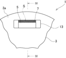
- FIG. 3 is an enlarged plan view showing a portion of the rotor of FIG.
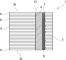
- FIG. 4 is a cross-sectional view taken along line VI-VI in FIG. 5A and 5B are enlarged plan views each showing a part of a rotor according to a modified example.
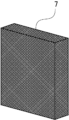
- FIG. 6 is a perspective view showing an elastic body of the rotor of FIG.
- the goal of sufficiently fixing the magnet while suppressing magnetic resistance was achieved by placing an elastic body made of a separate magnetic material in the gap between the rotor core and the magnet inside the magnet housing hole.
- the rotor 1 comprises a rotor core 3, a magnet 5, and an elastic body 7.
- the rotor core 3 comprises a magnet accommodating hole 13, and the magnet 5 is disposed within the magnet accommodating hole 13.
- the elastic body 7 is disposed in the gap S in the magnetization direction between the rotor core 3 and the magnet 5 within the magnet accommodating hole 13, and holds the magnet 5 within the magnet accommodating hole 13.
- This elastic body 7 is made of a magnetic body separate from the rotor core 3 and the magnet 5.
- the elastic body 7 may be of various types, for example an assembly of one or more wires.
- the elastic body 7 may be a mesh spring or an assembly of metal fibers.
- the surface of the wires may also be insulated.
- the elastic body 7 may have a value obtained by multiplying the relative permeability and the space factor (%) of 1000 or more.
- the space factor is the percentage of the gap S between the rotor core 3 and the magnet 5 in which the elastic body 7 is placed that is occupied by the elastic body 7.
- the elastic body 7 can be located on either side of the magnetization direction of the magnet 5, or on both sides. If the magnetization direction is the radial direction of the rotor core 3, it is preferable that the elastic body 7 is located at least radially outward of the magnet 5.
- Fig. 1 is a perspective view of a rotor according to a first embodiment of the present invention.
- Fig. 2 is a plan view of the rotor of Fig. 1.
- Fig. 3 is an enlarged view showing a part of the rotor of Fig. 2.
- Fig. 4 is a cross-sectional view taken along line VI-VI of Fig. 3.
- the rotor 1 in Figures 1 to 4 constitutes a rotating electric machine together with the stator.
- the rotor 1 comprises a rotor core 3, magnets 5, and an elastic body 7.
- This rotor 1 is an IPM (Interior Permanent Magnet) rotor in which the magnets 5 are housed in the magnet housing holes 13 of the rotor core 3.
- the rotor core 3 is made by stacking multiple core pieces 9 made of annular plate material in the axial direction.
- the multiple core pieces 9 of the rotor core 3 are integrated together by welding, crimping, adhesive bonding, etc.
- Each core piece 9 is formed by punching out an electromagnetic steel sheet or a silicon steel sheet, for example.
- the axial direction means the direction along the axis of the rotor 1.
- the rotor core 3 has an overall cylindrical shape.
- An axial hole 11 is provided in the center of the rotor core 3, and magnet accommodating holes 13 are provided around the axial hole 11.
- the axial hole 11 and magnet accommodating holes 13 pass through the rotor core 3 in the axial direction and open at both end faces 3a of the rotor core 3 in the axial direction. Note that the magnet accommodating holes 13 may open only at one end face 3a of the rotor core 3.
- the magnet accommodating holes 13 are arranged at four equal intervals in the circumferential direction of the rotor core 3.
- the circumferential direction refers to the direction along the outer periphery of the rotor core 3.
- Each magnet accommodating hole 13 is rectangular in plan view, and the dimension perpendicular to the radial direction is greater than the radial dimension.
- the radial direction refers to the direction along the diameter of the rotor core 3. Note that various changes can be made to the shape, number, arrangement, etc. of the magnet accommodating holes 13.
- a magnet 5 is accommodated in each magnet accommodating hole 13.
- the magnet 5 can be composed of a permanent magnet (including pre-magnetized magnets), such as ferrite-based sintered magnet pieces or neodymium magnet pieces.
- the magnet 5 is a plate-shaped body that fits the magnet accommodating hole 13, and the dimensions of each part of the magnet 5 are set smaller than the dimensions of each part of the magnet accommodating hole 13. This creates a gap S between the rotor core 3 and the magnet 5 inside the magnet accommodating hole 13.
- An elastic body 7 is disposed in the radial gap S. Since the gap S is a space in which the elastic body 7 is disposed, it is shown in the figure by a virtual line drawn from the elastic body 7. The gap S does not need to be defined by the magnet 5 and the rotor core 3, and other members may be interposed between the elastic body 7 and the magnet 5 or the rotor core 3.
- the elastic body 7 is located radially outward from the magnet 5.
- the elastic body 7 can also be located radially inward from the magnet 5 as shown in Figure 5 ( Figure 5(A)), or on both sides of the magnet 5 ( Figure 5(B)).
- the radial direction is the magnetization direction, which is the direction in which the magnetic flux of the magnet 5 flows. Therefore, the elastic body 7 is disposed in the gap S in the magnetization direction between the rotor core 3 and the magnet 5 in the magnet accommodating hole 13.
- the magnetization direction is the direction of the magnetic flux at least from the magnet 5 to the rotor core 3, and can be made different from the radial direction depending on the specifications of the rotor 1, etc.
- the magnetization direction can be the circumferential direction. In this case, the gap S between the rotor core 3 and the magnet 5 in the magnet accommodating hole 13 becomes a circumferential gap, and the elastic body 7 is disposed in this gap S.
- FIG. 6 is a perspective view showing the elastic body 7.
- the elastic body 7 holds the magnet 5 in the magnet accommodating hole 13.
- This elastic body 7 is made of a magnetic material separate from the rotor core 3 and the magnet 5.
- the elastic body 7 is generally plate-shaped, and is formed with a dimension in the magnetization direction larger than the gap S. This elastic body 7 is placed in the gap S in a radially compressed state, and presses and fixes the magnet 5 against the rotor core 3. Note that the elastic body 7 does not need to be plate-shaped as long as it can be placed in the gap S in a radially compressed state.
- the material of the elastic body 7 is not particularly limited, and various materials can be used as long as it is magnetic.
- the elastic body 7 in this embodiment is an assembly of one or more wires, for example, an assembly of metal fibers such as steel wool, or a mesh spring.
- Mesh springs are made by weaving spring wire and pressing it into shape.
- Metal fiber aggregates are made of nonwoven fabric, woven fabric, sintered bodies, etc. of metal fibers formed into sheets.
- the wires used in mesh springs and the metal fibers that make up the aggregates may have their surfaces insulated with resin, etc.
- the elastic body 7 preferably has a value of 1000 or more obtained by multiplying its relative permeability and space factor.
- the relative permeability is 25 or more and the space factor is 40% or more.
- the space factor is the percentage of the gap S in which the elastic body 7 is placed that is occupied by the elastic body 7. If the value of the relative permeability multiplied by the space factor is 1000 or more, the following magnetic resistance can be achieved when the magnet 5 is fixed with resin.
- a jig is used to compress the elastic body 7 in the radial direction and insert it into the gap S. Then, the jig is removed, leaving the elastic body 7 in the gap S, while simultaneously inserting the magnet.
- the elastic body 7 may be compressed in the radial direction using a jig while overlapping the magnet 5, and the elastic body 7 may be inserted into the gap S together with the magnet 5.
- the elastic body 7 may be prepared in a state in which it is longer than the gap S, and the elastic body 7 may be inserted into the magnet accommodating hole 13 first.
- the magnet 5 is inserted into the magnet accommodating hole 13 while compressing the elastic body 7 in the radial direction.
- the magnet 5 can be inserted smoothly by pulling the elastic body 7 in the insertion direction of the magnet 5.
- the portion of the elastic body 7 that protrudes from the magnet accommodating hole 13 may be cut off after the magnet 5 is fixed.
- an elastic body 7 is disposed in the gap S in the magnetization direction between the rotor core 3 and the magnet 5 in the magnet accommodating hole 13. This elastic body 7 makes it possible to press and hold the magnet 5 against the rotor core 3 in the magnetization direction in the magnet accommodating hole 13.
- the elastic body 7 is separate from the rotor core 3 and magnets 5, it can be made of a material that does not easily sag, allowing the magnets 5 to be securely held.
- the elastic body 7 is made of a magnetic material, it is possible to reduce the magnetic resistance in the gap S.
- the value obtained by multiplying the relative permeability and the space factor of the elastic body 7 is 1000 or more, so the magnetic resistance can be reliably reduced.
- the rotor 1 of this embodiment can adequately fix the magnets 5 while suppressing magnetic resistance. Therefore, the rotor 1 can achieve improved performance, such as increased output torque.
- the elastic body 7 can fill the gap S, which changes in size accordingly, and securely hold the magnet 5 while reducing magnetic resistance. In other words, the elastic body 7 can increase the tolerance of the magnet 5 and the magnet accommodating hole 13.
- the elastic body 7 can absorb such unevenness in the magnet accommodating hole 13 and securely hold the magnet 5. Moreover, by engaging the unevenness with the elastic body 7, the elastic body 7 can securely hold the magnet accommodating hole 13, resulting in an improved holding condition of the magnet 5.
- the magnet 5 can be received by the entire inner surface of the opposing magnet accommodating hole 13 via the elastic body 7.
Landscapes
- Engineering & Computer Science (AREA)
- Power Engineering (AREA)
- Permanent Field Magnets Of Synchronous Machinery (AREA)
Abstract
磁気抵抗を抑制しながら磁石の固定を十分に行うことが可能なローターを提供する。磁石収容穴13を備えたローターコア3と、磁石収容穴13に配置された磁石5と、磁石収容穴13内におけるローターコア3と磁石5との間の磁化方向の隙間に配置され磁石5を磁石収容穴13内に保持する弾性体7とを備え、弾性体7は、ローターコア3及び磁石5とは別体の磁性体からなる。
Description
本発明は、ローターコアの磁石収容穴に磁石が収容されているIPM(Interior Permanent Magnet)ローターに関する。
従来のローターとしては、例えば特許文献1のように、樹脂によって磁石をローターの磁石収容穴内に固定するものがある。しかし、樹脂は、磁気回路上の磁気抵抗となるため、磁束量を低減させるという問題がある。
一方で、例えば特許文献2のように、磁石収容穴内に突出するばね板部をローターを構成する一部のコア片に一体に備えたものがある。ばね板部は、磁石収容穴に挿入された磁石によって折り曲げられる。折り曲げられたばね板部は、磁石を磁石収容穴の内周に押し付けて固定する。
しかし、コア片は、ばねに向いている材料ではない磁性鋼板等からなる。このため、コア片と一体のばね板部は、磁石を固定する荷重が低下するへたりが発生しやすい。従って、従来の技術では、磁石の固定を十分に行うことができず磁石に振動等が発生してローターに不具合が生じるおそれがあった。
解決しようとする問題点は、磁気抵抗を抑制しながら磁石の固定を十分に行うことができなかった点である。
本発明は、磁石収容孔を備えたローターコアと、前記磁石収容穴に配置された磁石と、前記磁石収容穴内における前記ローターコアと前記磁石との間の磁化方向の隙間に配置され前記磁石を前記磁石収容穴内に保持する弾性体とを備え、前記弾性体は、前記ローターコア及び前記磁石とは別体の磁性体からなる、ローターを提供する。
本発明は、磁気抵抗を抑制しながら磁石の固定を十分に行うことができる。
磁気抵抗を抑制しながら磁石の固定を十分に行うという目的を、磁石収容穴内においてローターコアと磁石との隙間に別体の磁性体からなる弾性体を配置することによって実現した。
ローター1は、ローターコア3と、磁石5と、弾性体7とを備える。ローターコア3は、磁石収容穴13を備え、磁石5は、磁石収容穴13内に配置される。弾性体7は、磁石収容穴13内におけるローターコア3と磁石5との間の磁化方向の隙間Sに配置され、磁石5を磁石収容穴13内に保持する。この弾性体7は、ローターコア3及び磁石5とは別体の磁性体からなる。
弾性体7は、各種のものを採用可能であるが、例えば1本もしくは複数の線材を集成したものであってもよい。この場合、弾性体7は、メッシュばね又は金属繊維の集合体としてもよい。また、線材の表面が絶縁処理されてもよい。
弾性体7は、比透磁率と占積率(%)を乗じた値が1000以上であってもよい。占積率は、弾性体7が配置されるローターコア3と磁石5との間の隙間Sに対する弾性体7が占有する割合の百分率である。
弾性体7は、磁石5の磁化方向のどちらか一方側、もしくはその両側に位置することができる。磁化方向がローターコア3の径方向である場合、弾性体7は、少なくとも磁石5に対する径方向の外側に位置するのが好ましい。
[ローターの構造]
図1は、本発明の実施例1に係るローターの斜視図である。図2は、図1のローターの平面図である。図3は、図2のローターの一部を示す拡大図である。図4は、図3のVI-VI線に係る断面図である。
図1は、本発明の実施例1に係るローターの斜視図である。図2は、図1のローターの平面図である。図3は、図2のローターの一部を示す拡大図である。図4は、図3のVI-VI線に係る断面図である。
図1~図4のローター1は、ステーターと共に回転電機を構成するものである。ローター1は、ローターコア3と、磁石5と、弾性体7とを備えている。このローター1は、ローターコア3の磁石収容穴13に磁石5が収容されているIPM(Interior Permanent Magnet)ローターである。
ローターコア3は、複数の環状の板材からなるコア片9を軸方向に積層したものである。ローターコア3の複数のコア片9は、溶接、かしめ、接着等によって一体化されている。各コア片9は、例えば電磁鋼板や珪素鋼板からの打ち抜きによって形成される。なお、軸方向とは、ローター1の軸心に沿った方向を意味する。
ローターコア3は、全体として円柱状をなしている。ローターコア3の中央部には、軸穴11が設けられ、軸穴11の周囲に磁石収容穴13が設けられている。軸穴11及び磁石収容穴13は、ローターコア3を軸方向に貫通して、ローターコア3の軸方向における両端面3aで開口している。なお、磁石収容穴13は、ローターコア3の一方の端面3aにのみ開口する場合もある。
磁石収容穴13は、ローターコア3の周方向で4箇所に等間隔で配置されている。周方向は、ローターコア3の外周に沿った方向をいう。各磁石収容穴13は、平面視において矩形であり、径方向の寸法よりも径方向に対する直交方向の寸法が大きい。径方向は、ローターコア3の径に沿った方向をいう。なお、磁石収容穴13の形状、数、及び配置等については種々の変更が可能である。
各磁石収容穴13には、磁石5が収容されている。磁石5は、例えば、フェライト系の焼結磁石片や、ネオジム磁石片等の永久磁石(着磁前のものを含む)によって構成することができる。この磁石5は、磁石収容穴13に応じた板状体であり、磁石5の各部の寸法は、磁石収容穴13の各部の寸法よりも小さく設定されている。これにより、磁石収容穴13内において、ローターコア3と磁石5との間に隙間Sができる。
径方向の隙間Sには、弾性体7が配置されている。なお、隙間Sは、弾性体7が配置される空間部であるため、図中において、弾性体7から引き出した仮想線で示す。隙間Sは、磁石5とローターコア3とで区画される必要なく、弾性体7と磁石5やローターコア3との間には、他部材が介在してもよい。
本実施例の弾性体7は、磁石5に対する径方向の外側に位置する。ただし、弾性体7は、図5のように磁石5の径方向の内側(図5(A))、もしくはその両側(図5(B))に位置させることも可能である。
本実施例において、径方向は、磁石5の磁束が流れる方向である磁化方向となる。従って、弾性体7は、磁石収容穴13内におけるローターコア3と磁石5との間の磁化方向の隙間Sに配置されることになる。なお、磁化方向は、少なくとも磁石5からローターコア3に至るまでの磁束の向きであり、ローター1の仕様等に応じて径方向と異ならせることも可能である。例えば、磁化方向を周方向とすることもできる。この場合、磁石収容穴13内におけるローターコア3と磁石5との間の隙間Sが周方向の隙間となり、この隙間Sに弾性体7が配置される。
図6は、弾性体7を示す斜視図である。
弾性体7は、図1~図6のように、磁石5を磁石収容穴13内に保持するものである。この弾性体7は、ローターコア3及び磁石5とは別体の磁性体からなる。弾性体7は、全体として板状であり、隙間Sよりも磁化方向の寸法が大きく形成されている。この弾性体7は、径方向の圧縮状態で隙間S内に配置され、磁石5をローターコア3に押し付けて固定する。なお、弾性体7は、径方向の圧縮状態で隙間Sに配置できれば、板状とする必要はない。
弾性体7の材質も、磁性体である限り、特に限定されるものではなく、種々のものを採用可能である。本実施例の弾性体7は、1本又は複数の線材を集成したもの、例えばスチールウール等の金属繊維の集合体或いはメッシュばねとなっている。
メッシュばねは、ばね用線材を編み込み、プレスで成形したものである。金属繊維の集合体は、金属繊維の不織布、織布、焼結体等をシート状にしたもの等である。メッシュばねに用いる線材や集合体となる金属繊維は、その表面が樹脂等で絶縁されたものであってもよい。
かかる弾性体7は、その比透磁率と占積率を乗じた値が1000以上であるのが好ましい。例えば、比透磁率は、25以上、占積率は、40%以上とする。占積率は、弾性体7が配置される隙間Sに対する弾性体7が占有する割合の百分率である。比透磁率と占積率を乗じた値が1000以上であれば、樹脂によって磁石5を固定する場合以下の磁気抵抗とすることができる。
弾性体7を隙間Sへ配置する際は、治具を用いて弾性体7を径方向に圧縮して隙間S内に挿入する。そして、弾性体7を隙間Sに残して治具を引き抜きながら、それと同時に磁石を挿入する。他の方法としては、弾性体7を磁石5に重ねた状態で治具により径方向に圧縮し、磁石5と共に弾性体7を隙間S内に挿入してもよい。
更に別の方法として、弾性体7を隙間Sよりも長い状態で用意し、弾性体7を先に磁石収容穴13内に挿通しておいてもよい。この場合、磁石5を弾性体7を径方向に圧縮しつつ磁石収容穴13に挿入する。このとき、弾性体7を磁石5の挿入方向に引っ張ることで、磁石5の円滑な挿入が可能となる。弾性体7の磁石収容穴13から突出する部分は、磁石5の固定後に切断すればよい。
[ローターの作用効果]
本実施例のローター1では、磁石収容穴13内においてローターコア3と磁石5との間の磁化方向の隙間Sに弾性体7が配置される。この弾性体7により磁石収容穴13内で磁石5をローターコア3に磁化方向で押し付けて保持することができる。
本実施例のローター1では、磁石収容穴13内においてローターコア3と磁石5との間の磁化方向の隙間Sに弾性体7が配置される。この弾性体7により磁石収容穴13内で磁石5をローターコア3に磁化方向で押し付けて保持することができる。
弾性体7は、ローターコア3及び磁石5とは別体であるから、へたりの少ない材質で形成でき、磁石5の確実な保持が可能となる。また、弾性体7は、磁性体からなるため、隙間S内の磁気抵抗を低減できる。本実施例では、弾性体7の比透磁率と占積率を乗じた値が1000以上であるから、確実に磁気抵抗を低減できる。
このように、本実施例のローター1は、磁気抵抗を抑制しながら磁石5の固定を十分に行うことができる。従って、ローター1は、出力トルクの増加等の性能向上を図ることができる。
さらに、弾性体7は、磁石収容穴13や磁石5のサイズのばらつきがあっても、これに応じてサイズが変化した隙間Sを埋めて磁気抵抗を低減しつつ磁石5を確実に保持できる。つまり、弾性体7は、磁石5や磁石収容穴13の公差を大きくできる。
また、ローターコア3のコア片9の積層にばらつきがあるような場合、図4のように磁石収容穴13に凹凸が生じる。弾性体7は、このような磁石収容穴13内の凹凸を吸収して、磁石5の確実な保持を行うことができる。しかも、弾性体7が凹凸に係合することにより、弾性体7に磁石収容穴13に対する保持が確実になり、結果として磁石5の保持状態が向上する。
さらに、ローターコア3の径方向が磁化方向であり、磁石5に対して径方向の外側に弾性体7が位置する場合は、回転電機においてローター1が回転する時に弾性体7を介して磁石5が対向する磁石収容穴13の内面全体で受けることができる。
このため、ローターコア3のコア片9の積層にばらつきがあるような場合であっても、磁石収容穴13の内面の凹凸の一部にのみ磁石5の遠心力が作用すること抑制し、ローター1の疲労破壊を抑制できる。
1 ローター
3 ローターコア
3a 端面
5 磁石
7 弾性体
13 磁石収容穴
S 隙間
3 ローターコア
3a 端面
5 磁石
7 弾性体
13 磁石収容穴
S 隙間
Claims (6)
- 磁石収容穴を備えたローターコアと、
前記磁石収容穴に配置された磁石と、
前記磁石収容穴内における前記ローターコアと前記磁石との間の磁化方向の隙間に配置され前記磁石を前記磁石収容穴内に保持する弾性体とを備え、
前記弾性体は、前記ローターコア及び前記磁石とは別体の磁性体からなる、
ローター。 - 請求項1のローターであって、
前記弾性体は、1本、もしくは複数の線材を集成したものである、
ローター。 - 請求項2のローターであって、
前記弾性体は、メッシュばね又は金属繊維の集合体である、
ローター。 - 請求項1~3の何れか一項のローターであって、
前記弾性体は、比透磁率と占積率を乗じた値が1000以上であり、
前記占積率は、前記弾性体が配置される前記ローターコアと前記磁石との間の前記隙間に対する前記弾性体が占有する割合の百分率である、
ローター。 - 請求項1~3の何れか一項のローターであって、
前記弾性体は、前記磁石の前記磁化方向のどちらか一方側、もしくはその両側に位置する、
ローター。 - 請求項5のローターであって、
前記磁化方向は、前記ローターコアの径方向であり、
前記弾性体は、前記磁石に対する前記径方向の外側に位置する、
ローター。
Applications Claiming Priority (2)
| Application Number | Priority Date | Filing Date | Title |
|---|---|---|---|
| JP2023139372 | 2023-08-29 | ||
| JP2023-139372 | 2023-08-29 |
Publications (1)
| Publication Number | Publication Date |
|---|---|
| WO2025047751A1 true WO2025047751A1 (ja) | 2025-03-06 |
Family
ID=94819231
Family Applications (1)
| Application Number | Title | Priority Date | Filing Date |
|---|---|---|---|
| PCT/JP2024/030532 Pending WO2025047751A1 (ja) | 2023-08-29 | 2024-08-27 | ローター |
Country Status (1)
| Country | Link |
|---|---|
| WO (1) | WO2025047751A1 (ja) |
Citations (4)
| Publication number | Priority date | Publication date | Assignee | Title |
|---|---|---|---|---|
| JP2003153477A (ja) * | 2001-11-09 | 2003-05-23 | Honda Motor Co Ltd | 希土類磁石装置 |
| JP2014087074A (ja) * | 2012-10-19 | 2014-05-12 | Hideo Suyama | 埋込磁石同期電動機の回転子 |
| JP2015091139A (ja) * | 2013-11-04 | 2015-05-11 | 株式会社ジェイテクト | 回転電機用ロータおよびその製造方法 |
| JP2022052692A (ja) * | 2020-09-23 | 2022-04-04 | トヨタ自動車株式会社 | 回転電機用ロータの製造方法および製造装置 |
-
2024
- 2024-08-27 WO PCT/JP2024/030532 patent/WO2025047751A1/ja active Pending
Patent Citations (4)
| Publication number | Priority date | Publication date | Assignee | Title |
|---|---|---|---|---|
| JP2003153477A (ja) * | 2001-11-09 | 2003-05-23 | Honda Motor Co Ltd | 希土類磁石装置 |
| JP2014087074A (ja) * | 2012-10-19 | 2014-05-12 | Hideo Suyama | 埋込磁石同期電動機の回転子 |
| JP2015091139A (ja) * | 2013-11-04 | 2015-05-11 | 株式会社ジェイテクト | 回転電機用ロータおよびその製造方法 |
| JP2022052692A (ja) * | 2020-09-23 | 2022-04-04 | トヨタ自動車株式会社 | 回転電機用ロータの製造方法および製造装置 |
Similar Documents
| Publication | Publication Date | Title |
|---|---|---|
| CN110506380B (zh) | 包括具有包括单元磁体的经磁化结构的转子以及具有同心的绕组的定子的电磁发动机或发电机 | |
| JP4598343B2 (ja) | 永久磁石形モータ | |
| CN102570669B (zh) | 端板和用于旋转电机的使用该端板的转子 | |
| CN103312065B (zh) | 具有永磁激励的转子,具有转子的电机和转子制造方法 | |
| KR101707389B1 (ko) | 전기 기계를 위한 로터 | |
| WO2007114079A1 (ja) | 電機子コア、それを用いたモータおよびその製造方法 | |
| WO2005101615A1 (en) | Permanent magnet rotor and magnet cradle | |
| JP5623498B2 (ja) | 固定子鉄心及び固定子及び電動機及び圧縮機 | |
| CN109937518A (zh) | 电动机、内转子和转子叠片 | |
| CN103259357B (zh) | 借助于框架的对永久磁体的固定 | |
| CN102111028A (zh) | 轴向间隙型旋转电机以及其中所使用的转子 | |
| WO2007055861A1 (en) | Method of compressing lamination stacks for permanent magnet rotor | |
| JPWO2013069076A1 (ja) | 永久磁石埋込型電動機の回転子、及びこの回転子を用いた電動機、及びこの電動機を用いた圧縮機、及びこの圧縮機を用いた空気調和機 | |
| JP2001258187A (ja) | 永久磁石モータの永久磁石埋め込み型回転子 | |
| JP2015100227A (ja) | 回転電機ロータ | |
| CN105229898A (zh) | 旋转电机的磁体嵌入型转子 | |
| JP7113966B2 (ja) | 永久磁石型回転電機および永久磁石型回転電機の製造方法 | |
| CN207884413U (zh) | 马达 | |
| JP2011120392A (ja) | 固定子鉄心及び固定子及び電動機及び圧縮機 | |
| JP2009225584A (ja) | 電動モータのロータ構造 | |
| WO2025047751A1 (ja) | ローター | |
| JP2015061374A (ja) | ステータ | |
| CN111130240A (zh) | 转子以及使用该转子的ipm电机 | |
| JPH01264554A (ja) | 永久磁石式直流機の製造方法 | |
| CN111756125B (zh) | 一种轴向磁通电机定子 |
Legal Events
| Date | Code | Title | Description |
|---|---|---|---|
| 121 | Ep: the epo has been informed by wipo that ep was designated in this application |
Ref document number: 24859783 Country of ref document: EP Kind code of ref document: A1 |
|
| ENP | Entry into the national phase |
Ref document number: 2025543518 Country of ref document: JP Kind code of ref document: A |