WO2025046699A1 - エアロゾル生成装置 - Google Patents
エアロゾル生成装置 Download PDFInfo
- Publication number
- WO2025046699A1 WO2025046699A1 PCT/JP2023/030966 JP2023030966W WO2025046699A1 WO 2025046699 A1 WO2025046699 A1 WO 2025046699A1 JP 2023030966 W JP2023030966 W JP 2023030966W WO 2025046699 A1 WO2025046699 A1 WO 2025046699A1
- Authority
- WO
- WIPO (PCT)
- Prior art keywords
- generating device
- chamber
- aerosol generating
- heating
- pressure sensor
- Prior art date
- Legal status (The legal status is an assumption and is not a legal conclusion. Google has not performed a legal analysis and makes no representation as to the accuracy of the status listed.)
- Pending
Links
Images









Classifications
-
- A—HUMAN NECESSITIES
- A24—TOBACCO; CIGARS; CIGARETTES; SIMULATED SMOKING DEVICES; SMOKERS' REQUISITES
- A24F—SMOKERS' REQUISITES; MATCH BOXES; SIMULATED SMOKING DEVICES
- A24F40/00—Electrically operated smoking devices; Component parts thereof; Manufacture thereof; Maintenance or testing thereof; Charging means specially adapted therefor
- A24F40/50—Control or monitoring
- A24F40/51—Arrangement of sensors
Definitions
- This disclosure relates to an aerosol generating device.
- inhalation devices that generate an aerosol to which flavor components have been added and allow the user to inhale the generated aerosol.
- Some such inhalation devices have a holding section with an internal space, a pressure sensor that detects the pressure applied to the inner wall of the holding section, and a control section that specifies the arrangement of the flavor component generating substrate in the internal space of the holding section based on the detection results of the pressure sensor (see, for example, Patent Document 1 below).
- the present disclosure provides an aerosol generating device that is capable of detecting inhalation by a user by utilizing a pressure sensor that outputs a value related to the pressure generated by pressing a substrate containing an aerosol source.
- the present disclosure relates to An aerosol generating device for generating an aerosol from a substrate containing an aerosol source, comprising: a housing portion having an opening at one end and housing a portion of the substrate inserted through the opening; a pressure sensor that outputs a value related to a pressure generated when the base material accommodated in the accommodation portion is pressed in an insertion direction; A control unit that detects inhalation by a user based on an output value of the pressure sensor;
- the aerosol generating device comprises:
- an aerosol generating device that can detect inhalation by a user by utilizing a pressure sensor that outputs a value related to the pressure generated by pressing a substrate containing an aerosol source.
- FIG. 1 is a schematic diagram showing an example of a suction device 100 according to the present embodiment.
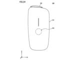
- FIG. 2A is a front view of the suction device 100.
- FIG. 2B is a top view of the suction device 100.
- FIG. 2C is a bottom view of the suction device 100.
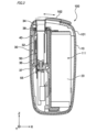
- FIG. 3 is a cross-sectional view of the suction device 100 taken along the line 3-3 shown in FIG. 2B.
- FIG. 4A is a perspective view of the chamber 50.
- FIG. 4B is a cross-sectional view of chamber 50 taken along line 4B-4B shown in FIG. 4A.
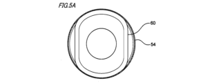
- FIG. 5A is a cross-sectional view of chamber 50 taken along line 5A-5A shown in FIG. 4B.
- FIG. 5B is a cross-sectional view of chamber 50 taken along line 5B-5B shown in FIG. 4B.
- FIG. 6 is a perspective view of the chamber 50 and the heater 40.
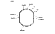
- FIG. 7 is a cross-sectional view of the substrate stick 150 shown in FIG. 5B, positioned in a heated position within the chamber 50.
- FIG. 8 is a perspective view showing an air flow path in the suction device 100.
- FIG. 9 is an enlarged cross-sectional view of the periphery of the first holding portion 37.
- FIG. 10 is a diagram showing an example of the characteristics of the pressure sensor 55.
- FIG. 11 is a diagram showing a first example of a time series transition of the electrical resistance value of the pressure sensor 55.
- FIG. 12 is a diagram showing a second example of the time series transition of the electrical resistance value of the pressure sensor 55.
- FIG. 13 is a diagram showing a third example of the time series transition of the electrical resistance value of the pressure sensor 55.
- FIG. FIG. 14 is a diagram showing an example of a heating profile in this embodiment.
- FIG. 15 is a flowchart showing an example of processing executed by the control unit 116.
- FIG. 16 is a diagram showing another example (part 1) of the arrangement of the pressure sensor 55.
- FIG. 17 is a diagram showing another example (part 2) of the arrangement of the pressure sensor 55.
- FIG. FIG. 18 is a diagram showing another example (part 3) of the arrangement of the pressure sensor 55.
- FIG. 16 is a diagram showing another example (part 1) of the arrangement of the pressure sensor 55.
- FIG. 17 is a diagram showing another example (part 2) of the arrangement of the pressure sensor 55.
- FIG. FIG. 18 is a diagram showing another example (part 3) of the arrangement of the pressure sensor 55
- the aerosol generating device of the present disclosure will be described in detail.
- the following embodiment is an example of the application of the aerosol generating device of the present disclosure to an inhalation device. Note that the following embodiment does not limit the invention described in the claims, and not all of the features described in the following embodiment are necessarily essential. Furthermore, two or more of the multiple features described in the following embodiment may be combined in any combination. Also, below, identical or similar elements are denoted with identical or similar reference symbols, and their descriptions will be omitted or simplified as appropriate.
- the inhalation device of the present embodiment which is an example of the aerosol generating device of the present disclosure, is a device that generates a substance to be inhaled by a user.
- the substance generated by the inhalation device of the present embodiment will be described as an aerosol, but this is not limited thereto, and for example, the substance generated may be a gas.
- Fig. 1 is a schematic diagram showing an example of the suction device 100 of this embodiment.
- the suction device 100 includes a power supply unit 111, a sensor unit 112, a notification unit 113, a storage unit 114, a communication unit 115, a control unit 116, a heating unit 121, a storage unit 140, and a heat insulating unit 144.
- the power supply unit 111 accumulates power.
- the power supply unit 111 supplies power to each component of the suction device 100 based on the control of the control unit 116.
- the power supply unit 111 may be configured to be rechargeable by power received from an external power source (not shown).
- the power supply unit 111 is configured, for example, by a rechargeable battery such as a lithium ion secondary battery.
- the sensor unit 112 acquires various information related to the suction device 100.
- the sensor unit 112 includes, for example, a pressure sensor such as a strain gauge or a condenser microphone, a flow sensor, or a temperature sensor such as a thermistor, and acquires values associated with the user's suction.
- the sensor unit 112 includes a pressure sensor 55 that outputs a value related to the pressure generated when the stick-shaped substrate 150 (described below) contained in the storage unit 140 is pressed in the insertion direction.
- the pressure sensor 55 may also output a value related to the pressure generated when the stick-shaped substrate 150 is inserted into the storage unit 140. Details of the pressure sensor 55 will be described later, so a description thereof will be omitted here.
- the sensor unit 112 may also include an input device, such as an operation button or an operation switch, that accepts information input (in other words, operation) from the user.
- an input device such as an operation button or an operation switch, that accepts information input (in other words, operation) from the user.
- An example of this input device may be the switch of the switch unit 103, which will be described later.
- the notification unit 113 notifies the user of information.
- the notification unit 113 is configured, for example, by a light-emitting device that emits light, a display device that displays an image, a sound output device that outputs sound, or a vibration device that vibrates.
- the light-emitting device can be realized, for example, by a light-emitting element such as an LED (Light-Emitting Diode) and a drive circuit that causes the light-emitting element to emit light.
- the display device can be, for example, a liquid crystal display or an OLED display (OLED: Organic Light Emitting Diode).
- the sound output device can be, for example, a speaker.
- the vibration device can be, for example, a vibrator configured to include a motor and an eccentric weight attached to the rotating shaft of the motor.
- the storage unit 114 stores various information (e.g., programs and data) required for the operation of the suction device 100.
- the storage unit 114 is configured, for example, from a non-volatile storage medium such as a flash memory.
- the communication unit 115 is a communication interface capable of performing communication conforming to any wired or wireless communication standard.
- Such communication standards include, for example, standards using Wi-Fi (registered trademark), Bluetooth (registered trademark), BLE (Bluetooth Low Energy, registered trademark), NFC (Near Field Communication), or LPWA (Low Power Wide Area).
- the control unit 116 functions as an arithmetic processing unit and a control unit, and controls the overall operation of the suction device 100 in accordance with various programs stored in the memory unit 114, etc.
- the control unit 116 controls the power supply from the power supply unit 111 to each component including the heating unit 121 described below.
- the control unit 116 is realized by, for example, an electronic circuit such as a CPU (Central Processing Unit) or a microprocessor.
- the control unit 116 can be realized by an MCU (Micro Controller Unit).
- the storage section 140 has an internal space 141, and holds the stick-shaped substrate 150 while storing a portion of the stick-shaped substrate 150 in the internal space 141.
- the storage section 140 has an opening 142 at one end that connects the internal space 141 to the outside, and stores the stick-shaped substrate 150 inserted into the internal space 141 through the opening 142.
- the storage section 140 has an opening 142 at one end, and stores a portion of the stick-shaped substrate 150 inserted through the opening 142.
- the storage section 140 is a cylindrical body with an opening 142 and a bottom section 143 as its bottom surface, and defines a columnar internal space 141. Air is supplied to the stick-shaped substrate 150 stored in the storage section 140 via an air flow path provided in or connected to the internal space 141. An example of this air flow path will be described later with reference to FIG. 8, etc.
- the stick-type substrate 150 is an example of a substrate containing an aerosol source, and is configured to include a substrate portion 151 and a mouthpiece portion 152.
- the substrate portion 151 includes an aerosol source.
- the aerosol source includes a flavor component derived from tobacco or a non-tobacco.
- the aerosol source may include a medicine.
- the aerosol source may be a liquid such as polyhydric alcohols such as glycerin and propylene glycol, which include a flavor component derived from tobacco or a non-tobacco, and water, or may be a solid which includes a flavor component derived from tobacco or a non-tobacco.
- the stick-shaped substrate 150 When the stick-shaped substrate 150 is held (in other words, stored) in the storage section 140, at least a portion of the substrate section 151 is stored in the internal space 141, and at least a portion of the suction mouth section 152 protrudes from the opening 142.
- a user holds the suction mouth section 152 protruding from the opening 142 in their mouth and inhales, air flows into the internal space 141 via the air flow path described above, and reaches the user's mouth together with the aerosol generated from the substrate section 151.
- the heating unit 121 generates an aerosol by heating the aerosol source and atomizing the aerosol source.
- the heating unit 121 is configured as a film heater with a conductive track (i.e., a heating track) made up of a heating resistor having a correlation between electrical resistance and temperature, and is arranged to cover the outer periphery of the storage unit 140.
- the heating unit 121 generates heat when power is supplied from the power supply unit 111.
- the heating unit 121 When the heating unit 121 generates heat while the stick-shaped substrate 150 is inserted into the storage unit 140 (in other words, the internal space 141), the substrate portion 151 of the stick-shaped substrate 150 is heated from the outer periphery, and an aerosol is generated.
- the heating resistor of the heating section 121 may be made of a material having a PTC (Positive Temperature Coefficient) characteristic, in which the electrical resistance increases in proportion to the rise in temperature, such as nichrome or stainless steel.
- PTC Pressure Temperature Coefficient
- the insulating section 144 prevents heat transfer from the heating section 121 to other components.
- the insulating section 144 is made of a vacuum insulating material, an aerogel insulating material, or the like.
- the configuration of the suction device 100 is not limited to the above, and various configurations such as those exemplified below are possible.
- the heating unit 121 may be configured in a blade shape and disposed so as to protrude from the bottom 143 of the storage unit 140 into the internal space 141.
- the blade-shaped heating unit 121 is inserted into the substrate 151 of the stick-shaped substrate 150 and heats the substrate 151 of the stick-shaped substrate 150 from the inside.
- the heating unit 121 may be disposed so as to cover the bottom 143 of the storage unit 140.
- the heating unit 121 may be configured as a combination of two or more of a first heating unit that covers the outer periphery of the storage unit 140, a blade-shaped second heating unit, and a third heating unit that covers the bottom 143 of the storage unit 140.
- the storage unit 140 may include an opening/closing mechanism such as a hinge that opens and closes a portion of the outer shell that forms the internal space 141. The storage unit 140 may then open and close the outer shell to accommodate the stick-shaped substrate 150 inserted into the internal space 141 while clamping it.
- the heating unit 121 may be provided at the clamping location in the storage unit 140, and may heat the stick-shaped substrate 150 while pressing it.
- the means for atomizing the aerosol source may also be induction heating.
- the suction device 100 has at least an electromagnetic induction source such as a coil that generates a magnetic field, instead of the heating unit 121.
- a susceptor that generates heat by induction heating may be provided in the suction device 100, or may be included in the stick-shaped substrate 150.
- suction by the user onto the suction device 100 will also be referred to as a "puff.”
- FIG. 2A is a front view of the suction device 100.
- FIG. 2B is a top view of the suction device 100.
- FIG. 2C is a bottom view of the suction device 100.
- the drawings used in the following explanation may be accompanied by an X-Y-Z Cartesian coordinate system.
- the Z axis faces vertically upward, the X-Y plane is arranged to cut the suction device 100 horizontally, and the Y axis is arranged to extend from the front to the back of the suction device 100.
- the Z axis can also be referred to as the insertion direction of the stick-shaped substrate 150 contained in the chamber 50 described later, or the axial direction of the chamber 50.
- the X axis is a direction perpendicular to the Y axis and the Z axis, and the X axis and the Y axis can also be referred to as the radial direction perpendicular to the axial direction, or the radial direction of the chamber 50.
- the suction device 100 has an outer housing 101, a slide cover 102, and a switch unit 103.
- the outer housing 101 constitutes the outermost housing of the suction device 100 and has a size that fits in the user's hand.
- the user can hold the suction device 100 in their hand and inhale aerosol (i.e., puff).
- the outer housing 101 is formed, for example, by assembling multiple members.
- the members that constitute the outer housing 101 can be made of various resins such as polycarbonate, ABS (Acrylonitrile-Butadiene-Styrene) resin, or PEEK (Poly Ether Ether Ketone), or various metals such as aluminum or stainless steel.
- the outer housing 101 has an opening (not shown) for receiving the stick-shaped substrate 150, and the slide cover 102 is slidably attached to the outer housing 101 so as to close the opening.
- the slide cover 102 is configured to be movable along the outer surface of the outer housing 101 between a closed position (position shown in FIG. 2A and FIG. 2B) in which the opening of the outer housing 101 is closed and an open position in which the opening is opened.
- a closed position position shown in FIG. 2A and FIG. 2B
- the access of the stick-shaped substrate 150 to the inside of the suction device 100 e.g., inside the storage section 140
- the slide cover 102 when the slide cover 102 is in the open position, the access of the stick-shaped substrate 150 to the inside of the suction device 100 (e.g., inside the storage section 140) is permitted.
- the slide cover 102 is an example of a cover member in the present disclosure.
- the user can manually operate the slide cover 102 to move the slide cover 102 between the closed position and the open position.
- the switch unit 103 is used to switch the operation of the suction device 100 on and off. As an example, when the switch unit 103 is operated with the stick-shaped substrate 150 inserted in the suction device 100, power may be supplied to the heating member 42, which will be described later, to heat the stick-shaped substrate 150.
- the switch unit 103 may be a switch provided outside the outer housing 101, or may be a switch located inside the outer housing 101. If the switch is located inside the outer housing 101, the switch is indirectly pressed by pressing the switch unit 103 on the surface of the outer housing 101.
- the suction device 100 may further have a terminal (not shown).
- This terminal functions, for example, as an interface that electrically connects the suction device 100 to an external power source.
- This terminal may also be used to connect the suction device 100 to an external device (for example, a user's smartphone).
- an external device for example, a user's smartphone.
- a data transmission cable may be connected to this terminal, and the suction device 100 and the external device may be connected via the data transmission cable, so that data related to the operation of the suction device 100 and the like may be transmitted and received between the suction device 100 and the external device.
- FIG. 3 is a cross-sectional view of the suction device 100 taken along the line 3-3 in FIG. 2B.
- an inner housing 10 is provided inside an outer housing 101 of the suction device 100.
- the inner housing 10 may be made of, for example, any of the various resins mentioned above.
- a power source 20 and an atomization unit 30 are provided in the internal space of the inner housing 10.
- the power source 20 is, for example, a rechargeable battery that constitutes the power source unit 111 described above, and is electrically connected to the atomization unit 30. This allows the power source 20 to supply power to the atomization unit 30.
- the atomization section 30 has a chamber 50, a heater 40 that covers part of the chamber 50, a heat insulating section 32, and a generally cylindrical insertion guide member 34 that abuts against the opening 52 of the chamber 50 (see FIG. 4A).
- the chamber 50 is a cylindrical member that extends in the insertion direction (Z-axis direction) of the stick-shaped substrate 150 and is configured so that the stick-shaped substrate 150 can be inserted therein.
- the heater 40 is provided so as to be in contact with the outer peripheral surface of the chamber 50, and includes a heating member 42 (see FIG. 6) that heats the stick-shaped substrate 150 inserted into the chamber 50.
- a bottom member 36 is provided at the bottom of the chamber 50 as a component constituting the bottom 143 described above.
- the bottom member 36 is provided at the bottom of the chamber 50, and functions as a stopper that positions the stick-shaped substrate 150 within the chamber 50 by abutting against an end of the stick-shaped substrate 150 contained in the chamber 50.
- the aforementioned container 140 is, for example, composed of the chamber 50 and the bottom member 36.
- the bottom member 36 also has projections and recesses on the contact surface 36c (see FIG. 9) with the stick-shaped substrate 150. Due to these projections and recesses, a first air flow path AF1 (see FIG. 8) that communicates with the stick-shaped substrate 150 is formed on the contact surface 36c of the bottom member 36 with the stick-shaped substrate 150.
- the bottom member 36 also functions as a movable member that moves in the insertion direction when the stick-shaped substrate 150 contained in the chamber 50 is pressed in the insertion direction.
- the bottom member 36 is made of, for example, various resins as described above. It is preferable that the bottom member 36 is made of a material with low thermal conductivity to prevent heat from being transferred to the insulating portion 32, etc.
- the insulating section 32 for example, constitutes the insulating section 144 described above.
- the insulating section 32 is generally cylindrical and is disposed so as to cover the chamber 50.
- the insulating section 32 for example, is configured to include an aerogel sheet.
- the insertion guide member 34 is provided between the chamber 50 and an opening in the outer housing 101 for receiving the stick-shaped substrate 150, and is provided in contact with the opening 52 of the chamber 50 to guide the insertion of the stick-shaped substrate 150 into the chamber 50.
- the insertion guide member 34 is made of, for example, various resins as described above. From the standpoint of heat resistance, it is preferable that the insertion guide member 34 be made of PEEK.
- the suction device 100 further has a first holding part 37 and a second holding part 38 that hold both ends of the chamber 50 and the insulating part 32.
- the first holding part 37 is positioned so as to hold the ends of the chamber 50 and the insulating part 32 on the negative Z-axis side.
- the second holding part 38 is positioned so as to hold the ends of the chamber 50 and the insulating part 32 on the slide cover 102 side (positive Z-axis side).
- the suction device 100 further includes the pressure sensor 55 described above.
- This pressure sensor 55 is provided, for example, in the insertion direction of the stick-shaped substrate 150 so as to face the tip surface 36d (see FIG. 9) of the bottom member 36 opposite the abutment surface 36c with the stick-shaped substrate 150.
- the pressure sensor 55 is provided in contact with the tip surface 36d of the bottom member 36, and outputs a value related to the pressure generated by being pressed by the bottom member 36 moving in the insertion direction.
- Fig. 4A is a perspective view of the chamber 50.
- Fig. 4B is a cross-sectional view of the chamber 50 taken along line 4B-4B in Fig. 4A.
- Fig. 5A is a cross-sectional view of the chamber 50 taken along line 5A-5A in Fig. 4B.
- Fig. 5B is a cross-sectional view of the chamber 50 taken along line 5B-5B in Fig. 4B.
- Fig. 6 is a perspective view of the chamber 50 and the heater 40.
- the chamber 50 is, for example, a cylindrical member including an opening 52 into which the stick-shaped substrate 150 is inserted, and a cylindrical side wall portion 60 that houses the stick-shaped substrate 150.
- the chamber 50 is preferably made of a material that is heat resistant and has a small coefficient of thermal expansion, for example, stainless steel. This allows for effective heating from the chamber 50 to the stick-shaped substrate 150.
- the chamber 50 may be made of a resin such as PEEK, glass, ceramic, or the like, in addition to metal.
- the side wall portion 60 includes a contact portion 62 and a separation portion 66.
- the contact portion 62 contacts or presses a part of the stick-shaped substrate 150 in a plane intersecting the insertion direction of the stick-shaped substrate 150, and the separation portion 66 is separated from the stick-shaped substrate 150.
- the heating position here refers to a position where the stick-shaped substrate 150 is appropriately heated, or the position of the stick-shaped substrate 150 when the user smokes using the inhalation device 100.
- the sidewall portion 60 includes the contact portion 62 and the separation portion 66, the cross-sectional shape of the sidewall portion 60 perpendicular to the axial direction (Z-axis direction) of the chamber 50 is elliptical, i.e., non-cylindrical.
- the storage portion 140 is composed of the chamber 50 and the bottom member 36 formed of a material different from the chamber 50, even if the chamber 50 has an irregular shape such as an elliptical or rectangular cylindrical shape, fine processing can be performed on the bottom member 36 regardless of the shape of the chamber 50, and the processability of the storage portion 140 can be improved.
- the contact portion 62 has an inner surface 62a and an outer surface 62b.
- the separation portion 66 has an inner surface 66a and an outer surface 66b.
- the heater 40 is disposed on the outer surface 62b of the contact portion 62. This allows heat generated by the heating member 42 of the heater 40 to be transferred to the stick-shaped substrate 150 in contact with the contact portion 62.
- the heater 40 is preferably disposed without gaps on the outer surface 62b of the contact portion 62.
- the heater 40 may include an adhesive layer. In that case, it is preferable that the heater 40 including the adhesive layer is disposed without gaps on the outer surface 62b of the contact portion 62.
- the outer surface 62b of the contact portion 62 is flat. Because the outer surface 62b of the contact portion 62 is flat, bending of the band-shaped electrode 48 can be suppressed when the band-shaped electrode 48 is connected to the heater 40 arranged on the outer surface 62b of the contact portion 62 as shown in Figure 6. As shown in Figures 4B and 5B, the inner surface 62a of the contact portion 62 is flat. Also, as shown in Figures 4B and 5B, the thickness of the contact portion 62 is uniform.
- the chamber 50 has two contact portions 62 in the circumferential direction of the chamber 50, and the two contact portions 62 face each other so as to be parallel to each other. It is preferable that at least a portion of the distance between the inner surfaces 62a of the two contact portions 62 is smaller than the width of the portion of the stick-shaped substrate 150 inserted into the chamber 50 that is located between the contact portions 62.
- the inner surface 66a of the spaced portion 66 may have an overall arc-shaped cross section in a plane perpendicular to the axial direction (Z-axis direction) of the chamber 50.
- the spaced portion 66 is disposed so as to be adjacent to the contact portion 62 in the circumferential direction.
- the chamber 50 has a hole 56a in its bottom 56 so that the bottom member 36 shown in FIG. 3 can pass through and be positioned inside the chamber 50.
- the bottom member 36 is provided inside the bottom 56 of the chamber 50.
- the bottom member 36 provided on the bottom 56 supports a portion of the stick-shaped substrate 150 inserted into the chamber 50 so that at least a portion of the end face of the stick-shaped substrate 150 is exposed.
- the bottom 56 supports a portion of the stick-shaped substrate 150 so that the exposed end face of the stick-shaped substrate 150 communicates with a void 67 (see FIG. 7) described below.
- the chamber 50 preferably has a cylindrical non-holding portion 54 between the opening 52 and the sidewall portion 60.
- a gap may be formed between the non-holding portion 54 and the stick-shaped substrate 150.
- the chamber 50 preferably has a first guide portion 58 with a tapered surface 58a that connects the inner surface of the non-holding portion 54 and the inner surface 62a of the contact portion 62.
- the heater 40 has a heating member 42 constituting the heating section 121 described above.
- the heating member 42 can be, for example, a film heater provided with a heating track.
- the heating member 42 is preferably arranged so as to heat the contact section 62 without contacting the separated section 66 of the chamber 50.
- the heating member 42 is preferably arranged only on the outer surface of the contact section 62.
- the heating member 42 may have a difference in heating capacity between a portion that heats the separated section 66 of the chamber 50 and a portion that heats the contact section 62.
- the heating member 42 may be configured to heat the contact section 62 to a higher temperature than the separated section 66.
- the arrangement density of the heating track of the heating member 42 in the contact section 62 and the separated section 66 may be adjusted.
- the heating member 42 may have substantially the same heating capacity over the entire circumference of the chamber 50 and may be wound around the outer periphery of the chamber 50.
- the heater 40 preferably has, in addition to the heating member 42, an electrical insulating member 44 that covers at least one side of the heating member 42.
- the electrical insulating member 44 is arranged so as to cover both sides of the heating member 42.
- the bottom member 36 can be arranged so as not to overlap with the heating member 42 in the axial direction of the chamber 50. This makes it difficult for heat from the heating member 42 to be transferred to the bottom member 36, and deterioration of the bottom member 36 due to heat can be suppressed.
- FIG. 7 is a cross-sectional view of the state shown in FIG. 5B in which the stick-shaped substrate 150 is placed at the heating position in the chamber 50.
- the stick-shaped substrate 150 comes into contact with the contact portion 62 of the chamber 50 and is pressed.
- a gap 67 is formed between the stick-shaped substrate 150 and the separation portion 66.
- the gap 67 communicates with the opening 52 of the chamber 50 and the end face of the stick-shaped substrate 150 positioned in the chamber 50.
- air flowing in from the opening 52 of the chamber 50 can pass through the gap 67 and flow into the inside of the stick-shaped substrate 150.
- a second air flow path (gap 67) is formed between the stick-shaped substrate 150 and the separation portion 66.
- FIG. 8 is a perspective view showing an air flow path in the suction device 100. Note that the stick-type substrate 150 is omitted from Fig. 8. As shown in Fig. 8, the second air flow path AF2 formed between the stick-type substrate 150 and the separating portion 66 communicates with the first air flow path AF1 formed in the bottom member 36, and the first air flow path AF1 communicates with the third air flow path AF3 passing through the inside of the stick-type substrate 150.
- the air introduced into the storage section 140 composed of the chamber 50 and the bottom member 36 is supplied to the stick-type substrate 150 through the second air flow path AF2 and the first air flow path AF1, and then reaches the user's mouth, so there is no need to provide a separate flow path in the inhalation device 100 for introducing the air supplied to the stick-type substrate 150.
- FIG. 9 is an enlarged cross-sectional view of the periphery of the first holding portion 37.
- the bottom member 36 engages with the bottom 56 of the chamber 50. This allows the bottom member 36 to be positioned and supported within the chamber 50.
- the bottom member 36 provided on the bottom 56 of the chamber 50 has a shaft portion 36a that protrudes to the outside of the chamber 50 through a hole 56a of the chamber 50.
- a flat surface 36b is provided on a portion of the outer circumferential surface of the shaft portion 36a.
- the first retaining portion 37 has a support portion 72, which is an example of a support portion in this disclosure, a heater cushion 74, which is another example of a support portion in this disclosure, and a ring 85.
- the support portion 72 is configured to receive the shaft portion 36a of the bottom member 36 and support the chamber 50. Specifically, the bottom portion 56 of the chamber 50 is supported by being sandwiched between the bottom member 36 and the support portion 72.
- the support portion 72 is made of, for example, various resins, metals, glass, ceramics, etc., as described above. From the standpoint of heat resistance, it is preferable that the support portion 72 is made of PEEK.
- the support portion 72 has a flat surface 72a that faces the flat surface 36b of the shaft portion 36a.
- the flat surface 36b of the shaft portion 36a and the flat surface 72a of the support portion 72 engage with each other, thereby preventing the support portion 72 from rotating relative to the chamber 50.
- the bottom member 36 also has a tip surface 36d as the surface opposite the contact surface 36c that contacts the stick-shaped substrate 150 inserted into the chamber 50, more specifically, as the end surface on the negative Z-axis direction side of the shaft portion 36a.
- the pressure sensor 55 is disposed, for example, facing the tip surface 36d in the insertion direction of the stick-shaped substrate 150 (i.e., the Z-axis direction) and in contact with the tip surface 36d.
- the pressure sensor 55 is provided, for example, on a chassis member 200 that is harder than the pressure sensor 55.
- the chassis member 200 is, for example, a skeletal member of the suction device 100, and is made of, for example, metal. In this way, it is possible to suppress displacement of the pressure sensor 55 when pressed, compared to when the pressure sensor 55 is provided on a soft member.
- the chassis member 200 is fixed to the inner housing 10 described above, for example, by a fixing portion (not shown).
- the chassis member 200 may also be part of the inner housing 10.
- the heater cushion 74 accommodates and supports one end of the support portion 72, and has a hole 74a at approximately the center when viewed from the Z-axis direction through which the shaft portion 36a of the bottom member 36 passes.
- the heater cushion 74 is made of an elastic material such as silicon, and supports the chamber 50 and bottom member 36 via the support portion 72, and urges them in the positive direction of the Z-axis.
- the heater cushion 74 is positioned and fixed, for example, to the fixing portion 22 fixed to the inner housing 10 described above.
- the fixing portion 22 may be the inner housing 10 itself.
- the ring 85 has an opening 85a into which the support portion 72 is inserted, and is fixed by being sandwiched between the support portion 72 and the heater cushion 74.
- the ring 85 is made of, for example, various resins, metals, glass, ceramics, etc., as described above. From the viewpoint of heat resistance, it is preferable that the ring 85 is made of PEEK.
- the ring 85 is arranged to face the support material 32a (described later) provided on the inner surface of the insulating part 32 with a gap therebetween, and restricts the movement of the insulating part 32 in the radial direction of the chamber 50. This prevents the insulating part 32 from moving endlessly in the radial direction of the chamber 50, thereby preventing the insulating part 32 from colliding with other members (e.g., the inner housing 10). In addition, because the movement of the insulating part 32 in the radial direction of the chamber 50 can be restricted from inside the insulating part 32, the suction device 100 can be made smaller.
- the heat insulating section 32 has a support material 32a and a heat insulating layer 32b provided on the outer peripheral surface of the support material 32a.
- the support material 32a is, for example, substantially cylindrical, and is arranged to surround the chamber 50.
- the support material 32a is, for example, made of various resins as described above.
- the heat insulating layer 32b can be, for example, an aerogel sheet.
- the support material 32a is preferably formed thinner than the heat insulating layer 32b (for example, with a thickness of 1 mm or less). In this way, the heat capacity of the heat insulating section 32 itself can be reduced, making it possible to suppress heat loss in the heat insulating section 32.
- the pressure sensor 55 outputs a value (parameter) related to pressure.
- the pressure is, for example, a force applied to the pressure sensor 55 from the outside.
- the pressure sensor 55 is configured with a strain gauge such as a metal strain gauge or a semiconductor strain gauge, and outputs the electrical resistance value of its own resistor as a value related to pressure.
- the output value of the pressure sensor 55 is input to the MCU or the like constituting the control unit 116 described above. This allows the control unit 116 to acquire the output value of the pressure sensor 55.
- FIG. 10 is a diagram showing an example of the characteristics of pressure sensor 55.
- the vertical axis represents the electrical resistance value [ ⁇ ] of pressure sensor 55
- the horizontal axis represents pressure [N].
- the electrical resistance value of pressure sensor 55 decreases as the pressure increases.
- the electrical resistance value of pressure sensor 55 is Ra [ ⁇ ] (where Ra > 0)
- the electrical resistance value of pressure sensor 55 is Rb [ ⁇ ] (where 0 ⁇ Rb ⁇ Ra).
- FIG. 11 is a diagram showing a first example of a time series transition of the electrical resistance value of the pressure sensor 55.
- the first example described here is an example in which the user puffs.
- the vertical axis represents the electrical resistance value [ ⁇ ] of the pressure sensor 55
- the horizontal axis represents the time.
- times t1, t2, t3, t4, and t5 are the times when the user puffs.
- the user holds the stick-shaped substrate 150 contained in the chamber 50 in their mouth.
- the stick-shaped substrate 150 is pressed in the chamber 50 towards the negative Z-axis direction, which is the insertion direction.
- the bottom member 36 that contacts the stick-shaped substrate 150 inside the chamber 50 is also pressed toward the negative Z-axis direction, and can move slightly toward the negative Z-axis direction against the biasing force of the heater cushion 74 toward the positive Z-axis direction.
- the tip surface 36d of the bottom member 36 presses against the pressure sensor 55, generating a greater pressure than before the puff was performed.
- the electrical resistance value of the pressure sensor 55 at times t1, t2, t3, t4, and t5 becomes smaller than the predetermined value R1 [ ⁇ ].
- the above-mentioned increase in pressure does not occur, and the electrical resistance value of the pressure sensor 55 becomes larger than R1 [ ⁇ ].
- FIG. 12 is a diagram showing a second example of the time series transition of the electrical resistance value of the pressure sensor 55.
- the second example described here is an example in which the user inserts the stick-type substrate 150 into the chamber 50.
- dirt such as tobacco leaves that have fallen from the stick-type substrate 150 and/or condensed aerosol may adhere to the inside of the chamber 50, but in the second example described here, it is assumed that there is no dirt in the chamber 50.
- the vertical axis represents the electrical resistance value [ ⁇ ] of the pressure sensor 55
- the horizontal axis represents the time.
- time t11 is the time when the user inserts the stick-shaped substrate 150 into the chamber 50.
- the stick-shaped substrate 150 is pressed in the chamber 50 toward the negative Z-axis direction, which is the insertion direction.
- the bottom member 36 is also pressed toward the negative Z-axis direction and can move slightly toward the negative Z-axis direction against the biasing force of the heater cushion 74 toward the positive Z-axis direction. Then, when the bottom member 36 moves toward the negative Z-axis direction, the tip surface 36d of the bottom member 36 presses against the pressure sensor 55, generating a larger pressure than before the stick-shaped substrate 150 was inserted into the chamber 50.
- the electrical resistance value of the pressure sensor 55 at time t11 becomes smaller than the predetermined value R2 [ ⁇ ].
- R2 [ ⁇ ] the predetermined value
- time t12 is the time when the user removes the stick-shaped substrate 150 from the chamber 50.
- the stick-shaped substrate 150 moves within the chamber 50 in the positive Z-axis direction, which is the opposite direction to the insertion direction.
- the bottom member 36 moves slightly in the positive direction of the Z axis due to the biasing force of the heater cushion 74 in the positive direction of the Z axis. Then, when the bottom member 36 moves in the positive direction of the Z axis, the force (i.e., pressure) with which the tip surface 36d of the bottom member 36 presses against the pressure sensor 55 decreases. Due to this decrease in pressure associated with the removal of the stick-shaped substrate 150, the electrical resistance value of the pressure sensor 55 at time t12 becomes greater than a predetermined value R3 [ ⁇ ] (where R3 > R2).
- FIG. 13 is a diagram showing a third example of the time series transition of the electrical resistance value of the pressure sensor 55.
- the third example described here is an example in which the user inserts the stick-shaped substrate 150 into the chamber 50, similar to the second example shown in Fig. 12, but differs from the second example described above in that the inside of the chamber 50 is dirty. Note that the following description will focus on the differences from the second example shown in Fig. 12, and descriptions of similar points will be omitted or simplified as appropriate.
- time t21 is the time when the user inserts the stick-shaped substrate 150 into the chamber 50.
- the electrical resistance value of the pressure sensor 55 decreases due to the increase in pressure that accompanies the insertion. If the inside of the chamber 50 is dirty when the stick-shaped substrate 150 is inserted, the dirt narrows the internal space of the chamber 50, and a greater force is required to insert the stick-shaped substrate 150. For this reason, when the inside of the chamber 50 is dirty, the user presses the stick-shaped substrate 150 more strongly in the negative Z-axis direction when inserting the stick-shaped substrate 150 into the chamber 50 than when the inside of the chamber 50 is not dirty.
- the range from R2 [ ⁇ ] to R4 [ ⁇ ] is also referred to as the "first range RG1," and the range smaller than R4 [ ⁇ ] is also referred to as the "second range RG2.”
- time t22 is the time when the user removes the stick-shaped substrate 150 from the chamber 50.
- the electrical resistance value of the pressure sensor 55 becomes greater than R3 [ ⁇ ] due to the reduction in pressure that accompanies the removal.
- the control unit 116 can control the operation of the suction device 100 based on the output value of the pressure sensor 55. As an example, the control unit 116 detects that the stick-type substrate 150 has been inserted into the chamber 50 (i.e., the storage unit 140) based on the output value of the pressure sensor 55. This makes it possible to detect that the stick-type substrate 150 has been inserted into the chamber 50 by utilizing the pressure sensor 55.
- the control unit 116 acquires the electrical resistance value, which is the output value of the pressure sensor 55, at a predetermined cycle (for example, every 5 [ms]), and detects that the stick-shaped substrate 150 has been inserted into the chamber 50 when the electrical resistance value transitions from a state greater than R2 [ ⁇ ] to a state less than R2 [ ⁇ ]. That is, the control unit 116 detects that the stick-shaped substrate 150 has been inserted into the chamber 50 based on the time series transition of the output value of the pressure sensor 55. This makes it possible to accurately detect that the stick-shaped substrate 150 has been inserted into the chamber 50 based on the output value (electrical resistance value) of the pressure sensor 55, which is easily available, such as a strain gauge. In this case, R2 [ ⁇ ] is set in advance, for example, by the manufacturer of the suction device 100.
- control unit 116 may be configured to start heating by the heating unit 121 when it detects that the stick-shaped substrate 150 has been inserted into the chamber 50.
- control unit 116 may be configured to start heating control, which will be described later, when it detects that the stick-shaped substrate 150 has been inserted into the chamber 50.
- the output value of the pressure sensor 55 when the stick-shaped substrate 150 is inserted into the chamber 50 may differ depending on whether the inside of the chamber 50 is dirty or not.
- the control unit 116 may further determine whether or not the inside of the chamber 50 is dirty based on the output value of the pressure sensor 55 when it detects that the stick-shaped substrate 150 has been inserted into the chamber 50. In this way, it is possible to use the pressure sensor 55 to determine whether or not the inside of the chamber 50 is dirty.
- control unit 116 may acquire the electrical resistance value, which is the output value of the pressure sensor 55, at a predetermined period, and when the electrical resistance value transitions from a state greater than R2 [ ⁇ ] to be included in the first range RG1 shown in FIG. 13, detect that the stick-shaped substrate 150 has been inserted into the chamber 50 and determine that the inside of the chamber 50 is not dirty.
- control unit 116 may detect that the stick-shaped substrate 150 has been inserted into the chamber 50 and determine that the inside of the chamber 50 is dirty.
- R2 [ ⁇ ] and R4 [ ⁇ ], i.e., the first range RG1 and the second range RG2, are set in advance, for example, by the manufacturer of the suction device 100, etc.
- the control unit 116 may start heating by the heating unit 121 when it is determined that the inside of the chamber 50 is not dirty, and may not perform heating by the heating unit 121 when it is determined that the inside of the chamber 50 is dirty. In other words, the control unit 116 may perform heating by the heating unit 121 when the output value of the pressure sensor 55 when the stick-shaped substrate 150 is inserted into the chamber 50 is within the first range RG1, but may not perform heating by the heating unit 121 when it is within the second range RG2 (in other words, not within the first range RG1). In this way, heating by the heating unit 121 can be prevented when the inside of the chamber 50 is dirty, and heating by the heating unit 121 can be appropriately performed taking into account the state inside the chamber 50.
- the heating unit 121 when the inside of the chamber 50 is dirty, poor quality aerosol or smoke may be generated due to the dirt inside the chamber 50, or the dirt may become more firmly attached inside the chamber 50 and become difficult to remove. If such a situation occurs, it may cause discomfort to the user and reduce the quality of the experience provided to the user by the suction device 100.
- control unit 116 determines that the inside of the chamber 50 is dirty, it is possible to prevent the occurrence of the above-mentioned situation by preventing heating by the heating unit 121. Therefore, it is possible to prevent the occurrence of the above-mentioned situation, which would result in a decrease in the quality of the experience provided to the user by the suction device 100.
- control unit 116 may notify the user that the inside of the chamber 50 is dirty and/or that cleaning of the inside of the chamber 50 is necessary via the notification unit 113 that can notify the user of information. In this way, the user can be prompted to check the inside of the chamber 50 when it is determined that the inside of the chamber 50 is dirty, and also the user can be prompted to clean the inside of the chamber 50 if the inside of the chamber 50 is actually dirty.
- the control unit 116 may notify the user that the inside of the chamber 50 is dirty and/or that the inside of the chamber 50 needs to be cleaned by making the light-emitting device emit light in a predetermined light-emitting mode.
- the predetermined light-emitting mode can be, for example, a light-emitting mode used only when notifying the user that the inside of the chamber 50 is dirty and/or that the inside of the chamber 50 needs to be cleaned, in other words, a light-emitting mode different from a light-emitting mode that indicates other errors or states of the suction device 100.
- the light-emitting mode refers to a light-emitting color, a light-emitting number (e.g., the number of light-emitting elements that emit light), a light-emitting pattern (e.g., blinking), or the like. This makes it possible to notify the user that the inside of the chamber 50 is dirty and/or that the inside of the chamber 50 needs to be cleaned in an intuitive and easy-to-understand manner.
- a light-emitting number e.g., the number of light-emitting elements that emit light
- a light-emitting pattern e.g., blinking
- the control unit 116 may vibrate the vibration device in a predetermined vibration mode to notify the user that the inside of the chamber 50 is dirty and/or that the inside of the chamber 50 needs to be cleaned.
- the predetermined vibration mode can be, for example, a vibration mode that is used only when notifying the user that the inside of the chamber 50 is dirty and/or that the inside of the chamber 50 needs to be cleaned, in other words, a vibration mode that is different from the vibration mode that indicates other errors or the state of the suction device 100.
- the vibration mode is a vibration pattern (for example, the way in which the vibration occurs), the intensity of the vibration, the frequency of the vibration, or the vibration time that the vibration continues. In this way, it is possible to notify the user that the inside of the chamber 50 is dirty and/or that the inside of the chamber 50 needs to be cleaned in an intuitive and easy-to-understand manner.
- the control unit 116 may notify the user that the inside of the chamber 50 is dirty and/or that the inside of the chamber 50 needs to be cleaned by having the display device display a predetermined image or message.
- the predetermined image may be, for example, an icon indicating that the inside of the chamber 50 needs to be cleaned.
- the predetermined message may be, for example, a message such as "Please clean the inside of the heating chamber.” In this way, it is possible to notify the user that the inside of the chamber 50 is dirty and/or that the inside of the chamber 50 needs to be cleaned in an intuitive and easy-to-understand manner.
- the control unit 116 may also notify the user that the inside of the chamber 50 is dirty and/or that cleaning of the inside of the chamber 50 is required by transmitting predetermined information to another device capable of communicating with the suction device 100 via the communication unit 115.
- the control unit 116 may notify the user that the inside of the chamber 50 is dirty and/or that cleaning of the inside of the chamber 50 is required by displaying a predetermined image or message as described above on a display device provided in the other device capable of communicating with the suction device 100. In this way, it is possible to notify the user that the inside of the chamber 50 is dirty and/or that cleaning of the inside of the chamber 50 is required without providing a notification unit 113 in the suction device 100.
- the control unit 116 may further detect that the stick-shaped substrate 150 has been removed from the chamber 50 based on the output value of the pressure sensor 55. In this way, it is possible to use the pressure sensor 55 to detect that the stick-shaped substrate 150 has been removed from the chamber 50.
- the control unit 116 acquires the electrical resistance value, which is the output value of the pressure sensor 55, at a predetermined cycle, detects that the stick-shaped substrate 150 has been inserted into the chamber 50, and then detects that the stick-shaped substrate 150 has been removed from the chamber 50 when the electrical resistance value of the pressure sensor 55 transitions from a state smaller than R3 [ ⁇ ] to a state larger than R3 [ ⁇ ]. That is, the control unit 116 detects that the stick-shaped substrate 150 has been removed from the chamber 50 based on the time series transition of the output value of the pressure sensor 55.
- R3 [ ⁇ ] is set in advance, for example, by the manufacturer of the suction device 100.
- the control unit 116 may also terminate heating by the heating unit 121 when it detects that the stick-shaped substrate 150 has been removed from the chamber 50 during heating by the heating unit 121.
- the control unit 116 may terminate heating control when it detects that the stick-shaped substrate 150 has been removed from the chamber 50 during heating control, which will be described later. In this way, it is possible to prevent power from being wasted and the suction device 100 from becoming too hot, which would otherwise be caused by continuing heating by the heating unit 121 even though the stick-shaped substrate 150 has been removed from the chamber 50. This can improve the safety of the suction device 100 and improve user convenience.
- the control unit 116 also detects inhalation (i.e., puffing) by the user based on, for example, the output value of the pressure sensor 55. This makes it possible to detect puffing by utilizing the pressure sensor 55.
- the increase in pressure that accompanies the puff causes the electrical resistance value of the pressure sensor 55 to transition from a state greater than R1 [ ⁇ ] to a state less than R1 [ ⁇ ].
- the control unit 116 acquires the electrical resistance value, which is the output value of the pressure sensor 55, at a predetermined cycle, and detects a puff when the electrical resistance value transitions from a state greater than R1 [ ⁇ ] to a state less than R1 [ ⁇ ]. That is, the control unit 116 detects a puff based on the time series transition of the output value of the pressure sensor 55. This makes it possible to accurately detect a puff based on the output value (electrical resistance value) of the pressure sensor 55, which is easily available, such as a strain gauge. In this case, R1 [ ⁇ ] is set in advance, for example, by the manufacturer of the suction device 100.
- the control unit 116 also heats the stick-shaped substrate 150 by controlling the temperature of the heating unit 121 according to, for example, a heating profile prepared in advance.
- the heating profile is, for example, information that specifies the time series progression of a target temperature, which is a target value for the temperature of the heating unit 121 (for example, the heating member 42), and is stored in advance in the storage unit 114, etc.
- the heating profile is designed to optimize the flavor that the user experiences when inhaling the aerosol generated by the inhalation device 100.
- By generating aerosol by controlling the temperature of the heating unit 121 based on such a heating profile, it is possible to provide the user with a high-quality smoking experience (inhalation experience).
- the temperature control of the heating unit 121 based on the heating profile is also simply referred to as "heating control”.
- FIG. 14 is a diagram showing an example of a heating profile in this embodiment.
- the vertical axis represents the temperature [°C] of the heating unit 121.
- the horizontal axis represents time [s], more specifically, the elapsed time from the start of heating control.
- the heating profile Pr1 shown in FIG. 14 defines, for example, the target temperature corresponding to the elapsed time from 0 [s] to T1 [s] (where T1 > 0) as Tp1 [°C], the target temperature corresponding to the elapsed time from T1 [s] to T2 [s] (where T2 > T1) as Tp2 [°C] (where Tp2 ⁇ Tp1), and the target temperature corresponding to the elapsed time from T2 [s] to T3 [s] (where T3 > T2) as Tp3 [°C] (where Tp3 > Tp2).
- the control unit 116 when the control unit 116 starts heating control, it first raises the temperature of the heating unit 121 to Tp1 [°C], then lowers the temperature to Tp2 [°C], and then raises the temperature again to Tp3 [°C]. Then, when T3 [s] has elapsed since the start of heating control, the control unit 116 ends the heating control.
- the control unit 116 may end heating by the heating unit 121 at that point. In this way, it becomes possible to appropriately end heating by the heating unit 121 taking into account the inhalation status of the user, thereby improving user convenience.
- the control unit 116 controls the temperature of the heating unit 121 based on the deviation between a target temperature corresponding to the elapsed time from the start of the heating control and the actual temperature of the heating unit 121 (hereinafter also referred to as the "actual temperature"). Specifically, at this time, the control unit 116 controls the temperature of the heating unit 121 so that the time series progression of the actual temperature of the heating unit 121 becomes similar to the time series progression of the target temperature defined in the heating profile.
- the temperature control of the heating unit 121 can be achieved, for example, by known feedback control.
- the control unit 116 supplies power from the power supply unit 111 to the heating unit 121 in the form of pulses using pulse width modulation (PWM) or pulse frequency modulation (PFM).
- PWM pulse width modulation
- PFM pulse frequency modulation
- the control unit 116 can control the temperature of the heating unit 121 by adjusting the duty ratio of the power pulse.
- the control unit 116 may control the power supplied to the heating unit 121, for example the duty ratio, based on the difference between the actual temperature and the target temperature.
- the feedback control may also be, for example, a PID control (Proportional-Integral-Differential Controller).
- the control unit 116 may perform simple ON-OFF control. For example, the control unit 116 may perform heating by the heating unit 121 until the actual temperature reaches the target temperature, stop heating by the heating unit 121 when the actual temperature reaches the target temperature, and perform heating by the heating unit 121 again when the actual temperature falls below the target temperature.
- the temperature of the heating section 121 can be obtained (in other words, quantified) by, for example, measuring or estimating the electrical resistance value of the heating resistor that constitutes the heating section 121. This is because the electrical resistance value of the heating resistor changes depending on the temperature.
- the electrical resistance value of the heating resistor can be estimated (i.e., obtained) by, for example, measuring the amount of voltage drop in the heating resistor.
- the amount of voltage drop in the heating resistor can be measured (i.e., obtained) by a voltage sensor that measures the potential difference applied to the heating resistor.
- the period during which a sufficient amount of aerosol is expected to be generated is also called the “suction period.”
- the period from when heating control is started until the start of the suction period is also called the “pre-heating period.”
- the time when the temperature of the heating unit 121 reaches the initial target temperature and the heating unit 121 is expected to be sufficiently hot is considered to be the start of the suction period.
- the period from 0 [s] to T11 [s] after the start of heating control is the pre-heating period, and the period from T11 [s] to T3 [s] is the inhalable period.
- T11 [s] is greater than T10 [s], which is the elapsed time assumed to reach the first target temperature T1 [°C] of the temperature of the heating unit 121, and is less than T1 [s], which is the elapsed time when the temperature starts to decrease from Tp1 [°C] to Tp2 [°C], which is the next target temperature.
- the control unit 116 notifies the user via the notification unit 113 that the inhalable period has begun. Then, upon receiving this notification, the user starts smoking (i.e., puffing).
- the control unit 116 supplies a predetermined amount of power from the power supply unit 111 (e.g., the power supply 20) to the pressure sensor 55. From the viewpoint of reducing power consumption in the suction device 100, it is preferable that power is supplied to the pressure sensor 55 only when the output value of the pressure sensor 55 is required for control purposes.
- the control unit 116 may start supplying power to the pressure sensor 55 once an inhalation period in which a puff can be performed has arrived.
- the control unit 116 may start supplying power to the pressure sensor 55 once a certain time (e.g., T11 [s]) has elapsed since heating by the heating unit 121 has started.
- T11 [s] a certain time
- control unit 116 may start supplying power to the pressure sensor 55 after the slide cover 102 is in the open position. In other words, the control unit 116 may start supplying power to the pressure sensor 55 when the slide cover 102 is in a state that allows the stick-shaped substrate 150 to access the chamber 50. In this way, by starting to supply power to the pressure sensor 55 after the stick-shaped substrate 150 is in a state that allows it to be inserted into the chamber 50 (i.e., the storage unit 140), it is possible to reduce power consumption compared to the case where power is constantly supplied to the pressure sensor 55.
- step S1: NO If it is determined that the slide cover 102 is not in the open position, i.e., that the slide cover 102 is in the closed position (step S1: NO), the control unit 116 repeats the process of step S1 until the slide cover 102 is in the open position. If it is determined that the slide cover 102 is in the open position (step S1: YES), the control unit 116 starts supplying power from the power supply unit 111 (e.g., power supply 20) to the pressure sensor 55 (step S2).
- the power supply unit 111 e.g., power supply 20
- step S3 If it is determined that the stick-shaped substrate 150 has been inserted into the chamber 50 (step S3: Yes), the control unit 116 determines whether the inside of the chamber 50 is dirty or not based on the output value of the pressure sensor 55 when the stick-shaped substrate 150 is inserted into the chamber 50 (step S4). If it is determined that the inside of the chamber 50 is not dirty (step S4: No), the control unit 116 starts heating control (step S5).
- step S6 determines whether or not the stick-shaped substrate 150 has been removed from the chamber 50. If it is determined that the stick-shaped substrate 150 has been removed from the chamber 50 (step S6: YES), the control unit 116 proceeds to the process of step S10, which will be described later.
- step S6 determines whether or not puffing has occurred a predetermined number of times (e.g., 15 times) during the current heating control (step S7). If it is determined that puffing has occurred a predetermined number of times (step S7: YES), the control unit 116 proceeds to processing in step S10, which will be described later.
- a predetermined number of times e.g. 15 times
- step S7 determines whether a predetermined time (e.g., T3 [s]) has elapsed since the start of the current heating control (step S8). If it is determined that the predetermined time has elapsed (step S8: YES), the control unit 116 proceeds to the process of step S10, which will be described later.
- a predetermined time e.g., T3 [s]
- step S7 determines whether the predetermined time has not elapsed. If it is determined that the predetermined time has not elapsed (step S7: YES), the control unit 116 determines whether the state in which no puffs are detected has continued for a predetermined time (e.g., 60 [s]) (step S9). If it is determined that the state in which no puffs are detected has not continued for the predetermined time (step S9: NO), the control unit 116 returns to the processing of step S6.
- a predetermined time e.g. 60 [s]
- step S9 If it is determined that the state in which no puffs are detected has continued for a predetermined time (step S9: YES), the control unit 116 ends the heating control (step S10), stops the power supply to the pressure sensor 55 (step S11), and ends the series of processes shown in FIG. 15.
- step S4 If it is determined in the process of step S4 that the inside of the chamber 50 is dirty (step S4: YES), the control unit 116 notifies the user that the inside of the chamber 50 needs to be cleaned (step S12), for example, and proceeds to the process of step S11. In this case, even if the control unit 116 detects that the stick-shaped substrate 150 has been inserted into the chamber 50, it does not perform heating control. This makes it possible to prevent poor quality aerosol or smoke caused by dirt in the chamber 50, and to prevent dirt from becoming fixed inside the chamber 50.
- control unit 116 can detect inhalation (i.e., puffing) by the user based on the output value of the pressure sensor 55, which outputs a value related to the pressure generated by pressing the stick-shaped substrate 150. This makes it possible to appropriately detect inhalation by the user by utilizing the pressure sensor 55 in the suction device 100.
- control unit 116 can perform heating by the heating member 42 if the output value of the pressure sensor 55 when the stick-shaped substrate 150 is inserted into the storage unit 140 is within the first range RG1, and can prevent heating by the heating unit 121 from being performed if the output value of the pressure sensor 55 when the stick-shaped substrate 150 is inserted into the storage unit 140 is within the second range RG2. This makes it possible to determine the state of the storage unit 140 using the pressure sensor 55 in the suction device 100, and to appropriately perform heating by the heating unit 121 taking that state into consideration.
- the suction device 100 includes a bottom member 36 as a movable member that moves in the insertion direction when the stick-shaped substrate 150 contained in the storage section 140 is pressed in the insertion direction, and the pressure sensor 55 faces the bottom member 36 in the insertion direction and outputs a value related to the pressure generated by being pressed by the bottom member 36 that has moved in the insertion direction.
- the pressure sensor 55 by configuring the pressure sensor 55 to be pressed by the bottom member 36 as a movable member, it is possible to arrange the pressure sensor 55 away from the storage section 140 and/or the stick-shaped substrate 150.
- the pressure sensor 55 can be pressed using the bottom member 36, so there is no need for a separate dedicated part just for pressing the pressure sensor 55. This makes it possible to simplify the structure of the suction device 100.
- the suction device 100 has a so-called counter-flow type air flow passage in which air flowing in from the opening 52 of the chamber 50 is supplied to the end face of the stick-shaped substrate 150, but this is not limited to the above.
- the suction device 100 may have a so-called bottom-flow type air flow passage in which air is supplied into the chamber 50 from the bottom 56 of the chamber 50.
- the pressure sensor 55 is configured to be pressed against the bottom member 36 as a movable member, but this is not limited to this.
- the pressure sensor 55 may be arranged to face the support portion 72 in the insertion direction of the stick-shaped substrate 150, for example, and output a value related to the pressure generated by being pressed by the support portion 72 that has moved in the insertion direction. That is, the movable member that presses the pressure sensor 55 may be the support portion 72. In this case, the pressure sensor 55 can be pressed using the support portion 72 instead of the bottom member 36, so that a separate dedicated part is not required just for pressing the pressure sensor 55. This makes it possible to simplify the structure of the suction device 100. In addition, in this case, even if the stick-shaped substrate 150 is pressed strongly, the force is dispersed by the bottom member 36 and the support portion 72, so that excessive pressure can be prevented from being generated in the pressure sensor 55, and the pressure sensor 55 can be protected.
- the pressure sensor 55 may be arranged to face the heater cushion 74 in the insertion direction of the stick-shaped substrate 150, and output a value related to the pressure generated by being pressed by the heater cushion 74 that has moved (or deformed) in the insertion direction. That is, the movable member that presses the pressure sensor 55 may be the heater cushion 74. In this case, the heater cushion 74 can be used to press the pressure sensor 55 instead of the bottom member 36, so that a dedicated part for pressing the pressure sensor 55 is not required separately. This makes it possible to simplify the structure of the suction device 100.
- a pressure sensor 55 that outputs a value related to the pressure generated when the stick-shaped substrate 150 contained in the chamber 50 (i.e., the container 140) is pressed in the insertion direction, and a pressure sensor 55 that outputs a value related to the pressure generated when the stick-shaped substrate 150 is inserted into the chamber 50 may be provided separately.
- the control unit can detect inhalation by the user based on the output value of the pressure sensor that outputs a value related to the pressure generated when the substrate contained in the storage unit is pressed in the insertion direction. This makes it possible to appropriately detect inhalation by the user by utilizing the pressure sensor in the aerosol generating device.
- the control unit detects the suction based on a time series transition of the output value. Aerosol generating device.
- the pressure sensor has a characteristic that an electrical resistance value decreases as the pressure increases, and outputs the electrical resistance value as the output value;
- the control unit detects the suction when the electrical resistance value transitions to a state smaller than a first predetermined value (R1). Aerosol generating device.
- the aerosol generating device further includes a heating unit (heating unit 121, heating member 42) that heats the base material contained in the containing unit, The control unit terminates the heating when the suction is detected a predetermined number of times during heating by the heating unit, or when a state in which the suction is not detected continues for a predetermined time. Aerosol generating device.
- a heating unit heating unit 121, heating member 42
- the aerosol generating device is Further controlling the power supply to the pressure sensor; When a certain time has elapsed since the heating unit started heating, power supply to the pressure sensor is started. Aerosol generating device.
- the aerosol generating device according to any one of (1) to (4), The control unit further detects that the substrate has been inserted into the storage unit based on the output value. Aerosol generating device.
- the aerosol generating device further includes a heating unit (heating unit 121, heating member 42) that heats the base material contained in the containing unit, The control unit starts heating by the heating unit when detecting that the base material is inserted into the storage unit. Aerosol generating device.
- a heating unit heating unit 121, heating member 42
- the user can generate aerosol simply by inserting the substrate into the storage unit, without the need for any other operations. Therefore, compared to a case where other operations are required in addition to inserting the substrate into the storage unit to generate aerosol, the user's effort can be reduced, and user convenience can be improved.
- the aerosol generating device according to (7), The control unit is Further, based on the output value when it is detected that the base material is inserted into the storage unit, it is determined whether or not the inside of the storage unit is dirty; When it is determined that the inside of the storage unit is not dirty, heating by the heating unit is started. Aerosol generating device.
- the aerosol generating device according to any one of (1) to (8), The control unit further detects that the substrate has been removed from the storage unit based on the output value. Aerosol generating device.
- the aerosol generating device further includes a heating unit (heating unit 121, heating member 42) that heats the base material contained in the containing unit, When the control unit detects that the base material is removed from the storage unit during heating by the heating unit, the control unit ends the heating. Aerosol generating device.
- a heating unit heating unit 121, heating member 42
- the aerosol generating device according to any one of (1) to (10), The aerosol generating device further includes a movable member (a bottom member 36, a support portion 72, and a heater cushion 74) that moves in the insertion direction when the base material contained in the container is pressed in the insertion direction, the pressure sensor faces the movable member in the insertion direction, and outputs a value related to the pressure generated by being pressed by the movable member moved in the insertion direction. Aerosol generating device.
- a movable member a bottom member 36, a support portion 72, and a heater cushion 74
- the pressure sensor by configuring the pressure sensor to be pressed by a movable member, it is possible to position the pressure sensor away from the container and/or the substrate. This makes it easy to protect the pressure sensor from the high temperature even when the container and/or the substrate are heated to high temperatures during the generation of the aerosol.
- the aerosol generating device includes: A chamber (chamber 50) that is a cylindrical member extending in the insertion direction and is configured to be able to accommodate the base material therein; a bottom member (bottom member 36) provided at the bottom of the chamber which is the other end of the accommodation portion and abutting against an end of the base material accommodated in the chamber;
- the present invention relates to a method for manufacturing a computer-implemented ...
- the movable member is the bottom member. Aerosol generating device.
- the storage section may be configured to include a chamber of a cylindrical member extending in the direction of inserting the substrate, and a bottom member provided at the bottom of the chamber.
- the bottom member in such an aerosol generating device can be used to press the pressure sensor, so there is no need for a separate dedicated part just for pressing the pressure sensor. This makes it possible to simplify the structure of the aerosol generating device.
- the aerosol generating device includes: A chamber (chamber 50) that is a cylindrical member extending in the insertion direction and is configured to be able to accommodate the base material therein; a bottom member (bottom member 36) provided at the bottom of the chamber which is the other end of the accommodation portion and abutting against an end of the base material accommodated in the chamber;
- the present invention relates to a method for manufacturing a computer-implemented ...
- the aerosol generating device further includes a support portion (support portion 72, heater cushion 74) for supporting the chamber,
- the movable member is the support portion. Aerosol generating device.
- the storage section includes a chamber that is a cylindrical member extending in the direction in which the substrate is inserted, and a bottom member that is provided at the bottom of the chamber, and may further include a support section that supports the chamber.
- the support section in such an aerosol generating device can be used to press the pressure sensor, so there is no need for a separate dedicated part just for pressing the pressure sensor. This makes it possible to simplify the structure of the aerosol generating device. Also, according to (14), even if the substrate is pressed hard, the force is dispersed by the bottom member and the support section, so that excessive pressure can be prevented from being generated in the pressure sensor, and the pressure sensor can be protected.
- a first air flow path (first air flow path AF1) communicating with the substrate accommodated in the chamber is formed on a contact surface (contact surface 36c) of the bottom member with the substrate,
- the chamber comprises: A contact portion (contact portion 62) that contacts the accommodated substrate; A spaced portion (spaced portion 66) adjacent to the contact portion in the circumferential direction and spaced from the housed base material; having A second air flow path (second air flow path AF2) communicating with the first air flow path is formed between the separated portion and the accommodated base material. Aerosol generating device.
- the air introduced into the storage section formed by the chamber and the bottom member is supplied to the substrate through the second air flow path and the first air flow path, so there is no need for a separate flow path to introduce the air to be supplied to the substrate. This makes it possible to simplify the structure of the aerosol generating device.
- Suction device (aerosol generating device) 112 Sensor unit (pressure sensor) 116 Control unit 121 Heating unit 140 Storage unit 150 Stick-shaped substrate (substrate) 200 Chassis member 36 Bottom member (movable member) 36c contact surface 42 heating member (heating section) 50 Chamber 55 Pressure sensor 62 Contact portion 66 Separation portion 72 Support portion (movable member) 74 Heater cushion (movable member, support part) AF1: First air flow path AF2: Second air flow path
Landscapes
- Catching Or Destruction (AREA)
- Resistance Heating (AREA)
- Containers And Packaging Bodies Having A Special Means To Remove Contents (AREA)
- Nozzles (AREA)
- Instructional Devices (AREA)
Priority Applications (5)
| Application Number | Priority Date | Filing Date | Title |
|---|---|---|---|
| KR1020267003544A KR20260029499A (ko) | 2023-08-28 | 2023-08-28 | 에어로졸 생성 디바이스 |
| JP2025542498A JPWO2025046699A1 (https=) | 2023-08-28 | 2023-08-28 | |
| CN202380101790.XA CN121816137A (zh) | 2023-08-28 | 2023-08-28 | 气溶胶产生装置 |
| PCT/JP2023/030966 WO2025046699A1 (ja) | 2023-08-28 | 2023-08-28 | エアロゾル生成装置 |
| TW113105814A TW202508471A (zh) | 2023-08-28 | 2024-02-19 | 霧氣生成裝置 |
Applications Claiming Priority (1)
| Application Number | Priority Date | Filing Date | Title |
|---|---|---|---|
| PCT/JP2023/030966 WO2025046699A1 (ja) | 2023-08-28 | 2023-08-28 | エアロゾル生成装置 |
Publications (1)
| Publication Number | Publication Date |
|---|---|
| WO2025046699A1 true WO2025046699A1 (ja) | 2025-03-06 |
Family
ID=94818376
Family Applications (1)
| Application Number | Title | Priority Date | Filing Date |
|---|---|---|---|
| PCT/JP2023/030966 Pending WO2025046699A1 (ja) | 2023-08-28 | 2023-08-28 | エアロゾル生成装置 |
Country Status (5)
| Country | Link |
|---|---|
| JP (1) | JPWO2025046699A1 (https=) |
| KR (1) | KR20260029499A (https=) |
| CN (1) | CN121816137A (https=) |
| TW (1) | TW202508471A (https=) |
| WO (1) | WO2025046699A1 (https=) |
Citations (5)
| Publication number | Priority date | Publication date | Assignee | Title |
|---|---|---|---|---|
| WO2020174624A1 (ja) | 2019-02-27 | 2020-09-03 | 日本たばこ産業株式会社 | 吸引装置、吸引装置の制御装置、情報処理方法及びプログラム |
| JP2022520316A (ja) * | 2020-01-06 | 2022-03-30 | ケーティー アンド ジー コーポレイション | エアロゾル生成装置 |
| JP2022548524A (ja) * | 2019-09-18 | 2022-11-21 | ジェイティー インターナショナル エス.エイ. | 棒グラフ表示及び適応制御 |
| JP2022549982A (ja) * | 2020-08-31 | 2022-11-30 | ケーティー アンド ジー コーポレイション | 圧力センサを含むエアロゾル生成装置 |
| CN218515208U (zh) * | 2022-09-21 | 2023-02-24 | 品度生物科技(深圳)有限公司 | 一种电子雾化器 |
-
2023
- 2023-08-28 JP JP2025542498A patent/JPWO2025046699A1/ja active Pending
- 2023-08-28 WO PCT/JP2023/030966 patent/WO2025046699A1/ja active Pending
- 2023-08-28 CN CN202380101790.XA patent/CN121816137A/zh active Pending
- 2023-08-28 KR KR1020267003544A patent/KR20260029499A/ko active Pending
-
2024
- 2024-02-19 TW TW113105814A patent/TW202508471A/zh unknown
Patent Citations (5)
| Publication number | Priority date | Publication date | Assignee | Title |
|---|---|---|---|---|
| WO2020174624A1 (ja) | 2019-02-27 | 2020-09-03 | 日本たばこ産業株式会社 | 吸引装置、吸引装置の制御装置、情報処理方法及びプログラム |
| JP2022548524A (ja) * | 2019-09-18 | 2022-11-21 | ジェイティー インターナショナル エス.エイ. | 棒グラフ表示及び適応制御 |
| JP2022520316A (ja) * | 2020-01-06 | 2022-03-30 | ケーティー アンド ジー コーポレイション | エアロゾル生成装置 |
| JP2022549982A (ja) * | 2020-08-31 | 2022-11-30 | ケーティー アンド ジー コーポレイション | 圧力センサを含むエアロゾル生成装置 |
| CN218515208U (zh) * | 2022-09-21 | 2023-02-24 | 品度生物科技(深圳)有限公司 | 一种电子雾化器 |
Also Published As
| Publication number | Publication date |
|---|---|
| JPWO2025046699A1 (https=) | 2025-03-06 |
| TW202508471A (zh) | 2025-03-01 |
| KR20260029499A (ko) | 2026-03-04 |
| CN121816137A (zh) | 2026-04-07 |
Similar Documents
| Publication | Publication Date | Title |
|---|---|---|
| JP7481444B2 (ja) | 吸引装置、制御方法、及びプログラム | |
| JP7335444B2 (ja) | 吸引装置、制御方法、及びプログラム | |
| TW202316987A (zh) | 吸嚐裝置、基材及吸嚐裝置的控制方法 | |
| JP7148032B2 (ja) | 蒸気供給システム | |
| JP7827746B2 (ja) | 情報処理装置、情報処理方法、及びプログラム | |
| WO2025046699A1 (ja) | エアロゾル生成装置 | |
| WO2025046701A1 (ja) | エアロゾル生成装置 | |
| WO2023275952A1 (ja) | エアロゾル生成システム | |
| KR20260033059A (ko) | 에어로졸 생성 장치 | |
| US20250185719A1 (en) | Inhalation device, control method, and storage medium | |
| WO2024171266A1 (ja) | エアロゾル生成装置の電源ユニット、及び、エアロゾル生成装置 | |
| WO2025120705A1 (ja) | エアロゾル生成装置 | |
| WO2025120707A1 (ja) | エアロゾル生成装置 | |
| TW202425829A (zh) | 香味吸嚐器具或霧氣生成裝置、其動作方法及其程式 | |
| KR20250145658A (ko) | 에어로졸 생성 시스템, 제어 방법, 및 컴퓨터 판독 가능한 매체에 저장된 프로그램 | |
| WO2023275950A1 (ja) | エアロゾル生成システム | |
| CN120857879A (zh) | 气溶胶产生系统、控制方法和非暂时性记录介质 | |
| WO2024004213A1 (ja) | エアロゾル生成装置、及びエアロゾル生成システム | |
| CN119421646A (zh) | 气溶胶生成装置 | |
| CN120302906A (zh) | 吸入装置、控制方法和程序 | |
| WO2024194928A1 (ja) | エアロゾル生成システム、及び制御方法 | |
| WO2024047705A1 (ja) | 吸引装置、基材、及び吸引システム | |
| CN120603512A (zh) | 用于气溶胶产生装置的供电单元、控制方法以及控制程序 | |
| WO2023119387A1 (ja) | 香味吸引器具又はエアロゾル生成装置、その動作方法及びそのプログラム | |
| WO2025126351A1 (ja) | 香味吸引器具又はエアロゾル生成装置、その制御方法及びそのプログラム |
Legal Events
| Date | Code | Title | Description |
|---|---|---|---|
| 121 | Ep: the epo has been informed by wipo that ep was designated in this application |
Ref document number: 23950650 Country of ref document: EP Kind code of ref document: A1 |
|
| ENP | Entry into the national phase |
Ref document number: 2025542498 Country of ref document: JP Kind code of ref document: A |
|
| WWE | Wipo information: entry into national phase |
Ref document number: 2025542498 Country of ref document: JP |
|
| ENP | Entry into the national phase |
Ref document number: 1020267003544 Country of ref document: KR Free format text: ST27 STATUS EVENT CODE: A-0-1-A10-A15-NAP-PA0105 (AS PROVIDED BY THE NATIONAL OFFICE) |
|
| WWE | Wipo information: entry into national phase |
Ref document number: 1020267003544 Country of ref document: KR |
|
| WWP | Wipo information: published in national office |
Ref document number: 1020267003544 Country of ref document: KR |
|
| WWE | Wipo information: entry into national phase |
Ref document number: 2023950650 Country of ref document: EP |