WO2025041287A1 - Driving assistance device, vehicle, and driving assistance method - Google Patents
Driving assistance device, vehicle, and driving assistance method Download PDFInfo
- Publication number
- WO2025041287A1 WO2025041287A1 PCT/JP2023/030240 JP2023030240W WO2025041287A1 WO 2025041287 A1 WO2025041287 A1 WO 2025041287A1 JP 2023030240 W JP2023030240 W JP 2023030240W WO 2025041287 A1 WO2025041287 A1 WO 2025041287A1
- Authority
- WO
- WIPO (PCT)
- Prior art keywords
- vehicle
- prediction target
- target vehicle
- vehicles
- entry space
- Prior art date
- Legal status (The legal status is an assumption and is not a legal conclusion. Google has not performed a legal analysis and makes no representation as to the accuracy of the status listed.)
- Pending
Links
Images


Classifications
-
- G—PHYSICS
- G08—SIGNALLING
- G08G—TRAFFIC CONTROL SYSTEMS
- G08G1/00—Traffic control systems for road vehicles
- G08G1/16—Anti-collision systems
- G08G1/166—Anti-collision systems for active traffic, e.g. moving vehicles, pedestrians, bikes
-
- B—PERFORMING OPERATIONS; TRANSPORTING
- B60—VEHICLES IN GENERAL
- B60W—CONJOINT CONTROL OF VEHICLE SUB-UNITS OF DIFFERENT TYPE OR DIFFERENT FUNCTION; CONTROL SYSTEMS SPECIALLY ADAPTED FOR HYBRID VEHICLES; ROAD VEHICLE DRIVE CONTROL SYSTEMS FOR PURPOSES NOT RELATED TO THE CONTROL OF A PARTICULAR SUB-UNIT
- B60W40/00—Estimation or calculation of non-directly measurable driving parameters for road vehicle drive control systems not related to the control of a particular sub unit, e.g. by using mathematical models
- B60W40/02—Estimation or calculation of non-directly measurable driving parameters for road vehicle drive control systems not related to the control of a particular sub unit, e.g. by using mathematical models related to ambient conditions
- B60W40/04—Traffic conditions
-
- G—PHYSICS
- G08—SIGNALLING
- G08G—TRAFFIC CONTROL SYSTEMS
- G08G1/00—Traffic control systems for road vehicles
- G08G1/01—Detecting movement of traffic to be counted or controlled
- G08G1/0104—Measuring and analyzing of parameters relative to traffic conditions
- G08G1/0125—Traffic data processing
-
- G—PHYSICS
- G08—SIGNALLING
- G08G—TRAFFIC CONTROL SYSTEMS
- G08G1/00—Traffic control systems for road vehicles
- G08G1/09—Arrangements for giving variable traffic instructions
-
- G—PHYSICS
- G08—SIGNALLING
- G08G—TRAFFIC CONTROL SYSTEMS
- G08G1/00—Traffic control systems for road vehicles
- G08G1/16—Anti-collision systems
Definitions
- This disclosure relates to a driving assistance device mounted on a vehicle, the vehicle, and a driving assistance method.
- a driving assistance device includes a control unit capable of predicting the behavior of a prediction target vehicle when a non-priority road that merges with or intersects with a priority road with one or more lanes in each direction is present ahead of a first vehicle, and a prediction target vehicle is present that is stopped at a waiting point on the non-priority road or traveling toward a waiting point.
- the control unit is capable of performing the following (A1), (A2), and (A3).
- (A1) acquiring first data indicating that a prediction target vehicle exists, that a plurality of second vehicles exist in at least one lane ahead of a first vehicle, and that an entry space into which the prediction target vehicle can enter exists among one or more spaces formed by two second vehicles adjacent to each other in a common lane; (A2) estimating a waiting time of the prediction target vehicle at the waiting point based on the acquired first data when the prediction target vehicle is waiting at a waiting point, and estimating a margin time when the prediction target vehicle enters the entry space based on the acquired first data when the prediction target vehicle is traveling toward the waiting point; (A3) predicting the possibility that the prediction target vehicle will enter the entry space based on the waiting time or margin time.
- a vehicle includes a control unit capable of predicting the behavior of a prediction target vehicle when a non-priority road that merges with or intersects with a priority road having one or more lanes in each direction is present ahead of a first vehicle, and when a prediction target vehicle is present that is stopped at a waiting point on the non-priority road or traveling toward a waiting point.
- the control unit is capable of performing the following (B1), (B2), and (B3).
- (B1) acquiring first data indicating that a prediction target vehicle exists, that a plurality of second vehicles exist in at least one lane ahead of the first vehicle, and that an entry space into which the prediction target vehicle can enter exists among one or more spaces formed by two second vehicles adjacent to each other in a common lane; (B2) estimating a waiting time of the prediction target vehicle at the waiting point based on the acquired first data when the prediction target vehicle is waiting at a waiting point, and estimating a margin time when the prediction target vehicle enters the entry space based on the acquired first data when the prediction target vehicle is traveling toward the waiting point; (B3) predicting the possibility that the prediction target vehicle will enter the entry space based on the waiting time or margin time.
- a driving assistance method is a method capable of predicting the behavior of a prediction target vehicle when a non-priority road that merges with or intersects with a priority road with one or more lanes in each direction is present ahead of a first vehicle, and further when a prediction target vehicle is present that is stopped at a waiting point on the non-priority road or traveling toward the waiting point.
- This method includes the following (C1), (C2), and (C3).
- (C1) acquiring first data indicating the presence of a prediction target vehicle, the presence of a plurality of second vehicles in at least one lane ahead of the first vehicle, and the presence of an entry space into which the prediction target vehicle can enter within one or more spaces formed by two second vehicles adjacent to each other in a common lane; (C2) estimating a waiting time of the prediction target vehicle at the waiting point based on the acquired first data when the prediction target vehicle is waiting at a waiting point, and estimating a margin time when the prediction target vehicle enters the entry space based on the acquired first data when the prediction target vehicle is traveling toward the waiting point; (C3) predicting the possibility of the prediction target vehicle entering the entry space based on the waiting time or margin time.
- a driving assistance device includes a control unit capable of predicting the behavior of a prediction target vehicle when a non-priority road that merges with or intersects with a priority road with one or more lanes in each direction is present ahead of a first vehicle, and a prediction target vehicle is present that is stopped at a waiting point on the non-priority road or traveling toward a waiting point.
- the control unit is capable of performing the following (D1), (D2), and (D3).
- (D1) acquiring data indicating that a prediction target vehicle exists, that a plurality of second vehicles exist in at least one lane ahead of the first vehicle, and that an entry space into which the prediction target vehicle can enter exists within one or more spaces formed by two second vehicles adjacent to each other in a common lane; (D2) estimating a first congestion degree in the vicinity of the entry space on the priority road based on the acquired data, and a second congestion degree of an evaluation target area of the priority road extending from the position of the first vehicle to the vicinity of the entry space; (D3) predicting the possibility that the prediction target vehicle will enter the entry space based on the first congestion degree and the second congestion degree.
- a driving assistance device includes a control unit capable of predicting the behavior of a prediction target vehicle when a non-priority road that merges with or intersects with a priority road with one or more lanes in each direction is present ahead of a first vehicle, and a prediction target vehicle is present that is stopped at a waiting point on the non-priority road or traveling toward a waiting point.
- the control unit is capable of performing the following (E1), (E2), and (E3).
- (E1) acquiring data indicating that a prediction target vehicle exists, that a plurality of second vehicles exist in at least one lane ahead of the first vehicle, and that an entry space into which the prediction target vehicle can enter exists within one or more spaces formed by two second vehicles adjacent to each other in a common lane; (E2) estimating, based on the acquired data, a first congestion degree in the vicinity of the entry space on the priority road and a third congestion degree of an evaluation target area extending from the position of the first vehicle to the vicinity of the entry space in the same lane as the first vehicle; (E3) predicting the possibility that the prediction target vehicle will enter the entry space based on the first congestion degree and the third congestion degree.
- FIG. 1 is a diagram illustrating a schematic configuration example of a cruise control system according to an embodiment of the present disclosure.
- FIG. 2 is a diagram showing an example of a driving assistance procedure in the cruise control system of FIG.
- FIG. 3 is a diagram showing an example of the driving assistance procedure following FIG.
- FIG. 4 is a diagram showing an example of a passing condition at an intersection.
- FIG. 5 is a diagram showing an example of a region in the vicinity of an intersection where the number of vehicles is to be counted.
- FIG. 6 is a diagram showing a modified example of a region in the vicinity of an intersection where the number of vehicles is to be counted.
- FIG. 7 is a diagram showing a modified example of the driving assistance procedure following FIG. FIG.
- FIG. 8 is a diagram showing an example of a traffic situation near an intersection.
- FIG. 9 is a diagram showing an example of a traffic situation near an intersection.
- FIG. 10 is a diagram showing an example of a traffic situation near an intersection.
- FIG. 11 is a diagram showing an example of a traffic situation near an intersection.
- FIG. 12 is a diagram showing an example of a traffic situation near an intersection.
- FIG. 13 is a diagram showing an example of a traffic situation near an intersection.
- Patent Document 1 discloses a technology that predicts the driving intentions of the drivers of the vehicles traveling around the vehicle (surrounding vehicles) from the positions and driving parameters (speed, etc.) of the surrounding vehicles, and estimates whether or not any of the surrounding vehicles are likely to merge into the lane in which the vehicle is traveling.
- the invention described in Patent Document 2 discloses a technology that identifies a vehicle to be merged that will be a following vehicle that will merge on a priority road, and if the distance between the vehicle and the to-be-merged vehicle is less than the safe merging distance, determines the traffic conditions in front of and behind the to-be-merged vehicle and decides whether the vehicle should merge.
- Patent Document 3 discloses a technology that predicts the behavior of a moving object based on dynamic information of the moving object generated based on sensor data collected from multiple sensors, and determines a combination of actions that may result in a collision between the moving objects based on the predicted behavior.
- the invention described in Patent Document 4 discloses a technology that predicts a moving object that may appear from a blind spot, and calculates a speed range in which the vehicle may come into contact with the moving object based on the assumed speed of the predicted moving object.
- each of Patent Documents 1 to 4 only estimate the movement of the other vehicle based on whether or not there is a possibility of a collision using parameters such as the vehicle speed and distance between the other vehicle, and do not take into account parameters that have a high correlation with the psychological state of the driver of the other vehicle. Therefore, the inventions described in each of Patent Documents 1 to 4 are theoretically unable to predict that the other vehicle may merge or change lanes due to the psychological influence of the driver of the other vehicle, even if the other vehicle is very unlikely to merge or change lanes. As a result, the inventions described in Patent Documents 1 to 4 deal with the situation only after the other vehicle begins to merge or change lanes, so there is a high possibility of an accident occurring in which your vehicle collides with the other vehicle.
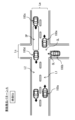
- FIGs. 8, 9, and 10 show hypothetical examples of traffic conditions.
- vehicle (own vehicle) 100a is traveling on a road with one lane on each side.
- This road with one lane on each side is composed of a driving lane L1 in which vehicle 100a is traveling, and an oncoming lane L2 that is provided along the driving lane L1 via a center line.
- An intersection CL is provided in front of vehicle 100a on this road with one lane on each side.
- This road with one lane on each side is a priority road Lm in relation to the road that intersects with this road with one lane on each side at the intersection CL.
- vehicle 100a is traveling on the priority road Lm.
- the road that intersects with the priority road Lm at the intersection CL is a non-priority road Ls in relation to the priority road Lm.
- vehicle (target vehicle) 100b is stopped at a stop line SL (waiting point) (Fig. 8, time ta). There are no traffic lights at intersection CL.
- vehicle 100a recognizes that vehicle 100a is traveling on the priority road Lm. Therefore, vehicle 100a is about to enter intersection CL without decelerating.
- vehicle 100b is stopped at the stop line SL (waiting point) on the non-priority road Ls.
- the driver of vehicle 100b intends to pass (cross) the intersection CL or turn left (merge into the oncoming lane L2) at the intersection CL.
- vehicle 100b is stopped at the stop line SL (waiting point) on the non-priority road Ls
- the driver of vehicle 100b is searching for the timing to pass through the intersection CL or turn left at the intersection CL.
- the driver of vehicle 100b finds a wide space SP between vehicles 100c and 100d in the lane proceeding to the left (oncoming lane L2) on the priority road Ls.
- the driver of vehicle 100b decides to use this space SP to pass through intersection CL or to turn left at intersection CL, and starts to enter vehicle 100b into intersection CL ( Figure 9, time tb).
- the driver of vehicle 100b is distracted by using the found space SP to pass through intersection CL or to turn left at intersection CL, and inadvertently overlooks the presence of vehicle 100a.
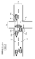
- vehicle (own vehicle) 100a is traveling on a road with one lane on each side.
- This road with one lane on each side is composed of a driving lane L1 in which vehicle 100a is traveling, and an oncoming lane L2 that is provided along driving lane L1 via a center line.
- An intersection CL is provided in front of vehicle 100a on this road with one lane on each side.
- This road with one lane on each side is a priority road Lm in relation to the road that intersects with this road with one lane on each side at intersection CL.
- vehicle 100a is traveling on the priority road Lm.
- the road that intersects with priority road Lm at intersection CL is a non-priority road Ls in relation to priority road Lm.
- the vehicle (target vehicle) 100b is traveling far ahead of the stop line SL (waiting point) ( Figure 11, time ta). There are no traffic lights at the intersection CL.
- the driver of vehicle 100a is aware that vehicle 100a is traveling on the priority road Lm. Therefore, vehicle 100a is about to enter intersection CL without slowing down. At this time, vehicle 100b is traveling much further ahead than the stop line SL (waiting point) on the non-priority road Ls. The driver of vehicle 100b intends to pass through intersection CL a short distance ahead or to turn left at intersection CL. While driving vehicle 100b on the non-priority road Ls, the driver of vehicle 100b is searching for the right timing to pass through intersection CL or to turn left at intersection CL. At this time, the driver of vehicle 100b finds space SP in the lane (oncoming lane L2) proceeding to the left on the priority road Ls.
- the driver of vehicle 100b decides to use this space SP to pass through intersection CL or to turn left at intersection CL, and starts to enter vehicle 100b into intersection CL without stopping at stop line SL ( FIG. 12 , time tb). At this time, the driver of vehicle 100b is distracted by using the found space SP to pass through intersection CL or to turn left at intersection CL, and inadvertently overlooks the presence of vehicle 100a.
- the inventors of the present application therefore came up with the idea of predicting the behavior of vehicle 100b using parameters that have a high correlation with the psychological state of the driver of vehicle 100b, such as the waiting time and margin time of vehicle 100b, as a measure to reduce the risk of collision between vehicle 100a and vehicle 100b under specific traffic conditions in which vehicle 100a and vehicle 100b are about to enter intersection CL where priority road Lm and non-priority road Ls intersect.
- the driving control system for achieving this will be described in detail below.
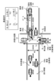
- Fig. 1 shows a schematic configuration example of a cruise control system 1 according to an embodiment of the present disclosure.
- the cruise control system 1 includes cruise control devices 10 mounted on a plurality of vehicles, and a control device 200 provided in a network environment NW to which the plurality of cruise control devices 10 are connected via wireless communication.
- the cruise control device 10 corresponds to a specific example of a "driving assistance device" according to an embodiment of the present disclosure.
- the control device 200 sequentially integrates and updates the road map information transmitted from the driving control device 10 of each vehicle, and transmits the updated road map information to each vehicle.
- the control device 200 has, for example, a road map information integration_ECU 201 and a transceiver 202.
- the road map boundary information integration ECU 201 integrates road map information collected from multiple vehicles via the transceiver 202, and sequentially updates the road map information surrounding the vehicle on the road.
- the road map information is, for example, a dynamic map, and has static information and quasi-static information that mainly constitute road information, and quasi-dynamic information and dynamic information that mainly constitute traffic information.
- the static information that makes up road information is composed of information that requires updates within one month, such as roads, structures on roads, structures around roads, lane information, road surface information, and permanent regulation information.
- roads include, for example, road locations and shapes, intersections, and road attributes (for example, national roads, prefectural roads, city roads, private roads, priority roads, non-priority roads, general roads, and expressways).
- Structures on roads include, for example, traffic signs, traffic lights, convex mirrors, and pedestrian bridges.
- Structures around roads include, for example, various buildings and parks.
- the semi-static information that makes up road information is made up of information that needs to be updated within one hour, such as traffic regulation information due to road construction or events, wide-area weather information, and traffic congestion forecasts.
- the semi-dynamic information that makes up traffic information is made up of information that requires updates within one minute, such as the actual traffic congestion situation at the time of observation, driving restrictions, temporary driving impediments such as fallen objects and obstacles, actual accident conditions, and narrow-area weather information.
- the dynamic information that constitutes the traffic information is composed of information that requires updating every second, such as information sent and exchanged between moving objects, information on currently displayed traffic signals, information on pedestrians and bicycles at intersections, and information on vehicles traveling on roads.
- Such road map information is maintained and updated periodically until the next information is received from each vehicle, and the updated road map information is appropriately transmitted to each vehicle via the transceiver 202.
- the driving control device 10 has a driving environment recognition unit 11 and a locator unit 12 as units for recognizing the driving environment around the vehicle.
- the driving control device 10 also has a driving control unit (hereinafter referred to as the "driving_ECU") 21, an engine control unit (hereinafter referred to as the “E/G_ECU”) 22, a power steering control unit (hereinafter referred to as the "PS_ECU”) 23, and a brake control unit (hereinafter referred to as the "BK_ECU”) 24.
- driving_ECU driving control unit
- E/G_ECU engine control unit
- PS_ECU power steering control unit
- BK_ECU brake control unit
- the travel_ECU 21 controls the vehicle according to, for example, the driving mode.
- the driving modes include a manual driving mode and a driving control mode.
- the manual driving mode is a driving mode that requires the driver to maintain the steering wheel, and is a driving mode in which the vehicle is driven according to the driver's driving operations, such as steering, accelerator, and brake operations.
- the driving control mode is a driving mode that supports the driver in driving operations by the driver to increase the safety of pedestrians and other vehicles around the vehicle (the vehicle itself).
- the driving_ECU 21 predicts the behavior of a traveling or stopped vehicle (hereinafter referred to as a "target vehicle") on a road that intersects at the intersection, and when the prediction results in a high possibility that the target vehicle will enter the intersection, it is possible to, for example, alert or warn the driver, and even perform risk avoidance control such as braking.
- a traveling or stopped vehicle hereinafter referred to as a "target vehicle”
- a throttle actuator 25 is connected to the output side of the E/G_ECU 22. This throttle actuator 25 opens and closes the throttle valve of an electronically controlled throttle provided in the throttle body of the engine.
- the E/G_ECU 22 controls the operation of the throttle actuator 25 by outputting a drive signal to the throttle actuator 25.
- the throttle actuator 25 opens and closes the throttle valve based on the drive signal from the E/G_ECU 22 to adjust the intake air flow rate, thereby generating the desired engine output.
- An electric power steering motor 26 is connected to the output side of the PS_ECU 23. This electric power steering motor 26 applies steering torque to the steering mechanism by the rotational force of the motor.
- the PS_ECU 23 controls the operation of the electric power steering motor 26 by outputting a drive signal to the electric power steering motor 26.
- the electric power steering motor 26 performs lane keeping control, which keeps the vehicle traveling in the current lane, and lane change control, which moves the vehicle to an adjacent lane (lane change control for overtaking control, etc.), based on the drive signal from the PS_ECU 23.
- a brake actuator 27 is connected to the output side of the BK_ECU 24. This brake actuator 27 adjusts the brake hydraulic pressure supplied to the brake wheel cylinders provided on each wheel.
- the BK_ECU 24 controls the operation of the brake actuator 27 by outputting a drive signal to the brake actuator 27. Based on the drive signal from the BK_ECU 24, the brake actuator 27 generates a braking force on each wheel using the brake wheel cylinders, forcibly slowing down the wheels.
- the driving environment recognition unit 11 is fixed, for example, to the center of the upper part of the interior front of the vehicle.
- This driving environment recognition unit 11 has an on-board camera (stereo camera) consisting of a main camera 11a and a sub-camera 11b, an image processing unit (IPU) 11c, and a driving environment detection unit 11d.
- stereo camera stereo camera
- IPU image processing unit
- the main camera 11a and the sub-camera 11b are autonomous sensors that sense the real space around the vehicle.
- the main camera 11a and the sub-camera 11b are, for example, arranged at symmetrical positions on either side of the central part in the width direction of the vehicle, making it possible to capture stereo images of the area in front of the vehicle from different viewpoints.
- the IPU 11c is capable of generating a distance image calculated from the amount of deviation in the positions of corresponding objects based on a pair of stereo images of the area in front of the vehicle captured by the main camera 11a and the sub-camera 11b.
- the driving environment detection unit 11d can, for example, determine the lane markings that divide the road around the vehicle based on the distance image received from the IPU 11c.
- the driving environment detection unit 11d can also, for example, determine the road curvature [1/m] of the markings that divide the left and right sides of the road (driving lane) on which the vehicle is traveling, and the width between the left and right markings (vehicle width).
- the driving environment detection unit 11d can also, for example, perform a predetermined pattern matching on the distance image to detect lanes and three-dimensional objects such as structures that exist around the vehicle.
- the driving environment detection unit 11d when detecting a three-dimensional object in the driving environment detection unit 11d, for example, the type of the three-dimensional object, the distance to the three-dimensional object, the speed of the three-dimensional object, and the relative speed between the three-dimensional object and the vehicle (host vehicle) are detected.
- three-dimensional objects to be detected include traffic lights, intersections, road signs, stop lines, other vehicles, pedestrians, and various buildings.
- the driving environment detection unit 11d is capable of outputting information about the detected three-dimensional objects to the driving_ECU 21, for example.
- the locator unit 12 estimates the position of the vehicle (own vehicle position) on a road map, and has a locator calculation unit 13 that estimates the own vehicle position. Sensors required for estimating the vehicle position (own vehicle position) are connected to the input side of this locator calculation unit 13. Such sensors include, for example, an acceleration sensor 14, a vehicle speed sensor 15, a gyro sensor 16, and a GNSS receiver 17.
- the acceleration sensor 14 is capable of detecting the longitudinal acceleration of the vehicle.
- the vehicle speed sensor 15 is capable of detecting the speed of the vehicle.
- the gyro sensor 16 is capable of detecting the angular velocity or angular acceleration of the vehicle.
- the GNSS receiver 17 is capable of receiving positioning signals transmitted from a plurality of positioning satellites.
- a transceiver 18 is connected to the locator calculation unit 13 for transmitting and receiving information to and from the control device 200, as well as transmitting and receiving information to and from other vehicles.
- a high-precision road map database 19 is connected to the locator calculation unit 13.
- the high-precision road map database 19 is a large-capacity storage medium such as an HDD, and stores high-precision road map information (dynamic map).
- This high-precision road map information like the road map information contained in the road map information integration_ECU 201, has static information and quasi-static information that mainly constitute road information, and quasi-dynamic information and dynamic information that mainly constitute traffic information.
- the locator calculation unit 13 includes, for example, a map information acquisition unit 13a, a vehicle position estimation unit 13b, and a driving environment recognition unit 13c.
- the vehicle position estimation unit 13b is capable of acquiring the position coordinates of the vehicle (own vehicle) based on the positioning signal received by the GNSS receiver 17.
- the vehicle position estimation unit 13b is also capable of estimating the vehicle's position on the road map by map matching the acquired position coordinates on the route map information.
- the map information acquisition unit 13a is capable of acquiring map information of a predetermined range including the vehicle (own vehicle) from map information stored in the high-precision road map database 19, based on the position coordinates of the vehicle (own vehicle) acquired by the vehicle position estimation unit 13b.
- the vehicle position estimation unit 13b can estimate the vehicle's position on a road map by switching to autonomous navigation, which estimates the vehicle's position based on the vehicle speed detected by the vehicle speed sensor 15, the angular velocity detected by the gyro sensor 16, and the longitudinal acceleration detected by the acceleration sensor 14.
- the vehicle position estimation unit 13b estimates the position of the vehicle (host vehicle position) on a road map based on the positioning signal received by the GNSS receiver 17 or information detected by the gyro sensor 16, etc., and is then able to determine the road type, etc. of the road on which the vehicle (host vehicle) is traveling based on the estimated host vehicle position on the road map.
- the driving environment recognition unit 13c is capable of updating the road map information stored in the high-precision road map database 19 to the latest state using road map information acquired by external communication (roadside-to-vehicle communication and vehicle-to-vehicle communication) via the transceiver 18.
- This information update is performed not only for static information, but also for quasi-static information, quasi-dynamic information, and dynamic information.
- the road map information is composed of road information and traffic information acquired by communication outside the vehicle, and information on moving bodies such as vehicles traveling on roads is updated in approximately real time.
- the driving environment recognition unit 13c verifies road map information based on the driving environment information recognized by the driving environment recognition unit 11, and is capable of updating the road map information stored in the high-precision road map database 19 to the latest state.
- This information update is performed not only for static information, but also for quasi-static information, quasi-dynamic information, and dynamic information. As a result, information on moving objects such as vehicles traveling on roads recognized by the driving environment recognition unit 11 is updated in real time.
- the road map information thus updated is then transmitted to the control device 200 and vehicles surrounding the vehicle (the vehicle itself) by road-to-vehicle communication and vehicle-to-vehicle communication via the transceiver 18. Furthermore, the driving environment recognition unit 13c is capable of outputting, from the updated road map information, map information of a predetermined range including the vehicle's position estimated by the vehicle position estimation unit 13b, together with the vehicle's position (vehicle position information) to the driving_ECU 21.
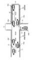
- FIGS. 2 and 3 show an example of a driving assistance procedure in the cruise control system 1.
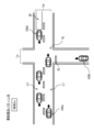
- FIG. 4 shows an example of a traffic situation in steps S101 to S108 in FIG. 2.
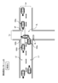
- FIG. 5 shows an example of two areas (nearby area Ra, evaluation target area Rb) defined for calculating the passing probability P in steps S109 to S111 in FIG. 3.
- FIG. 4 shows an example of the conditions (passing conditions) for the vehicle 100b (target vehicle) to pass through the space SP.
- the passing probability P refers to the possibility that the vehicle 100b will enter the space SP.
- vehicle (host vehicle) 100a is traveling on a road with one lane in each direction.
- Vehicle 100a corresponds to a specific example of a "first vehicle” according to an embodiment of the present disclosure.
- This road with one lane in each direction is composed of a driving lane L1 in which vehicle 100a is traveling, and an oncoming lane L2 that is provided along driving lane L1 with a center line interposed therebetween.
- An intersection CL is provided ahead of vehicle 100a on this road with one lane in each direction.
- This road with one lane in each direction is a priority road Lm in relation to the road that intersects with this road with one lane in each direction at the intersection CL. In other words, vehicle 100a is traveling on the priority road Lm.
- the road that intersects with the priority road Lm at the intersection CL is a non-priority road Ls in relation to the priority road Lm.
- a vehicle (target vehicle) 100b is stopped at a stop line SL (waiting point) or traveling toward the intersection CL.
- Vehicle 100b corresponds to a specific example of a "second vehicle" according to an embodiment of the present disclosure.
- vehicle 100a recognizes that vehicle 100a is traveling on the priority road Lm. Therefore, vehicle 100a is about to enter intersection CL without decelerating.
- vehicle 100b is stopped at the stop line SL (waiting point) on the non-priority road Ls or traveling toward intersection CL.
- the driver of vehicle 100b intends to pass through intersection CL or turn left at intersection CL.
- vehicle 100b is stopped at the stop line SL (waiting point) on the non-priority road Ls or traveling toward intersection CL, the driver of vehicle 100b is searching for the timing to pass through intersection CL or turn left at intersection CL.
- the driver of vehicle 100b finds a wide space SP between vehicles 100c and 100d in the lane proceeding to the left (oncoming lane L2) on the priority road Ls.
- the driver of vehicle 100b decides to use this space SP to pass through intersection CL or to turn left at intersection CL, and enters vehicle 100b into intersection CL.
- the driver of vehicle 100b is distracted by using the space SP he found to pass through intersection CL or to turn left at intersection CL, and inadvertently overlooks the presence of vehicle 100a.
- the travel_ECU 21 is therefore capable of performing calculations that take such events into consideration. Specifically, the travel_ECU 21 is capable of determining whether or not a specific traffic situation is occurring in which the vehicles 100a and 100b are attempting to enter an intersection CL where the priority road Lm and the non-priority road Ls intersect. After determining that a specific traffic situation is occurring, the travel_ECU 21 performs calculations regarding the existence of a space SP (entry space) into which the vehicle 100b can enter, and the waiting time Tw or margin time Ts of the vehicle 100b, and is capable of predicting the possibility (passing probability P) that the vehicle 100b will enter the space SP based on the results of the calculations.
- a space SP entity space
- Tw or margin time Ts of the vehicle 100b is capable of predicting the possibility (passing probability P) that the vehicle 100b will enter the space SP based on the results of the calculations.
- the space SP refers to a space formed by two vehicles adjacent to each other in a common lane (for example, the oncoming lane L2).
- the "space SP (entry space) into which the vehicle 100b can enter” refers to a space having a width (length) into which the vehicle 100b can theoretically enter when the vehicle 100b is stopped at the stop line SL or traveling toward the intersection CL.
- the "entry space” must exist at least within a range that can be recognized by the driver of the vehicle 100b. Therefore, the "entry space” must exist within an area with a radius of about 50 m centered on the vehicle 100b, for example.
- the travel_ECU 21 is capable of determining whether or not a space SP that satisfies the following passing conditions (1) and (2) exists among one or more spaces SP formed by two adjacent vehicles in the oncoming lane L2 of the priority road Ls.
- the passing conditions (1) and (2) are expressed as equations as shown in the following paragraph.
- the travel_ECU 21 is capable of determining that space SP as a space SP into which the vehicle 100b can enter (entry space).
- Vehicle 100b does not come into contact with vehicle 100d, and after vehicle 100d passes through intersection CL, vehicle 100b passes through space SP or merges into space SP.
- Vehicle 100b passes through the intersection CL without coming into contact with vehicle 100c, or after vehicle 100b passes through the space SP or merges into the space SP, vehicle 100c passes through intersection CL.
- Vx1 Vehicle speed [m/s]
- Vx2 Vehicle 100d speed [m/s]
- Vy Velocity of vehicle 100b [m/s]
- Lx1 Distance [m] between the rear end of the space SP and the point (intersection point ⁇ ) where the vehicles 100c and 100b intersect within the intersection CL.
- Lx2 Distance [m] between the front end of the space SP and the point (intersection point ⁇ ) where the vehicles 100c and 100b intersect within the intersection CL.
- Ly The sum of the width [m] of the priority road Lm at the intersection CL and the total length [m] of the vehicle 100b [m]
- Wr Width of priority road Lm [m]
- Wb 1/2 the width of the non-priority road Ls [m]
- Wd 1/2 the width of the priority road Lm [m]
- Ls1 Distance from the stop line SL to the priority road Lm within the intersection SL [m] (Wr/2+Ls1)/Vy: time [s] required for the vehicle 100b to travel from the stop line SL to the oncoming lane L2 in the intersection CL (Lx2+Wb/2)/Vx2: time [s] required for the vehicle 100d to pass through the intersection CL from its current position Ly/Vy: time [s] required for the vehicle 100b to move from the position of the stop line SL to the position where it passes through the intersection CL (the position of the vehicle indicated by the dashed line in FIG. 4) (Lx1-Wb/2)/Vx1
- Examples of traffic situations in which it can be said that "there is no entry space” include the traffic situations shown below.
- the driving_ECU 21 can estimate whether the traffic conditions ahead of the vehicle 100a are as described above, for example, from data obtained from a sensor of the vehicle 100a (e.g., the driving environment recognition unit 11), data obtained from a road surface sensor through road-to-vehicle communication by the receiver-transmitter 18, or data obtained from another vehicle through vehicle-to-vehicle communication by the receiver-transmitter 18. If these data include, for example, data indicating that multiple vehicles are traveling without interruption in the oncoming lane L2, the driving_ECU 21 can determine that the traffic conditions ahead of the vehicle 100a are as described above.
- the waiting time Tw refers to the time that the vehicle 100b is stopped at the stop line SL. This time refers to the time (predicted time) that the vehicle 100b stopped at the stop line SL is predicted to spend from the time when the vehicle 100b stops at the stop line SL until it departs from the stop line SL, or the actual time that has a predetermined correlation with the predicted time.
- the start timing of the predicted time and the actual measurement time may include various timings, for example, as shown below.
- the start timing of the predicted time and the actual measurement time may be, for example, the timing when the vehicle 100b stops at the stop line SL, or the timing when measurement of the predicted time and the actual measurement time starts while the vehicle 100b is stopped at the stop line SL.
- the start timing of the predicted time and the actual measurement time may be, for example, the timing when an "entry space" is detected while the vehicle 100b is stopped at the stop line SL.
- the start timing of the predicted time and the actual measurement time may be, for example, the timing when the vehicle 100b is detected to be stopped at the stop line SL, or the timing when the vehicle 100b stopped at the stop line SL is detected.
- the timing at which the actual measurement time ends may be, for example, the timing at which the travel_ECU 21 starts calculating the waiting time Tw (the timing at which step S110 described below starts).
- the timing at which the travel_ECU 21 starts calculating the waiting time Tw is a predetermined period of time before the vehicle 100b actually departs from the stop line SL.
- the timing at which the actual measurement time ends is not limited to the timing at which step S110 described below starts.
- the driving_ECU 21 is capable of calculating the waiting time Tw (predicted time or actual measured time) based on, for example, data obtained from a sensor (e.g., the driving environment recognition unit 11) of the vehicle 100a, data obtained from a road surface sensor through road-to-vehicle communication by the receiver-transmitter 18, or data obtained from another vehicle through vehicle-to-vehicle communication by the receiver-transmitter 18.
- a sensor e.g., the driving environment recognition unit 11
- the margin time Ts refers to a margin time when the vehicle 100b enters the "entry space".
- the margin time Ts is, for example, the difference between the time when the vehicle 100b is predicted to reach the "entry space” and the current time.
- the margin time Ts may be, for example, a time that has a predetermined correlation with the difference between the time when the vehicle 100b is predicted to reach the "entry space” and the current time.
- the margin time Ts may be, for example, a time that has a predetermined correlation with the difference between the time when the vehicle 100b is predicted to reach the stop line SL and the current time.
- the driving_ECU 21 is capable of calculating the waiting time Tw (predicted time or actual measured time) based on, for example, data obtained from a sensor (e.g., the driving environment recognition unit 11) of the vehicle 100a, data obtained from a road surface sensor through road-to-vehicle communication by the receiver-transmitter 18, or data obtained from another vehicle through vehicle-to-vehicle communication by the receiver-transmitter 18.
- a sensor e.g., the driving environment recognition unit 11
- the passing probability P refers to the possibility that the vehicle 100b will enter the space SP.
- the passing probability P can be derived, for example, by the following formula (1) or formula (2).
- Formula (1) is a formula for deriving the passing probability P when the vehicle 100b is stopped at the stop line SL.
- Formula (2) is a formula for deriving the passing probability P when the vehicle 100b is traveling on the non-priority road Ls.
- N1 number of vehicles in the neighborhood area Ra (number of partial recognition loads)
- N2 Number of vehicles in the evaluation target area Rb (total recognized load number)
- Figure 5 shows an example of a counting area for the number of vehicles near intersection CL.
- Figure 5 shows examples of a nearby area Ra and an evaluation area Rb as counting areas.
- Nearby area Ra is an area on priority road Lm near space SP (entry space) into which vehicle 100b can enter.
- nearby area Ra includes two vehicles (e.g., vehicles 100c, 100d) that make up the entry space, and a vehicle (e.g., vehicle 100e) traveling in the area between the entry space and vehicle 100b in the lane (traveling lane L1) between the entry space and vehicle 100b. Therefore, the number of vehicles N1 is three in Figure 5.
- Evaluation area Rb is an area in front of vehicle 100a on priority road Lm, and includes vehicle 100a and nearby area Ra.
- the evaluation target area Rb includes vehicles 100c, 100d, vehicle 100e, vehicle 100a, and vehicle 100f traveling beside vehicle 100a. Therefore, the number of vehicles N2 in FIG. 5 is 5.
- the driving_ECU 21 is capable of calculating the passing probability P based on, for example, data obtained from a sensor (e.g., the driving environment recognition unit 11) of the vehicle 100a, data obtained from a road surface sensor through road-to-vehicle communication by the receiver-transmitter 18, or data obtained from another vehicle through vehicle-to-vehicle communication by the receiver-transmitter 18.
- the timing for calculating the number of vehicles N1 and the number of vehicles N2 is, for example, the timing when it is determined that there is a space SP (entry space) into which the vehicle 100b can enter, that is, the timing when step S108 described below is executed.
- a driving assistance procedure in the driving control system 1 will be described with reference to Figures 2 and 3.
- a stereo camera provided on the vehicle 100a captures an image of the area ahead of the vehicle 100a, and outputs the resulting stereo image to the IPU 11c.
- the IPU 11c generates a distance image based on the stereo image captured by the stereo camera, and outputs the image to the driving environment detection unit 11d.
- the driving environment detection unit 11d performs a predetermined pattern matching or the like on the distance image generated by the IPU 11c, and detects the priority road Lm, the driving lane L1, the oncoming lane L2, the non-priority road Ls, the intersection CL, vehicles on the priority road Lm (e.g., vehicles 100a, 100c to 100f), and vehicles on the non-priority road Ls (e.g., vehicle 100b).
- the driving environment recognition unit 13c uses the road map information acquired from external communication to detect the priority road Lm, the driving lane L1, the oncoming lane L2, the non-priority road Ls, the intersection CL, vehicles on the priority road Lm (e.g., vehicles 100a, 100c to 100f), and vehicles on the non-priority road Ls (e.g., vehicle 100b).
- the road map information acquired from external communication includes information on vehicles on the priority road Lm (e.g., vehicles 100a, 100c to 100f) and vehicles on the non-priority road Ls (e.g., vehicle 100b).
- the driving environment recognition unit 13c can detect vehicles on the priority road Lm (e.g., vehicles 100a, 100c to 100f) and vehicles on the non-priority road Ls (e.g., vehicle 100b) using the road map information acquired from external communication.
- the priority road Lm e.g., vehicles 100a, 100c to 100f
- the non-priority road Ls e.g., vehicle 100b
- the vehicle position estimation unit 13b acquires the position coordinates of the vehicle 100a based on the positioning signal received by the GNSS receiver 17. The vehicle position estimation unit 13b further acquires the vehicle speed (the speed of the vehicle 100a) detected by the vehicle speed sensor 15.
- the driving_ECU 21 acquires road information Da and vehicle information Db based on various information obtained from the driving environment detection unit 11d, the vehicle position estimation unit 13b, and the driving environment recognition unit 13c (step S101).
- the road information Da includes information on the priority road Lm, the driving lane L1, the oncoming lane L2, the non-priority road Ls, and the intersection CL detected by the driving environment detection unit 11d or the driving environment recognition unit 13c.
- the vehicle information Db includes information on the speed (vehicle speed) of the vehicle 100a acquired from the vehicle position estimation unit 13b, and information on vehicles on the priority road Lm (e.g., vehicles 100a, 100c to 100f) and vehicles on the non-priority road Ls (e.g., vehicle 100b) acquired from the driving environment detection unit 11d or the driving environment recognition unit 13c.
- vehicles on the priority road Lm e.g., vehicles 100a, 100c to 100f
- vehicles on the non-priority road Ls e.g., vehicle 100b
- the driving_ECU 21 determines whether an intersection CL exists ahead of the vehicle 100a (step S102). If the road information Da includes information on the intersection CL (step S102; Y), the driving_ECU 21 determines whether the lane on which the vehicle 100a is traveling (driving lane L1) is a priority road Lm (step S103). If the road information Da includes information on the priority road Lm (step S103; Y), the driving_ECU 21 determines whether a vehicle (target vehicle) 100b traveling on a non-priority road Ls exists (step S104).
- the driving_ECU 21 calculates the inter-vehicle space ⁇ L formed by multiple vehicles traveling on the oncoming lane L2 of the priority road Lm (step S105). If the calculated inter-vehicle space ⁇ L is equal to or greater than a predetermined threshold ⁇ Lth (step S106; Y), the travel_ECU 21 recognizes the space having an inter-vehicle space ⁇ L equal to or greater than the threshold ⁇ Lth as the above-mentioned space SP.
- the travel_ECU 21 then calculates the passing conditions for the space SP (step S107). If the space SP satisfies the passing conditions (step S108; Y), it calculates the number of vehicles N1, N2, the waiting time Tw or margin time Ts, and the passing probability P (steps S109, S110, S111).
- the traveling_ECU 21 executes step S101 if any of the following conditions is met in each of the above steps.
- step S102; N When the road information Da does not include information on the intersection CL (step S102; N)
- step S103; N When the road information Da does not include information on the priority road Lm
- step S104; N When the vehicle information Db does not include information on the vehicle 100b (step S104; N)
- step S106; N When the vehicle space ⁇ L is less than the threshold value ⁇ Lth (step S106; N)
- the space SP does not satisfy the passing condition
- the traveling_ECU 21 executes driving assistance according to the passing probability P (step S112).
- the traveling_ECU 21 does not execute any driving assistance.
- the driving_ECU 21 alerts the driver of the vehicle 100a.
- the driving_ECU 21 outputs a video signal to a head-up display that displays an image on the windshield, in which a shape image with a color (e.g., yellow) indicating the presence of the vehicle 100b on the non-priority road Ls is superimposed.
- a shape image with a color e.g., yellow
- the driving_ECU 21 issues a warning to the driver of the vehicle 100a.
- the driving_ECU 21 outputs a video signal to a head-up display that displays an image on the front window, in which a form image with a color (e.g., red) that indicates the presence of the vehicle 100b on the non-priority road Ls is superimposed.
- the driving_ECU 21 outputs an audio signal that produces an intermittent sound to the speaker.
- the travel_ECU 21 performs risk avoidance control such as braking on the vehicle 100a.
- the travel_ECU 21 performs a predetermined risk avoidance braking when there is 3 seconds or less until a collision between the vehicles 100a and 100b. This makes it possible to avoid a collision between the vehicles 100a and 100b.
- data is acquired indicating that vehicle 100b exists, that a plurality of vehicles exist in at least one lane (traveling lane L1, oncoming lane L2) ahead of vehicle 100a, and that a space SP (entry space) into which vehicle 100b can enter exists in one or more spaces formed by two vehicles adjacent to each other in a common lane (oncoming lane L2). Then, when vehicle 100b is waiting at stop line SL, the waiting time Tw of vehicle 100b is estimated based on the acquired data. When vehicle 100b is traveling toward stop line SL, the margin time Ts when vehicle 100b enters the entry space is estimated based on the acquired data.
- the possibility (passing probability P) of vehicle 100b entering the entry space is predicted based on the waiting time Tw or margin time Ts. This makes it possible to predict the possibility that vehicle 100b will pass through intersection CL due to the psychological influence of the driver of vehicle 100b. As a result, it is possible to issue warnings, perform braking control, and perform other actions that can avoid a collision between vehicles 100a and 100b.
- the possibility (passing probability P) of vehicle 100b entering the entry space is predicted based on the number of vehicles N1, N2, the waiting time Tw, or the margin time Ts. This makes it possible to predict the possibility that vehicle 100b will pass through intersection CL due to the psychological influence of the driver of vehicle 100b. As a result, it is possible to perform attention calls, warnings, braking control, etc. that can avoid a collision between vehicles 100a and 100b.
- the possibility (passage probability P) that vehicle 100b will enter the entry space can be predicted even when vehicle 100a has difficulty communicating with the network environment NW.
- the possibility (passing probability P) of vehicle 100b entering the entry space can be predicted more accurately than when road information Da and vehicle information Db are generated only by sensors installed on vehicle 100a.
- the evaluation target area Rb may be, for example, an area including the vicinity area Ra and the area from the position of the vehicle 100a to the entry space in the lane (traveling lane L1) on which the vehicle 100a is traveling, as shown in Fig. 6.
- the number of vehicles traveling in an area that is relatively less affected by the entry of the vehicle 100b into the entry space can be excluded from the number of vehicles N2.
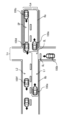
- the traveling_ECU 21 may be capable of predicting the possibility (passing probability P) of the vehicle 100b entering the entry space based on the congestion degree Cd of the nearby area Ra and the evaluation target area Rb, instead of the waiting time Tw and the margin time Ts, for example, as shown in step S113 of Figure 7.
- the present disclosure is applied to driving assistance at an intersection CL where a priority road Lm and a non-priority road Ls intersect.
- the present disclosure may be applied to driving assistance at a junction where a non-priority road Ls merges with a priority road Lm. In such a case, it is possible to predict the possibility that the vehicle 100b will merge due to the psychological influence of the driver of the vehicle 100b, as in the above embodiment and its modified example.
- the travel_ECU 21 may acquire road information Da and vehicle information Db based on various data of the sensor detection area SR obtained from various sensors mounted on the vehicle 100a.
- the road information Da includes information on the priority road Lm, the driving lane L1, the oncoming lane L2, the non-priority road Ls, and the intersection CL detected by the driving environment recognition unit 13c.
- the vehicle information Db includes information on the speed (vehicle speed) of the vehicle 100a acquired from the vehicle position estimation unit 13b, and information on vehicles on the priority road Lm (e.g., vehicles 100a, 100c to 100f) and vehicles on the non-priority road Ls (e.g., vehicle 100b). Even in this case, it is possible to predict the possibility that the vehicle 100b will merge or cross due to the psychological influence of the driver of the vehicle 100b.
- the present disclosure can have the following configuration.
- the control unit is acquiring first data indicating that the prediction target vehicle exists, that a plurality of second vehicles exist in at least one lane ahead of the first vehicle, and that an entry space into which the prediction target vehicle can enter exists in one or more spaces formed by two of the second vehicles adjacent to each other in a common lane;
- the prediction target vehicle is waiting at the waiting point, estimating a waiting time of the prediction target vehicle at the waiting point based on the acquired first data, and when the prediction target vehicle is traveling toward the waiting point, estimating a margin time when the prediction target vehicle enters the entry space based on the acquired first data; and
- the control unit is capable of estimating, based on the acquired first data, a time required for the prediction target vehicle to enter the entry space, or a time having a predetermined correlation with that time, as the margin time.
- the control unit is obtaining second data indicating that the entry space does not exist; and and estimating the waiting time based on the first data and the second data.
- the control unit is estimating the number of vehicles within a predetermined area ahead of the first vehicle based on the acquired first data; and predicting the possibility that the predicted vehicle will enter the entry space based on the number of vehicles and the waiting time or the margin time.
- the control unit estimates, based on the acquired first data, a number N1 of vehicles in the vicinity of the entry space on the priority road, and a number N2 of vehicles in an evaluation target area of the priority road extending from the position of the first vehicle to the vicinity of the entry space;
- the driving assistance device described in (4) is capable of predicting the possibility that the prediction target vehicle will enter the entry space based on the number of vehicles N1, the number of vehicles N2, and the waiting time or the margin time.
- the control unit is Based on the acquired first data, a number N1 of vehicles in the vicinity of the entry space on the priority road and a number N3 of vehicles in an evaluation target area extending from the position of the first vehicle to the vicinity of the entry space in the same lane as the first vehicle are estimated;
- the driving assistance device described in (4) is capable of predicting the possibility that the predicted vehicle will enter the entry space based on the number of vehicles N1, the number of vehicles N3, and the waiting time or the margin time.
- a control unit capable of predicting the behavior of a prediction target vehicle when a non-priority road that merges with or intersects with a priority road having one or more lanes in each direction is present ahead of a first vehicle, and a prediction target vehicle is present on the non-priority road, the prediction target vehicle being parked at a waiting point or traveling toward the waiting point;
- the control unit is acquiring data indicating that the prediction target vehicle exists, that a plurality of second vehicles exist in at least one lane ahead of the first vehicle, and that an entry space into which the prediction target vehicle can enter exists in one or more spaces formed by two of the second vehicles adjacent to each other in a common lane;
- the prediction target vehicle is waiting at the waiting point, estimating a waiting time of the prediction target vehicle at the waiting point based on the acquired data, and when the prediction target vehicle is traveling toward the waiting point, estimating a margin time when the prediction target vehicle enters the entry space based on the acquired data; and predicting the possibility that the prediction target vehicle will enter the entry space
- a driving assistance method capable of predicting a behavior of a prediction target vehicle when a non-priority road that merges with or intersects with a priority road having one or more lanes in each direction is present ahead of a first vehicle, and a prediction target vehicle is present on the non-priority road that is stopped at a waiting point or traveling toward the waiting point, comprising: acquiring data indicating that the prediction target vehicle exists, that a plurality of second vehicles exist in at least one lane ahead of the first vehicle, and that an entry space into which the prediction target vehicle can enter exists in one or more spaces formed by two of the second vehicles adjacent to each other in a common lane; When the prediction target vehicle is waiting at the waiting point, estimating a waiting time of the prediction target vehicle at the waiting point based on the acquired data, and when the prediction target vehicle is traveling toward the waiting point, estimating a margin time when the prediction target vehicle enters the entry space based on the acquired data; predicting a possibility that the prediction target vehicle will enter the entry space based on the waiting time or the
- a control unit capable of predicting the behavior of a prediction target vehicle when a non-priority road that merges with or intersects with a priority road having one or more lanes in each direction is present ahead of a first vehicle, and a prediction target vehicle is present on the non-priority road, the prediction target vehicle being parked at a waiting point or traveling toward the waiting point;
- the control unit is acquiring data indicating that the prediction target vehicle exists, that a plurality of second vehicles exist in at least one lane ahead of the first vehicle, and that an entry space into which the prediction target vehicle can enter exists in one or more spaces formed by two of the second vehicles adjacent to each other in a common lane; estimating a first congestion degree in the vicinity of the entry space on the priority road and a second congestion degree in an evaluation target area of the priority road extending from the position of the first vehicle to the vicinity of the entry space based on the acquired data; and predicting a possibility that the prediction target vehicle will enter the entry space based on the first congestion degree and the second congestion degree.
- control unit capable of predicting the behavior of a prediction target vehicle when a non-priority road that merges with or intersects with a priority road having one or more lanes in each direction is present ahead of a first vehicle, and a prediction target vehicle is present on the non-priority road, the prediction target vehicle being parked at a waiting point or traveling toward the waiting point;
- the control unit is acquiring data indicating that the prediction target vehicle exists, that a plurality of second vehicles exist in at least one lane ahead of the first vehicle, and that an entry space into which the prediction target vehicle can enter exists in one or more spaces formed by two of the second vehicles adjacent to each other in a common lane; estimating a first congestion degree in the vicinity of the entry space on the priority road and a third congestion degree in an evaluation target area extending from the position of the first vehicle to the vicinity of the entry space in the same lane as the first vehicle based on the acquired data; and predicting a possibility that the prediction target vehicle will enter the entry space based on the first congestion degree and the third congestion
Landscapes
- Physics & Mathematics (AREA)
- General Physics & Mathematics (AREA)
- Engineering & Computer Science (AREA)
- Chemical & Material Sciences (AREA)
- Analytical Chemistry (AREA)
- Automation & Control Theory (AREA)
- Mathematical Physics (AREA)
- Transportation (AREA)
- Mechanical Engineering (AREA)
- Traffic Control Systems (AREA)
Abstract
Description
本開示は、車両に搭載される運転支援装置、車両および運転支援方法に関する。 This disclosure relates to a driving assistance device mounted on a vehicle, the vehicle, and a driving assistance method.
近年、自動車等の車両においては、運転者の運転操作を必要とせずに車両を自動的に走行させる自動運転制御技術の開発が進められている。また、この種の自動運転制御技術を利用して運転者の運転操作を支援するための各種の制御を行う運転支援装置についての様々な提案がなされており、また一般に実用化されつつある。このような運転支援装置に関する技術が、例えば、特許文献1~4に開示されている。 In recent years, there has been progress in the development of automatic driving control technology for automobiles and other vehicles that allows the vehicle to travel automatically without the driver's intervention. In addition, various proposals have been made for driving assistance devices that use this type of automatic driving control technology to perform various controls to assist the driver in driving operations, and these devices are becoming more widely used. Technologies related to such driving assistance devices are disclosed, for example, in Patent Documents 1 to 4.
本開示の第1の側面に係る運転支援装置は、片側1車線以上の優先道路に合流もしくは交差する非優先道路が第1の車両の前方に存在し、さらに、非優先道路において待機地点に停車中、もしくは待機地点に向かって走行中の予測対象車両が存在するときに、予測対象車両の行動を予測することの可能な制御部を備えている。制御部は、以下の(A1)、(A2)、(A3)を行うことが可能となっている。
(A1)予測対象車両が存在することと、第1の車両の前方の少なくとも1つの車線において複数の第2の車両が存在することと、共通の車線において互いに隣接する2つの第2の車両によって形成される1または複数のスペースの中に、予測対象車両が進入可能な進入スペースが存在することとを示す第1のデータを取得すること
(A2)待機地点に予測対象車両が待機している場合、取得した第1のデータに基づいて、予測対象車両の、待機地点での待ち時間を推定し、待機地点に向かって予測対象車両が走行している場合、取得した第1のデータに基づいて、予測対象車両が進入スペースへ進入する際の余裕時間を推定すること
(A3)待ち時間もしくは余裕時間に基づいて、予測対象車両が進入スペースへ進入する可能性を予測すること
A driving assistance device according to a first aspect of the present disclosure includes a control unit capable of predicting the behavior of a prediction target vehicle when a non-priority road that merges with or intersects with a priority road with one or more lanes in each direction is present ahead of a first vehicle, and a prediction target vehicle is present that is stopped at a waiting point on the non-priority road or traveling toward a waiting point. The control unit is capable of performing the following (A1), (A2), and (A3).
(A1) acquiring first data indicating that a prediction target vehicle exists, that a plurality of second vehicles exist in at least one lane ahead of a first vehicle, and that an entry space into which the prediction target vehicle can enter exists among one or more spaces formed by two second vehicles adjacent to each other in a common lane; (A2) estimating a waiting time of the prediction target vehicle at the waiting point based on the acquired first data when the prediction target vehicle is waiting at a waiting point, and estimating a margin time when the prediction target vehicle enters the entry space based on the acquired first data when the prediction target vehicle is traveling toward the waiting point; (A3) predicting the possibility that the prediction target vehicle will enter the entry space based on the waiting time or margin time.
本開示の第2の側面に係る車両は、片側1車線以上の優先道路に合流もしくは交差する非優先道路が第1の車両の前方に存在し、さらに、非優先道路において待機地点に停車中、もしくは待機地点に向かって走行中の予測対象車両が存在するときに、予測対象車両の行動を予測することの可能な制御部を備えている。制御部は、以下の(B1)、(B2)、(B3)を行うことが可能となっている。
(B1)予測対象車両が存在することと、第1の車両の前方の少なくとも1つの車線において複数の第2の車両が存在することと、共通の車線において互いに隣接する2つの第2の車両によって形成される1または複数のスペースの中に、予測対象車両が進入可能な進入スペースが存在することとを示す第1のデータを取得すること
(B2)待機地点に予測対象車両が待機している場合、取得した第1のデータに基づいて、予測対象車両の、待機地点での待ち時間を推定し、待機地点に向かって予測対象車両が走行している場合、取得した第1のデータに基づいて、予測対象車両が進入スペースへ進入する際の余裕時間を推定すること
(B3)待ち時間もしくは余裕時間に基づいて、予測対象車両が進入スペースへ進入する可能性を予測すること
A vehicle according to a second aspect of the present disclosure includes a control unit capable of predicting the behavior of a prediction target vehicle when a non-priority road that merges with or intersects with a priority road having one or more lanes in each direction is present ahead of a first vehicle, and when a prediction target vehicle is present that is stopped at a waiting point on the non-priority road or traveling toward a waiting point. The control unit is capable of performing the following (B1), (B2), and (B3).
(B1) acquiring first data indicating that a prediction target vehicle exists, that a plurality of second vehicles exist in at least one lane ahead of the first vehicle, and that an entry space into which the prediction target vehicle can enter exists among one or more spaces formed by two second vehicles adjacent to each other in a common lane; (B2) estimating a waiting time of the prediction target vehicle at the waiting point based on the acquired first data when the prediction target vehicle is waiting at a waiting point, and estimating a margin time when the prediction target vehicle enters the entry space based on the acquired first data when the prediction target vehicle is traveling toward the waiting point; (B3) predicting the possibility that the prediction target vehicle will enter the entry space based on the waiting time or margin time.
本開示の第3の側面に係る運転支援方法は、片側1車線以上の優先道路に合流もしくは交差する非優先道路が第1の車両の前方に存在し、さらに、非優先道路において待機地点に停車中、もしくは待機地点に向かって走行中の予測対象車両が存在するときに、予測対象車両の行動を予測することの可能な方法である。この方法は、以下の(C1)、(C2)、(C3)を含む。
(C1)予測対象車両が存在することと、第1の車両の前方の少なくとも1つの車線において複数の第2の車両が存在することと、共通の車線において互いに隣接する2つの第2の車両によって形成される1または複数のスペースの中に、予測対象車両が進入可能な進入スペースが存在することとを示す第1のデータを取得すること
(C2)待機地点に予測対象車両が待機している場合、取得した第1のデータに基づいて、予測対象車両の、待機地点での待ち時間を推定し、待機地点に向かって予測対象車両が走行している場合、取得した第1のデータに基づいて、予測対象車両が進入スペースへ進入する際の余裕時間を推定すること
(C3)待ち時間もしくは余裕時間に基づいて、予測対象車両が進入スペースへ進入する可能性を予測すること
A driving assistance method according to a third aspect of the present disclosure is a method capable of predicting the behavior of a prediction target vehicle when a non-priority road that merges with or intersects with a priority road with one or more lanes in each direction is present ahead of a first vehicle, and further when a prediction target vehicle is present that is stopped at a waiting point on the non-priority road or traveling toward the waiting point. This method includes the following (C1), (C2), and (C3).
(C1) acquiring first data indicating the presence of a prediction target vehicle, the presence of a plurality of second vehicles in at least one lane ahead of the first vehicle, and the presence of an entry space into which the prediction target vehicle can enter within one or more spaces formed by two second vehicles adjacent to each other in a common lane; (C2) estimating a waiting time of the prediction target vehicle at the waiting point based on the acquired first data when the prediction target vehicle is waiting at a waiting point, and estimating a margin time when the prediction target vehicle enters the entry space based on the acquired first data when the prediction target vehicle is traveling toward the waiting point; (C3) predicting the possibility of the prediction target vehicle entering the entry space based on the waiting time or margin time.
本開示の第4の側面に係る運転支援装置は、片側1車線以上の優先道路に合流もしくは交差する非優先道路が第1の車両の前方に存在し、さらに、非優先道路において待機地点に停車中、もしくは待機地点に向かって走行中の予測対象車両が存在するときに、予測対象車両の行動を予測することの可能な制御部を備えている。制御部は、以下の(D1)、(D2)、(D3)を行うことが可能となっている。
(D1)予測対象車両が存在することと、第1の車両の前方の少なくとも1つの車線において複数の第2の車両が存在することと、共通の車線において互いに隣接する2つの第2の車両によって形成される1または複数のスペースの中に、予測対象車両が進入可能な進入スペースが存在することとを示すデータを取得すること
(D2)取得したデータに基づいて、優先道路における進入スペースの近傍の第1混雑度と、優先道路のうち、第1の車両の位置から進入スペースの近傍までに渡る評価対象領域の第2混雑度とを推定すること
(D3)第1混雑度および第2混雑度に基づいて、予測対象車両が進入スペースへ進入する可能性を予測すること
A driving assistance device according to a fourth aspect of the present disclosure includes a control unit capable of predicting the behavior of a prediction target vehicle when a non-priority road that merges with or intersects with a priority road with one or more lanes in each direction is present ahead of a first vehicle, and a prediction target vehicle is present that is stopped at a waiting point on the non-priority road or traveling toward a waiting point. The control unit is capable of performing the following (D1), (D2), and (D3).
(D1) acquiring data indicating that a prediction target vehicle exists, that a plurality of second vehicles exist in at least one lane ahead of the first vehicle, and that an entry space into which the prediction target vehicle can enter exists within one or more spaces formed by two second vehicles adjacent to each other in a common lane; (D2) estimating a first congestion degree in the vicinity of the entry space on the priority road based on the acquired data, and a second congestion degree of an evaluation target area of the priority road extending from the position of the first vehicle to the vicinity of the entry space; (D3) predicting the possibility that the prediction target vehicle will enter the entry space based on the first congestion degree and the second congestion degree.
本開示の第5の側面に係る運転支援装置は、片側1車線以上の優先道路に合流もしくは交差する非優先道路が第1の車両の前方に存在し、さらに、非優先道路において待機地点に停車中、もしくは待機地点に向かって走行中の予測対象車両が存在するときに、予測対象車両の行動を予測することの可能な制御部を備えている。制御部は、以下の(E1)、(E2)、(E3)を行うことが可能となっている。
(E1)予測対象車両が存在することと、第1の車両の前方の少なくとも1つの車線において複数の第2の車両が存在することと、共通の車線において互いに隣接する2つの第2の車両によって形成される1または複数のスペースの中に、予測対象車両が進入可能な進入スペースが存在することとを示すデータを取得すること
(E2)取得したデータに基づいて、優先道路における進入スペースの近傍の第1混雑度と、第1の車両と同一の車線のうち、第1の車両の位置から前記進入スペースの近傍までに渡る評価対象領域の第3混雑度とを推定すること
(E3)第1混雑度および第3混雑度に基づいて、予測対象車両が進入スペースへ進入する可能性を予測すること
A driving assistance device according to a fifth aspect of the present disclosure includes a control unit capable of predicting the behavior of a prediction target vehicle when a non-priority road that merges with or intersects with a priority road with one or more lanes in each direction is present ahead of a first vehicle, and a prediction target vehicle is present that is stopped at a waiting point on the non-priority road or traveling toward a waiting point. The control unit is capable of performing the following (E1), (E2), and (E3).
(E1) acquiring data indicating that a prediction target vehicle exists, that a plurality of second vehicles exist in at least one lane ahead of the first vehicle, and that an entry space into which the prediction target vehicle can enter exists within one or more spaces formed by two second vehicles adjacent to each other in a common lane; (E2) estimating, based on the acquired data, a first congestion degree in the vicinity of the entry space on the priority road and a third congestion degree of an evaluation target area extending from the position of the first vehicle to the vicinity of the entry space in the same lane as the first vehicle; (E3) predicting the possibility that the prediction target vehicle will enter the entry space based on the first congestion degree and the third congestion degree.
以下、本開示の実施の形態について、図面を参照して詳細に説明する。 The following describes in detail the embodiments of the present disclosure with reference to the drawings.
<1.背景>
近年、自動車等の車両においては、運転者の運転操作を必要とせずに車両を自動的に走行させる自動運転制御技術の開発が進められている。また、この種の自動運転制御技術を利用して運転者の運転操作を支援するための各種の制御を行う運転支援装置についての様々な提案がなされており、また一般に実用化されつつある。このような運転支援装置に関する技術が、例えば、特許文献1~4に開示されている。
1. Background
In recent years, automatic driving control technology has been developed for vehicles such as automobiles, which allows the vehicle to travel automatically without the driver's operation. In addition, various driving support devices that use this type of automatic driving control technology to perform various controls to support the driver's driving operation have been proposed and are becoming generally practical. Technologies related to such driving support devices are disclosed in, for example, Patent Documents 1 to 4.
特許文献1に記載の発明では、自車両の周囲を走行する車両(周囲車両)の位置と走行パラメタ(速度など)から、周囲車両のドライバの運転意図を予測し、いずれかの周囲車両が、自車両が走行する車線に合流する可能性があるか否かを推定する技術が開示されている。特許文献2に記載の発明では、優先道路における合流後続車となる被合流車を特定し、被合流車との車間距離が合流安全車間距離以下の場合は、被合流車前後の交通状況を判断して、自車の合流判断をする技術が開示されている。
The invention described in Patent Document 1 discloses a technology that predicts the driving intentions of the drivers of the vehicles traveling around the vehicle (surrounding vehicles) from the positions and driving parameters (speed, etc.) of the surrounding vehicles, and estimates whether or not any of the surrounding vehicles are likely to merge into the lane in which the vehicle is traveling. The invention described in
特許文献3に記載の発明では、複数のセンサから収集したセンサデータに基づいて生成された移動体の動的情報に基づいて移動体の行動を予測し、予測した行動に基づいて、移動体同士の衝突の可能性のある行動の組み合わせを決定する技術が開示されている。特許文献4に記載の発明では、死角から飛び出して来る可能性のある移動体を予測し、予測した移動体の想定速度に基づいて、自車両が移動体に接触する可能性のある速度領域を演算する技術が開示されている。 The invention described in Patent Document 3 discloses a technology that predicts the behavior of a moving object based on dynamic information of the moving object generated based on sensor data collected from multiple sensors, and determines a combination of actions that may result in a collision between the moving objects based on the predicted behavior. The invention described in Patent Document 4 discloses a technology that predicts a moving object that may appear from a blind spot, and calculates a speed range in which the vehicle may come into contact with the moving object based on the assumed speed of the predicted moving object.
しかし、各特許文献1~4に記載の発明では、相手車両の車速や車間距離といったパラメータを利用して衝突の可能性があるか否かで相手車両の動きを推定しているだけであり、相手車両のドライバの心理状態と大きな相関を有するパラメータが考慮されていない。そのため、各特許文献1~4に記載の発明では、理論上は、相手車両が合流や車線変更等を行う可能性が非常に低い場合であっても、相手車両のドライバの心理的な影響によって、相手車両が合流や車線変更等を行ってしまう可能性があることを予測することができない。その結果、各特許文献1~4に記載の発明では、相手車両が合流や車線変更等を行い始めてから対処することになるので、自車両と相手車両とが衝突する事故が発生してしまう可能性が高い。 However, the inventions described in each of Patent Documents 1 to 4 only estimate the movement of the other vehicle based on whether or not there is a possibility of a collision using parameters such as the vehicle speed and distance between the other vehicle, and do not take into account parameters that have a high correlation with the psychological state of the driver of the other vehicle. Therefore, the inventions described in each of Patent Documents 1 to 4 are theoretically unable to predict that the other vehicle may merge or change lanes due to the psychological influence of the driver of the other vehicle, even if the other vehicle is very unlikely to merge or change lanes. As a result, the inventions described in Patent Documents 1 to 4 deal with the situation only after the other vehicle begins to merge or change lanes, so there is a high possibility of an accident occurring in which your vehicle collides with the other vehicle.
このように、従来の発明では、相手車両のドライバの心理的な影響によって、相手車両が合流や車線変更等を行ってしまう可能性を予測することができないという問題がある。そこで、本願発明者は、鋭意検討した結果、相手車両のドライバの心理的な影響によって、相手車両が合流や車線変更等を行ってしまう可能性を予測することの可能な技術を想起した。以下に、交通状況の仮想事例を挙げて、今回新たに想起した技術の背景について説明する。 As described above, conventional inventions have the problem of being unable to predict the possibility that the other vehicle will merge or change lanes due to the psychological influence of its driver. As a result of extensive research, the inventors of the present application have come up with a technology that makes it possible to predict the possibility that the other vehicle will merge or change lanes due to the psychological influence of its driver. Below, the background to this newly conceived technology is explained using hypothetical examples of traffic conditions.
図8、図9、図10は、交通状況の仮想事例を表したものである。図8、図9、図10では、車両(自車両)100aは、片側1車線の道路を走行しているものとする。この片側1車線の道路は、車両100aが走行している走行車線L1と、中央線を介して走行車線L1に沿って設けられた対向車線L2とにより構成されている。この片側1車線の道路には、車両100aの前方において、交差点CLが設けられている。この片側1車線の道路は、交差点CLにおいてこの片側1車線の道路と交差する道路との関係で、優先道路Lmとなっている。つまり、車両100aは、優先道路Lmを走行している。一方、交差点CLにおいて優先道路Lmと交差する道路は、優先道路Lmとの関係で非優先道路Lsとなっている。非優先道路Lsでは、車両(対象車両)100bが停止線SL(待機地点)で停車している(図8、時刻ta)。交差点CLには、信号機が設置されていない。
8, 9, and 10 show hypothetical examples of traffic conditions. In Figs. 8, 9, and 10, vehicle (own vehicle) 100a is traveling on a road with one lane on each side. This road with one lane on each side is composed of a driving lane L1 in which
車両100aのドライバは、車両100aが優先道路Lmを走行していることを認識している。そのため、車両100aは、減速せずに交差点CLに進入しようとしている。このとき、非優先道路Lsにおいて、車両100bが停止線SL(待機地点)で停車している。車両100bのドライバは、交差点CLを通過(交差・横断)するか、または、交差点CLで左折する(対向車線L2に合流する)ことを企図している。車両100bのドライバは、非優先道路Lsにおいて、車両100bが停止線SL(待機地点)で停車している最中に、交差点CLを通過するタイミング、または、交差点CLで左折するタイミングを探っている。このとき、車両100bのドライバは、優先道路Lsにおいて左側に進行する車線(対向車線L2)において、車両100cと車両100dとの間に広いスペースSPを見つける。車両100bのドライバは、このスペースSPを利用して、交差点CLを通過するか、または、交差点CLで左折することを決意し、車両100bを交差点CLへ進入させることを開始する(図9、時刻tb)。このとき、車両100bのドライバは、見つけたスペースSPを利用して、交差点CLを通過するか、または、交差点CLで左折することに気を取られ、車両100aの存在をうっかり見落としている。
The driver of
車両100bのドライバは、停止線SLでの停車時間(待ち時間)が長くなればなるほど、なかなか発車できないことに対してイライラする。その結果、車両100bのドライバは、普通であれば車両100aの存在を認識できるのに、イライラした感情に起因して、車両100aの存在をうっかり見落としてしまう。その結果、車両100bのドライバは、車両100aの存在を認識せずに車両100bを発車させてしまう。このような交通状況下では、車両100aと車両100bとが、交差点CLにおいて出会い頭の衝突事故を起こす可能性が高い(図10、時刻tc)。
The longer the driver of
図11、図12、図13は、交通状況の他の仮想事例を表したものである。図11、図12、図13では、車両(自車両)100aは、片側1車線の道路を走行しているものとする。この片側1車線の道路は、車両100aが走行している走行車線L1と、中央線を介して走行車線L1に沿って設けられた対向車線L2とにより構成されている。この片側1車線の道路には、車両100aの前方において、交差点CLが設けられている。この片側1車線の道路は、交差点CLにおいてこの片側1車線の道路と交差する道路との関係で、優先道路Lmとなっている。つまり、車両100aは、優先道路Lmを走行している。一方、交差点CLにおいて優先道路Lmと交差する道路は、優先道路Lmとの関係で非優先道路Lsとなっている。非優先道路Lsでは、車両(対象車両)100bが停止線SL(待機地点)よりもはるかに手前を走行している(図11、時刻ta)。交差点CLには、信号機が設置されていない。
11, 12, and 13 show other hypothetical examples of traffic conditions. In Figs. 11, 12, and 13, vehicle (own vehicle) 100a is traveling on a road with one lane on each side. This road with one lane on each side is composed of a driving lane L1 in which
車両100aのドライバは、車両100aが優先道路Lmを走行していることを認識している。そのため、車両100aは、減速せずに交差点CLに進入しようとしている。このとき、非優先道路Lsにおいて、車両100bが停止線SL(待機地点)よりもはるかに手前を走行している。車両100bのドライバは、少し先にある交差点CLを通過するか、または、交差点CLで左折することを企図している。車両100bのドライバは、非優先道路Lsにおいて、車両100bを走行させている最中に、交差点CLを通過するタイミング、または、交差点CLで左折するタイミングを探っている。このとき、車両100bのドライバは、優先道路Lsにおいて左側に進行する車線(対向車線L2)において、スペースSPを見つける。車両100bのドライバは、このスペースSPを利用して、交差点CLを通過するか、または、交差点CLで左折することを決意し、停止線SLで停止せず、車両100bを交差点CLへ進入させることを開始する(図12、時刻tb)。このとき、車両100bのドライバは、見つけたスペースSPを利用して、交差点CLを通過するか、または、交差点CLで左折することに気を取られ、車両100aの存在をうっかり見落としている。
The driver of
車両100bのドライバは、スペースSPを見つけた時から車両100bを交差点CLへ進入させるまでの時間(余裕時間)が短くなればなるほど、直ちに交差点CLに進入しなければいけないといった焦りを感じるようになる。特に、車両100bが減速する必要のない、あるいは、少ない減速量で交差点CLへ進入することにより、スペースSPに進入することができる場合、車両100bのドライバは、拙速な判断をしやすい。その結果、車両100bのドライバは、普通であれば車両100aの存在を認識できるのに、焦りの感情に起因して、車両100aの存在をうっかり見落としてしまう。その結果、車両100bのドライバは、車両100aの存在を認識せずに車両100bを交差点CLに進入させてしまう。このような交通状況下では、車両100aと車両100bとが、交差点CLにおいて出会い頭の衝突事故を起こす可能性が高い(図13、時刻tc)。
The shorter the time (leeway time) between finding the space SP and entering the intersection CL, the more the driver of the
そこで、本願発明者は、優先道路Lmと非優先道路Lsとが交差する交差点CLに車両100aおよび車両100bが進入しようとする特定の交通状況下での、車両100aと車両100bとの衝突リスクを低減する方策として、車両100bの待ち時間や、車両100bの余裕時間といった、車両100bのドライバの心理状態と大きな相関を有するパラメータを利用して、車両100bの行動を予測することを想起した。以下に、それを実現するための走行制御システムについて詳細に説明する。
The inventors of the present application therefore came up with the idea of predicting the behavior of
<2.実施の形態>
[構成例]
図1は、本開示の一実施の形態に係る走行制御システム1の概略構成例を表したものである。走行制御システム1は、例えば、図1に示したように、複数の車両にそれぞれ搭載された走行制御装置10と、複数の走行制御装置10が無線通信を介して接続されるネットワーク環境NWに設けられる管制装置200とを備えている。走行制御装置10が、本開示の一実施の形態に係る「運転支援装置」の一具体例に相当する。
2. Preferred embodiment
[Configuration example]
Fig. 1 shows a schematic configuration example of a cruise control system 1 according to an embodiment of the present disclosure. As shown in Fig. 1, the cruise control system 1 includes
管制装置200は、各車両の走行制御装置10から送信される道路地図情報を逐次統合して更新し、更新した道路地図情報を各車両に送信する。管制装置200は、例えば、道路地図情報統合_ECU201と、送受信機202とを有している。
The control device 200 sequentially integrates and updates the road map information transmitted from the driving
道路地図境情報統合_ECU201は、送受信機202を通じて複数の車両から収集した道路地図情報を統合して、道路上の車両を取り巻く道路地図情報を逐次更新する。道路地図情報は、例えば、ダイナミックマップからなり、主として道路情報を構成する静的情報及び準静的情報と、主として交通情報を構成する準動的情報及び動的情報とを有している。
The road map boundary
道路情報を構成する静的情報は、例えば、道路や道路上の構造物、道路の周囲の構造物、車線情報、路面情報、恒久的な規制情報等、1ヶ月以内の更新頻度が求められる情報によって構成されている。「道路」には、例えば、道路の位置および形状、交差点、ならびに道路の属性(例えば、国道、県道、市道、私有道、優先道路、非優先道路、一般道、高速道路)等が含まれる。「道路上の構造物」には、例えば、交通標識、信号機、カーブミラー、歩道橋等が含まれる。「道路の周囲の構造物」には、例えば、各種建物、公園等が含まれる。 The static information that makes up road information is composed of information that requires updates within one month, such as roads, structures on roads, structures around roads, lane information, road surface information, and permanent regulation information. "Roads" include, for example, road locations and shapes, intersections, and road attributes (for example, national roads, prefectural roads, city roads, private roads, priority roads, non-priority roads, general roads, and expressways). "Structures on roads" include, for example, traffic signs, traffic lights, convex mirrors, and pedestrian bridges. "Structures around roads" include, for example, various buildings and parks.
道路情報を構成する準静的情報は、例えば、道路工事やイベント等による交通規制情報、広域気象情報、渋滞予測等、1時間以内での更新頻度が求められる情報によって構成されている。 The semi-static information that makes up road information is made up of information that needs to be updated within one hour, such as traffic regulation information due to road construction or events, wide-area weather information, and traffic congestion forecasts.
交通情報を構成する準動的情報は、例えば、観測時点における実際の渋滞状況や走行規制、落下物や障害物等、一時的な走行障害状況、実際の事故状態、狭域気象情報など、1分以内での更新頻度が求められる情報によって構成されている。 The semi-dynamic information that makes up traffic information is made up of information that requires updates within one minute, such as the actual traffic congestion situation at the time of observation, driving restrictions, temporary driving impediments such as fallen objects and obstacles, actual accident conditions, and narrow-area weather information.
交通情報を構成する動的情報は、例えば、移動体の間で送信・交換される情報や現在示されている信号の情報、交差点内の歩行者・自転車情報、道路を走行する車両情報等、1秒単位での更新頻度が求められる情報によって構成されている。このような道路地図情報は、各車両から次の情報を受信するまでの周期で維持・更新され、更新された道路地図情報は送受信機202を通じて各車両に適宜送信される。
The dynamic information that constitutes the traffic information is composed of information that requires updating every second, such as information sent and exchanged between moving objects, information on currently displayed traffic signals, information on pedestrians and bicycles at intersections, and information on vehicles traveling on roads. Such road map information is maintained and updated periodically until the next information is received from each vehicle, and the updated road map information is appropriately transmitted to each vehicle via the
走行制御装置10は、車両の周囲の走行環境を認識するためのユニットとして、走行環境認識ユニット11及びロケータユニット12を有している。また、走行制御装置10は、走行制御ユニット(以下、「走行_ECU」と称す)21と、エンジン制御ユニット(以下、「E/G_ECU」と称す)22と、パワーステアリング制御ユニット(以下、「PS_ECU」と称す)23と、ブレーキ制御ユニット(以下、「BK_ECU」と称す)24を有している。これら各制御ユニット21~24は、走行環境認識ユニット11及びロケータユニット12と共に、CAN(Controller Area Network)等の車内通信回線を介して接続されている。
The driving
走行_ECU21は、例えば、運転モードに応じて車両を制御する。運転モードとしては、例えば、手動運転モードと、走行制御モードとが挙げられる。手動運転モードとは、ドライバによる保舵を必要とする運転モードであり、例えば、ドライバによるステアリング操作、アクセル操作およびブレーキ操作などの運転操作に従って、自車両を走行させる運転モードである。走行制御モードとは、ドライバによる運転操作において、車両(自車両)の周囲にいる歩行者や車両などの安全性を高めるためにドライバをサポートする運転モードである。走行_ECU21は、走行制御モードにおいて、例えば、交差点に車両(自車両)が近づいたときに、その交差点で交差する道路の走行車両もしくは停車車両(以下、「対象車両」と称する。)の行動を予測し、予測の結果、対象車両が交差点に進入する可能性が高いとき、例えば、ドライバに対する注意喚起や警告、さらには、制動などの危険回避制御を行うことが可能となっている。走行制御モードにおける詳細な処理内容については、後に詳述する。
The
E/G_ECU22の出力側には、スロットルアクチュエータ25が接続されている。このスロットルアクチュエータ25は、エンジンのスロットルボディに設けられている電子制御スロットルのスロットル弁を開閉動作させるものである。E/G_ECU22は、スロットルアクチュエータ25に対して駆動信号を出力することにより、スロットルアクチュエータ25の動作を制御する。スロットルアクチュエータ25は、E/G_ECU22からの駆動信号に基づいてスロットル弁を開閉動作させて吸入空気流量を調整することで、所望のエンジン出力を発生させる。
A
PS_ECU23の出力側には、電動パワステモータ26が接続されている。この電動パワステモータ26は、ステアリング機構にモータの回転力で操舵トルクを付与するものである。PS_ECU23は、電動パワステモータ26に対して駆動信号を出力することにより、電動パワステモータ26の動作を制御する。電動パワステモータ26は、自動運転では、PS_ECU23からの駆動信号に基づいて、現在の走行車線の走行を維持させる車線維持走行制御、および自車両を隣接車線へ移動させる車線変更制御(追越制御などのための車線変更制御)を実行する。
An electric
BK_ECU24の出力側には、ブレーキアクチュエータ27が接続されている。このブレーキアクチュエータ27は、各車輪に設けられているブレーキホイールシリンダに対して供給するブレーキ油圧を調整する。BK_ECU24は、ブレーキアクチュエータ27に対して駆動信号を出力することにより、ブレーキアクチュエータ27の動作を制御する。ブレーキアクチュエータ27は、BK_ECU24からの駆動信号に基づいて、ブレーキホイールシリンダにより各車輪に対してブレーキ力を発生させ、強制的に減速させる。
A
走行環境認識ユニット11は、例えば、車両の内前部の上部中央に固定されている。この走行環境認識ユニット11は、メインカメラ11aおよびサブカメラ11bからなる車載カメラ(ステレオカメラ)と、画像処理ユニット(IPU)11cと、走行環境検出部11dとを有している。
The driving environment recognition unit 11 is fixed, for example, to the center of the upper part of the interior front of the vehicle. This driving environment recognition unit 11 has an on-board camera (stereo camera) consisting of a
メインカメラ11aおよびサブカメラ11bは、車両の周辺の実空間をセンシングする自律センサである。メインカメラ11aおよびサブカメラ11bは、例えば、車両の、幅方向における中央部分を挟んで左右対称な位置に配置され、車両の前方を異なる視点からステレオ撮像することが可能となっている。
The
IPU11cは、メインカメラ11aおよびサブカメラ11bで撮像することにより得られた車両の前方の一対のステレオ画像に基づいて、対応する対象の位置のズレ量から求めた距離画像を生成することが可能となっている。
The
走行環境検出部11dは、例えば、IPU11cから受信した距離画像に基づき、車両の周辺の道路を区画する車線区画線を求めることが可能となっている。走行環境検出部11dは、例えば、さらに、車両が走行する走行路(走行レーン)の左右を区画する区画線の道路曲率[1/m]、および左右区画線間の幅(車幅)を求めることが可能となっている。走行環境検出部11dは、さらに、例えば、距離画像に対して所定のパターンマッチングなどを行い、車線や、車両の周辺に存在する構造物等の立体物を検出することが可能となっている。
The driving
ここで、走行環境検出部11dにおける立体物の検出では、例えば、立体物の種別、立体物までの距離、立体物の速度、立体物と車両(自車両)との相対速度などの検出が行われる。検出対象の立体物としては、例えば、信号機、交差点、道路標識、停止線、他の車両、歩行者、各種建物などが挙げられる。走行環境検出部11dは、例えば、検出した立体物の情報を走行_ECU21に出力することが可能となっている。
Here, when detecting a three-dimensional object in the driving
ロケータユニット12は、道路地図上の車両の位置(自車位置)を推定するものであり、自車位置を推定するロケータ演算部13を有している。このロケータ演算部13の入力側には、車両の位置(自車位置)を推定するに際して必要とするセンサ類が接続されている。そのようなセンサ類として、例えば、加速度センサ14、車速センサ15、ジャイロセンサ16、GNSS受信機17などが含まれている。加速度センサ14は、車両の前後加速度を検出することが可能となっている。車速センサ15は、車両の速度を検出することが可能となっている。ジャイロセンサ16は、車両の角速度または角加速度を検出することが可能となっている。GNSS受信機17は、複数の測位衛星から発信される測位信号を受信することが可能となっている。また、ロケータ演算部13には、管制装置200との間で情報の送受信を行うとともに、他の車両との間で情報の送受信を行うための送受信機18が接続されている。
The
また、ロケータ演算部13には、高精度道路地図データベース19が接続されている。高精度道路地図データベース19は、HDDなどの大容量記憶媒体であり、高精度な道路地図情報(ダイナミックマップ)が記憶されている。この高精度道路地図情報は、例えば、道路地図情報統合_ECU201に含まれる道路地図情報と同様に、主として道路情報を構成する静的情報および準静的情報と、主として交通情報を構成する準動的情報および動的情報とを有している。
Also, a high-precision road map database 19 is connected to the
ロケータ演算部13は、例えば、地図情報取得部13aと、車両位置推定部13bと、走行環境認識部13cとを有している。
The
車両位置推定部13bは、GNSS受信機17で受信した測位信号に基づき車両(自車両)の位置座標を取得することが可能となっている。また、車両位置推定部13bは、取得した位置座標をルート地図情報上にマップマッチングして、道路地図上の自車位置を推定することが可能となっている。地図情報取得部13aは、車両位置推定部13bで取得した車両(自車両)の位置座標に基づき、車両(自車両)を含む所定の範囲の地図情報を高精度道路地図データベース19に格納されている地図情報から取得することが可能となっている。
The vehicle position estimation unit 13b is capable of acquiring the position coordinates of the vehicle (own vehicle) based on the positioning signal received by the GNSS receiver 17. The vehicle position estimation unit 13b is also capable of estimating the vehicle's position on the road map by map matching the acquired position coordinates on the route map information. The map
車両位置推定部13bは、トンネル内走行などのようにGNSS受信機17の感度低下により測位衛星からの有効な測位信号を受信することができない環境において、車速センサ15で検出した車速、ジャイロセンサ16で検出した角速度、および加速度センサ14で検出した前後加速度に基づいて自車位置を推定する自律航法に切換えて、道路地図上の自車位置を推定することが可能となっている。
In an environment where it is not possible to receive valid positioning signals from positioning satellites due to reduced sensitivity of the GNSS receiver 17, such as when driving inside a tunnel, the vehicle position estimation unit 13b can estimate the vehicle's position on a road map by switching to autonomous navigation, which estimates the vehicle's position based on the vehicle speed detected by the
車両位置推定部13bは、上述のようにGNSS受信機17で受信した測位信号或いはジャイロセンサ16等で検出した情報等に基づいて道路地図上の車両の位置(自車位置)を推定すると、推定した道路地図上の自車位置に基づき、車両(自車両)が走行中の走行路の道路種別等を判定することが可能となっている。
As described above, the vehicle position estimation unit 13b estimates the position of the vehicle (host vehicle position) on a road map based on the positioning signal received by the GNSS receiver 17 or information detected by the
走行環境認識部13cは、送受信機18を通じた外部通信(路車間通信、および車車間通信)により取得した道路地図情報を用い、高精度道路地図データベース19に格納された道路地図情報を最新の状態に更新することが可能となっている。この情報更新は、静的情報のみならず、準静的情報、準動的情報、および動的情報についても行われる。これにより、道路地図情報は、車外との通信により取得した道路情報及び交通情報を含んで構成され、道路上を走行する車両等の移動体の情報が略リアルタイムで更新される。
The driving
走行環境認識部13cは、走行環境認識ユニット11により認識した走行環境情報に基づいて道路地図情報の検証を行い、高精度道路地図データベース19に格納された道路地図情報を最新の状態に更新することが可能となっている。この情報更新は、静的情報のみならず、準静的情報、準動的情報、及び、動的情報についても行われる。これにより、走行環境認識ユニット11により認識した道路上を走行する車両等の移動体の情報については、リアルタイムで更新される。
The driving
そして、このように更新された道路地図情報は、送受信機18を通じた路車間通信及び車車間通信により、管制装置200および車両(自車両)の周辺車両等に対して送信される。さらに、走行環境認識部13cは、更新された道路地図情報のうち、車両位置推定部13bにおいて推定した自車位置を含む所定の範囲の地図情報を、自車位置(車両位置情報)とともに、走行_ECU21に出力することが可能となっている。
The road map information thus updated is then transmitted to the control device 200 and vehicles surrounding the vehicle (the vehicle itself) by road-to-vehicle communication and vehicle-to-vehicle communication via the
次に、走行_ECU21について詳細に説明する。
Next, the
図2、図3は、走行制御システム1における運転支援手順の一例を表したものである。図4は、図2のステップS101~S108における交通状況の一例を表したものである。図5は、図3のステップS109~S111における通過確率Pの算出のために定義される2つの領域(近傍領域Ra,評価対象領域Rb)の一例を表したものである。図4には、車両100b(対象車両)がスペースSPを通過する条件(通過条件)が例示されている。通過確率Pとは、車両100bがスペースSPへ侵入する可能性を指している。
FIGS. 2 and 3 show an example of a driving assistance procedure in the cruise control system 1. FIG. 4 shows an example of a traffic situation in steps S101 to S108 in FIG. 2. FIG. 5 shows an example of two areas (nearby area Ra, evaluation target area Rb) defined for calculating the passing probability P in steps S109 to S111 in FIG. 3. FIG. 4 shows an example of the conditions (passing conditions) for the
図4では、車両(自車両)100aは、片側1車線の道路を走行しているものとする。車両100aが、本開示の一実施の形態に係る「第1の車両」の一具体例に相当する。この片側1車線の道路は、車両100aが走行している走行車線L1と、中央線を介して走行車線L1に沿って設けられた対向車線L2とにより構成されている。この片側1車線の道路には、車両100aの前方において、交差点CLが設けられている。この片側1車線の道路は、交差点CLにおいてこの片側1車線の道路と交差する道路との関係で、優先道路Lmとなっている。つまり、車両100aは、優先道路Lmを走行している。
In FIG. 4, vehicle (host vehicle) 100a is traveling on a road with one lane in each direction.
一方、交差点CLにおいて優先道路Lmと交差する道路は、優先道路Lmとの関係で非優先道路Lsとなっている。非優先道路Lsでは、車両(対象車両)100bが停止線SL(待機地点)で停車しているか、または、交差点CLに向かって走行している。車両100bが、本開示の一実施の形態に係る「第2の車両」の一具体例に相当する。交差点CLには、信号機が設置されていない。
On the other hand, the road that intersects with the priority road Lm at the intersection CL is a non-priority road Ls in relation to the priority road Lm. On the non-priority road Ls, a vehicle (target vehicle) 100b is stopped at a stop line SL (waiting point) or traveling toward the intersection CL.
車両100aのドライバは、車両100aが優先道路Lmを走行していることを認識している。そのため、車両100aは、減速せずに交差点CLに進入しようとしている。このとき、非優先道路Lsにおいて、車両100bが停止線SL(待機地点)で停車しているか、または、交差点CLに向かって走行している。車両100bのドライバは、交差点CLを通過するか、または、交差点CLで左折することを企図している。車両100bのドライバは、非優先道路Lsにおいて、車両100bが停止線SL(待機地点)で停車しているか、または、交差点CLに向かって走行している最中に、交差点CLを通過するタイミング、または、交差点CLで左折するタイミングを探っている。このとき、車両100bのドライバは、優先道路Lsにおいて左側に進行する車線(対向車線L2)において、車両100cと車両100dとの間に広いスペースSPを見つける。車両100bのドライバは、このスペースSPを利用して、交差点CLを通過するか、または、交差点CLで左折することを決意し、車両100bを交差点CLへ進入させる。しかし、車両100bのドライバは、見つけたスペースSPを利用して、交差点CLを通過するか、または、交差点CLで左折することに気を取られ、車両100aの存在をうっかり見落としている。
The driver of
ここで、車両100bが停止線SLで停車しているとする。このとき、車両100bのドライバは、停止線SLでの停車時間(待ち時間)が長くなればなるほど、なかなか発車できないことに対してイライラする。その結果、車両100bのドライバは、普通であれば車両100aの存在を認識できるのに、イライラした感情に起因して、車両100aの存在をうっかり見落としてしまう。その結果、車両100bのドライバは、車両100aの存在を認識せずに車両100bを発車させてしまう。このような交通状況下では、車両100aと車両100bとが、交差点CLにおいて出会い頭の衝突事故を起こす可能性が高い。
Now, suppose
また、車両100bが停止線SLの手前を走行しているとする。このとき、車両100bのドライバは、スペースSPを見つけた時から車両100bを交差点CLへ進入させるまでの時間(余裕時間)が短くなればなるほど、直ちに交差点CLに進入しなければいけないといった焦りを感じるようになる。特に、車両100bが減速する必要のない、あるいは、少ない減速量で交差点CLへ進入することにより、スペースSPに進入することができる場合、車両100bのドライバは、拙速な判断をしやすい。その結果、車両100bのドライバは、普通であれば車両100aの存在を認識できるのに、焦りの感情や拙速な判断に起因して、車両100aの存在をうっかり見落としてしまう。その結果、車両100bのドライバは、車両100aの存在を認識せずに車両100bを交差点CLに進入させてしまう。このような交通状況下では、車両100aと車両100bとが、交差点CLにおいて出会い頭の衝突事故を起こす可能性が高い。
Furthermore, suppose that
そこで、走行_ECU21は、このような事象を考慮した演算を行うことが可能となっている。具体的には、走行_ECU21は、優先道路Lmと非優先道路Lsとが交差する交差点CLに車両100aおよび車両100bが進入しようとする特定の交通状況下にあるか否かを判断することが可能となっている。また、走行_ECU21は、特定の交通状況下であると判断した後に、車両100bが進入可能なスペースSP(進入スペース)の存在や、車両100bの待ち時間Twもしくは余裕時間Tsについて演算を行い、その演算の結果に基づいて、車両100bがスペースSPへ進入する可能性(通過確率P)を予測することが可能となっている。
The
(スペースSP)
スペースSPとは、共通の車線(例えば、対向車線L2)において互いに隣接する2つの車両によって形成されるスペースを指している。「車両100bが進入可能なスペースSP(進入スペース)」とは、車両100bが停止線SLで停車しているか、または、交差点CLに向かって走行しているときに、車両100bが理論上、進入可能な広さ(長さ)を有するスペースを指している。「進入スペース」は、少なくとも、車両100bのドライバによって認知することの可能な範囲に存在している必要がある。従って、「進入スペース」は、例えば、車両100bを中心とした半径50m程度の領域内に存在している必要がある。
(Space SP)
The space SP refers to a space formed by two vehicles adjacent to each other in a common lane (for example, the oncoming lane L2). The "space SP (entry space) into which the
走行_ECU21は、例えば、優先道路Lsの対向車線L2において互いに隣接する2つの車両によって形成される1または複数のスペースSPの中に、以下の通過条件(1),(2)を満たすスペースSPが存在するか否かを判定することが可能となっている。通過条件(1),(2)を式で表すと、式は、次の段落に記載したようになる。その結果、以下の通過条件の式を満たすスペースが存在する場合、走行_ECU21は、そのスペースSPを車両100bが進入可能なスペースSP(進入スペース)として認定することが可能となっている。
(1)車両100bが車両100dと接触せず、車両100dが交差点CLを通過した後に、車両100bがスペースSPを通過する、もしくはスペースSPに合流する。
(2)車両100bが車両100cと接触せず、車両100bがスペースSPを通過する、もしくはスペースSPに合流した後に、車両100cが交差点CLを通過する。
The
(1)
(2)
(通過条件)
(Wr/2+Ls1)/Vy>(Lx2+Wb/2)/Vx2
Ly/Vy<(Lx1-Wb/2)/Vx1
Vx1:車両100cの速度[m/s]
Vx2:車両100dの速度[m/s]
Vy:車両100bの速度[m/s]
Lx1:スペースSPの後端と、交差点CL内で車両100cと車両100bとが交差する地点(交差地点α)との距離[m]
Lx2:スペースSPの前端と、交差点CL内で車両100cと車両100bとが交差する地点(交差地点α)との距離[m]
Ly:交差点CLにおける優先道路Lmの幅 [m]と、車両100bの全長[m]とを足し合わせた長さ[m]
Wr:優先道路Lmの幅[m]
Wb:非優先道路Lsの幅の1/2[m]
Wd:優先道路Lmの幅の1/2[m]
Ls1:停止線SLから、交差点SL内の優先道路Lmまでの距離[m]
(Wr/2+Ls1)/Vy:車両100bが停止線SLから、交差点CL内の対向車線L2に到達するまでに要する時間[s]
(Lx2+Wb/2)/Vx2:車両100dが現在位置から交差点CLを通過するまでに要する時間[s]
Ly/Vy:車両100bが停止線SLの位置から、交差点CLを通過する位置(図4中の破線の車両の位置)まで移動するのに要する時間[s]
(Lx1-Wb/2)/Vx1:車両100cが現在位置から、交差点CL内の対向車線L2に到達するまでに要する時間[s]
(Passing conditions)
(Wr/2+Ls1)/Vy>(Lx2+Wb/2)/Vx2
Ly/Vy<(Lx1-Wb/2)/Vx1
Vx1: Vehicle speed [m/s]
Vx2:
Vy: Velocity of
Lx1: Distance [m] between the rear end of the space SP and the point (intersection point α) where the
Lx2: Distance [m] between the front end of the space SP and the point (intersection point α) where the
Ly: The sum of the width [m] of the priority road Lm at the intersection CL and the total length [m] of the
Wr: Width of priority road Lm [m]
Wb: 1/2 the width of the non-priority road Ls [m]
Wd: 1/2 the width of the priority road Lm [m]
Ls1: Distance from the stop line SL to the priority road Lm within the intersection SL [m]
(Wr/2+Ls1)/Vy: time [s] required for the
(Lx2+Wb/2)/Vx2: time [s] required for the
Ly/Vy: time [s] required for the
(Lx1-Wb/2)/Vx1: the time [s] required for the
なお、「進入スペースが存在しない」といえる交通状況としては、例えば、以下に示したような交通状況が挙げられる。
・優先道路Lmにおいて、車両100bのドライバによって認知することの可能な範囲内(例えば、車両100bを中心とした半径50m程度の領域内)にスペースSPが存在しないとき
Examples of traffic situations in which it can be said that "there is no entry space" include the traffic situations shown below.
When there is no space SP on the priority road Lm within a range that can be recognized by the driver of the
走行_ECU21は、車両100aの前方の交通状況が、このような交通状況となっているか否かは、例えば、車両100aのセンサ(例えば、走行環境認識ユニット11)から得られたデータや、受送信機18による路車間通信によって路面センサから得られたデータ、または、受送信機18による車車間通信によって他の車両から得られたデータから推定することが可能である。これらのデータに、例えば、対向車線L2を切れ目なく複数の車両が走行していることを示すデータが含まれている場合、走行_ECU21は、車両100aの前方の交通状況が上記に示したような交通状況となっていると判断することが可能となっている。
The
(待ち時間Tw)
待ち時間Twとは、車両100bが停止線SLで停車している時間を指している。この時間は、停止線SLで停車している車両100bが停止線SLから発車するまでの間に費やすと予測される時間(予測時間)、または、予測時間と所定の相関関係を有する実測時間を指している。
(Waiting time Tw)
The waiting time Tw refers to the time that the
予測時間および実測時間の開始タイミングには、例えば、以下に示したように、様々なタイミングが含まれ得る。予測時間および実測時間の開始タイミングは、例えば、車両100bが停止線SLで停車したタイミングであってもよいし、車両100bが停止線SLで停車している状態のときに、予測時間および実測時間の計測を開始したタイミングであってもよい。予測時間および実測時間の開始タイミングは、例えば、車両100bが停止線SLで停車している時に「進入スペース」が検出されたタイミングであってもよい。予測時間および実測時間の開始タイミングは、例えば、車両100bが停止線SLで停車するのが検出されたタイミングであってもよいし、停止線SLで停車している車両100bが検出されたタイミングであってもよい。
The start timing of the predicted time and the actual measurement time may include various timings, for example, as shown below. The start timing of the predicted time and the actual measurement time may be, for example, the timing when the
実測時間の終了タイミングは、例えば、走行_ECU21において待ち時間Twの算出を開始するタイミング(後述のステップS110を開始するタイミング)であってもよい。走行_ECU21において待ち時間Twの算出を開始するタイミングは、車両100bが実際に停止線SLから発車するタイミングよりも所定の期間だけ前のタイミングとなる。実測時間の終了タイミングは、後述のステップS110を開始するタイミングに限られるものではない。
The timing at which the actual measurement time ends may be, for example, the timing at which the
走行_ECU21は、例えば、車両100aのセンサ(例えば、走行環境認識ユニット11)から得られたデータや、受送信機18による路車間通信によって路面センサから得られたデータ、または、受送信機18による車車間通信によって他の車両から得られたデータに基づいて、待ち時間Tw(予測時間または実測時間)を算出することが可能となっている。
The
(余裕時間Ts)
余裕時間Tsとは、車両100bが「進入スペース」へ進入する際の余裕時間を指している。余裕時間Tsは、例えば、「進入スペース」に車両100bが到達すると予測される時刻と、現在の時刻との差である。余裕時間Tsは、例えば、「進入スペース」に車両100bが到達すると予測される時刻と、現在の時刻との差と所定の相関を有する時間であってもよい。余裕時間Tsは、例えば、停止線SLに車両100bが到達すると予測される時刻と、現在の時刻との差と所定の相関を有する時間であってもよい。
(Saving time Ts)
The margin time Ts refers to a margin time when the
走行_ECU21は、例えば、車両100aのセンサ(例えば、走行環境認識ユニット11)から得られたデータや、受送信機18による路車間通信によって路面センサから得られたデータ、または、受送信機18による車車間通信によって他の車両から得られたデータに基づいて、待ち時間Tw(予測時間または実測時間)を算出することが可能となっている。
The
(通過確率P)
通過確率Pとは、車両100bがスペースSPへ進入する可能性を指している。通過確率Pは、例えば、以下の式(1)または式(2)で導出することが可能である。式(1)は、車両100bが停止線SLで停車している状態のときの通過確率Pを導出するための式である。式(2)は、車両100bが非優先道路Lsを走行している状態のときの通過確率Pを導出するための式である。
(Passing Probability P)
The passing probability P refers to the possibility that the
P=exp(α×(N1-N2)/N2)×exp(-β/Tw)…(1)
P=exp(α×(N1-N2)/N2)×exp(-γTs)…(2)
α、β、γ:正の定数
N1:近傍領域Ra内の車両数(部分的認識負荷数)
N2:評価対象領域Rb内の車両数(全体認識負荷数)
P=exp(α×(N1-N2)/N2)×exp(-β/Tw)…(1)
P=exp(α×(N1-N2)/N2)×exp(-γTs)…(2)
α, β, γ: positive constants N1: number of vehicles in the neighborhood area Ra (number of partial recognition loads)
N2: Number of vehicles in the evaluation target area Rb (total recognized load number)
図5は、交差点CL付近の車両数のカウント対象領域の一例を表したものである。図5には、カウント対象領域として、近傍領域Raおよび評価対象領域Rbが例示されている。近傍領域Raは、優先道路Lmにおける、車両100bが進入可能なスペースSP(進入スペース)の近傍の領域である。図5において、近傍領域Raには、進入スペースを構成する2台の車両(例えば、車両100c,100d)と、進入スペースと車両100bとの間の車線(走行車線L1)のうち、進入スペースと車両100bとの間の領域を走行する車両(例えば、車両100e)とが含まれる。従って、車両数N1は、図5においては、3台となる。評価対象領域Rbは、優先道路Lmにおける、車両100aの前方の領域であって、かつ車両100aと、近傍領域Raとを含む領域である。図5において、評価対象領域Rbには、車両100c,100dと、車両100eと、車両100aと、車両100aの脇を走行する車両100fとが含まれる。従って、車両数N2は、図5においては、5台となる。
Figure 5 shows an example of a counting area for the number of vehicles near intersection CL. Figure 5 shows examples of a nearby area Ra and an evaluation area Rb as counting areas. Nearby area Ra is an area on priority road Lm near space SP (entry space) into which
走行_ECU21は、例えば、車両100aのセンサ(例えば、走行環境認識ユニット11)から得られたデータや、受送信機18による路車間通信によって路面センサから得られたデータ、または、受送信機18による車車間通信によって他の車両から得られたデータに基づいて、通過確率Pを算出することが可能となっている。車両数N1および車両数N2の算出タイミングは、例えば、車両100bが進入可能なスペースSP(進入スペース)が存在することが判明したタイミング、つまり、後述のステップS108を実行したタイミングである。
The
(運転支援手順)
次に、図2,図3を参照して、走行制御システム1における運転支援手順について説明する。まず、車両100aに設けられたステレオカメラは、車両100aの前方を撮像し、それにより得られたステレオ画像をIPU11cに出力する。IPU11cは、ステレオカメラで取得したステレオ画像に基づいて距離画像を生成し、走行環境検出部11dに出力する。走行環境検出部11dは、IPU11cで生成された距離画像に対して、所定のパターンマッチングなどを行い、優先道路Lm、走行車線L1、対向車線L2、非優先道路Ls、交差点CL、優先道路Lm上の車両(例えば、車両100a、100c~100f)、非優先道路Ls上の車両(例えば、車両100b)の検出を行う。
(Driving assistance procedures)
Next, a driving assistance procedure in the driving control system 1 will be described with reference to Figures 2 and 3. First, a stereo camera provided on the
次に、走行環境認識部13cは、外部通信から取得した道路地図情報を利用して、優先道路Lm、走行車線L1、対向車線L2、非優先道路Ls、交差点CL、優先道路Lm上の車両(例えば、車両100a、100c~100f)、非優先道路Ls上の車両(例えば、車両100b)の検出を行う。ここで、外部通信から取得した道路地図情報に、優先道路Lm上の車両(例えば、車両100a、100c~100f)の情報や、非優先道路Ls上の車両(例えば、車両100b)の情報が含まれているとする。このとき、走行環境認識部13cは、外部通信から取得した道路地図情報を利用して、優先道路Lm上の車両(例えば、車両100a、100c~100f)、非優先道路Ls上の車両(例えば、車両100b)を検出することができる。
Next, the driving
車両位置推定部13bは、GNSS受信機17で受信した測位信号に基づき車両100aの位置座標を取得する。車両位置推定部13bは、さらに、車速センサ15で検出した車速(車両100aの速度)を取得する。
The vehicle position estimation unit 13b acquires the position coordinates of the
次に、走行_ECU21は、走行環境検出部11d、車両位置推定部13bおよび走行環境認識部13cから得られた各種情報に基づいて、道路情報Daおよび車両情報Dbを取得する(ステップS101)。ここで、道路情報Daは、走行環境検出部11dまたは走行環境認識部13cで検出した優先道路Lm、走行車線L1、対向車線L2、非優先道路Ls、交差点CLについての情報を含む。車両情報Dbは、車両位置推定部13bから取得した車両100aの速度(車速)の情報と、走行環境検出部11dまたは走行環境認識部13cから取得した優先道路Lm上の車両(例えば、車両100a、100c~100f)、非優先道路Ls上の車両(例えば、車両100b)についての情報とを含む。
Next, the
次に、走行_ECU21は、車両100aの前方に交差点CLが存在するか否かを判定する(ステップS102)。走行_ECU21は、道路情報Daに交差点CLの情報が含まれる場合(ステップS102;Y)、車両100aが走行する車線(走行車線L1)が優先道路Lmであるか否かを判定する(ステップS103)。走行_ECU21は、道路情報Daに優先道路Lmの情報が含まれる場合(ステップS103;Y)、非優先道路Lsを走行する車両(対象車両)100bが存在するか否かを判定する(ステップS104)。走行_ECU21は、車両情報Dbに車両100bの情報が含まれる場合(ステップS104;Y)、優先道路Lmの対向車線L2上を走行する複数の車両によって形成される車間スペースΔLを算出する(ステップS105)。走行_ECU21は、算出した車間スペースΔLが所定の閾値ΔLth以上となっている場合(ステップS106;Y)、閾値ΔLth以上の車間スペースΔLを有するスペースを上述のスペースSPと認定する。
Next, the
走行_ECU21は、続いて、スペースSPについて通過条件を算出する(ステップS107)。その結果、スペースSPが通過条件を満たす場合(ステップS108;Y)、車両数N1,N2、待ち時間Twもしくは余裕時間Ts、および通過確率Pを算出する(ステップS109,S110,S111)。
The
走行_ECU21は、上記の各ステップにおいて、以下のいずれかに該当する場合、ステップS101を実行する。
・道路情報Daに交差点CLの情報が含まれない場合(ステップS102;N)
・道路情報Daに優先道路Lmの情報が含まれない場合(ステップS103;N)
・車両情報Dbに車両100bの情報が含まれない場合(ステップS104;N)
・車間スペースΔLが閾値ΔLth未満となっている場合(ステップS106;N)
・スペースSPが通過条件を満たさない場合(ステップS108;N)
The
When the road information Da does not include information on the intersection CL (step S102; N)
When the road information Da does not include information on the priority road Lm (step S103; N)
When the vehicle information Db does not include information on the
When the vehicle space ΔL is less than the threshold value ΔLth (step S106; N)
When the space SP does not satisfy the passing condition (step S108; N)
次に、走行_ECU21は、通過確率Pに応じた運転支援を実行する(ステップS112)。ただし、α=1、β=γ=0.4とした。走行_ECU21は、例えば、P<0.25(N2=3、N1=2、1/TwもしくはTs=2.6)のとき、走行_ECU21は、いずれの運転支援も実行しない。
Next, the
走行_ECU21は、例えば、0.25≦P<0.50(N2=6、N1=5、1/TwもしくはTs=1.3)のとき、走行_ECU21は、車両100aのドライバへ注意喚起を行う。走行_ECU21は、例えば、フロントウインドウに映像を表示するヘッドアップディスプレイに対して、非優先道路Lsの車両100bの存在を示唆する色(例えば、黄色)を付けたフォルム画像を重畳した映像信号を出力する。これにより、車両100aのドライバは、フロントウインドウに表示される映像によって、非優先道路Lsの車両100bの存在を認識し、例えば、交差点CLを減速しながら通過することが可能となる。
For example, when 0.25≦P<0.50 (N2=6, N1=5, 1/Tw or Ts=1.3), the
走行_ECU21は、例えば、0.50≦P<0.75(N2=10、N1=8、1/TwもしくはTs=0.2)のとき、走行_ECU21は、車両100aのドライバへ警告を行う。走行_ECU21は、例えば、フロントウインドウに映像を表示するヘッドアップディスプレイに対して、非優先道路Lsの車両100bの存在を示唆する色(例えば、赤色)を付けたフォルム画像を重畳した映像信号を出力する。走行_ECU21は、例えば、間欠音を鳴らす音声信号をスピーカに出力する。これにより、車両100aのドライバは、フロントウインドウに表示される映像によって、非優先道路Lsの車両100bの存在を認識し、さらに、スピーカからの間欠音により、非優先道路Lsの車両100bの飛び出しの危険性を認識する。その結果、車両100aのドライバは、例えば、交差点CLを徐行しながら通過することが可能となる。
For example, when 0.50≦P<0.75 (N2=10, N1=8, 1/Tw or Ts=0.2), the
走行_ECU21は、例えば、0.75≦P(N2=15、N1=12、1/TwもしくはTs=0.1)のとき、走行_ECU21は、車両100aに対して、制動などの危険回避制御を行う。走行_ECU21は、例えば、車両100aと車両100bとの衝突まで3秒以下となった段階で、所定の危険回避制動を行う。これにより、車両100aと車両100bとの衝突を回避することが可能となる。
For example, when 0.75≦P (N2=15, N1=12, 1/Tw or Ts=0.1), the
[効果]
次に、本開示の一実施の形態に係る走行制御システム1の効果について説明する。
[effect]
Next, effects of the cruise control system 1 according to an embodiment of the present disclosure will be described.
本実施の形態では、車両100bが存在することと、車両100aの前方の少なくとも1つの車線(走行車線L1,対向車線L2)において複数の車両が存在することと、共通の車線(対向車線L2)において互いに隣接する2つの車両によって形成される1または複数のスペースの中に、車両100bが進入可能なスペースSP(進入スペース)が存在することとを示すデータが取得される。そして、停止線SLに車両100bが待機している場合、取得したデータに基づいて、車両100bの待ち時間Twが推定される。停止線SLに向かって車両100bが走行している場合、取得したデータに基づいて、車両100bが進入スペースへ進入する際の余裕時間Tsが推定される。さらに、待ち時間Twもしくは余裕時間Tsに基づいて、車両100bが進入スペースへ進入する可能性(通過確率P)が予測される。これにより、車両100bのドライバの心理的な影響によって、車両100bが交差点CLを通過してしまう可能性を予測することができる。その結果、車両100aと車両100bとの衝突を回避することの可能な注意喚起や、警告、制動制御等を行うことができる。
In this embodiment, data is acquired indicating that
本実施の形態では、車両数N1,N2、待ち時間Twもしくは余裕時間Tsに基づいて、車両100bが進入スペースへ進入する可能性(通過確率P)が予測される。これにより、車両100bのドライバの心理的な影響によって、車両100bが交差点CLを通過してしまう可能性を予測することができる。その結果、車両100aと車両100bとの衝突を回避することの可能な注意喚起や、警告、制動制御等を行うことができる。
In this embodiment, the possibility (passing probability P) of
本実施の形態において、道路情報Daおよび車両情報Dbが車両100aに設けられたセンサから取得される場合には、車両100aがネットワーク環境NWと通信することが困難なときであっても、車両100bが進入スペースへ進入する可能性(通過確率P)を予測することができる。
In this embodiment, when road information Da and vehicle information Db are acquired from sensors installed in
本実施の形態において、道路情報Daおよび車両情報Dbが道路情報Da、車両情報Dbおよび構造物情報Dcが車両100aに設けられたセンサと、ネットワーク環境NWとから取得される場合には、車両100aに設けられたセンサだけで道路情報Daおよび車両情報Dbを生成した場合と比べて、より精度よく、車両100bが進入スペースへ進入する可能性(通過確率P)を予測することができる。
In this embodiment, when road information Da and vehicle information Db are obtained from sensors installed on
<3.変形例>
以上、実施の形態を挙げて本開示を説明したが、本開示はこの実施の形態に限定されず、種々の変形が可能である。
3. Modifications
Although the present disclosure has been described above by way of the embodiment, the present disclosure is not limited to this embodiment and various modifications are possible.
[変形例3-1]
上記実施の形態において、評価対象領域Rbは、例えば、図6に示したように、近傍領域Raと、車両100aが走行する車線(走行車線L1)のうち、車両100aの位置から進入スペースまでの領域とを含む領域であってもよい。このようにした場合には、進入スペースへ車両100bが進入することに関して比較的影響の少ない領域(対向車線L2における、車両100aと進入スペースとの間の領域)を走行する車両の数を車両数N2から除外することができる。その結果、より精度よく、通過確率Pを算出することが可能となる。
[Modification 3-1]
In the above embodiment, the evaluation target area Rb may be, for example, an area including the vicinity area Ra and the area from the position of the
[変形例3-2]
上記実施の形態およびその変形例において、走行_ECU21は、例えば、図7のステップS113に示したように、待ち時間Twおよび余裕時間Tsの代わりに、近傍領域Raのおよび評価対象領域Rbの混雑度Cdに基づいて、車両100bが進入スペースへ進入する可能性(通過確率P)を予測することが可能となっていてもよい。
[Modification 3-2]
In the above embodiment and its modified examples, the
[変形例3-3]
上記実施の形態では、優先道路Lmと非優先道路Lsとが交差する交差点CLにおける運転支援について本開示を適用していた。しかし、上記実施の形態およびその変形例において、例えば、非優先道路Lsが優先道路Lmに合流する合流点における運転支援について本開示を適用してもよい。そのようにした場合には、上記実施の形態およびその変形例と同様、車両100bのドライバの心理的な影響によって、車両100bが合流を行ってしまう可能性を予測することが可能である。
[Variation 3-3]
In the above embodiment, the present disclosure is applied to driving assistance at an intersection CL where a priority road Lm and a non-priority road Ls intersect. However, in the above embodiment and its modified example, the present disclosure may be applied to driving assistance at a junction where a non-priority road Ls merges with a priority road Lm. In such a case, it is possible to predict the possibility that the
[変形例3-4]
上記実施の形態およびその変形例において、車両100aがネットワーク環境NWと通信することが困難な場合、走行_ECU21は、例えば、車両100aに搭載された各種センサから得られた、センサ検出領域SRの各種データに基づいて、道路情報Daおよび車両情報Dbを取得するようにしてもよい。ここで、道路情報Daは、走行環境認識部13cで検出した優先道路Lm、走行車線L1、対向車線L2、非優先道路Ls、交差点CLについての情報を含む。車両情報Dbは、車両位置推定部13bから取得した車両100aの速度(車速)の情報と、優先道路Lm上の車両(例えば、車両100a、100c~100f)、非優先道路Ls上の車両(例えば、車両100b)についての情報とを含む。このようにした場合であっても、車両100bのドライバの心理的な影響によって、車両100bが合流や横断等を行ってしまう可能性を予測することが可能である。
[Modification 3-4]
In the above embodiment and its modified example, when it is difficult for the
なお、本明細書中に記載された効果は、あくまで例示である。本開示の効果は、本明細書中に記載された効果に限定されるものではない。本開示が、本明細書中に記載された効果以外の効果を持っていてもよい。 Note that the effects described in this specification are merely examples. The effects of this disclosure are not limited to the effects described in this specification. This disclosure may have effects other than those described in this specification.
また、例えば、本開示は以下のような構成を取ることができる。
(1)
片側1車線以上の優先道路に合流もしくは交差する非優先道路が第1の車両の前方に存在し、さらに、前記非優先道路において待機地点に停車中、もしくは前記待機地点に向かって走行中の予測対象車両が存在するときに、前記予測対象車両の行動を予測することの可能な制御部を備え、
前記制御部は、
前記予測対象車両が存在することと、前記第1の車両の前方の少なくとも1つの車線において複数の第2の車両が存在することと、共通の車線において互いに隣接する2つの前記第2の車両によって形成される1または複数のスペースの中に、前記予測対象車両が進入可能な進入スペースが存在することとを示す第1のデータを取得することと、
前記待機地点に前記予測対象車両が待機している場合、取得した前記第1のデータに基づいて、前記予測対象車両の、前記待機地点での待ち時間を推定し、前記待機地点に向かって前記予測対象車両が走行している場合、取得した前記第1のデータに基づいて、前記予測対象車両が前記進入スペースへ進入する際の余裕時間を推定することと、
前記待ち時間もしくは前記余裕時間に基づいて、前記予測対象車両が前記進入スペースへ進入する可能性を予測することと
を行うことが可能となっている
運転支援装置。
(2)
前記制御部は、取得した前記第1のデータに基づいて、前記予測対象車両が前記進入スペースへ進入するのに要する時間、またはその時間と所定の相関関係を有する時間を前記余裕時間として推定することを行うことが可能となっている
(1)に記載の運転支援装置。
(3)
前記制御部は、
前記進入スペースが存在しないことを示す第2のデータを取得することと、
前記第1のデータおよび前記第2のデータに基づいて、前記待ち時間を推定することと
を行うことが可能となっている
(1)または(2)に記載の運転支援装置。
(4)
前記制御部は、
取得した前記1のデータに基づいて、前記第1の車両の前方における所定の領域内の車両数を推定することと、
前記車両数および前記待ち時間もしくは前記余裕時間に基づいて、前記予測対象車両が前記進入スペースへ進入する可能性を予測することと
を行うことが可能となっている
(1)ないし(3)のいずれか1つに記載の運転支援装置。
(5)
前記制御部は、取得した前記1のデータに基づいて、前記優先道路における前記進入スペースの近傍の車両数N1と、前記優先道路のうち、前記第1の車両の位置から前記進入スペースの近傍までに渡る評価対象領域における車両数N2を推定することと、
前記車両数N1、前記車両数N2および前記待ち時間もしくは前記余裕時間に基づいて、前記予測対象車両が前記進入スペースへ進入する可能性を予測することと
を行うことが可能となっている
(4)に記載の運転支援装置。
(6)
前記制御部は、
取得した前記1のデータに基づいて、前記優先道路における前記進入スペースの近傍の車両数N1と、前記第1の車両と同一の車線のうち、前記第1の車両の位置から前記進入スペースの近傍までに渡る評価対象領域における車両数N3を推定することと、
前記車両数N1、前記車両数N3および前記待ち時間もしくは前記余裕時間に基づいて、前記予測対象車両が前記進入スペースへ進入する可能性を予測することと
を行うことが可能となっている
(4)に記載の運転支援装置。
(7)
片側1車線以上の優先道路に合流もしくは交差する非優先道路が第1の車両の前方に存在し、さらに、前記非優先道路において待機地点に停車中、もしくは前記待機地点に向かって走行中の予測対象車両が存在するときに、前記予測対象車両の行動を予測することの可能な制御部を備え、
前記制御部は、
前記予測対象車両が存在することと、前記第1の車両の前方の少なくとも1つの車線において複数の第2の車両が存在することと、共通の車線において互いに隣接する2つの前記第2の車両によって形成される1または複数のスペースの中に、前記予測対象車両が進入可能な進入スペースが存在することとを示すデータを取得することと、
前記待機地点に前記予測対象車両が待機している場合、取得した前記データに基づいて、前記予測対象車両の、前記待機地点での待ち時間を推定し、前記待機地点に向かって前記予測対象車両が走行している場合、取得した前記データに基づいて、前記予測対象車両が前記進入スペースへ進入する際の余裕時間を推定することと、
前記待ち時間もしくは前記余裕時間に基づいて、前記予測対象車両が前記進入スペースへ進入する可能性を予測することと
を行うことが可能となっている
車両。
(8)
片側1車線以上の優先道路に合流もしくは交差する非優先道路が第1の車両の前方に存在し、さらに、前記非優先道路において待機地点に停車中、もしくは前記待機地点に向かって走行中の予測対象車両が存在するときに、前記予測対象車両の行動を予測することの可能な運転支援方法であって、
前記予測対象車両が存在することと、前記第1の車両の前方の少なくとも1つの車線において複数の第2の車両が存在することと、共通の車線において互いに隣接する2つの前記第2の車両によって形成される1または複数のスペースの中に、前記予測対象車両が進入可能な進入スペースが存在することとを示すデータを取得することと、
前記待機地点に前記予測対象車両が待機している場合、取得した前記データに基づいて、前記予測対象車両の、前記待機地点での待ち時間を推定し、前記待機地点に向かって前記予測対象車両が走行している場合、取得した前記データに基づいて、前記予測対象車両が前記進入スペースへ進入する際の余裕時間を推定することと、
前記待ち時間もしくは前記余裕時間に基づいて、前記予測対象車両が前記進入スペースへ進入する可能性を予測することと
を含む
運転支援方法。
(9)
片側1車線以上の優先道路に合流もしくは交差する非優先道路が第1の車両の前方に存在し、さらに、前記非優先道路において待機地点に停車中、もしくは前記待機地点に向かって走行中の予測対象車両が存在するときに、前記予測対象車両の行動を予測することの可能な制御部を備え、
前記制御部は、
前記予測対象車両が存在することと、前記第1の車両の前方の少なくとも1つの車線において複数の第2の車両が存在することと、共通の車線において互いに隣接する2つの前記第2の車両によって形成される1または複数のスペースの中に、前記予測対象車両が進入可能な進入スペースが存在することとを示すデータを取得することと、
取得した前記データに基づいて、前記優先道路における前記進入スペースの近傍の第1混雑度と、前記優先道路のうち、前記第1の車両の位置から前記進入スペースの近傍までに渡る評価対象領域の第2混雑度とを推定することと、
前記第1混雑度および前記第2混雑度に基づいて、前記予測対象車両が前記進入スペースへ進入する可能性を予測することと
を行う
運転支援装置。
(10)
片側1車線以上の優先道路に合流もしくは交差する非優先道路が第1の車両の前方に存在し、さらに、前記非優先道路において待機地点に停車中、もしくは前記待機地点に向かって走行中の予測対象車両が存在するときに、前記予測対象車両の行動を予測することの可能な制御部を備え、
前記制御部は、
前記予測対象車両が存在することと、前記第1の車両の前方の少なくとも1つの車線において複数の第2の車両が存在することと、共通の車線において互いに隣接する2つの前記第2の車両によって形成される1または複数のスペースの中に、前記予測対象車両が進入可能な進入スペースが存在することとを示すデータを取得することと、
取得した前記データに基づいて、前記優先道路における前記進入スペースの近傍の第1混雑度と、前記第1の車両と同一の車線のうち、前記第1の車両の位置から前記進入スペースの近傍までに渡る評価対象領域の第3混雑度とを推定することと、
前記第1混雑度および前記第3混雑度に基づいて、前記予測対象車両が前記進入スペースへ進入する可能性を予測することと
を行う
運転支援装置。
Furthermore, for example, the present disclosure can have the following configuration.
(1)
a control unit capable of predicting the behavior of a prediction target vehicle when a non-priority road that merges with or intersects with a priority road having one or more lanes in each direction is present ahead of a first vehicle, and a prediction target vehicle is present on the non-priority road, the prediction target vehicle being parked at a waiting point or traveling toward the waiting point;
The control unit is
acquiring first data indicating that the prediction target vehicle exists, that a plurality of second vehicles exist in at least one lane ahead of the first vehicle, and that an entry space into which the prediction target vehicle can enter exists in one or more spaces formed by two of the second vehicles adjacent to each other in a common lane;
When the prediction target vehicle is waiting at the waiting point, estimating a waiting time of the prediction target vehicle at the waiting point based on the acquired first data, and when the prediction target vehicle is traveling toward the waiting point, estimating a margin time when the prediction target vehicle enters the entry space based on the acquired first data;
and predicting a possibility that the prediction target vehicle will enter the entry space based on the waiting time or the margin time.
(2)
The control unit is capable of estimating, based on the acquired first data, a time required for the prediction target vehicle to enter the entry space, or a time having a predetermined correlation with that time, as the margin time.
(3)
The control unit is
obtaining second data indicating that the entry space does not exist; and
and estimating the waiting time based on the first data and the second data.
(4)
The control unit is
estimating the number of vehicles within a predetermined area ahead of the first vehicle based on the acquired first data;
and predicting the possibility that the predicted vehicle will enter the entry space based on the number of vehicles and the waiting time or the margin time.
(5)
The control unit estimates, based on the acquired first data, a number N1 of vehicles in the vicinity of the entry space on the priority road, and a number N2 of vehicles in an evaluation target area of the priority road extending from the position of the first vehicle to the vicinity of the entry space;
The driving assistance device described in (4) is capable of predicting the possibility that the prediction target vehicle will enter the entry space based on the number of vehicles N1, the number of vehicles N2, and the waiting time or the margin time.
(6)
The control unit is
Based on the acquired first data, a number N1 of vehicles in the vicinity of the entry space on the priority road and a number N3 of vehicles in an evaluation target area extending from the position of the first vehicle to the vicinity of the entry space in the same lane as the first vehicle are estimated;
The driving assistance device described in (4) is capable of predicting the possibility that the predicted vehicle will enter the entry space based on the number of vehicles N1, the number of vehicles N3, and the waiting time or the margin time.
(7)
a control unit capable of predicting the behavior of a prediction target vehicle when a non-priority road that merges with or intersects with a priority road having one or more lanes in each direction is present ahead of a first vehicle, and a prediction target vehicle is present on the non-priority road, the prediction target vehicle being parked at a waiting point or traveling toward the waiting point;
The control unit is
acquiring data indicating that the prediction target vehicle exists, that a plurality of second vehicles exist in at least one lane ahead of the first vehicle, and that an entry space into which the prediction target vehicle can enter exists in one or more spaces formed by two of the second vehicles adjacent to each other in a common lane;
When the prediction target vehicle is waiting at the waiting point, estimating a waiting time of the prediction target vehicle at the waiting point based on the acquired data, and when the prediction target vehicle is traveling toward the waiting point, estimating a margin time when the prediction target vehicle enters the entry space based on the acquired data;
and predicting the possibility that the prediction target vehicle will enter the entry space based on the waiting time or the margin time.
(8)
A driving assistance method capable of predicting a behavior of a prediction target vehicle when a non-priority road that merges with or intersects with a priority road having one or more lanes in each direction is present ahead of a first vehicle, and a prediction target vehicle is present on the non-priority road that is stopped at a waiting point or traveling toward the waiting point, comprising:
acquiring data indicating that the prediction target vehicle exists, that a plurality of second vehicles exist in at least one lane ahead of the first vehicle, and that an entry space into which the prediction target vehicle can enter exists in one or more spaces formed by two of the second vehicles adjacent to each other in a common lane;
When the prediction target vehicle is waiting at the waiting point, estimating a waiting time of the prediction target vehicle at the waiting point based on the acquired data, and when the prediction target vehicle is traveling toward the waiting point, estimating a margin time when the prediction target vehicle enters the entry space based on the acquired data;
predicting a possibility that the prediction target vehicle will enter the entry space based on the waiting time or the margin time.
(9)
a control unit capable of predicting the behavior of a prediction target vehicle when a non-priority road that merges with or intersects with a priority road having one or more lanes in each direction is present ahead of a first vehicle, and a prediction target vehicle is present on the non-priority road, the prediction target vehicle being parked at a waiting point or traveling toward the waiting point;
The control unit is
acquiring data indicating that the prediction target vehicle exists, that a plurality of second vehicles exist in at least one lane ahead of the first vehicle, and that an entry space into which the prediction target vehicle can enter exists in one or more spaces formed by two of the second vehicles adjacent to each other in a common lane;
estimating a first congestion degree in the vicinity of the entry space on the priority road and a second congestion degree in an evaluation target area of the priority road extending from the position of the first vehicle to the vicinity of the entry space based on the acquired data;
and predicting a possibility that the prediction target vehicle will enter the entry space based on the first congestion degree and the second congestion degree.
(10)
a control unit capable of predicting the behavior of a prediction target vehicle when a non-priority road that merges with or intersects with a priority road having one or more lanes in each direction is present ahead of a first vehicle, and a prediction target vehicle is present on the non-priority road, the prediction target vehicle being parked at a waiting point or traveling toward the waiting point;
The control unit is
acquiring data indicating that the prediction target vehicle exists, that a plurality of second vehicles exist in at least one lane ahead of the first vehicle, and that an entry space into which the prediction target vehicle can enter exists in one or more spaces formed by two of the second vehicles adjacent to each other in a common lane;
estimating a first congestion degree in the vicinity of the entry space on the priority road and a third congestion degree in an evaluation target area extending from the position of the first vehicle to the vicinity of the entry space in the same lane as the first vehicle based on the acquired data;
and predicting a possibility that the prediction target vehicle will enter the entry space based on the first congestion degree and the third congestion degree.
Claims (10)
前記制御部は、
前記予測対象車両が存在することと、前記第1の車両の前方の少なくとも1つの車線において複数の第2の車両が存在することと、共通の車線において互いに隣接する2つの前記第2の車両によって形成される1または複数のスペースの中に、前記予測対象車両が進入可能な進入スペースが存在することとを示す第1のデータを取得することと、
前記待機地点に前記予測対象車両が待機している場合、取得した前記第1のデータに基づいて、前記予測対象車両の、前記待機地点での待ち時間を推定し、前記待機地点に向かって前記予測対象車両が走行している場合、取得した前記第1のデータに基づいて、前記予測対象車両が前記進入スペースへ進入する際の余裕時間を推定することと、
前記待ち時間もしくは前記余裕時間に基づいて、前記予測対象車両が前記進入スペースへ進入する可能性を予測することと
を行うことが可能となっている
運転支援装置。 a control unit capable of predicting the behavior of a prediction target vehicle when a non-priority road that merges with or intersects with a priority road having one or more lanes in each direction is present ahead of a first vehicle, and a prediction target vehicle is present on the non-priority road, the prediction target vehicle being parked at a waiting point or traveling toward the waiting point;
The control unit is
acquiring first data indicating that the prediction target vehicle exists, that a plurality of second vehicles exist in at least one lane ahead of the first vehicle, and that an entry space into which the prediction target vehicle can enter exists in one or more spaces formed by two of the second vehicles adjacent to each other in a common lane;
When the prediction target vehicle is waiting at the waiting point, estimating a waiting time of the prediction target vehicle at the waiting point based on the acquired first data, and when the prediction target vehicle is traveling toward the waiting point, estimating a margin time when the prediction target vehicle enters the entry space based on the acquired first data;
and predicting a possibility that the prediction target vehicle will enter the entry space based on the waiting time or the margin time.
請求項1に記載の運転支援装置。 2. The driving assistance device according to claim 1, wherein the control unit is capable of estimating, as the margin time, a time required for the prediction target vehicle to enter the entry space, or a time having a predetermined correlation with the time, based on the acquired first data.
前記進入スペースが存在しないことを示す第2のデータを取得することと、
前記第1のデータおよび前記第2のデータに基づいて、前記待ち時間を推定することと
を行うことが可能となっている
請求項1に記載の運転支援装置。 The control unit is
obtaining second data indicating that the entry space does not exist; and
The driving assistance device according to claim 1 , further comprising: a step of: estimating the waiting time based on the first data and the second data.
取得した前記1のデータに基づいて、前記第1の車両の前方における所定の領域内の車両数を推定することと、
前記車両数および前記待ち時間もしくは前記余裕時間に基づいて、前記予測対象車両が前記進入スペースへ進入する可能性を予測することと
を行うことが可能となっている
請求項1に記載の運転支援装置。 The control unit is
estimating the number of vehicles within a predetermined area ahead of the first vehicle based on the acquired first data;
The driving assistance device according to claim 1 , further comprising: a predictor configured to predict a possibility that the prediction target vehicle will enter the entry space based on the number of vehicles and the waiting time or the margin time.
前記車両数N1、前記車両数N2および前記待ち時間もしくは前記余裕時間に基づいて、前記予測対象車両が前記進入スペースへ進入する可能性を予測することと
を行うことが可能となっている
請求項4に記載の運転支援装置。 The control unit estimates a number N1 of vehicles in the vicinity of the entry space on the priority road and a number N2 of vehicles in an evaluation target area of the priority road extending from the position of the first vehicle to the vicinity of the entry space based on the acquired first data;
The driving assistance device according to claim 4, further comprising: a predictor for predicting the possibility that the prediction target vehicle will enter the entry space based on the number of vehicles N1, the number of vehicles N2, and the waiting time or the margin time.
取得した前記1のデータに基づいて、前記優先道路における前記進入スペースの近傍の車両数N1と、前記第1の車両と同一の車線のうち、前記第1の車両の位置から前記進入スペースの近傍までに渡る評価対象領域における車両数N3を推定することと、
前記車両数N1、前記車両数N3および前記待ち時間もしくは前記余裕時間に基づいて、前記予測対象車両が前記進入スペースへ進入する可能性を予測することと
を行うことが可能となっている
請求項4に記載の運転支援装置。 The control unit is
Based on the acquired first data, a number N1 of vehicles in the vicinity of the entry space on the priority road and a number N3 of vehicles in an evaluation target area extending from the position of the first vehicle to the vicinity of the entry space in the same lane as the first vehicle are estimated;
The driving assistance device according to claim 4, further comprising: a predictor for predicting the possibility that the prediction target vehicle will enter the entry space based on the number of vehicles N1, the number of vehicles N3, and the waiting time or the margin time.
前記制御部は、
前記予測対象車両が存在することと、前記第1の車両の前方の少なくとも1つの車線において複数の第2の車両が存在することと、共通の車線において互いに隣接する2つの前記第2の車両によって形成される1または複数のスペースの中に、前記予測対象車両が進入可能な進入スペースが存在することとを示すデータを取得することと、
前記待機地点に前記予測対象車両が待機している場合、取得した前記データに基づいて、前記予測対象車両の、前記待機地点での待ち時間を推定し、前記待機地点に向かって前記予測対象車両が走行している場合、取得した前記データに基づいて、前記予測対象車両が前記進入スペースへ進入する際の余裕時間を推定することと、
前記待ち時間もしくは前記余裕時間に基づいて、前記予測対象車両が前記進入スペースへ進入する可能性を予測することと
を行うことが可能となっている
車両。 a control unit capable of predicting the behavior of a prediction target vehicle when a non-priority road that merges with or intersects with a priority road having one or more lanes in each direction is present ahead of a first vehicle, and a prediction target vehicle is present on the non-priority road, the prediction target vehicle being parked at a waiting point or traveling toward the waiting point;
The control unit is
acquiring data indicating that the prediction target vehicle exists, that a plurality of second vehicles exist in at least one lane ahead of the first vehicle, and that an entry space into which the prediction target vehicle can enter exists in one or more spaces formed by two of the second vehicles adjacent to each other in a common lane;
When the prediction target vehicle is waiting at the waiting point, estimating a waiting time of the prediction target vehicle at the waiting point based on the acquired data, and when the prediction target vehicle is traveling toward the waiting point, estimating a margin time when the prediction target vehicle enters the entry space based on the acquired data;
and predicting the possibility that the prediction target vehicle will enter the entry space based on the waiting time or the margin time.
前記予測対象車両が存在することと、前記第1の車両の前方の少なくとも1つの車線において複数の第2の車両が存在することと、共通の車線において互いに隣接する2つの前記第2の車両によって形成される1または複数のスペースの中に、前記予測対象車両が進入可能な進入スペースが存在することとを示すデータを取得することと、
前記待機地点に前記予測対象車両が待機している場合、取得した前記データに基づいて、前記予測対象車両の、前記待機地点での待ち時間を推定し、前記待機地点に向かって前記予測対象車両が走行している場合、取得した前記データに基づいて、前記予測対象車両が前記進入スペースへ進入する際の余裕時間を推定することと、
前記待ち時間もしくは前記余裕時間に基づいて、前記予測対象車両が前記進入スペースへ進入する可能性を予測することと
を含む
運転支援方法。 A driving assistance method capable of predicting a behavior of a prediction target vehicle when a non-priority road that merges with or intersects with a priority road having one or more lanes in each direction is present ahead of a first vehicle, and a prediction target vehicle is present on the non-priority road that is stopped at a waiting point or traveling toward the waiting point, comprising:
acquiring data indicating that the prediction target vehicle exists, that a plurality of second vehicles exist in at least one lane ahead of the first vehicle, and that an entry space into which the prediction target vehicle can enter exists in one or more spaces formed by two of the second vehicles adjacent to each other in a common lane;
When the prediction target vehicle is waiting at the waiting point, estimating a waiting time of the prediction target vehicle at the waiting point based on the acquired data, and when the prediction target vehicle is traveling toward the waiting point, estimating a margin time when the prediction target vehicle enters the entry space based on the acquired data;
predicting a possibility that the prediction target vehicle will enter the entry space based on the waiting time or the margin time.
前記制御部は、
前記予測対象車両が存在することと、前記第1の車両の前方の少なくとも1つの車線において複数の第2の車両が存在することと、共通の車線において互いに隣接する2つの前記第2の車両によって形成される1または複数のスペースの中に、前記予測対象車両が進入可能な進入スペースが存在することとを示すデータを取得することと、
取得した前記データに基づいて、前記優先道路における前記進入スペースの近傍の第1混雑度と、前記優先道路のうち、前記第1の車両の位置から前記進入スペースの近傍までに渡る評価対象領域の第2混雑度とを推定することと、
前記第1混雑度および前記第2混雑度に基づいて、前記予測対象車両が前記進入スペースへ進入する可能性を予測することと
を行う
運転支援装置。 a control unit capable of predicting the behavior of a prediction target vehicle when a non-priority road that merges with or intersects with a priority road having one or more lanes in each direction is present ahead of a first vehicle, and a prediction target vehicle is present on the non-priority road, the prediction target vehicle being parked at a waiting point or traveling toward the waiting point;
The control unit is
acquiring data indicating that the prediction target vehicle exists, that a plurality of second vehicles exist in at least one lane ahead of the first vehicle, and that an entry space into which the prediction target vehicle can enter exists in one or more spaces formed by two of the second vehicles adjacent to each other in a common lane;
estimating a first congestion degree in the vicinity of the entry space on the priority road and a second congestion degree in an evaluation target area of the priority road extending from the position of the first vehicle to the vicinity of the entry space based on the acquired data;
and predicting a possibility that the prediction target vehicle will enter the entry space based on the first congestion degree and the second congestion degree.
前記制御部は、
前記予測対象車両が存在することと、前記第1の車両の前方の少なくとも1つの車線において複数の第2の車両が存在することと、共通の車線において互いに隣接する2つの前記第2の車両によって形成される1または複数のスペースの中に、前記予測対象車両が進入可能な進入スペースが存在することとを示すデータを取得することと、
取得した前記データに基づいて、前記優先道路における前記進入スペースの近傍の第1混雑度と、前記第1の車両と同一の車線のうち、前記第1の車両の位置から前記進入スペースの近傍までに渡る評価対象領域の第3混雑度とを推定することと、
前記第1混雑度および前記第3混雑度に基づいて、前記予測対象車両が前記進入スペースへ進入する可能性を予測することと
を行う
運転支援装置。 a control unit capable of predicting the behavior of a prediction target vehicle when a non-priority road that merges with or intersects with a priority road having one or more lanes in each direction is present ahead of a first vehicle, and a prediction target vehicle is present on the non-priority road, the prediction target vehicle being parked at a waiting point or traveling toward the waiting point;
The control unit is
acquiring data indicating that the prediction target vehicle exists, that a plurality of second vehicles exist in at least one lane ahead of the first vehicle, and that an entry space into which the prediction target vehicle can enter exists in one or more spaces formed by two of the second vehicles adjacent to each other in a common lane;
estimating a first congestion degree in the vicinity of the entry space on the priority road and a third congestion degree in an evaluation target area extending from the position of the first vehicle to the vicinity of the entry space in the same lane as the first vehicle based on the acquired data;
and predicting a possibility that the prediction target vehicle will enter the entry space based on the first congestion degree and the third congestion degree.
Priority Applications (3)
| Application Number | Priority Date | Filing Date | Title |
|---|---|---|---|
| PCT/JP2023/030240 WO2025041287A1 (en) | 2023-08-23 | 2023-08-23 | Driving assistance device, vehicle, and driving assistance method |
| JP2025541234A JPWO2025041287A1 (en) | 2023-08-23 | 2023-08-23 | |
| US19/052,617 US20250191470A1 (en) | 2023-08-23 | 2025-02-13 | Driver assistance apparatus, vehicle, and driver assistance method |
Applications Claiming Priority (1)
| Application Number | Priority Date | Filing Date | Title |
|---|---|---|---|
| PCT/JP2023/030240 WO2025041287A1 (en) | 2023-08-23 | 2023-08-23 | Driving assistance device, vehicle, and driving assistance method |
Related Child Applications (1)
| Application Number | Title | Priority Date | Filing Date |
|---|---|---|---|
| US19/052,617 Continuation US20250191470A1 (en) | 2023-08-23 | 2025-02-13 | Driver assistance apparatus, vehicle, and driver assistance method |
Publications (1)
| Publication Number | Publication Date |
|---|---|
| WO2025041287A1 true WO2025041287A1 (en) | 2025-02-27 |
Family
ID=94731803
Family Applications (1)
| Application Number | Title | Priority Date | Filing Date |
|---|---|---|---|
| PCT/JP2023/030240 Pending WO2025041287A1 (en) | 2023-08-23 | 2023-08-23 | Driving assistance device, vehicle, and driving assistance method |
Country Status (3)
| Country | Link |
|---|---|
| US (1) | US20250191470A1 (en) |
| JP (1) | JPWO2025041287A1 (en) |
| WO (1) | WO2025041287A1 (en) |
Citations (7)
| Publication number | Priority date | Publication date | Assignee | Title |
|---|---|---|---|---|
| JP2009230701A (en) * | 2008-03-25 | 2009-10-08 | Toyota Motor Corp | Drive assist device |
| JP2009251759A (en) * | 2008-04-02 | 2009-10-29 | Toyota Motor Corp | Intersection giving way support system, and on-vehicle information terminal |
| JP2010170517A (en) * | 2008-12-22 | 2010-08-05 | Nissan Motor Co Ltd | Device and method of supporting obstacle avoidance for vehicle |
| JP2017182206A (en) * | 2016-03-28 | 2017-10-05 | パナソニックIpマネジメント株式会社 | Vehicle situation determining device, vehicle situation determining method, and vehicle situation determining program |
| WO2020053612A1 (en) * | 2018-09-13 | 2020-03-19 | 日産自動車株式会社 | Vehicle behavior prediction method and vehicle behavior prediction device |
| JP2020050323A (en) * | 2018-09-28 | 2020-04-02 | 株式会社デンソーテン | Automatic operation device and automatic operation method |
| JP2021170243A (en) * | 2020-04-16 | 2021-10-28 | 株式会社Subaru | Vehicle driving support device |
-
2023
- 2023-08-23 WO PCT/JP2023/030240 patent/WO2025041287A1/en active Pending
- 2023-08-23 JP JP2025541234A patent/JPWO2025041287A1/ja active Pending
-
2025
- 2025-02-13 US US19/052,617 patent/US20250191470A1/en active Pending
Patent Citations (7)
| Publication number | Priority date | Publication date | Assignee | Title |
|---|---|---|---|---|
| JP2009230701A (en) * | 2008-03-25 | 2009-10-08 | Toyota Motor Corp | Drive assist device |
| JP2009251759A (en) * | 2008-04-02 | 2009-10-29 | Toyota Motor Corp | Intersection giving way support system, and on-vehicle information terminal |
| JP2010170517A (en) * | 2008-12-22 | 2010-08-05 | Nissan Motor Co Ltd | Device and method of supporting obstacle avoidance for vehicle |
| JP2017182206A (en) * | 2016-03-28 | 2017-10-05 | パナソニックIpマネジメント株式会社 | Vehicle situation determining device, vehicle situation determining method, and vehicle situation determining program |
| WO2020053612A1 (en) * | 2018-09-13 | 2020-03-19 | 日産自動車株式会社 | Vehicle behavior prediction method and vehicle behavior prediction device |
| JP2020050323A (en) * | 2018-09-28 | 2020-04-02 | 株式会社デンソーテン | Automatic operation device and automatic operation method |
| JP2021170243A (en) * | 2020-04-16 | 2021-10-28 | 株式会社Subaru | Vehicle driving support device |
Also Published As
| Publication number | Publication date |
|---|---|
| US20250191470A1 (en) | 2025-06-12 |
| JPWO2025041287A1 (en) | 2025-02-27 |
Similar Documents
| Publication | Publication Date | Title |
|---|---|---|
| US11731632B2 (en) | Vehicle travel control method and travel control device | |
| JP7040621B2 (en) | Vehicle travel control method and travel control device | |
| JP6677822B2 (en) | Vehicle control device | |
| RU2767216C1 (en) | Vehicle movement control method and vehicle movement control equipment | |
| JP7431697B2 (en) | Vehicle travel control device and vehicle travel control system | |
| JP4483589B2 (en) | Vehicle information providing device | |
| US11964668B2 (en) | Vehicle travel control method and travel control device | |
| JP7163729B2 (en) | vehicle controller | |
| US9026356B2 (en) | Vehicle navigation system and method | |
| CN111433094A (en) | Vehicle control device | |
| CN111527015A (en) | Vehicle control device | |
| CN110053619A (en) | Controller of vehicle | |
| JP6007739B2 (en) | Driving support device and driving support method | |
| JP7606383B2 (en) | Vehicle driving control device | |
| CN106097774A (en) | Track change assisting system | |
| WO2016024317A1 (en) | Travel control device and travel control method | |
| CN110799403A (en) | vehicle control device | |
| JP7514166B2 (en) | Vehicle driving support device | |
| JP2005145282A (en) | Vehicle travel support device | |
| JP2020045039A (en) | Vehicle control method and vehicle control device | |
| JP7762526B2 (en) | Vehicle driving assistance device | |
| JP7514158B2 (en) | Driving diagnostic device | |
| WO2025041287A1 (en) | Driving assistance device, vehicle, and driving assistance method | |
| WO2025052659A1 (en) | Ontology update device, vehicle, and ontology update method | |
| WO2026058387A1 (en) | Vehicle control device |
Legal Events
| Date | Code | Title | Description |
|---|---|---|---|
| 121 | Ep: the epo has been informed by wipo that ep was designated in this application |
Ref document number: 23949747 Country of ref document: EP Kind code of ref document: A1 |
|
| ENP | Entry into the national phase |
Ref document number: 2025541234 Country of ref document: JP Kind code of ref document: A |
|
| WWE | Wipo information: entry into national phase |
Ref document number: 2025541234 Country of ref document: JP |
|
| NENP | Non-entry into the national phase |
Ref country code: DE |