WO2025041287A1 - Dispositif d'aide à la conduite, véhicule, et procédé d'aide à la conduite - Google Patents
Dispositif d'aide à la conduite, véhicule, et procédé d'aide à la conduite Download PDFInfo
- Publication number
- WO2025041287A1 WO2025041287A1 PCT/JP2023/030240 JP2023030240W WO2025041287A1 WO 2025041287 A1 WO2025041287 A1 WO 2025041287A1 JP 2023030240 W JP2023030240 W JP 2023030240W WO 2025041287 A1 WO2025041287 A1 WO 2025041287A1
- Authority
- WO
- WIPO (PCT)
- Prior art keywords
- vehicle
- prediction target
- target vehicle
- vehicles
- entry space
- Prior art date
- Legal status (The legal status is an assumption and is not a legal conclusion. Google has not performed a legal analysis and makes no representation as to the accuracy of the status listed.)
- Pending
Links
Images


Classifications
-
- G—PHYSICS
- G08—SIGNALLING
- G08G—TRAFFIC CONTROL SYSTEMS
- G08G1/00—Traffic control systems for road vehicles
- G08G1/16—Anti-collision systems
- G08G1/166—Anti-collision systems for active traffic, e.g. moving vehicles, pedestrians, bikes
-
- B—PERFORMING OPERATIONS; TRANSPORTING
- B60—VEHICLES IN GENERAL
- B60W—CONJOINT CONTROL OF VEHICLE SUB-UNITS OF DIFFERENT TYPE OR DIFFERENT FUNCTION; CONTROL SYSTEMS SPECIALLY ADAPTED FOR HYBRID VEHICLES; ROAD VEHICLE DRIVE CONTROL SYSTEMS FOR PURPOSES NOT RELATED TO THE CONTROL OF A PARTICULAR SUB-UNIT
- B60W40/00—Estimation or calculation of non-directly measurable driving parameters for road vehicle drive control systems not related to the control of a particular sub unit, e.g. by using mathematical models
- B60W40/02—Estimation or calculation of non-directly measurable driving parameters for road vehicle drive control systems not related to the control of a particular sub unit, e.g. by using mathematical models related to ambient conditions
- B60W40/04—Traffic conditions
-
- G—PHYSICS
- G08—SIGNALLING
- G08G—TRAFFIC CONTROL SYSTEMS
- G08G1/00—Traffic control systems for road vehicles
- G08G1/01—Detecting movement of traffic to be counted or controlled
- G08G1/0104—Measuring and analyzing of parameters relative to traffic conditions
- G08G1/0125—Traffic data processing
-
- G—PHYSICS
- G08—SIGNALLING
- G08G—TRAFFIC CONTROL SYSTEMS
- G08G1/00—Traffic control systems for road vehicles
- G08G1/09—Arrangements for giving variable traffic instructions
-
- G—PHYSICS
- G08—SIGNALLING
- G08G—TRAFFIC CONTROL SYSTEMS
- G08G1/00—Traffic control systems for road vehicles
- G08G1/16—Anti-collision systems
Definitions
- This disclosure relates to a driving assistance device mounted on a vehicle, the vehicle, and a driving assistance method.
- a driving assistance device includes a control unit capable of predicting the behavior of a prediction target vehicle when a non-priority road that merges with or intersects with a priority road with one or more lanes in each direction is present ahead of a first vehicle, and a prediction target vehicle is present that is stopped at a waiting point on the non-priority road or traveling toward a waiting point.
- the control unit is capable of performing the following (A1), (A2), and (A3).
- (A1) acquiring first data indicating that a prediction target vehicle exists, that a plurality of second vehicles exist in at least one lane ahead of a first vehicle, and that an entry space into which the prediction target vehicle can enter exists among one or more spaces formed by two second vehicles adjacent to each other in a common lane; (A2) estimating a waiting time of the prediction target vehicle at the waiting point based on the acquired first data when the prediction target vehicle is waiting at a waiting point, and estimating a margin time when the prediction target vehicle enters the entry space based on the acquired first data when the prediction target vehicle is traveling toward the waiting point; (A3) predicting the possibility that the prediction target vehicle will enter the entry space based on the waiting time or margin time.
- a vehicle includes a control unit capable of predicting the behavior of a prediction target vehicle when a non-priority road that merges with or intersects with a priority road having one or more lanes in each direction is present ahead of a first vehicle, and when a prediction target vehicle is present that is stopped at a waiting point on the non-priority road or traveling toward a waiting point.
- the control unit is capable of performing the following (B1), (B2), and (B3).
- (B1) acquiring first data indicating that a prediction target vehicle exists, that a plurality of second vehicles exist in at least one lane ahead of the first vehicle, and that an entry space into which the prediction target vehicle can enter exists among one or more spaces formed by two second vehicles adjacent to each other in a common lane; (B2) estimating a waiting time of the prediction target vehicle at the waiting point based on the acquired first data when the prediction target vehicle is waiting at a waiting point, and estimating a margin time when the prediction target vehicle enters the entry space based on the acquired first data when the prediction target vehicle is traveling toward the waiting point; (B3) predicting the possibility that the prediction target vehicle will enter the entry space based on the waiting time or margin time.
- a driving assistance method is a method capable of predicting the behavior of a prediction target vehicle when a non-priority road that merges with or intersects with a priority road with one or more lanes in each direction is present ahead of a first vehicle, and further when a prediction target vehicle is present that is stopped at a waiting point on the non-priority road or traveling toward the waiting point.
- This method includes the following (C1), (C2), and (C3).
- (C1) acquiring first data indicating the presence of a prediction target vehicle, the presence of a plurality of second vehicles in at least one lane ahead of the first vehicle, and the presence of an entry space into which the prediction target vehicle can enter within one or more spaces formed by two second vehicles adjacent to each other in a common lane; (C2) estimating a waiting time of the prediction target vehicle at the waiting point based on the acquired first data when the prediction target vehicle is waiting at a waiting point, and estimating a margin time when the prediction target vehicle enters the entry space based on the acquired first data when the prediction target vehicle is traveling toward the waiting point; (C3) predicting the possibility of the prediction target vehicle entering the entry space based on the waiting time or margin time.
- a driving assistance device includes a control unit capable of predicting the behavior of a prediction target vehicle when a non-priority road that merges with or intersects with a priority road with one or more lanes in each direction is present ahead of a first vehicle, and a prediction target vehicle is present that is stopped at a waiting point on the non-priority road or traveling toward a waiting point.
- the control unit is capable of performing the following (D1), (D2), and (D3).
- (D1) acquiring data indicating that a prediction target vehicle exists, that a plurality of second vehicles exist in at least one lane ahead of the first vehicle, and that an entry space into which the prediction target vehicle can enter exists within one or more spaces formed by two second vehicles adjacent to each other in a common lane; (D2) estimating a first congestion degree in the vicinity of the entry space on the priority road based on the acquired data, and a second congestion degree of an evaluation target area of the priority road extending from the position of the first vehicle to the vicinity of the entry space; (D3) predicting the possibility that the prediction target vehicle will enter the entry space based on the first congestion degree and the second congestion degree.
- a driving assistance device includes a control unit capable of predicting the behavior of a prediction target vehicle when a non-priority road that merges with or intersects with a priority road with one or more lanes in each direction is present ahead of a first vehicle, and a prediction target vehicle is present that is stopped at a waiting point on the non-priority road or traveling toward a waiting point.
- the control unit is capable of performing the following (E1), (E2), and (E3).
- (E1) acquiring data indicating that a prediction target vehicle exists, that a plurality of second vehicles exist in at least one lane ahead of the first vehicle, and that an entry space into which the prediction target vehicle can enter exists within one or more spaces formed by two second vehicles adjacent to each other in a common lane; (E2) estimating, based on the acquired data, a first congestion degree in the vicinity of the entry space on the priority road and a third congestion degree of an evaluation target area extending from the position of the first vehicle to the vicinity of the entry space in the same lane as the first vehicle; (E3) predicting the possibility that the prediction target vehicle will enter the entry space based on the first congestion degree and the third congestion degree.
- FIG. 1 is a diagram illustrating a schematic configuration example of a cruise control system according to an embodiment of the present disclosure.
- FIG. 2 is a diagram showing an example of a driving assistance procedure in the cruise control system of FIG.
- FIG. 3 is a diagram showing an example of the driving assistance procedure following FIG.
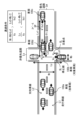
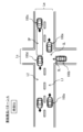
- FIG. 4 is a diagram showing an example of a passing condition at an intersection.
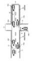
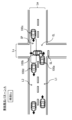
- FIG. 5 is a diagram showing an example of a region in the vicinity of an intersection where the number of vehicles is to be counted.
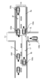
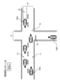
- FIG. 6 is a diagram showing a modified example of a region in the vicinity of an intersection where the number of vehicles is to be counted.
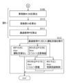
- FIG. 7 is a diagram showing a modified example of the driving assistance procedure following FIG. FIG.
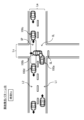
- FIG. 8 is a diagram showing an example of a traffic situation near an intersection.
- FIG. 9 is a diagram showing an example of a traffic situation near an intersection.
- FIG. 10 is a diagram showing an example of a traffic situation near an intersection.
- FIG. 11 is a diagram showing an example of a traffic situation near an intersection.
- FIG. 12 is a diagram showing an example of a traffic situation near an intersection.
- FIG. 13 is a diagram showing an example of a traffic situation near an intersection.
- Patent Document 1 discloses a technology that predicts the driving intentions of the drivers of the vehicles traveling around the vehicle (surrounding vehicles) from the positions and driving parameters (speed, etc.) of the surrounding vehicles, and estimates whether or not any of the surrounding vehicles are likely to merge into the lane in which the vehicle is traveling.
- the invention described in Patent Document 2 discloses a technology that identifies a vehicle to be merged that will be a following vehicle that will merge on a priority road, and if the distance between the vehicle and the to-be-merged vehicle is less than the safe merging distance, determines the traffic conditions in front of and behind the to-be-merged vehicle and decides whether the vehicle should merge.
- Patent Document 3 discloses a technology that predicts the behavior of a moving object based on dynamic information of the moving object generated based on sensor data collected from multiple sensors, and determines a combination of actions that may result in a collision between the moving objects based on the predicted behavior.
- the invention described in Patent Document 4 discloses a technology that predicts a moving object that may appear from a blind spot, and calculates a speed range in which the vehicle may come into contact with the moving object based on the assumed speed of the predicted moving object.
- each of Patent Documents 1 to 4 only estimate the movement of the other vehicle based on whether or not there is a possibility of a collision using parameters such as the vehicle speed and distance between the other vehicle, and do not take into account parameters that have a high correlation with the psychological state of the driver of the other vehicle. Therefore, the inventions described in each of Patent Documents 1 to 4 are theoretically unable to predict that the other vehicle may merge or change lanes due to the psychological influence of the driver of the other vehicle, even if the other vehicle is very unlikely to merge or change lanes. As a result, the inventions described in Patent Documents 1 to 4 deal with the situation only after the other vehicle begins to merge or change lanes, so there is a high possibility of an accident occurring in which your vehicle collides with the other vehicle.
- FIGs. 8, 9, and 10 show hypothetical examples of traffic conditions.
- vehicle (own vehicle) 100a is traveling on a road with one lane on each side.
- This road with one lane on each side is composed of a driving lane L1 in which vehicle 100a is traveling, and an oncoming lane L2 that is provided along the driving lane L1 via a center line.
- An intersection CL is provided in front of vehicle 100a on this road with one lane on each side.
- This road with one lane on each side is a priority road Lm in relation to the road that intersects with this road with one lane on each side at the intersection CL.
- vehicle 100a is traveling on the priority road Lm.
- the road that intersects with the priority road Lm at the intersection CL is a non-priority road Ls in relation to the priority road Lm.
- vehicle (target vehicle) 100b is stopped at a stop line SL (waiting point) (Fig. 8, time ta). There are no traffic lights at intersection CL.
- vehicle 100a recognizes that vehicle 100a is traveling on the priority road Lm. Therefore, vehicle 100a is about to enter intersection CL without decelerating.
- vehicle 100b is stopped at the stop line SL (waiting point) on the non-priority road Ls.
- the driver of vehicle 100b intends to pass (cross) the intersection CL or turn left (merge into the oncoming lane L2) at the intersection CL.
- vehicle 100b is stopped at the stop line SL (waiting point) on the non-priority road Ls
- the driver of vehicle 100b is searching for the timing to pass through the intersection CL or turn left at the intersection CL.
- the driver of vehicle 100b finds a wide space SP between vehicles 100c and 100d in the lane proceeding to the left (oncoming lane L2) on the priority road Ls.
- the driver of vehicle 100b decides to use this space SP to pass through intersection CL or to turn left at intersection CL, and starts to enter vehicle 100b into intersection CL ( Figure 9, time tb).
- the driver of vehicle 100b is distracted by using the found space SP to pass through intersection CL or to turn left at intersection CL, and inadvertently overlooks the presence of vehicle 100a.
- vehicle (own vehicle) 100a is traveling on a road with one lane on each side.
- This road with one lane on each side is composed of a driving lane L1 in which vehicle 100a is traveling, and an oncoming lane L2 that is provided along driving lane L1 via a center line.
- An intersection CL is provided in front of vehicle 100a on this road with one lane on each side.
- This road with one lane on each side is a priority road Lm in relation to the road that intersects with this road with one lane on each side at intersection CL.
- vehicle 100a is traveling on the priority road Lm.
- the road that intersects with priority road Lm at intersection CL is a non-priority road Ls in relation to priority road Lm.
- the vehicle (target vehicle) 100b is traveling far ahead of the stop line SL (waiting point) ( Figure 11, time ta). There are no traffic lights at the intersection CL.
- the driver of vehicle 100a is aware that vehicle 100a is traveling on the priority road Lm. Therefore, vehicle 100a is about to enter intersection CL without slowing down. At this time, vehicle 100b is traveling much further ahead than the stop line SL (waiting point) on the non-priority road Ls. The driver of vehicle 100b intends to pass through intersection CL a short distance ahead or to turn left at intersection CL. While driving vehicle 100b on the non-priority road Ls, the driver of vehicle 100b is searching for the right timing to pass through intersection CL or to turn left at intersection CL. At this time, the driver of vehicle 100b finds space SP in the lane (oncoming lane L2) proceeding to the left on the priority road Ls.
- the driver of vehicle 100b decides to use this space SP to pass through intersection CL or to turn left at intersection CL, and starts to enter vehicle 100b into intersection CL without stopping at stop line SL ( FIG. 12 , time tb). At this time, the driver of vehicle 100b is distracted by using the found space SP to pass through intersection CL or to turn left at intersection CL, and inadvertently overlooks the presence of vehicle 100a.
- the inventors of the present application therefore came up with the idea of predicting the behavior of vehicle 100b using parameters that have a high correlation with the psychological state of the driver of vehicle 100b, such as the waiting time and margin time of vehicle 100b, as a measure to reduce the risk of collision between vehicle 100a and vehicle 100b under specific traffic conditions in which vehicle 100a and vehicle 100b are about to enter intersection CL where priority road Lm and non-priority road Ls intersect.
- the driving control system for achieving this will be described in detail below.
- Fig. 1 shows a schematic configuration example of a cruise control system 1 according to an embodiment of the present disclosure.
- the cruise control system 1 includes cruise control devices 10 mounted on a plurality of vehicles, and a control device 200 provided in a network environment NW to which the plurality of cruise control devices 10 are connected via wireless communication.
- the cruise control device 10 corresponds to a specific example of a "driving assistance device" according to an embodiment of the present disclosure.
- the control device 200 sequentially integrates and updates the road map information transmitted from the driving control device 10 of each vehicle, and transmits the updated road map information to each vehicle.
- the control device 200 has, for example, a road map information integration_ECU 201 and a transceiver 202.
- the road map boundary information integration ECU 201 integrates road map information collected from multiple vehicles via the transceiver 202, and sequentially updates the road map information surrounding the vehicle on the road.
- the road map information is, for example, a dynamic map, and has static information and quasi-static information that mainly constitute road information, and quasi-dynamic information and dynamic information that mainly constitute traffic information.
- the static information that makes up road information is composed of information that requires updates within one month, such as roads, structures on roads, structures around roads, lane information, road surface information, and permanent regulation information.
- roads include, for example, road locations and shapes, intersections, and road attributes (for example, national roads, prefectural roads, city roads, private roads, priority roads, non-priority roads, general roads, and expressways).
- Structures on roads include, for example, traffic signs, traffic lights, convex mirrors, and pedestrian bridges.
- Structures around roads include, for example, various buildings and parks.
- the semi-static information that makes up road information is made up of information that needs to be updated within one hour, such as traffic regulation information due to road construction or events, wide-area weather information, and traffic congestion forecasts.
- the semi-dynamic information that makes up traffic information is made up of information that requires updates within one minute, such as the actual traffic congestion situation at the time of observation, driving restrictions, temporary driving impediments such as fallen objects and obstacles, actual accident conditions, and narrow-area weather information.
- the dynamic information that constitutes the traffic information is composed of information that requires updating every second, such as information sent and exchanged between moving objects, information on currently displayed traffic signals, information on pedestrians and bicycles at intersections, and information on vehicles traveling on roads.
- Such road map information is maintained and updated periodically until the next information is received from each vehicle, and the updated road map information is appropriately transmitted to each vehicle via the transceiver 202.
- the driving control device 10 has a driving environment recognition unit 11 and a locator unit 12 as units for recognizing the driving environment around the vehicle.
- the driving control device 10 also has a driving control unit (hereinafter referred to as the "driving_ECU") 21, an engine control unit (hereinafter referred to as the “E/G_ECU”) 22, a power steering control unit (hereinafter referred to as the "PS_ECU”) 23, and a brake control unit (hereinafter referred to as the "BK_ECU”) 24.
- driving_ECU driving control unit
- E/G_ECU engine control unit
- PS_ECU power steering control unit
- BK_ECU brake control unit
- the travel_ECU 21 controls the vehicle according to, for example, the driving mode.
- the driving modes include a manual driving mode and a driving control mode.
- the manual driving mode is a driving mode that requires the driver to maintain the steering wheel, and is a driving mode in which the vehicle is driven according to the driver's driving operations, such as steering, accelerator, and brake operations.
- the driving control mode is a driving mode that supports the driver in driving operations by the driver to increase the safety of pedestrians and other vehicles around the vehicle (the vehicle itself).
- the driving_ECU 21 predicts the behavior of a traveling or stopped vehicle (hereinafter referred to as a "target vehicle") on a road that intersects at the intersection, and when the prediction results in a high possibility that the target vehicle will enter the intersection, it is possible to, for example, alert or warn the driver, and even perform risk avoidance control such as braking.
- a traveling or stopped vehicle hereinafter referred to as a "target vehicle”
- a throttle actuator 25 is connected to the output side of the E/G_ECU 22. This throttle actuator 25 opens and closes the throttle valve of an electronically controlled throttle provided in the throttle body of the engine.
- the E/G_ECU 22 controls the operation of the throttle actuator 25 by outputting a drive signal to the throttle actuator 25.
- the throttle actuator 25 opens and closes the throttle valve based on the drive signal from the E/G_ECU 22 to adjust the intake air flow rate, thereby generating the desired engine output.
- An electric power steering motor 26 is connected to the output side of the PS_ECU 23. This electric power steering motor 26 applies steering torque to the steering mechanism by the rotational force of the motor.
- the PS_ECU 23 controls the operation of the electric power steering motor 26 by outputting a drive signal to the electric power steering motor 26.
- the electric power steering motor 26 performs lane keeping control, which keeps the vehicle traveling in the current lane, and lane change control, which moves the vehicle to an adjacent lane (lane change control for overtaking control, etc.), based on the drive signal from the PS_ECU 23.
- a brake actuator 27 is connected to the output side of the BK_ECU 24. This brake actuator 27 adjusts the brake hydraulic pressure supplied to the brake wheel cylinders provided on each wheel.
- the BK_ECU 24 controls the operation of the brake actuator 27 by outputting a drive signal to the brake actuator 27. Based on the drive signal from the BK_ECU 24, the brake actuator 27 generates a braking force on each wheel using the brake wheel cylinders, forcibly slowing down the wheels.
- the driving environment recognition unit 11 is fixed, for example, to the center of the upper part of the interior front of the vehicle.
- This driving environment recognition unit 11 has an on-board camera (stereo camera) consisting of a main camera 11a and a sub-camera 11b, an image processing unit (IPU) 11c, and a driving environment detection unit 11d.
- stereo camera stereo camera
- IPU image processing unit
- the main camera 11a and the sub-camera 11b are autonomous sensors that sense the real space around the vehicle.
- the main camera 11a and the sub-camera 11b are, for example, arranged at symmetrical positions on either side of the central part in the width direction of the vehicle, making it possible to capture stereo images of the area in front of the vehicle from different viewpoints.
- the IPU 11c is capable of generating a distance image calculated from the amount of deviation in the positions of corresponding objects based on a pair of stereo images of the area in front of the vehicle captured by the main camera 11a and the sub-camera 11b.
- the driving environment detection unit 11d can, for example, determine the lane markings that divide the road around the vehicle based on the distance image received from the IPU 11c.
- the driving environment detection unit 11d can also, for example, determine the road curvature [1/m] of the markings that divide the left and right sides of the road (driving lane) on which the vehicle is traveling, and the width between the left and right markings (vehicle width).
- the driving environment detection unit 11d can also, for example, perform a predetermined pattern matching on the distance image to detect lanes and three-dimensional objects such as structures that exist around the vehicle.
- the driving environment detection unit 11d when detecting a three-dimensional object in the driving environment detection unit 11d, for example, the type of the three-dimensional object, the distance to the three-dimensional object, the speed of the three-dimensional object, and the relative speed between the three-dimensional object and the vehicle (host vehicle) are detected.
- three-dimensional objects to be detected include traffic lights, intersections, road signs, stop lines, other vehicles, pedestrians, and various buildings.
- the driving environment detection unit 11d is capable of outputting information about the detected three-dimensional objects to the driving_ECU 21, for example.
- the locator unit 12 estimates the position of the vehicle (own vehicle position) on a road map, and has a locator calculation unit 13 that estimates the own vehicle position. Sensors required for estimating the vehicle position (own vehicle position) are connected to the input side of this locator calculation unit 13. Such sensors include, for example, an acceleration sensor 14, a vehicle speed sensor 15, a gyro sensor 16, and a GNSS receiver 17.
- the acceleration sensor 14 is capable of detecting the longitudinal acceleration of the vehicle.
- the vehicle speed sensor 15 is capable of detecting the speed of the vehicle.
- the gyro sensor 16 is capable of detecting the angular velocity or angular acceleration of the vehicle.
- the GNSS receiver 17 is capable of receiving positioning signals transmitted from a plurality of positioning satellites.
- a transceiver 18 is connected to the locator calculation unit 13 for transmitting and receiving information to and from the control device 200, as well as transmitting and receiving information to and from other vehicles.
- a high-precision road map database 19 is connected to the locator calculation unit 13.
- the high-precision road map database 19 is a large-capacity storage medium such as an HDD, and stores high-precision road map information (dynamic map).
- This high-precision road map information like the road map information contained in the road map information integration_ECU 201, has static information and quasi-static information that mainly constitute road information, and quasi-dynamic information and dynamic information that mainly constitute traffic information.
- the locator calculation unit 13 includes, for example, a map information acquisition unit 13a, a vehicle position estimation unit 13b, and a driving environment recognition unit 13c.
- the vehicle position estimation unit 13b is capable of acquiring the position coordinates of the vehicle (own vehicle) based on the positioning signal received by the GNSS receiver 17.
- the vehicle position estimation unit 13b is also capable of estimating the vehicle's position on the road map by map matching the acquired position coordinates on the route map information.
- the map information acquisition unit 13a is capable of acquiring map information of a predetermined range including the vehicle (own vehicle) from map information stored in the high-precision road map database 19, based on the position coordinates of the vehicle (own vehicle) acquired by the vehicle position estimation unit 13b.
- the vehicle position estimation unit 13b can estimate the vehicle's position on a road map by switching to autonomous navigation, which estimates the vehicle's position based on the vehicle speed detected by the vehicle speed sensor 15, the angular velocity detected by the gyro sensor 16, and the longitudinal acceleration detected by the acceleration sensor 14.
- the vehicle position estimation unit 13b estimates the position of the vehicle (host vehicle position) on a road map based on the positioning signal received by the GNSS receiver 17 or information detected by the gyro sensor 16, etc., and is then able to determine the road type, etc. of the road on which the vehicle (host vehicle) is traveling based on the estimated host vehicle position on the road map.
- the driving environment recognition unit 13c is capable of updating the road map information stored in the high-precision road map database 19 to the latest state using road map information acquired by external communication (roadside-to-vehicle communication and vehicle-to-vehicle communication) via the transceiver 18.
- This information update is performed not only for static information, but also for quasi-static information, quasi-dynamic information, and dynamic information.
- the road map information is composed of road information and traffic information acquired by communication outside the vehicle, and information on moving bodies such as vehicles traveling on roads is updated in approximately real time.
- the driving environment recognition unit 13c verifies road map information based on the driving environment information recognized by the driving environment recognition unit 11, and is capable of updating the road map information stored in the high-precision road map database 19 to the latest state.
- This information update is performed not only for static information, but also for quasi-static information, quasi-dynamic information, and dynamic information. As a result, information on moving objects such as vehicles traveling on roads recognized by the driving environment recognition unit 11 is updated in real time.
- the road map information thus updated is then transmitted to the control device 200 and vehicles surrounding the vehicle (the vehicle itself) by road-to-vehicle communication and vehicle-to-vehicle communication via the transceiver 18. Furthermore, the driving environment recognition unit 13c is capable of outputting, from the updated road map information, map information of a predetermined range including the vehicle's position estimated by the vehicle position estimation unit 13b, together with the vehicle's position (vehicle position information) to the driving_ECU 21.
- FIGS. 2 and 3 show an example of a driving assistance procedure in the cruise control system 1.
- FIG. 4 shows an example of a traffic situation in steps S101 to S108 in FIG. 2.
- FIG. 5 shows an example of two areas (nearby area Ra, evaluation target area Rb) defined for calculating the passing probability P in steps S109 to S111 in FIG. 3.
- FIG. 4 shows an example of the conditions (passing conditions) for the vehicle 100b (target vehicle) to pass through the space SP.
- the passing probability P refers to the possibility that the vehicle 100b will enter the space SP.
- vehicle (host vehicle) 100a is traveling on a road with one lane in each direction.
- Vehicle 100a corresponds to a specific example of a "first vehicle” according to an embodiment of the present disclosure.
- This road with one lane in each direction is composed of a driving lane L1 in which vehicle 100a is traveling, and an oncoming lane L2 that is provided along driving lane L1 with a center line interposed therebetween.
- An intersection CL is provided ahead of vehicle 100a on this road with one lane in each direction.
- This road with one lane in each direction is a priority road Lm in relation to the road that intersects with this road with one lane in each direction at the intersection CL. In other words, vehicle 100a is traveling on the priority road Lm.
- the road that intersects with the priority road Lm at the intersection CL is a non-priority road Ls in relation to the priority road Lm.
- a vehicle (target vehicle) 100b is stopped at a stop line SL (waiting point) or traveling toward the intersection CL.
- Vehicle 100b corresponds to a specific example of a "second vehicle" according to an embodiment of the present disclosure.
- vehicle 100a recognizes that vehicle 100a is traveling on the priority road Lm. Therefore, vehicle 100a is about to enter intersection CL without decelerating.
- vehicle 100b is stopped at the stop line SL (waiting point) on the non-priority road Ls or traveling toward intersection CL.
- the driver of vehicle 100b intends to pass through intersection CL or turn left at intersection CL.
- vehicle 100b is stopped at the stop line SL (waiting point) on the non-priority road Ls or traveling toward intersection CL, the driver of vehicle 100b is searching for the timing to pass through intersection CL or turn left at intersection CL.
- the driver of vehicle 100b finds a wide space SP between vehicles 100c and 100d in the lane proceeding to the left (oncoming lane L2) on the priority road Ls.
- the driver of vehicle 100b decides to use this space SP to pass through intersection CL or to turn left at intersection CL, and enters vehicle 100b into intersection CL.
- the driver of vehicle 100b is distracted by using the space SP he found to pass through intersection CL or to turn left at intersection CL, and inadvertently overlooks the presence of vehicle 100a.
- the travel_ECU 21 is therefore capable of performing calculations that take such events into consideration. Specifically, the travel_ECU 21 is capable of determining whether or not a specific traffic situation is occurring in which the vehicles 100a and 100b are attempting to enter an intersection CL where the priority road Lm and the non-priority road Ls intersect. After determining that a specific traffic situation is occurring, the travel_ECU 21 performs calculations regarding the existence of a space SP (entry space) into which the vehicle 100b can enter, and the waiting time Tw or margin time Ts of the vehicle 100b, and is capable of predicting the possibility (passing probability P) that the vehicle 100b will enter the space SP based on the results of the calculations.
- a space SP entity space
- Tw or margin time Ts of the vehicle 100b is capable of predicting the possibility (passing probability P) that the vehicle 100b will enter the space SP based on the results of the calculations.
- the space SP refers to a space formed by two vehicles adjacent to each other in a common lane (for example, the oncoming lane L2).
- the "space SP (entry space) into which the vehicle 100b can enter” refers to a space having a width (length) into which the vehicle 100b can theoretically enter when the vehicle 100b is stopped at the stop line SL or traveling toward the intersection CL.
- the "entry space” must exist at least within a range that can be recognized by the driver of the vehicle 100b. Therefore, the "entry space” must exist within an area with a radius of about 50 m centered on the vehicle 100b, for example.
- the travel_ECU 21 is capable of determining whether or not a space SP that satisfies the following passing conditions (1) and (2) exists among one or more spaces SP formed by two adjacent vehicles in the oncoming lane L2 of the priority road Ls.
- the passing conditions (1) and (2) are expressed as equations as shown in the following paragraph.
- the travel_ECU 21 is capable of determining that space SP as a space SP into which the vehicle 100b can enter (entry space).
- Vehicle 100b does not come into contact with vehicle 100d, and after vehicle 100d passes through intersection CL, vehicle 100b passes through space SP or merges into space SP.
- Vehicle 100b passes through the intersection CL without coming into contact with vehicle 100c, or after vehicle 100b passes through the space SP or merges into the space SP, vehicle 100c passes through intersection CL.
- Vx1 Vehicle speed [m/s]
- Vx2 Vehicle 100d speed [m/s]
- Vy Velocity of vehicle 100b [m/s]
- Lx1 Distance [m] between the rear end of the space SP and the point (intersection point ⁇ ) where the vehicles 100c and 100b intersect within the intersection CL.
- Lx2 Distance [m] between the front end of the space SP and the point (intersection point ⁇ ) where the vehicles 100c and 100b intersect within the intersection CL.
- Ly The sum of the width [m] of the priority road Lm at the intersection CL and the total length [m] of the vehicle 100b [m]
- Wr Width of priority road Lm [m]
- Wb 1/2 the width of the non-priority road Ls [m]
- Wd 1/2 the width of the priority road Lm [m]
- Ls1 Distance from the stop line SL to the priority road Lm within the intersection SL [m] (Wr/2+Ls1)/Vy: time [s] required for the vehicle 100b to travel from the stop line SL to the oncoming lane L2 in the intersection CL (Lx2+Wb/2)/Vx2: time [s] required for the vehicle 100d to pass through the intersection CL from its current position Ly/Vy: time [s] required for the vehicle 100b to move from the position of the stop line SL to the position where it passes through the intersection CL (the position of the vehicle indicated by the dashed line in FIG. 4) (Lx1-Wb/2)/Vx1
- Examples of traffic situations in which it can be said that "there is no entry space” include the traffic situations shown below.
- the driving_ECU 21 can estimate whether the traffic conditions ahead of the vehicle 100a are as described above, for example, from data obtained from a sensor of the vehicle 100a (e.g., the driving environment recognition unit 11), data obtained from a road surface sensor through road-to-vehicle communication by the receiver-transmitter 18, or data obtained from another vehicle through vehicle-to-vehicle communication by the receiver-transmitter 18. If these data include, for example, data indicating that multiple vehicles are traveling without interruption in the oncoming lane L2, the driving_ECU 21 can determine that the traffic conditions ahead of the vehicle 100a are as described above.
- the waiting time Tw refers to the time that the vehicle 100b is stopped at the stop line SL. This time refers to the time (predicted time) that the vehicle 100b stopped at the stop line SL is predicted to spend from the time when the vehicle 100b stops at the stop line SL until it departs from the stop line SL, or the actual time that has a predetermined correlation with the predicted time.
- the start timing of the predicted time and the actual measurement time may include various timings, for example, as shown below.
- the start timing of the predicted time and the actual measurement time may be, for example, the timing when the vehicle 100b stops at the stop line SL, or the timing when measurement of the predicted time and the actual measurement time starts while the vehicle 100b is stopped at the stop line SL.
- the start timing of the predicted time and the actual measurement time may be, for example, the timing when an "entry space" is detected while the vehicle 100b is stopped at the stop line SL.
- the start timing of the predicted time and the actual measurement time may be, for example, the timing when the vehicle 100b is detected to be stopped at the stop line SL, or the timing when the vehicle 100b stopped at the stop line SL is detected.
- the timing at which the actual measurement time ends may be, for example, the timing at which the travel_ECU 21 starts calculating the waiting time Tw (the timing at which step S110 described below starts).
- the timing at which the travel_ECU 21 starts calculating the waiting time Tw is a predetermined period of time before the vehicle 100b actually departs from the stop line SL.
- the timing at which the actual measurement time ends is not limited to the timing at which step S110 described below starts.
- the driving_ECU 21 is capable of calculating the waiting time Tw (predicted time or actual measured time) based on, for example, data obtained from a sensor (e.g., the driving environment recognition unit 11) of the vehicle 100a, data obtained from a road surface sensor through road-to-vehicle communication by the receiver-transmitter 18, or data obtained from another vehicle through vehicle-to-vehicle communication by the receiver-transmitter 18.
- a sensor e.g., the driving environment recognition unit 11
- the margin time Ts refers to a margin time when the vehicle 100b enters the "entry space".
- the margin time Ts is, for example, the difference between the time when the vehicle 100b is predicted to reach the "entry space” and the current time.
- the margin time Ts may be, for example, a time that has a predetermined correlation with the difference between the time when the vehicle 100b is predicted to reach the "entry space” and the current time.
- the margin time Ts may be, for example, a time that has a predetermined correlation with the difference between the time when the vehicle 100b is predicted to reach the stop line SL and the current time.
- the driving_ECU 21 is capable of calculating the waiting time Tw (predicted time or actual measured time) based on, for example, data obtained from a sensor (e.g., the driving environment recognition unit 11) of the vehicle 100a, data obtained from a road surface sensor through road-to-vehicle communication by the receiver-transmitter 18, or data obtained from another vehicle through vehicle-to-vehicle communication by the receiver-transmitter 18.
- a sensor e.g., the driving environment recognition unit 11
- the passing probability P refers to the possibility that the vehicle 100b will enter the space SP.
- the passing probability P can be derived, for example, by the following formula (1) or formula (2).
- Formula (1) is a formula for deriving the passing probability P when the vehicle 100b is stopped at the stop line SL.
- Formula (2) is a formula for deriving the passing probability P when the vehicle 100b is traveling on the non-priority road Ls.
- N1 number of vehicles in the neighborhood area Ra (number of partial recognition loads)
- N2 Number of vehicles in the evaluation target area Rb (total recognized load number)
- Figure 5 shows an example of a counting area for the number of vehicles near intersection CL.
- Figure 5 shows examples of a nearby area Ra and an evaluation area Rb as counting areas.
- Nearby area Ra is an area on priority road Lm near space SP (entry space) into which vehicle 100b can enter.
- nearby area Ra includes two vehicles (e.g., vehicles 100c, 100d) that make up the entry space, and a vehicle (e.g., vehicle 100e) traveling in the area between the entry space and vehicle 100b in the lane (traveling lane L1) between the entry space and vehicle 100b. Therefore, the number of vehicles N1 is three in Figure 5.
- Evaluation area Rb is an area in front of vehicle 100a on priority road Lm, and includes vehicle 100a and nearby area Ra.
- the evaluation target area Rb includes vehicles 100c, 100d, vehicle 100e, vehicle 100a, and vehicle 100f traveling beside vehicle 100a. Therefore, the number of vehicles N2 in FIG. 5 is 5.
- the driving_ECU 21 is capable of calculating the passing probability P based on, for example, data obtained from a sensor (e.g., the driving environment recognition unit 11) of the vehicle 100a, data obtained from a road surface sensor through road-to-vehicle communication by the receiver-transmitter 18, or data obtained from another vehicle through vehicle-to-vehicle communication by the receiver-transmitter 18.
- the timing for calculating the number of vehicles N1 and the number of vehicles N2 is, for example, the timing when it is determined that there is a space SP (entry space) into which the vehicle 100b can enter, that is, the timing when step S108 described below is executed.
- a driving assistance procedure in the driving control system 1 will be described with reference to Figures 2 and 3.
- a stereo camera provided on the vehicle 100a captures an image of the area ahead of the vehicle 100a, and outputs the resulting stereo image to the IPU 11c.
- the IPU 11c generates a distance image based on the stereo image captured by the stereo camera, and outputs the image to the driving environment detection unit 11d.
- the driving environment detection unit 11d performs a predetermined pattern matching or the like on the distance image generated by the IPU 11c, and detects the priority road Lm, the driving lane L1, the oncoming lane L2, the non-priority road Ls, the intersection CL, vehicles on the priority road Lm (e.g., vehicles 100a, 100c to 100f), and vehicles on the non-priority road Ls (e.g., vehicle 100b).
- the driving environment recognition unit 13c uses the road map information acquired from external communication to detect the priority road Lm, the driving lane L1, the oncoming lane L2, the non-priority road Ls, the intersection CL, vehicles on the priority road Lm (e.g., vehicles 100a, 100c to 100f), and vehicles on the non-priority road Ls (e.g., vehicle 100b).
- the road map information acquired from external communication includes information on vehicles on the priority road Lm (e.g., vehicles 100a, 100c to 100f) and vehicles on the non-priority road Ls (e.g., vehicle 100b).
- the driving environment recognition unit 13c can detect vehicles on the priority road Lm (e.g., vehicles 100a, 100c to 100f) and vehicles on the non-priority road Ls (e.g., vehicle 100b) using the road map information acquired from external communication.
- the priority road Lm e.g., vehicles 100a, 100c to 100f
- the non-priority road Ls e.g., vehicle 100b
- the vehicle position estimation unit 13b acquires the position coordinates of the vehicle 100a based on the positioning signal received by the GNSS receiver 17. The vehicle position estimation unit 13b further acquires the vehicle speed (the speed of the vehicle 100a) detected by the vehicle speed sensor 15.
- the driving_ECU 21 acquires road information Da and vehicle information Db based on various information obtained from the driving environment detection unit 11d, the vehicle position estimation unit 13b, and the driving environment recognition unit 13c (step S101).
- the road information Da includes information on the priority road Lm, the driving lane L1, the oncoming lane L2, the non-priority road Ls, and the intersection CL detected by the driving environment detection unit 11d or the driving environment recognition unit 13c.
- the vehicle information Db includes information on the speed (vehicle speed) of the vehicle 100a acquired from the vehicle position estimation unit 13b, and information on vehicles on the priority road Lm (e.g., vehicles 100a, 100c to 100f) and vehicles on the non-priority road Ls (e.g., vehicle 100b) acquired from the driving environment detection unit 11d or the driving environment recognition unit 13c.
- vehicles on the priority road Lm e.g., vehicles 100a, 100c to 100f
- vehicles on the non-priority road Ls e.g., vehicle 100b
- the driving_ECU 21 determines whether an intersection CL exists ahead of the vehicle 100a (step S102). If the road information Da includes information on the intersection CL (step S102; Y), the driving_ECU 21 determines whether the lane on which the vehicle 100a is traveling (driving lane L1) is a priority road Lm (step S103). If the road information Da includes information on the priority road Lm (step S103; Y), the driving_ECU 21 determines whether a vehicle (target vehicle) 100b traveling on a non-priority road Ls exists (step S104).
- the driving_ECU 21 calculates the inter-vehicle space ⁇ L formed by multiple vehicles traveling on the oncoming lane L2 of the priority road Lm (step S105). If the calculated inter-vehicle space ⁇ L is equal to or greater than a predetermined threshold ⁇ Lth (step S106; Y), the travel_ECU 21 recognizes the space having an inter-vehicle space ⁇ L equal to or greater than the threshold ⁇ Lth as the above-mentioned space SP.
- the travel_ECU 21 then calculates the passing conditions for the space SP (step S107). If the space SP satisfies the passing conditions (step S108; Y), it calculates the number of vehicles N1, N2, the waiting time Tw or margin time Ts, and the passing probability P (steps S109, S110, S111).
- the traveling_ECU 21 executes step S101 if any of the following conditions is met in each of the above steps.
- step S102; N When the road information Da does not include information on the intersection CL (step S102; N)
- step S103; N When the road information Da does not include information on the priority road Lm
- step S104; N When the vehicle information Db does not include information on the vehicle 100b (step S104; N)
- step S106; N When the vehicle space ⁇ L is less than the threshold value ⁇ Lth (step S106; N)
- the space SP does not satisfy the passing condition
- the traveling_ECU 21 executes driving assistance according to the passing probability P (step S112).
- the traveling_ECU 21 does not execute any driving assistance.
- the driving_ECU 21 alerts the driver of the vehicle 100a.
- the driving_ECU 21 outputs a video signal to a head-up display that displays an image on the windshield, in which a shape image with a color (e.g., yellow) indicating the presence of the vehicle 100b on the non-priority road Ls is superimposed.
- a shape image with a color e.g., yellow
- the driving_ECU 21 issues a warning to the driver of the vehicle 100a.
- the driving_ECU 21 outputs a video signal to a head-up display that displays an image on the front window, in which a form image with a color (e.g., red) that indicates the presence of the vehicle 100b on the non-priority road Ls is superimposed.
- the driving_ECU 21 outputs an audio signal that produces an intermittent sound to the speaker.
- the travel_ECU 21 performs risk avoidance control such as braking on the vehicle 100a.
- the travel_ECU 21 performs a predetermined risk avoidance braking when there is 3 seconds or less until a collision between the vehicles 100a and 100b. This makes it possible to avoid a collision between the vehicles 100a and 100b.
- data is acquired indicating that vehicle 100b exists, that a plurality of vehicles exist in at least one lane (traveling lane L1, oncoming lane L2) ahead of vehicle 100a, and that a space SP (entry space) into which vehicle 100b can enter exists in one or more spaces formed by two vehicles adjacent to each other in a common lane (oncoming lane L2). Then, when vehicle 100b is waiting at stop line SL, the waiting time Tw of vehicle 100b is estimated based on the acquired data. When vehicle 100b is traveling toward stop line SL, the margin time Ts when vehicle 100b enters the entry space is estimated based on the acquired data.
- the possibility (passing probability P) of vehicle 100b entering the entry space is predicted based on the waiting time Tw or margin time Ts. This makes it possible to predict the possibility that vehicle 100b will pass through intersection CL due to the psychological influence of the driver of vehicle 100b. As a result, it is possible to issue warnings, perform braking control, and perform other actions that can avoid a collision between vehicles 100a and 100b.
- the possibility (passing probability P) of vehicle 100b entering the entry space is predicted based on the number of vehicles N1, N2, the waiting time Tw, or the margin time Ts. This makes it possible to predict the possibility that vehicle 100b will pass through intersection CL due to the psychological influence of the driver of vehicle 100b. As a result, it is possible to perform attention calls, warnings, braking control, etc. that can avoid a collision between vehicles 100a and 100b.
- the possibility (passage probability P) that vehicle 100b will enter the entry space can be predicted even when vehicle 100a has difficulty communicating with the network environment NW.
- the possibility (passing probability P) of vehicle 100b entering the entry space can be predicted more accurately than when road information Da and vehicle information Db are generated only by sensors installed on vehicle 100a.
- the evaluation target area Rb may be, for example, an area including the vicinity area Ra and the area from the position of the vehicle 100a to the entry space in the lane (traveling lane L1) on which the vehicle 100a is traveling, as shown in Fig. 6.
- the number of vehicles traveling in an area that is relatively less affected by the entry of the vehicle 100b into the entry space can be excluded from the number of vehicles N2.
- the traveling_ECU 21 may be capable of predicting the possibility (passing probability P) of the vehicle 100b entering the entry space based on the congestion degree Cd of the nearby area Ra and the evaluation target area Rb, instead of the waiting time Tw and the margin time Ts, for example, as shown in step S113 of Figure 7.
- the present disclosure is applied to driving assistance at an intersection CL where a priority road Lm and a non-priority road Ls intersect.
- the present disclosure may be applied to driving assistance at a junction where a non-priority road Ls merges with a priority road Lm. In such a case, it is possible to predict the possibility that the vehicle 100b will merge due to the psychological influence of the driver of the vehicle 100b, as in the above embodiment and its modified example.
- the travel_ECU 21 may acquire road information Da and vehicle information Db based on various data of the sensor detection area SR obtained from various sensors mounted on the vehicle 100a.
- the road information Da includes information on the priority road Lm, the driving lane L1, the oncoming lane L2, the non-priority road Ls, and the intersection CL detected by the driving environment recognition unit 13c.
- the vehicle information Db includes information on the speed (vehicle speed) of the vehicle 100a acquired from the vehicle position estimation unit 13b, and information on vehicles on the priority road Lm (e.g., vehicles 100a, 100c to 100f) and vehicles on the non-priority road Ls (e.g., vehicle 100b). Even in this case, it is possible to predict the possibility that the vehicle 100b will merge or cross due to the psychological influence of the driver of the vehicle 100b.
- the present disclosure can have the following configuration.
- the control unit is acquiring first data indicating that the prediction target vehicle exists, that a plurality of second vehicles exist in at least one lane ahead of the first vehicle, and that an entry space into which the prediction target vehicle can enter exists in one or more spaces formed by two of the second vehicles adjacent to each other in a common lane;
- the prediction target vehicle is waiting at the waiting point, estimating a waiting time of the prediction target vehicle at the waiting point based on the acquired first data, and when the prediction target vehicle is traveling toward the waiting point, estimating a margin time when the prediction target vehicle enters the entry space based on the acquired first data; and
- the control unit is capable of estimating, based on the acquired first data, a time required for the prediction target vehicle to enter the entry space, or a time having a predetermined correlation with that time, as the margin time.
- the control unit is obtaining second data indicating that the entry space does not exist; and and estimating the waiting time based on the first data and the second data.
- the control unit is estimating the number of vehicles within a predetermined area ahead of the first vehicle based on the acquired first data; and predicting the possibility that the predicted vehicle will enter the entry space based on the number of vehicles and the waiting time or the margin time.
- the control unit estimates, based on the acquired first data, a number N1 of vehicles in the vicinity of the entry space on the priority road, and a number N2 of vehicles in an evaluation target area of the priority road extending from the position of the first vehicle to the vicinity of the entry space;
- the driving assistance device described in (4) is capable of predicting the possibility that the prediction target vehicle will enter the entry space based on the number of vehicles N1, the number of vehicles N2, and the waiting time or the margin time.
- the control unit is Based on the acquired first data, a number N1 of vehicles in the vicinity of the entry space on the priority road and a number N3 of vehicles in an evaluation target area extending from the position of the first vehicle to the vicinity of the entry space in the same lane as the first vehicle are estimated;
- the driving assistance device described in (4) is capable of predicting the possibility that the predicted vehicle will enter the entry space based on the number of vehicles N1, the number of vehicles N3, and the waiting time or the margin time.
- a control unit capable of predicting the behavior of a prediction target vehicle when a non-priority road that merges with or intersects with a priority road having one or more lanes in each direction is present ahead of a first vehicle, and a prediction target vehicle is present on the non-priority road, the prediction target vehicle being parked at a waiting point or traveling toward the waiting point;
- the control unit is acquiring data indicating that the prediction target vehicle exists, that a plurality of second vehicles exist in at least one lane ahead of the first vehicle, and that an entry space into which the prediction target vehicle can enter exists in one or more spaces formed by two of the second vehicles adjacent to each other in a common lane;
- the prediction target vehicle is waiting at the waiting point, estimating a waiting time of the prediction target vehicle at the waiting point based on the acquired data, and when the prediction target vehicle is traveling toward the waiting point, estimating a margin time when the prediction target vehicle enters the entry space based on the acquired data; and predicting the possibility that the prediction target vehicle will enter the entry space
- a driving assistance method capable of predicting a behavior of a prediction target vehicle when a non-priority road that merges with or intersects with a priority road having one or more lanes in each direction is present ahead of a first vehicle, and a prediction target vehicle is present on the non-priority road that is stopped at a waiting point or traveling toward the waiting point, comprising: acquiring data indicating that the prediction target vehicle exists, that a plurality of second vehicles exist in at least one lane ahead of the first vehicle, and that an entry space into which the prediction target vehicle can enter exists in one or more spaces formed by two of the second vehicles adjacent to each other in a common lane; When the prediction target vehicle is waiting at the waiting point, estimating a waiting time of the prediction target vehicle at the waiting point based on the acquired data, and when the prediction target vehicle is traveling toward the waiting point, estimating a margin time when the prediction target vehicle enters the entry space based on the acquired data; predicting a possibility that the prediction target vehicle will enter the entry space based on the waiting time or the
- a control unit capable of predicting the behavior of a prediction target vehicle when a non-priority road that merges with or intersects with a priority road having one or more lanes in each direction is present ahead of a first vehicle, and a prediction target vehicle is present on the non-priority road, the prediction target vehicle being parked at a waiting point or traveling toward the waiting point;
- the control unit is acquiring data indicating that the prediction target vehicle exists, that a plurality of second vehicles exist in at least one lane ahead of the first vehicle, and that an entry space into which the prediction target vehicle can enter exists in one or more spaces formed by two of the second vehicles adjacent to each other in a common lane; estimating a first congestion degree in the vicinity of the entry space on the priority road and a second congestion degree in an evaluation target area of the priority road extending from the position of the first vehicle to the vicinity of the entry space based on the acquired data; and predicting a possibility that the prediction target vehicle will enter the entry space based on the first congestion degree and the second congestion degree.
- control unit capable of predicting the behavior of a prediction target vehicle when a non-priority road that merges with or intersects with a priority road having one or more lanes in each direction is present ahead of a first vehicle, and a prediction target vehicle is present on the non-priority road, the prediction target vehicle being parked at a waiting point or traveling toward the waiting point;
- the control unit is acquiring data indicating that the prediction target vehicle exists, that a plurality of second vehicles exist in at least one lane ahead of the first vehicle, and that an entry space into which the prediction target vehicle can enter exists in one or more spaces formed by two of the second vehicles adjacent to each other in a common lane; estimating a first congestion degree in the vicinity of the entry space on the priority road and a third congestion degree in an evaluation target area extending from the position of the first vehicle to the vicinity of the entry space in the same lane as the first vehicle based on the acquired data; and predicting a possibility that the prediction target vehicle will enter the entry space based on the first congestion degree and the third congestion
Landscapes
- Physics & Mathematics (AREA)
- General Physics & Mathematics (AREA)
- Engineering & Computer Science (AREA)
- Chemical & Material Sciences (AREA)
- Analytical Chemistry (AREA)
- Automation & Control Theory (AREA)
- Mathematical Physics (AREA)
- Transportation (AREA)
- Mechanical Engineering (AREA)
- Traffic Control Systems (AREA)
Abstract
Selon un mode de réalisation de la présente divulgation, un dispositif d'aide à la conduite comprend une unité de commande qui peut prédire le comportement d'un véhicule à prédire. L'unité de commande est capable de réaliser (1), (2) et (3) ci-dessous. (1) Acquérir des premières données indiquant la présence d'un véhicule à prédire, la présence d'une pluralité de seconds véhicules dans au moins une voie devant un premier véhicule, et la présence d'un espace d'entrée à partir duquel le véhicule à prédire pourrait entrer parmi un ou plusieurs espaces formés par deux seconds véhicules adjacents l'un à l'autre dans une voie commune. (2) Lorsque le véhicule à prédire est en attente à un emplacement d'attente, estimer un temps d'attente à l'emplacement d'attente pour le véhicule à prédire sur la base des premières données acquises, et lorsque le véhicule à prédire se déplace vers l'emplacement d'attente, estimer un temps excédentaire pour que le véhicule à prédire puisse entrer dans l'espace d'entrée sur la base des premières données acquises. (3) Prédire la probabilité que le véhicule à prédire entre dans l'espace d'entrée sur la base du temps d'attente ou du temps excédentaire
Priority Applications (2)
| Application Number | Priority Date | Filing Date | Title |
|---|---|---|---|
| PCT/JP2023/030240 WO2025041287A1 (fr) | 2023-08-23 | 2023-08-23 | Dispositif d'aide à la conduite, véhicule, et procédé d'aide à la conduite |
| US19/052,617 US20250191470A1 (en) | 2023-08-23 | 2025-02-13 | Driver assistance apparatus, vehicle, and driver assistance method |
Applications Claiming Priority (1)
| Application Number | Priority Date | Filing Date | Title |
|---|---|---|---|
| PCT/JP2023/030240 WO2025041287A1 (fr) | 2023-08-23 | 2023-08-23 | Dispositif d'aide à la conduite, véhicule, et procédé d'aide à la conduite |
Related Child Applications (1)
| Application Number | Title | Priority Date | Filing Date |
|---|---|---|---|
| US19/052,617 Continuation US20250191470A1 (en) | 2023-08-23 | 2025-02-13 | Driver assistance apparatus, vehicle, and driver assistance method |
Publications (1)
| Publication Number | Publication Date |
|---|---|
| WO2025041287A1 true WO2025041287A1 (fr) | 2025-02-27 |
Family
ID=94731803
Family Applications (1)
| Application Number | Title | Priority Date | Filing Date |
|---|---|---|---|
| PCT/JP2023/030240 Pending WO2025041287A1 (fr) | 2023-08-23 | 2023-08-23 | Dispositif d'aide à la conduite, véhicule, et procédé d'aide à la conduite |
Country Status (2)
| Country | Link |
|---|---|
| US (1) | US20250191470A1 (fr) |
| WO (1) | WO2025041287A1 (fr) |
Citations (7)
| Publication number | Priority date | Publication date | Assignee | Title |
|---|---|---|---|---|
| JP2009230701A (ja) * | 2008-03-25 | 2009-10-08 | Toyota Motor Corp | 運転支援装置 |
| JP2009251759A (ja) * | 2008-04-02 | 2009-10-29 | Toyota Motor Corp | 交差点譲り合い支援システム及び車載情報端末 |
| JP2010170517A (ja) * | 2008-12-22 | 2010-08-05 | Nissan Motor Co Ltd | 車両用障害物回避支援装置および車両用障害物回避支援方法 |
| JP2017182206A (ja) * | 2016-03-28 | 2017-10-05 | パナソニックIpマネジメント株式会社 | 車両状況判定装置、車両状況判定方法、および車両状況判定プログラム |
| WO2020053612A1 (fr) * | 2018-09-13 | 2020-03-19 | 日産自動車株式会社 | Procédé de prédiction de comportement de véhicule et dispositif de prédiction de comportement de véhicule |
| JP2020050323A (ja) * | 2018-09-28 | 2020-04-02 | 株式会社デンソーテン | 自動運転装置および自動運転方法 |
| JP2021170243A (ja) * | 2020-04-16 | 2021-10-28 | 株式会社Subaru | 車両の運転支援装置 |
-
2023
- 2023-08-23 WO PCT/JP2023/030240 patent/WO2025041287A1/fr active Pending
-
2025
- 2025-02-13 US US19/052,617 patent/US20250191470A1/en active Pending
Patent Citations (7)
| Publication number | Priority date | Publication date | Assignee | Title |
|---|---|---|---|---|
| JP2009230701A (ja) * | 2008-03-25 | 2009-10-08 | Toyota Motor Corp | 運転支援装置 |
| JP2009251759A (ja) * | 2008-04-02 | 2009-10-29 | Toyota Motor Corp | 交差点譲り合い支援システム及び車載情報端末 |
| JP2010170517A (ja) * | 2008-12-22 | 2010-08-05 | Nissan Motor Co Ltd | 車両用障害物回避支援装置および車両用障害物回避支援方法 |
| JP2017182206A (ja) * | 2016-03-28 | 2017-10-05 | パナソニックIpマネジメント株式会社 | 車両状況判定装置、車両状況判定方法、および車両状況判定プログラム |
| WO2020053612A1 (fr) * | 2018-09-13 | 2020-03-19 | 日産自動車株式会社 | Procédé de prédiction de comportement de véhicule et dispositif de prédiction de comportement de véhicule |
| JP2020050323A (ja) * | 2018-09-28 | 2020-04-02 | 株式会社デンソーテン | 自動運転装置および自動運転方法 |
| JP2021170243A (ja) * | 2020-04-16 | 2021-10-28 | 株式会社Subaru | 車両の運転支援装置 |
Also Published As
| Publication number | Publication date |
|---|---|
| US20250191470A1 (en) | 2025-06-12 |
Similar Documents
| Publication | Publication Date | Title |
|---|---|---|
| US11731632B2 (en) | Vehicle travel control method and travel control device | |
| JP7040621B2 (ja) | 車両の走行制御方法及び走行制御装置 | |
| JP6677822B2 (ja) | 車両制御装置 | |
| RU2767216C1 (ru) | Способ управления движением транспортного средства и аппаратура управления движением транспортного средства | |
| JP4483589B2 (ja) | 車両用情報提供装置 | |
| JP7431697B2 (ja) | 車両の走行制御装置及び車両の走行制御システム | |
| JP6414221B2 (ja) | 車両の走行制御装置及び方法 | |
| US11964668B2 (en) | Vehicle travel control method and travel control device | |
| JP7163729B2 (ja) | 車両制御装置 | |
| US9026356B2 (en) | Vehicle navigation system and method | |
| CN111433094A (zh) | 车辆控制装置 | |
| CN110053619A (zh) | 车辆控制装置 | |
| CN111527015A (zh) | 车辆控制装置 | |
| JP6007739B2 (ja) | 運転支援装置及び運転支援方法 | |
| CN106097774A (zh) | 车道变更支援装置 | |
| WO2016024317A1 (fr) | Dispositif de commande de déplacement et procédé de commande de déplacement | |
| JP7606383B2 (ja) | 車両の走行制御装置 | |
| JP2014041556A (ja) | 運転支援装置 | |
| JP2018154215A (ja) | 運転支援制御装置 | |
| CN110799403A (zh) | 车辆控制装置 | |
| JP7514166B2 (ja) | 車両の運転支援装置 | |
| JP2005145282A (ja) | 車両走行支援装置 | |
| JP2020045039A (ja) | 車両制御方法及び車両制御装置 | |
| JP7514158B2 (ja) | 運転診断装置 | |
| WO2025041287A1 (fr) | Dispositif d'aide à la conduite, véhicule, et procédé d'aide à la conduite |
Legal Events
| Date | Code | Title | Description |
|---|---|---|---|
| 121 | Ep: the epo has been informed by wipo that ep was designated in this application |
Ref document number: 23949747 Country of ref document: EP Kind code of ref document: A1 |
|
| ENP | Entry into the national phase |
Ref document number: 2025541234 Country of ref document: JP Kind code of ref document: A |
|
| WWE | Wipo information: entry into national phase |
Ref document number: 2025541234 Country of ref document: JP |