WO2025041268A1 - Dispositif de planification de fonctionnement - Google Patents
Dispositif de planification de fonctionnement Download PDFInfo
- Publication number
- WO2025041268A1 WO2025041268A1 PCT/JP2023/030165 JP2023030165W WO2025041268A1 WO 2025041268 A1 WO2025041268 A1 WO 2025041268A1 JP 2023030165 W JP2023030165 W JP 2023030165W WO 2025041268 A1 WO2025041268 A1 WO 2025041268A1
- Authority
- WO
- WIPO (PCT)
- Prior art keywords
- input
- motion planning
- motion
- state
- input sampling
- Prior art date
- Legal status (The legal status is an assumption and is not a legal conclusion. Google has not performed a legal analysis and makes no representation as to the accuracy of the status listed.)
- Pending
Links
Images


Classifications
-
- B—PERFORMING OPERATIONS; TRANSPORTING
- B25—HAND TOOLS; PORTABLE POWER-DRIVEN TOOLS; MANIPULATORS
- B25J—MANIPULATORS; CHAMBERS PROVIDED WITH MANIPULATION DEVICES
- B25J9/00—Program-controlled manipulators
- B25J9/10—Program-controlled manipulators characterised by positioning means for manipulator elements
-
- G—PHYSICS
- G05—CONTROLLING; REGULATING
- G05D—SYSTEMS FOR CONTROLLING OR REGULATING NON-ELECTRIC VARIABLES
- G05D1/00—Control of position, course, altitude or attitude of land, water, air or space vehicles, e.g. using automatic pilots
- G05D1/60—Intended control result
- G05D1/617—Safety or protection, e.g. defining protection zones around obstacles or avoiding hazards
- G05D1/622—Obstacle avoidance
Definitions
- This disclosure relates to a motion planning device, and in particular to a motion planning device for dynamic systems using a sampling method.
- Motion planning problems involve constraints that the target must satisfy, but the sampling method has the advantage of being able to easily handle complex constraints, as it creates a motion plan after determining for each particle whether it is a valid particle that satisfies the constraints (valid particles) or an invalid particle that does not (invalid particles).
- the control input is sampled, then the time evolution of the physical model is calculated, and valid particles are determined for the state constraints, so that the vehicle is controlled so as to optimize the probability of achieving the desired motion using only valid particles.
- the autonomous driving system of Patent Document 2 samples the control input within the constraints of road surface slippage, thereby controlling the vehicle to optimize the probability of achieving the desired motion using only effective particles for the road surface slippage.
- Sampling methods require a large amount of sampling calculations to guarantee the approximation accuracy of the probability density distribution that is approximated based on sampling.
- the time evolution of a physical model after performing input sampling as in Patent Document 1 and determining effective particles that satisfy constraints, if the number of effective particles is small, the approximation accuracy of the probability density distribution cannot be guaranteed. In other words, a decrease in effective particles increases the possibility of a decrease in the functionality of the method.
- Patent Document 2 limits the input sampling in advance, making it easy to ensure a valid number of particles, but since it is limited to road surface slippage, it is difficult to apply it to other applications, and when other state constraints are taken into account, the results are similar to those of Patent Document 1.
- the present disclosure has been made to solve the problems described above, and aims to provide a motion planning device that uses a sampling method that is unlikely to cause a degradation in the functionality of the method due to a decrease in effective particles, and that does not limit the state constraints that must be considered in advance in the system to which it is applied.
- the motion planning device is a motion planning device for a dynamic system using a sampling method, and includes: an action planning unit that outputs a mathematical model that expresses the motion of the dynamic system based on a goal to be achieved by the dynamic system and state constraints of the dynamic system that should be considered in advance; and a motion plan generating unit that restricts an input sampling range based on the mathematical model and the state constraints, and generates a motion plan for the dynamic system by performing a state estimation calculation within the input sampling range based on the mathematical model.
- the motion planning device disclosed herein performs input sampling within the range of state constraints that should be considered in advance, improving the approximation accuracy of the probability density distribution that is approximated based on the sampling, reducing the possibility of the method's functionality deteriorating due to a decrease in effective particles, and not limiting the state constraints that should be considered in advance in the system to which it is applied.
- FIG. 1 is a schematic diagram illustrating a configuration of a moving body equipped with a motion planning device according to a first embodiment of the present disclosure.
- 1 is a schematic diagram illustrating a configuration of a moving body equipped with a motion planning device according to a first embodiment of the present disclosure.
- FIG. 1 is a diagram illustrating an example of a situation in which a moving object equipped with the motion planning device according to the first embodiment of the present disclosure moves.
- 1 is a block diagram showing a configuration of a motion planning device according to a first embodiment of the present disclosure.
- FIG. 2 is a diagram illustrating a coordinate system used in the first embodiment according to the present disclosure.
- 5 is a flowchart showing a calculation process of a particle filter used in the motion planning device according to the first embodiment of the present disclosure.
- FIG. 1 is a diagram illustrating a schematic diagram of a result of generating a motion plan in the motion planning device according to the first embodiment of the present disclosure.
- FIG. FIG. 13 is a diagram illustrating a method of correcting input sampling values in a motion planning device according to a third embodiment of the present disclosure.
- FIG. 13 is a diagram illustrating a method for limiting an input sampling range in a motion planning device according to a fourth embodiment of the present disclosure.
- FIG. 2 is a diagram illustrating a hardware configuration for implementing the motion planning device according to the first to fourth embodiments.
- FIG. 2 is a diagram illustrating a hardware configuration for implementing the motion planning device according to the first to fourth embodiments.
- FIG. 1 and 2 are schematic diagrams showing a system configuration of a moving body 1, which is a dynamic system equipped with a motion planning device according to a first embodiment of the present disclosure.
- FIG. 1 is a perspective view of the moving body 1 as viewed from above, and
- FIG. 2 is a side view of the moving body 1.
- the moving body 1 includes wheels 101, actuators 102, and a battery 103 as driving devices.
- the actuators 102 convert power obtained from the battery 103 into driving force and input the power to the wheels 101.
- the actuators 102 are controlled by a control device 10.
- the control device 10 includes a storage unit and a calculation unit, and controls the actuators 102 according to a set control program to control the movement of the moving body 1.
- a differential two-wheel mobile body is a mobile body that has two wheels that can rotate independently and uses the difference in rotational speed between each wheel to move straight and turn.
- dynamic systems to which this disclosure applies are not limited to moving bodies, but can be applied to any dynamic system in which the motion of a robot arm or overhead crane, for example, is expressed as a mathematical model (differential equation).
- the dynamic system is treated as a moving body, it is possible to set a complex target trajectory toward a target location.
- the moving body 1 is equipped with a wheel angle sensor 111 shown in FIG. 1, an optical range sensor 112 shown in FIG. 2, and a depth camera 113 as observation devices.
- the observation devices are connected to the control device 10.
- the wheel angle sensor 111 is provided on each wheel 101 and detects the amount of rotation of the wheel 101.
- the control device 10 calculates the amount of movement of the mobile object 1 based on the amount of rotation of the wheel 101.
- the wheel angle sensor 111 is, for example, configured by a rotary encoder.
- the optical range sensor 112 is, for example, a LiDAR (Light Detection and Ranging) and is provided on the top surface of the mobile object 1.
- the optical range sensor 112 measures physical shape data of the space in the surrounding environment of the mobile object 1 along a scanning plane. Based on the measured shape data, the control device 10 creates a map of the surrounding environment. By referring to the created map, it is possible to estimate where the mobile object 1 is located on the map plane. At this time, it is also possible to create a map in advance and estimate the position of the mobile object 1 by referring to the map information.
- FIG. 3 is a diagram showing a schematic example of a situation in which the moving body 1 moves.
- the physical shape data of the space obtained by the optical range sensor 112 includes the shapes of a person 500 and an object 600 that are obstacles to the movement of the moving body 1.
- the control device 10 recognizes this shape data as objects that the moving body 1 should avoid.
- all objects that impede the movement of the moving body 1, such as people, walls, and other moving bodies, are referred to as obstacles.
- the forward depth camera 113 acquires physical shape data of the space in front of the vehicle along with an image.
- the forward depth camera 113 acquires range information within the camera's angle of view, and the optical range sensor 112 supplements the shape data on the scanning plane (data cut from a plane in three-dimensional space).
- the motion planning device 300 shown in FIG. 4 is included in the control device 10, and has a behavior planning unit 310 and a motion plan generating unit 320.
- the control device 10 is a device that controls the moving body 1 according to a target trajectory, and is installed, for example, as an embedded computer.
- the action planning unit 310 has a moving object state estimation unit 311, a moving target calculation unit 312, and a state constraint calculation unit 313.
- the mobile object state estimation unit 311 performs self-position estimation of the mobile object 1 based on information from, for example, a global positioning sensor (GPS).
- GPS global positioning sensor
- the self-position information estimated by the mobile object state estimation unit 311 is output to the motion plan generation unit 320 and the movement target calculation unit 312.
- the moving target calculation unit 312 calculates the goal to be achieved by the moving body 1 based on the self-position of the moving body 1 output from the moving body state estimation unit 311 and the obstacle information output from the observation device 200, and outputs the goal to the state constraint calculation unit 313.
- the goal is, for example, a reference trajectory and a target point, information on obstacles to be avoided, etc.
- the state constraint calculation unit 313 in the action planning unit 310 calculates and outputs a mathematical model of the moving body 1 and state constraint information that should be considered in advance based on the goal that the moving body 1 is to achieve, which is output from the movement target calculation unit 312.
- the state constraint information that should be considered in advance is relative position information between the moving body 1 and an obstacle, and is output based on information including the position of the moving body 1, the obstacle position, and the obstacle shape.
- the relative position information output from the state constraint calculation unit 313 is input to the operation plan generation unit 320.
- the relative distance between the moving body 1 and the surrounding environment can be obtained from the optical range sensor 112 of the observation device 200.
- the relative distance is not limited to information obtained directly from the sensor, but can be a value calculated based on values from one or more sensors.
- the positions of the system to be controlled and the object to be avoided can be obtained from a GPS, and the relative distance can be calculated from each position.
- two camera image sensors can be used to obtain image data for each, and the relative distance can be calculated using the parallax in the image data for each.
- the value can be calculated only by software based on values that have been mathematically formulated without using sensors. For example, even if a person or robot is not detected, a process can be performed that constantly predicts a person or robot jumping out using a formula. This is a process that uses simulation to place virtual walls that indicate undetected people jumping out or areas where moving objects are prohibited from entering, or predictive calculations that assume obstacles will appear probabilistically from outside the sensor range.
- the motion plan generating unit 320 has a target trajectory generating unit 321 and a target trajectory storage unit 322.
- the target trajectory generating unit 321 generates a target trajectory for moving while achieving a goal, taking into consideration avoiding obstacles in advance, based on relative position information between the moving body 1 and obstacles, such as relative distance, output from the action planning unit 310. A sampling method is applied to generate this target trajectory.
- the generated target trajectory is output to the target trajectory storage unit 322.
- the target trajectory memory unit 322 stores the target trajectory obtained from the target trajectory generation unit 321, selects the necessary target trajectory information, and outputs it to the driving device 100 as an operation plan.
- the driving device 100 operates the moving body 1 according to the received operation plan.
- FIG. 5 is a diagram showing a schematic diagram of a coordinate system used in the first embodiment.
- the X-axis and Y-axis in FIG. 5 are inertial coordinate systems, and xr and yr represent the center of gravity of the moving body 1 in the inertial coordinate system.
- xr and yr are not limited to the center of gravity as long as they can represent the position of the moving body 1, and can be, for example, the shape center point, the depth camera installation point, and the range sensor installation point.
- vx and vy are the X-direction and Y-direction velocities of the moving body 1 in the inertial coordinate system.
- xo and yo are the representative point positions of the obstacle 600, and are also expressed in the XY inertial coordinate system.
- the representative point position of the obstacle 600 can be one or more points, and can be, for example, the point that is the shortest distance between the moving body 1 and the obstacle 600, the shape center of the obstacle 600, and the center of gravity of the obstacle 600.
- the target trajectory generating unit 321 generates a target trajectory, which is an index for the control device 10 to control the moving body 1, as a motion plan by a sampling method based on information obtained from the observation device 200.
- the motion planning device 300 of the first embodiment performs a time evolution calculation of the state using a mathematical model f that mathematically represents the motion of the moving body 1, and generates a target trajectory by solving a designed optimization problem after taking into account state constraints in advance.
- a particle filter which is a type of sampling method, is used.
- the effect of the present disclosure applies to all cases in which calculations related to the time evolution of a dynamic system are included in the formulation of the sampling method, so the sampling method is not limited to the particle filter. Details of this effect will be described in the specific formulation described later.
- the state quantity x of the moving body and the input u used in the target trajectory generating unit 321 are set as shown in the following formula (1).
- v_x is the velocity in the X direction
- v_y is the velocity in the Y direction.
- the mathematical model f that represents the motion of a moving object is expressed by the following mathematical formula (2) and is linear with respect to the input. This simplifies the extraction of the input sampling range and reduces the computational load.
- formulas (1) and (2) are just examples of mathematical models, so the state quantity x, input u, and mathematical model f can be selected according to the characteristics of the system.
- the coordinate system is not limited to the Cartesian coordinate system, and can be defined, for example, in a path coordinate system.
- the state constraint that must be considered in advance is the state constraint h(x) ⁇ 0, which specifies that the moving body 1 will not collide with an obstacle, and is expressed as the following equation (3).
- r m is a value that represents a certain distance from an obstacle. This means that while the state constraint h(x) ⁇ 0 is satisfied, the robot moves while maintaining a distance of r m or more from the obstacle.
- This state constraint h(x) ⁇ 0 can also be considered as h(x) ⁇ 0. However, since this embodiment is concerned with the state constraint h(x) ⁇ 0, attention should be paid to the positive and negative signs.
- state constraint h(x) is a scalar value
- the extraction of the input sampling range can be simplified and the computational load can be reduced.
- the positions x o and y o of the obstacle may be included in the mathematical model, and the positions x o and y o of the obstacle may be defined as a dynamic system.
- J(x, u) is the evaluation function.
- the evaluation function can be designed according to the desired evaluation value. For example, the time integral value of the distance to the target point or the time integral value of the magnitude of the input can be used.
- Equation (4) expresses the optimization that minimizes the time integral of the distance to the target point and the time integral of the magnitude of the input. Note that the term "evaluation function" is used as a term in optimization theory in the field of mathematics.
- the formulation has been described for a mobile body that can move in all directions, but the formulation is not limited to this as long as the mathematical model f of the dynamic system and the state constraint h(x) can be expressed.
- a differential two-wheel model or a four-wheel vehicle model can also be used.
- a particle filter is used as a sampling method.
- the particle filter is a method for predicting time-series data using a probability density distribution. By executing a state estimation calculation using this particle filter, the optimization problem of Equation (4) is solved sequentially.
- Particle filters as a state estimation calculation, use multiple particles to approximate the probability density distribution of a state; for example, if there are many particles that indicate a certain state quantity, the probability density of that state is high. In this case, a large number of particles are required to ensure the accuracy of the approximation of the probability density distribution.
- a decrease in effective particles causes a degradation of the method's functionality. This degradation occurs when a particle calculated within an algorithm is deleted in violation of a constraint.
- the technology related to this disclosure maintains the number of effective particles and suppresses degradation of functionality by taking into account in advance the constraints that cause this degradation.
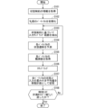
- FIG. 6 is a flowchart showing the particle filter calculation process executed by the target trajectory generating unit 321 in the motion planning apparatus 300 according to this embodiment.
- the target trajectory generation unit 321 first obtains information on state constraints that should be considered in advance (step S101). It then approximates the probability density distribution so that the state constraints are satisfied for each particle.
- the target trajectory generating unit 321 initializes Np particles (step S102).
- Np is an integer equal to or greater than 2.
- the Np particles can each have a different state quantity.
- the particles can be initialized based on the current state quantity of the moving body 1.
- the initialization of the particles is a process for preparing Np particles on software, and is a preparatory step required for executing the processes in and after step S102.
- the state quantity P of a particle is defined by the following equation (1):
- the state quantity of the n-th particle is represented as Pn .
- a weight w is defined for each particle, and the initial value is the same for all particles and is set as shown in the following formula (5).
- Time t is also defined, and the initial value is set to 0.
- the target trajectory generation unit 321 extracts the input sampling range based on the state constraint h(x) ⁇ 0 that should be considered in advance (step S103).
- the inequality is specifically expressed as the following equation (8).
- ⁇ (h) ⁇ ⁇ h is used, where " ⁇ ⁇ " is a positive constant.
- Non-Patent Document 1 discloses a method for calculating the speed range in which a moving object will not collide with an obstacle, and more specifically, this is disclosed in Sections II.B and III.B of Non-Patent Document 1.
- equations (6) and (8) are expressed in continuous time, but they can also be expressed in discrete time using the defined discrete time width ⁇ t.
- the state quantity x+ after a discrete time width ⁇ t seconds is predicted by the above-mentioned mathematical model f of the system in the input sampling range in which the state constraint h(x) ⁇ 0 is considered in advance under the condition of mathematical formula (8). This makes it possible to predict the state of the particle taking the constraint into account.
- the state quantity Pn of particles generated in the input sampling range that satisfies the formula (8) satisfies the state constraint h(x) ⁇ 0. Therefore, all generated particles are valid, and the approximation accuracy of the probability density distribution can be guaranteed.
- the approximation accuracy of the probability density distribution is defined as the number of valid particles. Although the approximation accuracy of the probability density distribution decreases by the number of valid particles that is reduced from the initially prepared Np , since all generated particles are valid, the approximation accuracy can be guaranteed. Since the approximation accuracy of the probability density distribution is guaranteed, post-processing is not required, and efficiency is high.
- the target trajectory generation unit 321 predicts the state after a discrete time width ⁇ t seconds based on the state constraint (step S104).
- the particle state prediction uses the mathematical model of formula (2).
- particles are generated using random numbers in the input sampling range extracted in step S103, making it possible to generate particles based on the state constraint h(x) ⁇ 0.
- the state quantity P of the particle is updated using the predicted state quantity x + and the input u which is the input sampling value, and is expressed as the following formula (9).
- the particle state quantity x, the predicted state quantity x + , and the input u which is the input sampling value are all column vectors, and transposition is used for simplification.
- the observation value of each particle is obtained (step S105).
- the observation variables are designed based on the goal of the motion plan.
- the goal of the motion plan is determined by the surrounding environment of the moving body 1 or the user's setting.
- the goals are to maintain an ideal movement path, to maintain a movement speed, and to maintain a distance from an obstacle.
- ⁇ is expressed as the following equation (10) as an observation variable for the lateral deviation y d from the ideal movement path, the movement speed v, and the distance d from an obstacle.
- observation variable can also be considered as a function ⁇ (x) of the state quantity x. In the following discussion, it is written as ⁇ for simplicity of notation.
- the observation variables include at least one of the lateral deviation y d from the ideal movement path, the movement speed v, and the distance d from the obstacle.
- the weight w of each particle is updated based on the difference between the observed value ⁇ of each particle and the ideal observed value ⁇ i .
- the ideal observed value ⁇ i is an observed value for the moving body 1 in a virtually designed ideal state, and is determined based on the target of the travel plan. Therefore, when the moving body 1 satisfies the target of the operation plan, the moving body 1 is in the ideal state.
- the ideal observed value ⁇ i is expressed by the following formula (11).
- each value corresponds to the observation variable ⁇ . Therefore, in this embodiment, the ideal state is that the lateral deviation is 0, the ideal moving speed is v i , and the distance d from the obstacle is kept large, that is, d approaches infinity ( ⁇ ) so that the value expressed by the natural logarithm e in formula (10) approaches 0.
- the weight w of each particle is updated based on the theory of particle filters.
- the weight w is proportional to the weight wn of the n-th particle and the likelihood ⁇ , as shown in the following formula (12), so that the integrated value of the weights of all particles becomes 1.
- the likelihood ⁇ of each particle is calculated using the following formula (13) using the covariance matrix Q of the particle's state quantity x and the covariance matrix R of the observation value ⁇ , which are set in advance.
- the det operator represents the calculation of the determinant of a square matrix
- the matrix S is expressed by the following formula (14).
- the matrix H is the differential coefficient obtained by differentiating the observation variable ⁇ with respect to the state quantity x when the state quantity x has a certain value (bar x), and is defined by the following formula (15).
- the target trajectory generating unit 321 resamples the particles based on the weight w of each particle (step S106).
- resampling is performed only when the virtual effective particle number Neff is equal to or less than the threshold value Nth , and otherwise, nothing is performed in this step.
- the virtual effective particle number Neff is calculated using the following formula (16). Note that resampling can also be performed every time.
- the reason we call it the "virtual effective particle number” is because the number of particles is calculated virtually using the weight of each particle, and when the weights of each particle are equal, the calculation result of formula (16) will match the number of particles.
- the resampling method is the same as for normal particle filters, where samples are taken at equal intervals from the empirical distribution function.
- the weights of each particle are initialized as equal based on formula (5).
- the target trajectory generating unit 321 calculates a weighted average value based on the weight w for the particle state quantity P obtained in the above process, stores the state quantity x and the input u in the target trajectory generating unit 321 as an operation plan (step S107), and updates the time to t + ⁇ t.
- the target trajectory generating unit 321 judges whether the updated time t has reached the planning horizon value ⁇ h , which is the planning target period of the motion plan (step S108). If t ⁇ ⁇ h (No), the process repeats the process from step S103 onward. On the other hand, if t ⁇ ⁇ h (Yes), the data of the state quantity x and the input u stored as the motion plan are output as the target trajectory and the target input data, and the calculation for generating the motion plan is terminated.
- N p 10 here, but in practice, sampling is performed with a rough guide of 10 times the number of states to be estimated.
- the initial values of all particles to be estimated refer to node 330, and in this embodiment, the calculation starts with the same value as node 330.
- the state transitions of these particles are predicted through the process described using equations (1) to (8), and the state quantities of the particles are updated using equation (9) to obtain updated values of the particles.
- These have a variation, for example, as shown by particle 331 when node 330 in FIG. 7 is set as the initial value, so as to satisfy the state constraint h(x) ⁇ 0 expressed in equation (3) while following equation (2) of the mathematical model.
- the weights are calculated according to the relationship between the target trajectory and the target input and the surrounding environment through the process described using equations (10) to (16), and resampling according to the weights is performed, resulting in, for example, a new node 332.
- information on the ideal path 400 and the obstacle 600 (or person 500) is acquired to calculate the observed value of equation (10).
- a particle filter has been described as an example of a sampling method, but the sampling method can also be a different method that has a technical background in the Monte Carlo method, for example.
- a feature of the present disclosure is that the input sampling range is restricted in advance based on state constraints expressed in a mathematical model, and can be introduced regardless of the form of the sampling method itself.
- state constraints are limited to those that take into account collision avoidance with obstacles, but are not limited to this.
- State constraints include constraints that take into account lane departures, constraints that take into account entry into dangerous areas, constraints that take into account rollovers due to sudden steering, constraints that take into account the range of motion in the case of a robot arm, and constraints that take into account singular postures.
- the input term appears as the first-order time derivative of the function h(x) representing the state constraint, but second-order or higher time derivatives can also be used.
- the state quantity x of the moving body 1 is defined as the position and velocity in the XY coordinate system, and the input u is redefined as the acceleration in the XY coordinate system as shown in the following equation (17).
- the mathematical model f of moving body 1 is also redefined as shown in the following mathematical formula (18).
- the state constraint h(x) ⁇ 0 is intended to prevent collision with an obstacle, as in the first embodiment, and is expressed as in formula (3).
- K b [k b1 , k b2 ] represents a vector in which all elements are positive.
- Non-Patent Document 2 discloses a method of calculating the acceleration range in which a moving body does not collide with an obstacle, and more specifically, this is disclosed in Section III of Non-Patent Document 2.
- the input sampling range is restricted by obtaining an input value based on a random number from the input sampling range restricted by formula (7).
- this restriction method it is also possible to first obtain an input value based on a random number in an unrestricted input sampling range, and then modify the input value so that it satisfies the constraint condition of formula (7).
- a modification method based on an optimization problem in which the input modification amount is an evaluation function can be used as a modification method.
- the input values when input values are obtained based on random numbers in the original input sampling range 804, which is an unrestricted input sampling range, the input values can be divided into, for example, input value 801 that satisfies formula (7) and input value 802 that does not satisfy formula (7), i.e., violates formula (7), based on boundary 806 where the sign of the left side of formula (7) changes.
- a correction amount 805 is introduced for each of the violating input values 802, and the corrected input values 803 are obtained so as to satisfy the original input sampling range 804 and the input sampling range restricted by formula (7). Then, the processing from step S104 onwards shown in FIG. 6 is executed using the input values 801 and the corrected input values 803.
- the input sampling range by limiting the input sampling range, if it is difficult to obtain an input value based on a random number from the range limited by formula (7), for example, the input value can be obtained based on a random number using a different optimization problem and then corrected.
- the designer can design the input sampling range to the range desired by the designer, and the amount of correction to the input value can be directly evaluated.
- the evaluation function can be set, for example, as the square of the input correction amount.
- formula (7) is linear with respect to the input, an analytical solution to the quadratic programming problem can be applied, improving calculation efficiency.
- the input sampling range restriction described in embodiment 1 or embodiment 3 requires that all input values obtained based on random numbers satisfy formula (7), but in embodiment 4, by adjusting the input sampling range in advance based on information about the state constraint h(x), it is also acceptable for some or all of the input values obtained based on random numbers not to satisfy formula (7).
- the input sampling range is approximately restricted by the probability density distribution function and the range is adjusted so that the number of input values that satisfy formula (7) is equal to or greater than a certain number.
- the range adjustment using the Gaussian distribution can be adjusted mechanically by adjusting it based on an optimization problem.
- the input sampling range is limited to a Gaussian distribution, and an example of the limiting method is shown in FIG. 9.
- the first embodiment is shown as an example.
- the input values obtained based on random numbers from a Gaussian distribution characterized by these modified mean value 815 and modified standard deviation 816 contain more values that satisfy formula (7) than input values obtained from the original input sampling range.
- These input sampling values are used to execute the processing from step S104 onwards in FIG. 6. For example, if the mean value 811 is modified by the modification amount 813 to obtain the modified mean value 815, the probability that the input values obtained based on random numbers will satisfy formula (7) can be adjusted to 0.5 or more.
- Each component of the motion planning apparatus 300 according to the first to fourth embodiments described above can be configured using a computer, and is realized by the computer executing a program. That is, for example, it is realized by a processing circuit 1000 shown in FIG. 10.
- a processor such as a CPU (Central Processing Unit) or a DSP (Digital Signal Processor) is applied to the processing circuit 1000, and the function of each part is realized by executing a program stored in a storage device.
- the target trajectory storage unit 322 is realized by a storage device included in the computer.
- Dedicated hardware may be applied to the processing circuit 1000.
- the processing circuit 1000 may be, for example, a single circuit, a composite circuit, a programmed processor, a parallel programmed processor, an ASIC (Application Specific Integrated Circuit), an FPGA (Field-Programmable Gate Array), or a combination of these.
- ASIC Application Specific Integrated Circuit
- FPGA Field-Programmable Gate Array
- memory 1002 can be, for example, a non-volatile or volatile semiconductor memory such as RAM, ROM, flash memory, EPROM (Erasable Programmable Read Only Memory), EEPROM (Electrically Erasable Programmable Read Only Memory), HDD (Hard Disk Drive), magnetic disk, flexible disk, optical disk, compact disk, mini disk, DVD (Digital Versatile Disc) and its drive device, or any other storage medium that will be used in the future.
- RAM random access memory
- ROM read only memory
- flash memory Erasable Programmable Read Only Memory
- EPROM Erasable Programmable Read Only Memory
- EEPROM Electrically Erasable Programmable Read Only Memory
- HDD Hard Disk Drive
- magnetic disk flexible disk
- optical disk compact disk
- mini disk mini disk
- DVD Digital Versatile Disc
- each component of the motion planning device 300 are realized by either hardware or software, etc.
- this is not limited to the above, and some of the components of the motion planning device 300 can be realized by dedicated hardware, and other components can be realized by software, etc.
- the functions of some components can be realized by the processing circuit 1000 as dedicated hardware, and for the functions of other components to be realized by the processing circuit 1000 as the processor 1001 reading and executing a program stored in the memory 1002.
- the motion planning device 300 can realize each of the above-mentioned functions through hardware, software, etc., or a combination of these.
Landscapes
- Engineering & Computer Science (AREA)
- Aviation & Aerospace Engineering (AREA)
- Radar, Positioning & Navigation (AREA)
- Remote Sensing (AREA)
- Physics & Mathematics (AREA)
- General Physics & Mathematics (AREA)
- Automation & Control Theory (AREA)
- Robotics (AREA)
- Mechanical Engineering (AREA)
- Control Of Position, Course, Altitude, Or Attitude Of Moving Bodies (AREA)
Abstract
La présente divulgation concerne un dispositif de planification de fonctionnement qui est destiné à un système dynamique et qui utilise un procédé d'échantillonnage, le dispositif de planification de fonctionnement comprenant : une unité de planification d'action qui délivre une contrainte d'état devant être prise en compte à l'avance pour le système dynamique et un modèle d'expression mathématique exprimant un mouvement du système dynamique, sur la base d'une cible à atteindre par le système dynamique ; et une unité de génération de plan de fonctionnement qui limite, sur la base du modèle d'expression mathématique et de la contrainte d'état, une plage d'échantillonnage d'entrée, et génère un plan de fonctionnement pour le système dynamique en réalisant un calcul d'estimation d'état, sur la base du modèle d'expression mathématique, dans la plage d'échantillonnage d'entrée.
Priority Applications (3)
| Application Number | Priority Date | Filing Date | Title |
|---|---|---|---|
| JP2023568059A JP7475562B1 (ja) | 2023-08-22 | 2023-08-22 | 動作計画装置 |
| CN202380101331.1A CN121773385A (zh) | 2023-08-22 | 2023-08-22 | 动作计划装置 |
| PCT/JP2023/030165 WO2025041268A1 (fr) | 2023-08-22 | 2023-08-22 | Dispositif de planification de fonctionnement |
Applications Claiming Priority (1)
| Application Number | Priority Date | Filing Date | Title |
|---|---|---|---|
| PCT/JP2023/030165 WO2025041268A1 (fr) | 2023-08-22 | 2023-08-22 | Dispositif de planification de fonctionnement |
Publications (1)
| Publication Number | Publication Date |
|---|---|
| WO2025041268A1 true WO2025041268A1 (fr) | 2025-02-27 |
Family
ID=90789779
Family Applications (1)
| Application Number | Title | Priority Date | Filing Date |
|---|---|---|---|
| PCT/JP2023/030165 Pending WO2025041268A1 (fr) | 2023-08-22 | 2023-08-22 | Dispositif de planification de fonctionnement |
Country Status (3)
| Country | Link |
|---|---|
| JP (1) | JP7475562B1 (fr) |
| CN (1) | CN121773385A (fr) |
| WO (1) | WO2025041268A1 (fr) |
Citations (6)
| Publication number | Priority date | Publication date | Assignee | Title |
|---|---|---|---|---|
| WO2011152140A1 (fr) * | 2010-05-31 | 2011-12-08 | オリンパスメディカルシステムズ株式会社 | Dispositif de détection de forme d'endoscope et procédé pour détecter la forme de la partie insérée d'un endoscope |
| JP2015197417A (ja) * | 2014-04-03 | 2015-11-09 | 日本電信電話株式会社 | 位置推定装置、方法、及びプログラム |
| JP2018534205A (ja) * | 2016-02-11 | 2018-11-22 | 三菱電機株式会社 | 車両の運動を制御する方法、及び車両の制御システム |
| KR20200048918A (ko) * | 2018-10-31 | 2020-05-08 | 삼성에스디에스 주식회사 | 측위 방법 및 그 장치 |
| WO2020129208A1 (fr) * | 2018-12-20 | 2020-06-25 | 三菱電機株式会社 | Dispositif de génération de plan de déplacement et système de conduite autonome |
| WO2022249218A1 (fr) * | 2021-05-24 | 2022-12-01 | 三菱電機株式会社 | Dispositif de planification de trajectoire |
Family Cites Families (1)
| Publication number | Priority date | Publication date | Assignee | Title |
|---|---|---|---|---|
| JP6232183B2 (ja) * | 2012-12-07 | 2017-11-15 | 株式会社日立アドバンストシステムズ | 移動端末装置及び測位システム |
-
2023
- 2023-08-22 CN CN202380101331.1A patent/CN121773385A/zh active Pending
- 2023-08-22 JP JP2023568059A patent/JP7475562B1/ja active Active
- 2023-08-22 WO PCT/JP2023/030165 patent/WO2025041268A1/fr active Pending
Patent Citations (6)
| Publication number | Priority date | Publication date | Assignee | Title |
|---|---|---|---|---|
| WO2011152140A1 (fr) * | 2010-05-31 | 2011-12-08 | オリンパスメディカルシステムズ株式会社 | Dispositif de détection de forme d'endoscope et procédé pour détecter la forme de la partie insérée d'un endoscope |
| JP2015197417A (ja) * | 2014-04-03 | 2015-11-09 | 日本電信電話株式会社 | 位置推定装置、方法、及びプログラム |
| JP2018534205A (ja) * | 2016-02-11 | 2018-11-22 | 三菱電機株式会社 | 車両の運動を制御する方法、及び車両の制御システム |
| KR20200048918A (ko) * | 2018-10-31 | 2020-05-08 | 삼성에스디에스 주식회사 | 측위 방법 및 그 장치 |
| WO2020129208A1 (fr) * | 2018-12-20 | 2020-06-25 | 三菱電機株式会社 | Dispositif de génération de plan de déplacement et système de conduite autonome |
| WO2022249218A1 (fr) * | 2021-05-24 | 2022-12-01 | 三菱電機株式会社 | Dispositif de planification de trajectoire |
Also Published As
| Publication number | Publication date |
|---|---|
| JPWO2025041268A1 (fr) | 2025-02-27 |
| JP7475562B1 (ja) | 2024-04-26 |
| CN121773385A (zh) | 2026-03-31 |
Similar Documents
| Publication | Publication Date | Title |
|---|---|---|
| US11698625B2 (en) | Stochastic model-predictive control of uncertain system | |
| EP4091028B1 (fr) | Commande adaptative de véhicule autonome ou semi-autonome | |
| Min et al. | RNN-based path prediction of obstacle vehicles with deep ensemble | |
| Bouton et al. | Scalable decision making with sensor occlusions for autonomous driving | |
| US11467591B2 (en) | Online agent using reinforcement learning to plan an open space trajectory for autonomous vehicles | |
| Akametalu et al. | Reachability-based safe learning with Gaussian processes | |
| JP7036545B2 (ja) | 能動的探索なしの強化学習に基づくオンライン学習法及び車両制御方法 | |
| US9568915B1 (en) | System and method for controlling autonomous or semi-autonomous vehicle | |
| US12078972B2 (en) | Model-based control with uncertain motion model | |
| US11409284B2 (en) | Relaxation optimization model to plan an open space trajectory for autonomous vehicles | |
| JP2022536263A (ja) | 動的障害物を有する環境における動作計画を容易にする装置、方法及び物品 | |
| CN114894206A (zh) | 路径规划方法及装置、车辆、存储介质 | |
| Berntorp et al. | Control architecture design for autonomous vehicles | |
| EP2280241A2 (fr) | Commande de véhicule | |
| JPWO2020129208A1 (ja) | 走行計画生成装置および自動運転システム | |
| Quirynen et al. | Integrated obstacle detection and avoidance in motion planning and predictive control of autonomous vehicles | |
| Singletary et al. | Safety-critical rapid aerial exploration of unknown environments | |
| WO2022094137A1 (fr) | Robot résistant aux collisions et véhicule aérien | |
| EP4564120A1 (fr) | Système de planification de mouvement incorporant des fonctions de contrainte pour un robot mobile et procédés mis en uvre par ordinateur associés | |
| KR20220107344A (ko) | 장애물에 의한 이동 로봇의 제어 시스템 및 그 제어 방법 | |
| Philippe et al. | Safe and online mpc for managing safety and comfort of autonomous vehicles in urban environment | |
| Berntorp et al. | Motion planning of autonomous road vehicles by particle filtering: Implementation and validation | |
| CN118011832A (zh) | 一种基于激光点云和障碍函数的运动体鲁棒安全控制方法 | |
| JP2022181105A (ja) | 移動体、制御装置及びそのプログラム | |
| Goswami et al. | Stochastic models for autonomous systems and robotics |
Legal Events
| Date | Code | Title | Description |
|---|---|---|---|
| ENP | Entry into the national phase |
Ref document number: 2023568059 Country of ref document: JP Kind code of ref document: A |
|
| WWE | Wipo information: entry into national phase |
Ref document number: 2023568059 Country of ref document: JP |
|
| NENP | Non-entry into the national phase |
Ref country code: DE |