WO2025041268A1 - 動作計画装置 - Google Patents
動作計画装置 Download PDFInfo
- Publication number
- WO2025041268A1 WO2025041268A1 PCT/JP2023/030165 JP2023030165W WO2025041268A1 WO 2025041268 A1 WO2025041268 A1 WO 2025041268A1 JP 2023030165 W JP2023030165 W JP 2023030165W WO 2025041268 A1 WO2025041268 A1 WO 2025041268A1
- Authority
- WO
- WIPO (PCT)
- Prior art keywords
- input
- motion planning
- motion
- state
- input sampling
- Prior art date
- Legal status (The legal status is an assumption and is not a legal conclusion. Google has not performed a legal analysis and makes no representation as to the accuracy of the status listed.)
- Pending
Links
Images


Classifications
-
- B—PERFORMING OPERATIONS; TRANSPORTING
- B25—HAND TOOLS; PORTABLE POWER-DRIVEN TOOLS; MANIPULATORS
- B25J—MANIPULATORS; CHAMBERS PROVIDED WITH MANIPULATION DEVICES
- B25J9/00—Program-controlled manipulators
- B25J9/10—Program-controlled manipulators characterised by positioning means for manipulator elements
-
- G—PHYSICS
- G05—CONTROLLING; REGULATING
- G05D—SYSTEMS FOR CONTROLLING OR REGULATING NON-ELECTRIC VARIABLES
- G05D1/00—Control of position, course, altitude or attitude of land, water, air or space vehicles, e.g. using automatic pilots
- G05D1/60—Intended control result
- G05D1/617—Safety or protection, e.g. defining protection zones around obstacles or avoiding hazards
- G05D1/622—Obstacle avoidance
Definitions
- This disclosure relates to a motion planning device, and in particular to a motion planning device for dynamic systems using a sampling method.
- Motion planning problems involve constraints that the target must satisfy, but the sampling method has the advantage of being able to easily handle complex constraints, as it creates a motion plan after determining for each particle whether it is a valid particle that satisfies the constraints (valid particles) or an invalid particle that does not (invalid particles).
- the control input is sampled, then the time evolution of the physical model is calculated, and valid particles are determined for the state constraints, so that the vehicle is controlled so as to optimize the probability of achieving the desired motion using only valid particles.
- the autonomous driving system of Patent Document 2 samples the control input within the constraints of road surface slippage, thereby controlling the vehicle to optimize the probability of achieving the desired motion using only effective particles for the road surface slippage.
- Sampling methods require a large amount of sampling calculations to guarantee the approximation accuracy of the probability density distribution that is approximated based on sampling.
- the time evolution of a physical model after performing input sampling as in Patent Document 1 and determining effective particles that satisfy constraints, if the number of effective particles is small, the approximation accuracy of the probability density distribution cannot be guaranteed. In other words, a decrease in effective particles increases the possibility of a decrease in the functionality of the method.
- Patent Document 2 limits the input sampling in advance, making it easy to ensure a valid number of particles, but since it is limited to road surface slippage, it is difficult to apply it to other applications, and when other state constraints are taken into account, the results are similar to those of Patent Document 1.
- the present disclosure has been made to solve the problems described above, and aims to provide a motion planning device that uses a sampling method that is unlikely to cause a degradation in the functionality of the method due to a decrease in effective particles, and that does not limit the state constraints that must be considered in advance in the system to which it is applied.
- the motion planning device is a motion planning device for a dynamic system using a sampling method, and includes: an action planning unit that outputs a mathematical model that expresses the motion of the dynamic system based on a goal to be achieved by the dynamic system and state constraints of the dynamic system that should be considered in advance; and a motion plan generating unit that restricts an input sampling range based on the mathematical model and the state constraints, and generates a motion plan for the dynamic system by performing a state estimation calculation within the input sampling range based on the mathematical model.
- the motion planning device disclosed herein performs input sampling within the range of state constraints that should be considered in advance, improving the approximation accuracy of the probability density distribution that is approximated based on the sampling, reducing the possibility of the method's functionality deteriorating due to a decrease in effective particles, and not limiting the state constraints that should be considered in advance in the system to which it is applied.
- FIG. 1 is a schematic diagram illustrating a configuration of a moving body equipped with a motion planning device according to a first embodiment of the present disclosure.
- 1 is a schematic diagram illustrating a configuration of a moving body equipped with a motion planning device according to a first embodiment of the present disclosure.
- FIG. 1 is a diagram illustrating an example of a situation in which a moving object equipped with the motion planning device according to the first embodiment of the present disclosure moves.
- 1 is a block diagram showing a configuration of a motion planning device according to a first embodiment of the present disclosure.
- FIG. 2 is a diagram illustrating a coordinate system used in the first embodiment according to the present disclosure.
- 5 is a flowchart showing a calculation process of a particle filter used in the motion planning device according to the first embodiment of the present disclosure.
- FIG. 1 is a diagram illustrating a schematic diagram of a result of generating a motion plan in the motion planning device according to the first embodiment of the present disclosure.
- FIG. FIG. 13 is a diagram illustrating a method of correcting input sampling values in a motion planning device according to a third embodiment of the present disclosure.
- FIG. 13 is a diagram illustrating a method for limiting an input sampling range in a motion planning device according to a fourth embodiment of the present disclosure.
- FIG. 2 is a diagram illustrating a hardware configuration for implementing the motion planning device according to the first to fourth embodiments.
- FIG. 2 is a diagram illustrating a hardware configuration for implementing the motion planning device according to the first to fourth embodiments.
- FIG. 1 and 2 are schematic diagrams showing a system configuration of a moving body 1, which is a dynamic system equipped with a motion planning device according to a first embodiment of the present disclosure.
- FIG. 1 is a perspective view of the moving body 1 as viewed from above, and
- FIG. 2 is a side view of the moving body 1.
- the moving body 1 includes wheels 101, actuators 102, and a battery 103 as driving devices.
- the actuators 102 convert power obtained from the battery 103 into driving force and input the power to the wheels 101.
- the actuators 102 are controlled by a control device 10.
- the control device 10 includes a storage unit and a calculation unit, and controls the actuators 102 according to a set control program to control the movement of the moving body 1.
- a differential two-wheel mobile body is a mobile body that has two wheels that can rotate independently and uses the difference in rotational speed between each wheel to move straight and turn.
- dynamic systems to which this disclosure applies are not limited to moving bodies, but can be applied to any dynamic system in which the motion of a robot arm or overhead crane, for example, is expressed as a mathematical model (differential equation).
- the dynamic system is treated as a moving body, it is possible to set a complex target trajectory toward a target location.
- the moving body 1 is equipped with a wheel angle sensor 111 shown in FIG. 1, an optical range sensor 112 shown in FIG. 2, and a depth camera 113 as observation devices.
- the observation devices are connected to the control device 10.
- the wheel angle sensor 111 is provided on each wheel 101 and detects the amount of rotation of the wheel 101.
- the control device 10 calculates the amount of movement of the mobile object 1 based on the amount of rotation of the wheel 101.
- the wheel angle sensor 111 is, for example, configured by a rotary encoder.
- the optical range sensor 112 is, for example, a LiDAR (Light Detection and Ranging) and is provided on the top surface of the mobile object 1.
- the optical range sensor 112 measures physical shape data of the space in the surrounding environment of the mobile object 1 along a scanning plane. Based on the measured shape data, the control device 10 creates a map of the surrounding environment. By referring to the created map, it is possible to estimate where the mobile object 1 is located on the map plane. At this time, it is also possible to create a map in advance and estimate the position of the mobile object 1 by referring to the map information.
- FIG. 3 is a diagram showing a schematic example of a situation in which the moving body 1 moves.
- the physical shape data of the space obtained by the optical range sensor 112 includes the shapes of a person 500 and an object 600 that are obstacles to the movement of the moving body 1.
- the control device 10 recognizes this shape data as objects that the moving body 1 should avoid.
- all objects that impede the movement of the moving body 1, such as people, walls, and other moving bodies, are referred to as obstacles.
- the forward depth camera 113 acquires physical shape data of the space in front of the vehicle along with an image.
- the forward depth camera 113 acquires range information within the camera's angle of view, and the optical range sensor 112 supplements the shape data on the scanning plane (data cut from a plane in three-dimensional space).
- the motion planning device 300 shown in FIG. 4 is included in the control device 10, and has a behavior planning unit 310 and a motion plan generating unit 320.
- the control device 10 is a device that controls the moving body 1 according to a target trajectory, and is installed, for example, as an embedded computer.
- the action planning unit 310 has a moving object state estimation unit 311, a moving target calculation unit 312, and a state constraint calculation unit 313.
- the mobile object state estimation unit 311 performs self-position estimation of the mobile object 1 based on information from, for example, a global positioning sensor (GPS).
- GPS global positioning sensor
- the self-position information estimated by the mobile object state estimation unit 311 is output to the motion plan generation unit 320 and the movement target calculation unit 312.
- the moving target calculation unit 312 calculates the goal to be achieved by the moving body 1 based on the self-position of the moving body 1 output from the moving body state estimation unit 311 and the obstacle information output from the observation device 200, and outputs the goal to the state constraint calculation unit 313.
- the goal is, for example, a reference trajectory and a target point, information on obstacles to be avoided, etc.
- the state constraint calculation unit 313 in the action planning unit 310 calculates and outputs a mathematical model of the moving body 1 and state constraint information that should be considered in advance based on the goal that the moving body 1 is to achieve, which is output from the movement target calculation unit 312.
- the state constraint information that should be considered in advance is relative position information between the moving body 1 and an obstacle, and is output based on information including the position of the moving body 1, the obstacle position, and the obstacle shape.
- the relative position information output from the state constraint calculation unit 313 is input to the operation plan generation unit 320.
- the relative distance between the moving body 1 and the surrounding environment can be obtained from the optical range sensor 112 of the observation device 200.
- the relative distance is not limited to information obtained directly from the sensor, but can be a value calculated based on values from one or more sensors.
- the positions of the system to be controlled and the object to be avoided can be obtained from a GPS, and the relative distance can be calculated from each position.
- two camera image sensors can be used to obtain image data for each, and the relative distance can be calculated using the parallax in the image data for each.
- the value can be calculated only by software based on values that have been mathematically formulated without using sensors. For example, even if a person or robot is not detected, a process can be performed that constantly predicts a person or robot jumping out using a formula. This is a process that uses simulation to place virtual walls that indicate undetected people jumping out or areas where moving objects are prohibited from entering, or predictive calculations that assume obstacles will appear probabilistically from outside the sensor range.
- the motion plan generating unit 320 has a target trajectory generating unit 321 and a target trajectory storage unit 322.
- the target trajectory generating unit 321 generates a target trajectory for moving while achieving a goal, taking into consideration avoiding obstacles in advance, based on relative position information between the moving body 1 and obstacles, such as relative distance, output from the action planning unit 310. A sampling method is applied to generate this target trajectory.
- the generated target trajectory is output to the target trajectory storage unit 322.
- the target trajectory memory unit 322 stores the target trajectory obtained from the target trajectory generation unit 321, selects the necessary target trajectory information, and outputs it to the driving device 100 as an operation plan.
- the driving device 100 operates the moving body 1 according to the received operation plan.
- FIG. 5 is a diagram showing a schematic diagram of a coordinate system used in the first embodiment.
- the X-axis and Y-axis in FIG. 5 are inertial coordinate systems, and xr and yr represent the center of gravity of the moving body 1 in the inertial coordinate system.
- xr and yr are not limited to the center of gravity as long as they can represent the position of the moving body 1, and can be, for example, the shape center point, the depth camera installation point, and the range sensor installation point.
- vx and vy are the X-direction and Y-direction velocities of the moving body 1 in the inertial coordinate system.
- xo and yo are the representative point positions of the obstacle 600, and are also expressed in the XY inertial coordinate system.
- the representative point position of the obstacle 600 can be one or more points, and can be, for example, the point that is the shortest distance between the moving body 1 and the obstacle 600, the shape center of the obstacle 600, and the center of gravity of the obstacle 600.
- the target trajectory generating unit 321 generates a target trajectory, which is an index for the control device 10 to control the moving body 1, as a motion plan by a sampling method based on information obtained from the observation device 200.
- the motion planning device 300 of the first embodiment performs a time evolution calculation of the state using a mathematical model f that mathematically represents the motion of the moving body 1, and generates a target trajectory by solving a designed optimization problem after taking into account state constraints in advance.
- a particle filter which is a type of sampling method, is used.
- the effect of the present disclosure applies to all cases in which calculations related to the time evolution of a dynamic system are included in the formulation of the sampling method, so the sampling method is not limited to the particle filter. Details of this effect will be described in the specific formulation described later.
- the state quantity x of the moving body and the input u used in the target trajectory generating unit 321 are set as shown in the following formula (1).
- v_x is the velocity in the X direction
- v_y is the velocity in the Y direction.
- the mathematical model f that represents the motion of a moving object is expressed by the following mathematical formula (2) and is linear with respect to the input. This simplifies the extraction of the input sampling range and reduces the computational load.
- formulas (1) and (2) are just examples of mathematical models, so the state quantity x, input u, and mathematical model f can be selected according to the characteristics of the system.
- the coordinate system is not limited to the Cartesian coordinate system, and can be defined, for example, in a path coordinate system.
- the state constraint that must be considered in advance is the state constraint h(x) ⁇ 0, which specifies that the moving body 1 will not collide with an obstacle, and is expressed as the following equation (3).
- r m is a value that represents a certain distance from an obstacle. This means that while the state constraint h(x) ⁇ 0 is satisfied, the robot moves while maintaining a distance of r m or more from the obstacle.
- This state constraint h(x) ⁇ 0 can also be considered as h(x) ⁇ 0. However, since this embodiment is concerned with the state constraint h(x) ⁇ 0, attention should be paid to the positive and negative signs.
- state constraint h(x) is a scalar value
- the extraction of the input sampling range can be simplified and the computational load can be reduced.
- the positions x o and y o of the obstacle may be included in the mathematical model, and the positions x o and y o of the obstacle may be defined as a dynamic system.
- J(x, u) is the evaluation function.
- the evaluation function can be designed according to the desired evaluation value. For example, the time integral value of the distance to the target point or the time integral value of the magnitude of the input can be used.
- Equation (4) expresses the optimization that minimizes the time integral of the distance to the target point and the time integral of the magnitude of the input. Note that the term "evaluation function" is used as a term in optimization theory in the field of mathematics.
- the formulation has been described for a mobile body that can move in all directions, but the formulation is not limited to this as long as the mathematical model f of the dynamic system and the state constraint h(x) can be expressed.
- a differential two-wheel model or a four-wheel vehicle model can also be used.
- a particle filter is used as a sampling method.
- the particle filter is a method for predicting time-series data using a probability density distribution. By executing a state estimation calculation using this particle filter, the optimization problem of Equation (4) is solved sequentially.
- Particle filters as a state estimation calculation, use multiple particles to approximate the probability density distribution of a state; for example, if there are many particles that indicate a certain state quantity, the probability density of that state is high. In this case, a large number of particles are required to ensure the accuracy of the approximation of the probability density distribution.
- a decrease in effective particles causes a degradation of the method's functionality. This degradation occurs when a particle calculated within an algorithm is deleted in violation of a constraint.
- the technology related to this disclosure maintains the number of effective particles and suppresses degradation of functionality by taking into account in advance the constraints that cause this degradation.
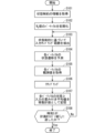
- FIG. 6 is a flowchart showing the particle filter calculation process executed by the target trajectory generating unit 321 in the motion planning apparatus 300 according to this embodiment.
- the target trajectory generation unit 321 first obtains information on state constraints that should be considered in advance (step S101). It then approximates the probability density distribution so that the state constraints are satisfied for each particle.
- the target trajectory generating unit 321 initializes Np particles (step S102).
- Np is an integer equal to or greater than 2.
- the Np particles can each have a different state quantity.
- the particles can be initialized based on the current state quantity of the moving body 1.
- the initialization of the particles is a process for preparing Np particles on software, and is a preparatory step required for executing the processes in and after step S102.
- the state quantity P of a particle is defined by the following equation (1):
- the state quantity of the n-th particle is represented as Pn .
- a weight w is defined for each particle, and the initial value is the same for all particles and is set as shown in the following formula (5).
- Time t is also defined, and the initial value is set to 0.
- the target trajectory generation unit 321 extracts the input sampling range based on the state constraint h(x) ⁇ 0 that should be considered in advance (step S103).
- the inequality is specifically expressed as the following equation (8).
- ⁇ (h) ⁇ ⁇ h is used, where " ⁇ ⁇ " is a positive constant.
- Non-Patent Document 1 discloses a method for calculating the speed range in which a moving object will not collide with an obstacle, and more specifically, this is disclosed in Sections II.B and III.B of Non-Patent Document 1.
- equations (6) and (8) are expressed in continuous time, but they can also be expressed in discrete time using the defined discrete time width ⁇ t.
- the state quantity x+ after a discrete time width ⁇ t seconds is predicted by the above-mentioned mathematical model f of the system in the input sampling range in which the state constraint h(x) ⁇ 0 is considered in advance under the condition of mathematical formula (8). This makes it possible to predict the state of the particle taking the constraint into account.
- the state quantity Pn of particles generated in the input sampling range that satisfies the formula (8) satisfies the state constraint h(x) ⁇ 0. Therefore, all generated particles are valid, and the approximation accuracy of the probability density distribution can be guaranteed.
- the approximation accuracy of the probability density distribution is defined as the number of valid particles. Although the approximation accuracy of the probability density distribution decreases by the number of valid particles that is reduced from the initially prepared Np , since all generated particles are valid, the approximation accuracy can be guaranteed. Since the approximation accuracy of the probability density distribution is guaranteed, post-processing is not required, and efficiency is high.
- the target trajectory generation unit 321 predicts the state after a discrete time width ⁇ t seconds based on the state constraint (step S104).
- the particle state prediction uses the mathematical model of formula (2).
- particles are generated using random numbers in the input sampling range extracted in step S103, making it possible to generate particles based on the state constraint h(x) ⁇ 0.
- the state quantity P of the particle is updated using the predicted state quantity x + and the input u which is the input sampling value, and is expressed as the following formula (9).
- the particle state quantity x, the predicted state quantity x + , and the input u which is the input sampling value are all column vectors, and transposition is used for simplification.
- the observation value of each particle is obtained (step S105).
- the observation variables are designed based on the goal of the motion plan.
- the goal of the motion plan is determined by the surrounding environment of the moving body 1 or the user's setting.
- the goals are to maintain an ideal movement path, to maintain a movement speed, and to maintain a distance from an obstacle.
- ⁇ is expressed as the following equation (10) as an observation variable for the lateral deviation y d from the ideal movement path, the movement speed v, and the distance d from an obstacle.
- observation variable can also be considered as a function ⁇ (x) of the state quantity x. In the following discussion, it is written as ⁇ for simplicity of notation.
- the observation variables include at least one of the lateral deviation y d from the ideal movement path, the movement speed v, and the distance d from the obstacle.
- the weight w of each particle is updated based on the difference between the observed value ⁇ of each particle and the ideal observed value ⁇ i .
- the ideal observed value ⁇ i is an observed value for the moving body 1 in a virtually designed ideal state, and is determined based on the target of the travel plan. Therefore, when the moving body 1 satisfies the target of the operation plan, the moving body 1 is in the ideal state.
- the ideal observed value ⁇ i is expressed by the following formula (11).
- each value corresponds to the observation variable ⁇ . Therefore, in this embodiment, the ideal state is that the lateral deviation is 0, the ideal moving speed is v i , and the distance d from the obstacle is kept large, that is, d approaches infinity ( ⁇ ) so that the value expressed by the natural logarithm e in formula (10) approaches 0.
- the weight w of each particle is updated based on the theory of particle filters.
- the weight w is proportional to the weight wn of the n-th particle and the likelihood ⁇ , as shown in the following formula (12), so that the integrated value of the weights of all particles becomes 1.
- the likelihood ⁇ of each particle is calculated using the following formula (13) using the covariance matrix Q of the particle's state quantity x and the covariance matrix R of the observation value ⁇ , which are set in advance.
- the det operator represents the calculation of the determinant of a square matrix
- the matrix S is expressed by the following formula (14).
- the matrix H is the differential coefficient obtained by differentiating the observation variable ⁇ with respect to the state quantity x when the state quantity x has a certain value (bar x), and is defined by the following formula (15).
- the target trajectory generating unit 321 resamples the particles based on the weight w of each particle (step S106).
- resampling is performed only when the virtual effective particle number Neff is equal to or less than the threshold value Nth , and otherwise, nothing is performed in this step.
- the virtual effective particle number Neff is calculated using the following formula (16). Note that resampling can also be performed every time.
- the reason we call it the "virtual effective particle number” is because the number of particles is calculated virtually using the weight of each particle, and when the weights of each particle are equal, the calculation result of formula (16) will match the number of particles.
- the resampling method is the same as for normal particle filters, where samples are taken at equal intervals from the empirical distribution function.
- the weights of each particle are initialized as equal based on formula (5).
- the target trajectory generating unit 321 calculates a weighted average value based on the weight w for the particle state quantity P obtained in the above process, stores the state quantity x and the input u in the target trajectory generating unit 321 as an operation plan (step S107), and updates the time to t + ⁇ t.
- the target trajectory generating unit 321 judges whether the updated time t has reached the planning horizon value ⁇ h , which is the planning target period of the motion plan (step S108). If t ⁇ ⁇ h (No), the process repeats the process from step S103 onward. On the other hand, if t ⁇ ⁇ h (Yes), the data of the state quantity x and the input u stored as the motion plan are output as the target trajectory and the target input data, and the calculation for generating the motion plan is terminated.
- N p 10 here, but in practice, sampling is performed with a rough guide of 10 times the number of states to be estimated.
- the initial values of all particles to be estimated refer to node 330, and in this embodiment, the calculation starts with the same value as node 330.
- the state transitions of these particles are predicted through the process described using equations (1) to (8), and the state quantities of the particles are updated using equation (9) to obtain updated values of the particles.
- These have a variation, for example, as shown by particle 331 when node 330 in FIG. 7 is set as the initial value, so as to satisfy the state constraint h(x) ⁇ 0 expressed in equation (3) while following equation (2) of the mathematical model.
- the weights are calculated according to the relationship between the target trajectory and the target input and the surrounding environment through the process described using equations (10) to (16), and resampling according to the weights is performed, resulting in, for example, a new node 332.
- information on the ideal path 400 and the obstacle 600 (or person 500) is acquired to calculate the observed value of equation (10).
- a particle filter has been described as an example of a sampling method, but the sampling method can also be a different method that has a technical background in the Monte Carlo method, for example.
- a feature of the present disclosure is that the input sampling range is restricted in advance based on state constraints expressed in a mathematical model, and can be introduced regardless of the form of the sampling method itself.
- state constraints are limited to those that take into account collision avoidance with obstacles, but are not limited to this.
- State constraints include constraints that take into account lane departures, constraints that take into account entry into dangerous areas, constraints that take into account rollovers due to sudden steering, constraints that take into account the range of motion in the case of a robot arm, and constraints that take into account singular postures.
- the input term appears as the first-order time derivative of the function h(x) representing the state constraint, but second-order or higher time derivatives can also be used.
- the state quantity x of the moving body 1 is defined as the position and velocity in the XY coordinate system, and the input u is redefined as the acceleration in the XY coordinate system as shown in the following equation (17).
- the mathematical model f of moving body 1 is also redefined as shown in the following mathematical formula (18).
- the state constraint h(x) ⁇ 0 is intended to prevent collision with an obstacle, as in the first embodiment, and is expressed as in formula (3).
- K b [k b1 , k b2 ] represents a vector in which all elements are positive.
- Non-Patent Document 2 discloses a method of calculating the acceleration range in which a moving body does not collide with an obstacle, and more specifically, this is disclosed in Section III of Non-Patent Document 2.
- the input sampling range is restricted by obtaining an input value based on a random number from the input sampling range restricted by formula (7).
- this restriction method it is also possible to first obtain an input value based on a random number in an unrestricted input sampling range, and then modify the input value so that it satisfies the constraint condition of formula (7).
- a modification method based on an optimization problem in which the input modification amount is an evaluation function can be used as a modification method.
- the input values when input values are obtained based on random numbers in the original input sampling range 804, which is an unrestricted input sampling range, the input values can be divided into, for example, input value 801 that satisfies formula (7) and input value 802 that does not satisfy formula (7), i.e., violates formula (7), based on boundary 806 where the sign of the left side of formula (7) changes.
- a correction amount 805 is introduced for each of the violating input values 802, and the corrected input values 803 are obtained so as to satisfy the original input sampling range 804 and the input sampling range restricted by formula (7). Then, the processing from step S104 onwards shown in FIG. 6 is executed using the input values 801 and the corrected input values 803.
- the input sampling range by limiting the input sampling range, if it is difficult to obtain an input value based on a random number from the range limited by formula (7), for example, the input value can be obtained based on a random number using a different optimization problem and then corrected.
- the designer can design the input sampling range to the range desired by the designer, and the amount of correction to the input value can be directly evaluated.
- the evaluation function can be set, for example, as the square of the input correction amount.
- formula (7) is linear with respect to the input, an analytical solution to the quadratic programming problem can be applied, improving calculation efficiency.
- the input sampling range restriction described in embodiment 1 or embodiment 3 requires that all input values obtained based on random numbers satisfy formula (7), but in embodiment 4, by adjusting the input sampling range in advance based on information about the state constraint h(x), it is also acceptable for some or all of the input values obtained based on random numbers not to satisfy formula (7).
- the input sampling range is approximately restricted by the probability density distribution function and the range is adjusted so that the number of input values that satisfy formula (7) is equal to or greater than a certain number.
- the range adjustment using the Gaussian distribution can be adjusted mechanically by adjusting it based on an optimization problem.
- the input sampling range is limited to a Gaussian distribution, and an example of the limiting method is shown in FIG. 9.
- the first embodiment is shown as an example.
- the input values obtained based on random numbers from a Gaussian distribution characterized by these modified mean value 815 and modified standard deviation 816 contain more values that satisfy formula (7) than input values obtained from the original input sampling range.
- These input sampling values are used to execute the processing from step S104 onwards in FIG. 6. For example, if the mean value 811 is modified by the modification amount 813 to obtain the modified mean value 815, the probability that the input values obtained based on random numbers will satisfy formula (7) can be adjusted to 0.5 or more.
- Each component of the motion planning apparatus 300 according to the first to fourth embodiments described above can be configured using a computer, and is realized by the computer executing a program. That is, for example, it is realized by a processing circuit 1000 shown in FIG. 10.
- a processor such as a CPU (Central Processing Unit) or a DSP (Digital Signal Processor) is applied to the processing circuit 1000, and the function of each part is realized by executing a program stored in a storage device.
- the target trajectory storage unit 322 is realized by a storage device included in the computer.
- Dedicated hardware may be applied to the processing circuit 1000.
- the processing circuit 1000 may be, for example, a single circuit, a composite circuit, a programmed processor, a parallel programmed processor, an ASIC (Application Specific Integrated Circuit), an FPGA (Field-Programmable Gate Array), or a combination of these.
- ASIC Application Specific Integrated Circuit
- FPGA Field-Programmable Gate Array
- memory 1002 can be, for example, a non-volatile or volatile semiconductor memory such as RAM, ROM, flash memory, EPROM (Erasable Programmable Read Only Memory), EEPROM (Electrically Erasable Programmable Read Only Memory), HDD (Hard Disk Drive), magnetic disk, flexible disk, optical disk, compact disk, mini disk, DVD (Digital Versatile Disc) and its drive device, or any other storage medium that will be used in the future.
- RAM random access memory
- ROM read only memory
- flash memory Erasable Programmable Read Only Memory
- EPROM Erasable Programmable Read Only Memory
- EEPROM Electrically Erasable Programmable Read Only Memory
- HDD Hard Disk Drive
- magnetic disk flexible disk
- optical disk compact disk
- mini disk mini disk
- DVD Digital Versatile Disc
- each component of the motion planning device 300 are realized by either hardware or software, etc.
- this is not limited to the above, and some of the components of the motion planning device 300 can be realized by dedicated hardware, and other components can be realized by software, etc.
- the functions of some components can be realized by the processing circuit 1000 as dedicated hardware, and for the functions of other components to be realized by the processing circuit 1000 as the processor 1001 reading and executing a program stored in the memory 1002.
- the motion planning device 300 can realize each of the above-mentioned functions through hardware, software, etc., or a combination of these.
Landscapes
- Engineering & Computer Science (AREA)
- Aviation & Aerospace Engineering (AREA)
- Radar, Positioning & Navigation (AREA)
- Remote Sensing (AREA)
- Physics & Mathematics (AREA)
- General Physics & Mathematics (AREA)
- Automation & Control Theory (AREA)
- Robotics (AREA)
- Mechanical Engineering (AREA)
- Control Of Position, Course, Altitude, Or Attitude Of Moving Bodies (AREA)
Abstract
本開示はサンプリング手法による動的システムの動作計画装置に関し、動的システムに達成させる目標に基づいて動的システムの運動を表現する数式モデルと動的システムの事前に考慮すべき状態制約を出力する行動計画部と、数式モデルと状態制約に基づいて入力サンプリング範囲を制限し、数式モデルに基づいて入力サンプリング範囲での状態推定演算により、動的システムの動作計画を生成する動作計画生成部と、を有している。
Description
本開示は動作計画装置に関し、特に、サンプリング手法による動的システムの動作計画装置に関する。
動的システムの動作計画問題においていくつかの手法が提案されており、そのうちの1つとしてサンプリング手法によるものが開発されている。動作計画問題においては対象が満たすべき制約が存在するが、サンプリング手法では各パーティクルにおいて制約を満たす有効なパーティクル(有効パーティクル)と制約を満たさない無効なパーティクル(無効パーティクル)を判定した上で動作計画を立てるため、複雑な制約にも対応しやすいという利点がある。
例えば、特許文献1の車両制御システムでは、制御入力のサンプリングを実施した後に物理モデルの時間発展を計算し、状態制約に対する有効パーティクルの判定を行うことで、有効パーティクルのみを用いて所望の運動を満たす確率が最適となるように車両を制御している。
また、特許文献2の自動運転システムでは、路面の滑りの制約の範囲内で制御入力のサンプリングを実施することで路面の滑りに対する有効パーティクルのみを用いて所望の運動を満たす確率が最適となるように車両を制御している。
A. D. Ames X. Xu, J. W. Grizzle and P. Tabuada. "Control barrier function based quadratic programs for safety critical systems." IEEE Transactions on Automatic Control, Vol. 62, No. 8, pp.3861-3876, 2016.
Q. Nguyen and K. Sreenath. "Exponential control barrier functions for enforcing high relative-degree safety-critical constraints." 2016 American Control Conference. 2016.
サンプリング手法では、サンプリングに基づいて近似される確率密度分布の近似精度を保証するために大量のサンプリング計算が必要である。特許文献1のように入力サンプリングを実施した後に物理モデルの時間発展を計算し、制約を満たす有効パーティクルを判定する場合、有効パーティクル数が少ないと確率密度分布の近似精度を保証できない。つまり、有効なパーティクルの減少によって手法の機能低下が生じる可能性が高くなる。
また、特許文献2の手法では、事前に入力サンプリングを制限しているため、有効パーティクル数を確保しやすいが、路面の滑りに限定されているため他の用途に適用することが難しく、他の状態制約を考慮する場合には特許文献1と同様の結果となる。
本開示は、上記のような問題点を解決するためになされたものであり、有効なパーティクルの減少によって手法の機能低下が生じる可能性が低く、適用先のシステムにおいて事前に考慮すべき状態制約が限定されないサンプリング手法による動作計画装置を提供することを目的とする。
本開示に係る動作計画装置は、サンプリング手法による動的システムの動作計画装置であって、前記動的システムに達成させる目標に基づいて前記動的システムの運動を表現する数式モデルと前記動的システムの事前に考慮すべき状態制約を出力する行動計画部と、前記数式モデルと前記状態制約に基づいて入力サンプリング範囲を制限し、前記数式モデルに基づいて前記入力サンプリング範囲での状態推定演算により、前記動的システムの動作計画を生成する動作計画生成部と、を有している。
本開示に係る動作計画装置によれば、事前に考慮すべき状態制約の範囲内で入力サンプリングを行うため、サンプリングに基づいて近似される確率密度分布の近似精度を向上させることができ有効なパーティクルの減少によって手法の機能低下が生じる可能性を低減でき、適用先のシステムにおいて事前に考慮すべき状態制約が限定されない。
<実施の形態1>
<移動体のシステム構成>
図1および図2は、本開示に係る実施の形態1の動作計画装置を搭載した動的システムである移動体1のシステム構成を示す概略図である。図1は移動体1を上面から見た透視図であり、図2は移動体1の側面図である。図1に示すように移動体1は、駆動装置として、車輪101、アクチュエータ102およびバッテリ103を備えている。アクチュエータ102はバッテリ103から得た電力を駆動力に変換し、車輪101へ入力する。アクチュエータ102は制御装置10によって制御される。制御装置10は、記憶部と演算部を備えており、設定された制御プログラムに従ってアクチュエータ102を制御し、移動体1の移動を制御する。
本実施の形態では、3つの車輪と3つのアクチュエータを使用し全方向に移動可能な移動体1に動作計画装置を搭載した例を示しているが、これに限定されず、例えば差動二輪移動体または脚式移動ロボットに搭載することもできる。ここで、差動二輪移動体とは、独立に回転可能な車輪を2つ有しており、各車輪の回転速度差を利用して直進および旋回を行う移動体である。
また、本開示の適用対象である動的システムは移動体に限らず、例えばロボットアームまたは天井クレーンなどの運動が数式モデル(微分方程式)として表される動的システムであれば適用可能である。
動的システムを移動体とした場合は、目標地点に向けて複雑な目標軌道を設定することが可能となる。
移動体1は、観測装置として、図1に示す車輪角度センサ111、図2に示す光学式測域センサ112および深度カメラ113を備えている。当該観測装置は制御装置10に接続されている。
車輪角度センサ111は各車輪101に設けられ、車輪101の回転量を検出する。車輪101の回転量に基づいて制御装置10により移動体1の移動量を算出する。車輪角度センサ111は、例えばロータリーエンコーダによって構成される。
光学式測域センサ112は、例えばLiDAR(Light Detection and Ranging)であり、移動体1の上面に備えられている。光学式測域センサ112は、移動体1の周辺環境における空間の物理的な形状データを走査平面に沿って計測する。計測された形状データに基づいて、制御装置10は周辺環境の地図を作成する。作成された地図を参照することで、移動体1が地図平面上のどの位置にいるのかを推定する。この際に、地図を予め作成し、その地図情報を参照することで移動体1の位置を推定することもできる。
図3は、移動体1が移動を行う状況の一例を模式的に示す図である。図3において、光学式測域センサ112で得られた空間の物理的な形状データは、移動体1の走行に対して障害となる人500および障害となる物600の形状を含む。制御装置10は、これら形状データを移動体1が避けるべき対象であると認知する。なお、以下の説明では、人、壁、別の移動体などの移動体1の移動を妨げる対象全てを障害物として表記する。
前方深度カメラ113は、車両前方の空間の物理的な形状データを画像と共に取得する。前方深度カメラ113がカメラ画角内の測域情報を取得することで、光学式測域センサ112では走査平面上の形状データ(3次元空間上のある平面を切り取ったデータ)を補う。
ただし、上述した観測装置は一例であり、移動体1が移動する環境において障害物の形状データを得る方法は特に限定されない。
<装置構成>
図4は、本開示に係る実施の形態1の動作計画装置300の構成を示すブロック図と、動作計画装置300に接続される駆動装置100および観測装置200の構成を示すブロック図である。
図4は、本開示に係る実施の形態1の動作計画装置300の構成を示すブロック図と、動作計画装置300に接続される駆動装置100および観測装置200の構成を示すブロック図である。
図4に示されるように、駆動装置100は、先に説明した、車輪101、アクチュエータ102およびバッテリ103を備えている。観測装置200は、先に説明した、車輪角度センサ111、光学式測域センサ112および深度カメラ113を備えている。
図4に示される動作計画装置300は、制御装置10に含まれ、行動計画部310と動作計画生成部320とを備えている。制御装置10は、目標軌道に従って移動体1を制御する機器であり、例えば、組み込み計算機として搭載される。
行動計画部310は、移動体状態推定部311、移動目標演算部312および状態制約演算部313を有している。
移動体状態推定部311は、例えば、全地球測位センサ(GPS)からの情報に基づいて移動体1の自己位置推定を実行する。移動体状態推定部311で推定された自己位置情報は、動作計画生成部320と移動目標演算部312へ出力される。
移動目標演算部312では、移動体状態推定部311から出力された移動体1の自己位置および観測装置200から出力された障害物情報などに基づいて、移動体1に達成させる目標を計算し、状態制約演算部313に出力する。当該目標は、例えば、参照軌道および目標地点、回避したい障害物の情報などである。
行動計画部310内の状態制約演算部313では、移動目標演算部312から出力された移動体1に達成させる目標に基づいて、移動体1の数式モデルと事前に考慮すべき状態制約情報を演算して出力する。本実施の形態1では、事前に考慮すべき状態制約情報は、移動体1と障害物との相対位置情報であり、移動体1の位置と障害物位置と障害物形状を含む情報に基づいて出力する。
状態制約演算部313を行動計画部310内に有し、動作計画生成部320とは独立させることで、動的システムの動作と状態制約とを表す数式モデルおよびサンプリング手法に依存することなく、統一的に制約を扱うことができる。
状態制約演算部313から出力された相対位置情報は動作計画生成部320へ入力される。例えば、観測装置200の光学式測域センサ112からは移動体1と周辺環境との相対距離が得られる。ただし、相対距離はセンサから直接得られる情報に限らず、1つ以上のセンサからの値に基づいて計算した値とすることができる。例えば、GPSから、制御対象のシステムと回避対象物の位置を取得し、それぞれの位置から相対距離を計算することができる。また、2つのカメラ映像センサを用いて、それぞれの画像データを取得し、それぞれの画像データにおける視差を用いて相対距離を計算することができる。
また、センサを使わず現象を数式化した値に基づいたソフトウェアによる計算のみの値とすることもできる。例えば、人またはロボットを検知していない場合でも人またはロボットの飛び出しを数式で常に予測する処理を行う。これは、シミュレーションにより、検知していない人の飛び出しまたは、移動体の進入禁止範囲を示す仮想的な壁などを配置する、あるいはセンサ範囲外から確率的に障害物が現れるものとして予測計算する処理である。
動作計画生成部320は、目標軌道生成部321および目標軌道記憶部322を有している。目標軌道生成部321は、行動計画部310から出力された移動体1と障害物との相対位置情報、例えば相対距離に基づいて、事前に障害物を回避することを考慮して、目標を達成しながら移動するための目標軌道を生成する。この目標軌道の生成に、サンプリング手法を適用する。生成された目標軌道は、目標軌道記憶部322へ出力される。
目標軌道記憶部322は、目標軌道生成部321から得られた目標軌道を記憶し、必要な分の目標軌道情報を選択し動作計画として駆動装置100へ出力する。駆動装置100は受け取った動作計画に従って移動体1を動作させる。
<移動体の座標系>
図5は、実施の形態1で用いる座標系を模式的に示す図である。図5のX軸およびY軸は慣性座標系とし、xrおよびyrは慣性座標系での移動体1の重心位置を表す。ただし、xrおよびyrは移動体1の位置を表すことができれば重心位置に限定されず、例えば形状中心点、深度カメラ設置点および測域センサ設置点などとすることができる。vxおよびvyは、慣性座標系での移動体1のX方向とY方向の速度である。また、xoおよびyoを障害物600の代表点位置とし、同じくXY慣性座標系で表す。障害物600の代表点位置は1点以上とすることができ、例えば移動体1と障害物600との最短距離となる点、障害物600の形状中心および障害物600の重心位置等とすることができる。
図5は、実施の形態1で用いる座標系を模式的に示す図である。図5のX軸およびY軸は慣性座標系とし、xrおよびyrは慣性座標系での移動体1の重心位置を表す。ただし、xrおよびyrは移動体1の位置を表すことができれば重心位置に限定されず、例えば形状中心点、深度カメラ設置点および測域センサ設置点などとすることができる。vxおよびvyは、慣性座標系での移動体1のX方向とY方向の速度である。また、xoおよびyoを障害物600の代表点位置とし、同じくXY慣性座標系で表す。障害物600の代表点位置は1点以上とすることができ、例えば移動体1と障害物600との最短距離となる点、障害物600の形状中心および障害物600の重心位置等とすることができる。
<サンプリング手法>
本実施の形態では、目標軌道生成部321は、観測装置200から得られた情報に基づいて、制御装置10が移動体1を制御するための指標となる目標軌道を、サンプリング手法により動作計画として生成する。実施の形態1の動作計画装置300は、移動体1の運動を数学的に表した数式モデルfを用いて状態の時間発展演算を行い、かつ事前に状態制約を考慮した上で、設計された最適化問題を解くことで目標軌道を生成する。本実施の形態では、サンプリング手法の一種であるパーティクルフィルタを用いる。本開示の効果は、動的システムの時間発展に関わる演算がサンプリング手法の定式化内に含まれる全ての場合を対象とするため、サンプリング手法がパーティクルフィルタに限定されない。この効果に関する詳細は、後述する具体的な定式化で説明する。
本実施の形態では、目標軌道生成部321は、観測装置200から得られた情報に基づいて、制御装置10が移動体1を制御するための指標となる目標軌道を、サンプリング手法により動作計画として生成する。実施の形態1の動作計画装置300は、移動体1の運動を数学的に表した数式モデルfを用いて状態の時間発展演算を行い、かつ事前に状態制約を考慮した上で、設計された最適化問題を解くことで目標軌道を生成する。本実施の形態では、サンプリング手法の一種であるパーティクルフィルタを用いる。本開示の効果は、動的システムの時間発展に関わる演算がサンプリング手法の定式化内に含まれる全ての場合を対象とするため、サンプリング手法がパーティクルフィルタに限定されない。この効果に関する詳細は、後述する具体的な定式化で説明する。
<サンプリング手法による動作計画生成の定式化>
本実施の形態では、目標軌道生成部321で用いる移動体の状態量xと入力uを以下の数式(1)のように設定する。
本実施の形態では、目標軌道生成部321で用いる移動体の状態量xと入力uを以下の数式(1)のように設定する。

ここで、座標系は図4に示した座標系とし、vxはX方向の速度、vyはY方向の速度とする。
移動体の運動を表す数式モデルfは以下の数式(2)で表され、入力に対して線形である。このため、入力サンプリング範囲の抽出が単純化でき、計算負荷を低減できる。

なお、数式(1)と数式(2)は数式モデルの一例であるため、システムの特性に合わせて状態量x、入力u、数式モデルfを選択することができる。座標系も直交座標系に限らず、例えば、経路座標系で定義することができる。
本実施の形態では、事前に考慮すべき状態制約として、移動体1が障害物と衝突しない状態制約h(x)≧0を以下の数式(3)のように表す。
ここで、rmは障害物との一定間隔を表す値である。状態制約h(x)≧0が満たされている間は、障害物とrm以上の距離を保って移動することを意味する。また、この状態制約h(x)≧0は、h(x)≦0として考えることもできる。ただし、本実施の形態では状態制約h(x)≧0を対象とするため、正負の符号に注意する。
なお、状態制約h(x)はスカラ値であり、状態制約h(x)がスカラ値であるので、入力サンプリング範囲の抽出が単純化でき、計算負荷を低減できる。
なお、障害物の位置xo,yoを数式モデルに含めても良く、障害物の位置xo,yoが動的システムであるとして定義しても良い。
ここまでをまとめて最適化問題を以下の数式(4)のように設定する。

ここで、J(x,u)は評価関数である。評価関数は所望の評価値に応じて設計することができる。例えば、目標地点までの距離の時間積分値または入力の大きさの時間積分値を用いることができる。
数式(4)では、目標地点までの距離の時間積分値および入力の大きさの時間積分値が最小となるように最適化することを表している。なお、評価関数は数学分野における最適化理論の言葉として用いている。
本実施の形態では、全方位に移動可能な移動体を対象に定式化を説明したが、動的システムの数式モデルfと状態制約h(x)を表現できる対象であればこれに限定されない。例えば、差動二輪モデルまたは四輪車両モデルを対象とすることもできる。
<サンプリング手法による動作計画生成>
本実施の形態では、サンプリング手法としてパーティクルフィルタを採用する。パーティクルフィルタとは、確率密度分布による時系列データの予測手法である。このパーティクルフィルタによる状態推定演算を実行することで、数式(4)の最適化問題を逐次的に解く。
本実施の形態では、サンプリング手法としてパーティクルフィルタを採用する。パーティクルフィルタとは、確率密度分布による時系列データの予測手法である。このパーティクルフィルタによる状態推定演算を実行することで、数式(4)の最適化問題を逐次的に解く。
状態推定演算としてのパーティクルフィルタは、複数のパーティクルによって状態の確率密度分布を近似するものであり、例えば、ある状態量を示すパーティクルが多ければ、その状態の確率密度が高いことになる。この場合、確率密度分布の近似精度を保証するためには大量のパーティクルが必要である。すなわち、本開示の対象である手法では、有効なパーティクルの減少によって手法の機能低下が生じる。この機能低下は、アルゴリズム内で計算されたパーティクルが制約を違反して削除された場合に生じる。本開示に係る技術は、この機能低下の発生要因である制約を事前に考慮することで有効パーティクル数を保ち機能低下を抑制する。
<パーティクルフィルタの演算フロー>
図6は、本実施の形態の動作計画装置300における目標軌道生成部321で実行されるパーティクルフィルタの演算処理を示すフローチャートである。
図6は、本実施の形態の動作計画装置300における目標軌道生成部321で実行されるパーティクルフィルタの演算処理を示すフローチャートである。
演算処理を開始すると、目標軌道生成部321は、まず、事前に考慮すべき状態制約の情報を取得する(ステップS101)。この状態制約をパーティクルごとに満たすように確率密度分布を近似する。
目標軌道生成部321は、Np個のパーティクルを初期化する(ステップS102)。ここで、Npは2以上の整数である。このとき、Np個のパーティクルはそれぞれ異なる状態量を有することができる。また、現在の移動体1の状態量に基づいて初期化することもできる。ここで、パーティクルの初期化とは、Np個のパーティクルをソフトウェア上で用意するための処理であり、ステップS102以降の処理を実行するために必要な事前準備である。
本実施の形態では、パーティクルの状態量Pは数式(1)で定義する。また、n個目のパーティクルの状態量をPnと表記する。
本実施の形態では、全てのパーティクルについて変数の初期値は同じ値とし、xr=0、yr=0、vx=0、vy=0とする。また、各パーティクルに対し重みwを定義し、初期値は全パーティクルで等しく、以下の数式(5)のように設定する。また、時刻tを定義し、初期値0を設定する。

次に、目標軌道生成部321は、事前に考慮すべき状態制約h(x)≧0に基づいて入力サンプリング範囲を抽出する(ステップS103)。
以下、その抽出方法を説明する。まず、状態制約を表す関数h(x)の時間微分を計算する。本実施の形態では、具体的に以下の数式(6)の計算となる。

ただし、状態量xと入力uは、数式(1)で定義され、数式モデルfは数式(2)で表される。
そして、以下の数式(7)で表される不等式を満たす入力サンプリング範囲でパーティクルを生成する。

本実施の形態では、具体的に以下の数式(8)で表される不等式となる。
ここで、α(h)は拡張クラスκ関数と呼ばれ、単調増加かつα(0)=0である。例えば、α(h)=α・hが用いられる。なお、「α・」は正の定数である。
ある時刻t≧0で状態制約h(x)≧0を満たしている場合に、数式(8)の不等式を満たす入力サンプリングと数式モデルfによって時間発展する状態量xは、時刻t以降もh(x)≧0を満たし続ける。理論的な証明は非特許文献1に開示されている。非特許文献1は、移動体が障害物に衝突しない速度範囲の計算方法を開示しており、より具体的には、非特許文献1のII.B節およびIII.B節に開示されている。
なお、本実施の形態では数式(6)と数式(8)を連続時間で表現しているが、定義した離散時間幅Δtを用いて離散時間表現とすることもできる。
以上のように、状態制約h(x)≧0を数式(8)の条件で事前に考慮した入力サンプリング範囲で、上述したシステムの数式モデルfにより離散時間幅Δt秒後の状態量x+を予測する。これにより、制約を考慮したパーティクルの状態予測が可能となる。
数式(8)を満たす入力サンプリング範囲で生成されたパーティクルの状態量Pnは状態制約h(x)≧0を満たす。従って、生成された全てのパーティクルが有効であり、確率密度分布の近似精度を保証できる。ここで、確率密度分布の近似精度とは有効パーティクルの数で定義される。最初に用意したNp個から減った分だけ確率密度分布の近似精度が低下するが、生成された全てのパーティクルが有効であるので、近似精度を保証できる。確率密度分布の近似精度が保証されるので、事後処理が不要になり効率が良い。
次に、目標軌道生成部321は、状態制約に基づいた離散時間幅Δt秒後の状態を予測する(ステップS104)。パーティクルの状態予測は、本実施の形態では、数式(2)の数式モデルを用いる。ここで、ステップS103で抽出された入力サンプリング範囲で乱数を用いてパーティクルを生成することで、状態制約h(x)≧0に基づいたパーティクル生成ができる。
パーティクルの状態量Pは予測状態量x+と入力サンプリング値である入力uを用いて更新し、以下の数式(9)のように表す。
ここで、パーティクルの状態量x、予測状態量x+、入力サンプリング値である入力uは全て列ベクトルであり、簡略化のため転置を用いている。
パーティクルの状態量PをNp回計算した後に、各パーティクルの観測値を求める(ステップS105)。観測変数は動作計画の目標に基づき設計する。動作計画の目標は、移動体1の周辺環境またはユーザの設定により決定する。本実施の形態では、理想的な移動経路の維持と、移動速度の維持と、障害物との距離の保持とを目標とする。これらの目標に基づき、理想的な移動経路との横偏差yd、移動速度v、障害物との距離dに対する観測変数としてφを以下の数式(10)で表す。
ここで、eは自然対数を表している。それぞれの値はパーティクルの状態量xを用いて表現できるため、観測変数は状態量xの関数φ(x)として考えることもできる。以降の議論では、表記の簡単化のためφとして記載する。なお、観測変数としては、理想的な移動経路との横偏差yd、移動速度v、障害物との距離dの少なくとも1つを含む。
次に、各パーティクルの観測値φ、理想観測値φiとの差から、各パーティクルの重みwを更新する。ここで、理想観測値φiとは、仮想的に設計した理想状態にある移動体1に対する観測値であり、走行計画の目標から決定される。従って、移動体1が動作計画の目標を満たしている場合に、移動体1は理想状態となる。本実施の形態では、理想観測値φiは以下の数式(11)で表す。
ここで、それぞれの値は観測変数φに対応する。従って、本実施の形態では、横偏差は0、理想的な移動速度はvi、障害物との距離dは大きく保つ、すなわちdは無限大(∞)に近付けることで数式(10)の自然対数eで表される値は0に近付けることが理想状態である。
パーティクルフィルタの理論に基づき、各パーティクルの重みwを更新する。更新は、以下の数式(12)で表すように、n個目のパーティクルの重みwnと尤度γとに比例し、全パーティクルの重みの積算値が1となるようにする。

ここで、各パーティクルの尤度γは、予め設定しておいたパーティクルの状態量xに関する共分散行列Qと観測値φに関する共分散行列Rを用いて、以下の数式(13)を用いてで計算する。

ここで、det演算子は正方行列の行列式を計算することを表し、行列Sは、以下の数式(14)で表される。
ただし、行列Hは状態量xがある値(バーx)の場合の観測変数φを状態量xで微分した微分係数であり、以下の数式(15)で定義する。

次に、目標軌道生成部321は、各パーティクルの重みwに基づいて、パーティクルのリサンプリングを行う(ステップS106)。ただし、本実施の形態では、パーティクルの大幅なばらつきを防ぐため、仮想有効パーティクル数Neffがしきい値Nth以下となる場合にのみリサンプリングを行い、それ以外の場合はこのステップでは何も行わない。ここで、仮想有効パーティクル数Neffは、以下の数式(16)を用いて計算する。なお、リサンプリングは毎回実行することもできる。

ここで、「仮想有効パーティクル数」としているのは、各パーティクルの重みを用いて仮想的にパーティクル数を計算しているためであり、各パーティクルの重みが等しい場合に、数式(16)の計算結果がパーティクル数と一致する。
リサンプリング方法としては、通常のパーティクルフィルタと同様に、経験分布関数から等間隔にサンプリングする。リサンプリングを行った場合、数式(5)に基づいて各パーティクルの重みは同等として初期化する。
次に、目標軌道生成部321は、上述の処理で得られたパーティクルの状態量Pについて重みwに基づく加重平均値を計算し、動作計画として状態量xと入力uを目標軌道生成部321に記憶し(ステップS107)、時刻をt+Δtとして更新する。
次に、目標軌道生成部321は、更新された時刻tが動作計画の計画対象期間である計画ホライズン値τhに達したかどうかを判断する(ステップS108)。t<τhの場合(Noの場合)、ステップS103以下の処理を繰り返す。一方、t≧τhの場合(Yesの場合)、動作計画として記憶した状態量xおよび入力uのデータを、目標軌道および目標入力データとして出力し、動作計画生成の演算を終了する。
図7は、上述したサンプリング手法による動作計画生成の結果を模式的に示す図である。ここでは簡単にするため、パーティクルの個数をNp=10としているが、実際には推定演算される状態数の10倍を目安にしてサンプリングを実施している。
図7において、推定演算される全パーティクルの初期値はノード330を参照し、本実施の形態では、ノード330と同じ値として演算を開始する。これらのパーティクルに対して数式(1)~数式(8)を用いて説明した処理を経てそれぞれの状態遷移を予測し、数式(9)を用いてパーティクルの状態量を更新してパーティクルの更新値を得る。これらは、数式モデルの数式(2)に従いながら数式(3)で表現された状態制約h(x)≧0を満たすように、例えば、図7中のノード330を初期値とした場合に、パーティクル331として示すようなばらつきを持つ。
更新された各パーティクル331に対して、数式(10)~数式(16)を用いて説明した処理を経て、目標軌道と目標入力が周辺環境との関係に応じて重みが計算され、重みに応じたリサンプリングが実行され、例えば、新しいノード332のようになる。ここでは、数式(10)の観測値を計算するために、理想経路400と、障害物600(または人500)の情報を取得している。
<効果>
以上説明した動作計画生成部320の構成によれば、パーティクルフィルタに代表されるサンプリング手法による動作計画を動的システムへ適用する場合に、状態制約h(x)≧0を事前に考慮した入力サンプリング範囲でパーティクルを生成することで、確率密度分布の精度を保証できる効率の良い動作計画を実施することができる。
以上説明した動作計画生成部320の構成によれば、パーティクルフィルタに代表されるサンプリング手法による動作計画を動的システムへ適用する場合に、状態制約h(x)≧0を事前に考慮した入力サンプリング範囲でパーティクルを生成することで、確率密度分布の精度を保証できる効率の良い動作計画を実施することができる。
状態制約h(x)≧0を事前に考慮しない場合は障害物と衝突すると判定されたパーティクルは、システムの安全性またはシミュレーションの整合性を保つために後処理が実施される。例えば、衝突すると判定されたパーティクルは削除すると設定すると、確率密度分布の精度を保証できない。例えば、後処理として重みの調整をする場合は、動的システムの数式モデルfとの整合性を保つ必要があり、調整のための計算負荷が発生する可能性がある。
なお、本実施の形態では、サンプリング手法としてパーティクルフィルタを例示して説明したが、サンプリング手法は例えばモンテカルロ法を技術背景として有する異なる手法とすることもできる。本開示の特徴は入力サンプリング範囲を数式モデルで表現された状態制約に基づいて事前に制限することであり、サンプリング手法自体の形態とは無関係に導入できる。
また、数式(3)に示すように状態制約として、障害物との衝突回避を考慮した制約に限定したが、これに限定されない。状態制約として、車線の逸脱を考慮した制約、危険領域への侵入を考慮した制約、急な操舵による転倒を考慮した制約、ロボットアームであれば可動域を考慮した制約、特異姿勢を考慮した制約が挙げられる。
<実施の形態2>
次に、本開示に係る実施の形態2の動作計画装置300について説明する。なお、実施の形態2の動作計画装置300の構成は、図4に示した実施の形態1の動作計画装置300の構成と同じである。
次に、本開示に係る実施の形態2の動作計画装置300について説明する。なお、実施の形態2の動作計画装置300の構成は、図4に示した実施の形態1の動作計画装置300の構成と同じである。
以上説明した実施の形態1の数式モデル(数式(1)、数式(2))と状態制約(数式(3))の関係においては、状態制約を表す関数h(x)の時間に関する一階微分で入力項が現れているが、二階以上の時間微分をすることもできる。
例えば、移動体1の状態量xをXY座標系の位置および速度とし、入力uをXY座標系における加速度として以下の数式(17)のように再定義する。

移動体1の数式モデルfも以下の数式(18)のように再定義する。

状態制約h(x)≧0は、例えば実施の形態1と同様に障害物との衝突を防ぐものとし、数式(3)のように表す。
ここで、再定義された移動体の数式モデルfに基づいて、数式(3)の一階微分と二階微分の時間微分を計算すると、それぞれ以下の数式(19)と数式(20)の計算となる。


このベクトル値関数η(x)を用いて、状態制約h(x)≧0を事前に考慮するように入力サンプリング範囲を制限するためには、数式(7)の条件を拡張して以下の数式(22)の条件とする。

ここで、Kb=[kb1,kb2]は全ての要素が正であるベクトルを表す。
数式(22)で表された入力サンプリング範囲内で乱数に基づいてパーティクルを生成することで、生成されたパーティクルの状態量xは状態制約h(x)を満たし続ける。つまり、実施の形態1の結果と同様に無効パーティクルが生成されずに、効率良くサンプリングを実行できる。状態制約h(x)を満たすことに関する数学的な証明は非特許文献2に開示されている。非特許文献2は、移動体が障害物に衝突しない加速度範囲の計算方法を開示しており、より具体的には、非特許文献2のIII節に開示されている。
<実施の形態3>
次に、本開示に係る実施の形態3の動作計画装置300について説明する。なお、実施の形態2の動作計画装置300の構成は、図4に示した実施の形態1の動作計画装置300の構成と同じである。
次に、本開示に係る実施の形態3の動作計画装置300について説明する。なお、実施の形態2の動作計画装置300の構成は、図4に示した実施の形態1の動作計画装置300の構成と同じである。
以上説明した実施の形態1における入力サンプリング範囲の制限は、数式(7)で制限された入力サンプリング範囲から乱数に基づいて入力値を取得していた。この制限方法について、最初に制限されない入力サンプリング範囲で乱数に基づいて入力値を取得した後に、数式(7)の制約条件を満たすように入力値を修正することもできる。また、修正方法として入力の修正量を評価関数とする最適化問題に基づいた修正方法を用いることができる。
図8は、実施の形態3における入力値の修正方法を模式的に示す図である。ここでは、実施の形態1の場合を例として示している。
図8において、制限されない入力サンプリング範囲である元の入力サンプリング範囲804で乱数に基づいて入力値を取得すると、例えば、数式(7)を満たす入力値801と、数式(7)を満たさない、すなわち違反する入力値802について、数式(7)の左辺の正負が変わる境界806に基づいて入力値を分けることができる。
違反する入力値802について、例えば各値について修正量805を導入し、元の入力サンプリング範囲804と数式(7)で制限された入力サンプリング範囲を満たすように修正後の入力値803とする。そして、入力値801と修正された入力値803によって図6に示したステップS104以降の処理を実行する。
本実施の形態においては、入力サンプリング範囲を制限することで、例えば数式(7)で制限された範囲から乱数に基づいて入力値を取得することが難しい場合に、別の最適化問題によって入力値を乱数に基づいて取得した後に修正することができる。
また、乱数に基づいて取得した入力値を数式(7)を満たすように制限するための入力の修正量を評価関数とすることで、設計者が入力サンプリング範囲を設計者の望ましい範囲に設計することができ、入力値の修正量を直接評価できる。
入力の修正量を評価関数とする場合には、例えば入力の修正量の2乗として評価関数を設定することができる。このとき、例えば数式(7)が入力に対して線形であれば2次計画問題の解析解を適用することができるため、計算効率が良くなる。
<実施の形態4>
次に、本開示に係る実施の形態4の動作計画装置300について説明する。なお、実施の形態4の動作計画装置300の構成は、図4に示した実施の形態1の動作計画装置300の構成と同じである。
次に、本開示に係る実施の形態4の動作計画装置300について説明する。なお、実施の形態4の動作計画装置300の構成は、図4に示した実施の形態1の動作計画装置300の構成と同じである。
実施の形態1または実施の形態3で説明した入力サンプリング範囲の制限は、乱数に基づいて得られた入力値が全て数式(7)を満たすことを要求していたが、実施の形態4では、事前に状態制約h(x)の情報に基づいて入力サンプリング範囲を調整することで、乱数に基づいて取得される入力値の一部または全部が数式(7)を満たさないことも許容する。
すなわち、数式(7)を満たす入力値が一定数以上となるように入力サンプリング範囲を確率密度分布関数によって近似的に制限し、範囲を調整する。パーティクルフィルタの状態推定演算に確率密度分布の情報を適用できることで、計算負荷を低減できる。
例えば、入力サンプリング範囲を対称的に制限する場合はガウス分布とし、ガウス分布を特徴づける平均値と標準偏差を入力サンプリング範囲を調整するパラメータとする。または、最適化問題に基づいてガウス分布を特徴づける平均値と標準偏差の両方または片方を入力サンプリング範囲を調整するパラメータとする。なお、入力サンプリング範囲を特定の方向に制限したい場合にはガンマ分布とする。
パーティクルフィルタの状態推定演算にガウス分布の情報を適用できることで、計算負荷を低減できる。また、入力サンプリング範囲をガウス分布で規定することで、範囲を調整するパラメータを平均値と標準偏差に絞ることができ、計算負荷を低減できる。
また、ガウス分布による範囲の調整を最適化問題に基づいて調整することで、機械的に調整することができる。
以下の説明では、入力サンプリング範囲をガウス分布として制限するものとし、図9に制限方法の例を模式的に示している。ここでは、実施の形態1の場合を例として示している。
図9において、調整された入力サンプリング範囲である元の入力サンプリング範囲をガウス分布として定め、平均値811と標準偏差812で特徴づける。このとき、乱数に基づいて入力値を取得すると数式(7)を違反する値が多く抽出される。例えば、平均値811が数式(7)を違反する場合は、乱数に基づいて取得される入力値が数式(7)を満たす確率は0.5未満である。
ここで、数式(7)の左辺の正負が変わる境界806に基づき、例えば平均値811を修正量813で修正して修正後平均値815とし、標準偏差812を修正量814で修正して修正後標準偏差816とする。なお、修正方法としては、実施の形態3と同様に入力の修正量を評価関数とする最適化問題に基づいた修正方法を用いることができる。
これらの修正後平均値815と修正後標準偏差816で特徴づけられたガウス分布から乱数に基づいて取得される入力値は、元の入力サンプリング範囲から取得される入力値と比較して、数式(7)を満たす値が多く抽出される。この入力サンプリング値を用いて、図6のステップS104以降の処理を実行する。例えば、平均値811を修正量813で修正して修正後平均値815とすると、乱数に基づいて取得される入力値が数式(7)を満たす確率は0.5以上として調整できる。
入力サンプリング範囲を予め設定した確率密度分布関数で近似することで、確率密度分布を特徴づけるパラメータのみを修正するだけで済む。従って、計算を単純化することができ、計算負荷を低減できる。
<ハードウェア構成>
なお、以上説明した実施の形態1~4の動作計画装置300の各構成要素は、コンピュータを用いて構成することができ、コンピュータがプログラムを実行することで実現される。すなわち、例えば、図10に示す処理回路1000により実現される。処理回路1000には、CPU(Central Processing Unit)、DSP(Digital Signal Processor)などのプロセッサが適用され、記憶装置に格納されるプログラムを実行することで各部の機能が実現される。なお、目標軌道記憶部322はコンピュータに含まれる記憶装置により実現される。
なお、以上説明した実施の形態1~4の動作計画装置300の各構成要素は、コンピュータを用いて構成することができ、コンピュータがプログラムを実行することで実現される。すなわち、例えば、図10に示す処理回路1000により実現される。処理回路1000には、CPU(Central Processing Unit)、DSP(Digital Signal Processor)などのプロセッサが適用され、記憶装置に格納されるプログラムを実行することで各部の機能が実現される。なお、目標軌道記憶部322はコンピュータに含まれる記憶装置により実現される。
処理回路1000には、専用のハードウェアが適用されても良い。処理回路1000が専用のハードウェアである場合、処理回路1000は、例えば、単一回路、複合回路、プログラム化したプロセッサ、並列プログラム化したプロセッサ、ASIC(Application Specific Integrated Circuit)、FPGA(Field-Programmable Gate Array)、またはこれらを組み合わせたもの等が該当する。
動作計画装置300は、構成要素の各々の機能が個別の処理回路で実現することもでき、それらの機能がまとめて1つの処理回路で実現することもできる。
また、図11には、処理回路1000がプロセッサを用いて構成されている場合におけるハードウェア構成を示している。この場合、動作計画装置300の各部の機能は、ソフトウェア等(ソフトウェア、ファームウェア、またはソフトウェアとファームウェア)との組み合わせにより実現される。ソフトウェア等はプログラムとして記述され、メモリ1002に格納される。処理回路1000として機能するプロセッサ1001は、メモリ1002(記憶装置)に記憶されたプログラムを読み出して実行することにより、各部の機能を実現する。すなわち、このプログラムは、動作計画装置300の構成要素の動作の手順および方法をコンピュータに実行させるものであると言える。
ここで、メモリ1002は、例えば、RAM、ROM、フラッシュメモリー、EPROM(Erasable Programmable Read Only Memory)、EEPROM(Electrically Erasable Programmable Read Only Memory)等の、不揮発性または揮発性の半導体メモリ、HDD(Hard Disk Drive)、磁気ディスク、フレキシブルディスク、光ディスク、コンパクトディスク、ミニディスク、DVD(Digital Versatile Disc)およびそのドライブ装置等、または、今後使用されるあらゆる記憶媒体とすることができる。
以上、動作計画装置300の各構成要素の機能が、ハードウェアおよびソフトウェア等の何れか一方で実現される構成について説明した。しかしこれに限ったものではなく、動作計画装置300の一部の構成要素を専用のハードウェアで実現し、別の一部の構成要素をソフトウェア等で実現することもできる。例えば、一部の構成要素については専用のハードウェアとしての処理回路1000でその機能を実現し、他の一部の構成要素についてはプロセッサ1001としての処理回路1000がメモリ1002に格納されたプログラムを読み出して実行することによってその機能を実現することが可能である。
以上のように、動作計画装置300は、ハードウェア、ソフトウェア等、またはこれらの組み合わせによって、上述の各機能を実現することができる。
本開示は詳細に説明されたが、上記した説明は、全ての局面において、例示であって、本開示がそれに限定されるものではない。例示されていない無数の変形例が、本開示の範囲から外れることなく想定され得るものと解される。
なお、本開示は、その開示の範囲内において、各実施の形態を自由に組み合わせたり、各実施の形態を適宜、変形、省略することが可能である。
Claims (12)
- サンプリング手法による動的システムの動作計画装置であって、
前記動的システムに達成させる目標に基づいて前記動的システムの運動を表現する数式モデルと前記動的システムの事前に考慮すべき状態制約を出力する行動計画部と、
前記数式モデルと前記状態制約に基づいて入力サンプリング範囲を制限し、前記数式モデルに基づいて前記入力サンプリング範囲での状態推定演算により、前記動的システムの動作計画を生成する動作計画生成部と、を有する、動作計画装置。 - 前記動作計画生成部は、
制限されない前記入力サンプリング範囲で乱数に基づいて入力値を取得した後に、前記状態制約を満たすように前記入力値を修正する、請求項1記載の動作計画装置。 - 前記動作計画生成部は、
前記入力サンプリング範囲を満たす入力値が一定数以上となるように前記入力サンプリング範囲を調整する、請求項1記載の動作計画装置。 - 前記動作計画生成部は、
最適化問題に基づいて前記入力値を修正する、請求項2または請求項3記載の動作計画装置。 - 前記動作計画生成部は、
前記入力値を修正する際の修正量を前記最適化問題の評価関数とする、請求項4記載の動作計画装置。 - 前記数式モデルは、入力に対して線形である、請求項1記載の動作計画装置。
- 前記状態制約は、一階微分による入力サンプリングに対してスカラ値となる制約である、請求項1記載の動作計画装置。
- 前記動作計画生成部は、
前記入力サンプリング範囲を満たす前記入力値が前記一定数以上となるように、前記入力サンプリング範囲を確率密度分布で規定する、請求項3記載の動作計画装置。 - 前記動作計画生成部は、
前記確率密度分布をガウス分布とし、前記ガウス分布を特徴づける平均値および標準偏差を前記入力サンプリング範囲を調整するパラメータとする、請求項8記載の動作計画装置。 - 前記動作計画生成部は、
前記確率密度分布をガウス分布とし、最適化問題に基づいて前記ガウス分布を特徴づける平均値および標準偏差の両方または片方を前記入力サンプリング範囲を調整するパラメータとする、請求項8記載の動作計画装置。 - 前記サンプリング手法は、
複数のパーティクルによって状態の確率密度分布を近似するパーティクルフィルタである、請求項1記載の動作計画装置。 - 前記動的システムは移動体である、請求項1から請求項3の何れか1項に記載の動作計画装置。
Priority Applications (3)
| Application Number | Priority Date | Filing Date | Title |
|---|---|---|---|
| JP2023568059A JP7475562B1 (ja) | 2023-08-22 | 2023-08-22 | 動作計画装置 |
| CN202380101331.1A CN121773385A (zh) | 2023-08-22 | 2023-08-22 | 动作计划装置 |
| PCT/JP2023/030165 WO2025041268A1 (ja) | 2023-08-22 | 2023-08-22 | 動作計画装置 |
Applications Claiming Priority (1)
| Application Number | Priority Date | Filing Date | Title |
|---|---|---|---|
| PCT/JP2023/030165 WO2025041268A1 (ja) | 2023-08-22 | 2023-08-22 | 動作計画装置 |
Publications (1)
| Publication Number | Publication Date |
|---|---|
| WO2025041268A1 true WO2025041268A1 (ja) | 2025-02-27 |
Family
ID=90789779
Family Applications (1)
| Application Number | Title | Priority Date | Filing Date |
|---|---|---|---|
| PCT/JP2023/030165 Pending WO2025041268A1 (ja) | 2023-08-22 | 2023-08-22 | 動作計画装置 |
Country Status (3)
| Country | Link |
|---|---|
| JP (1) | JP7475562B1 (ja) |
| CN (1) | CN121773385A (ja) |
| WO (1) | WO2025041268A1 (ja) |
Citations (6)
| Publication number | Priority date | Publication date | Assignee | Title |
|---|---|---|---|---|
| WO2011152140A1 (ja) * | 2010-05-31 | 2011-12-08 | オリンパスメディカルシステムズ株式会社 | 内視鏡形状検出装置及び内視鏡の挿入部の形状検出方法 |
| JP2015197417A (ja) * | 2014-04-03 | 2015-11-09 | 日本電信電話株式会社 | 位置推定装置、方法、及びプログラム |
| JP2018534205A (ja) * | 2016-02-11 | 2018-11-22 | 三菱電機株式会社 | 車両の運動を制御する方法、及び車両の制御システム |
| KR20200048918A (ko) * | 2018-10-31 | 2020-05-08 | 삼성에스디에스 주식회사 | 측위 방법 및 그 장치 |
| WO2020129208A1 (ja) * | 2018-12-20 | 2020-06-25 | 三菱電機株式会社 | 走行計画生成装置および自動運転システム |
| WO2022249218A1 (ja) * | 2021-05-24 | 2022-12-01 | 三菱電機株式会社 | 軌道計画装置 |
Family Cites Families (1)
| Publication number | Priority date | Publication date | Assignee | Title |
|---|---|---|---|---|
| JP6232183B2 (ja) * | 2012-12-07 | 2017-11-15 | 株式会社日立アドバンストシステムズ | 移動端末装置及び測位システム |
-
2023
- 2023-08-22 CN CN202380101331.1A patent/CN121773385A/zh active Pending
- 2023-08-22 JP JP2023568059A patent/JP7475562B1/ja active Active
- 2023-08-22 WO PCT/JP2023/030165 patent/WO2025041268A1/ja active Pending
Patent Citations (6)
| Publication number | Priority date | Publication date | Assignee | Title |
|---|---|---|---|---|
| WO2011152140A1 (ja) * | 2010-05-31 | 2011-12-08 | オリンパスメディカルシステムズ株式会社 | 内視鏡形状検出装置及び内視鏡の挿入部の形状検出方法 |
| JP2015197417A (ja) * | 2014-04-03 | 2015-11-09 | 日本電信電話株式会社 | 位置推定装置、方法、及びプログラム |
| JP2018534205A (ja) * | 2016-02-11 | 2018-11-22 | 三菱電機株式会社 | 車両の運動を制御する方法、及び車両の制御システム |
| KR20200048918A (ko) * | 2018-10-31 | 2020-05-08 | 삼성에스디에스 주식회사 | 측위 방법 및 그 장치 |
| WO2020129208A1 (ja) * | 2018-12-20 | 2020-06-25 | 三菱電機株式会社 | 走行計画生成装置および自動運転システム |
| WO2022249218A1 (ja) * | 2021-05-24 | 2022-12-01 | 三菱電機株式会社 | 軌道計画装置 |
Also Published As
| Publication number | Publication date |
|---|---|
| JPWO2025041268A1 (ja) | 2025-02-27 |
| JP7475562B1 (ja) | 2024-04-26 |
| CN121773385A (zh) | 2026-03-31 |
Similar Documents
| Publication | Publication Date | Title |
|---|---|---|
| US11698625B2 (en) | Stochastic model-predictive control of uncertain system | |
| EP4091028B1 (en) | Adaptive control of autonomous or semi-autonomous vehicle | |
| Min et al. | RNN-based path prediction of obstacle vehicles with deep ensemble | |
| Bouton et al. | Scalable decision making with sensor occlusions for autonomous driving | |
| US11467591B2 (en) | Online agent using reinforcement learning to plan an open space trajectory for autonomous vehicles | |
| Akametalu et al. | Reachability-based safe learning with Gaussian processes | |
| JP7036545B2 (ja) | 能動的探索なしの強化学習に基づくオンライン学習法及び車両制御方法 | |
| US9568915B1 (en) | System and method for controlling autonomous or semi-autonomous vehicle | |
| US12078972B2 (en) | Model-based control with uncertain motion model | |
| US11409284B2 (en) | Relaxation optimization model to plan an open space trajectory for autonomous vehicles | |
| JP2022536263A (ja) | 動的障害物を有する環境における動作計画を容易にする装置、方法及び物品 | |
| CN114894206A (zh) | 路径规划方法及装置、车辆、存储介质 | |
| Berntorp et al. | Control architecture design for autonomous vehicles | |
| EP2280241A2 (en) | Vehicle control | |
| JPWO2020129208A1 (ja) | 走行計画生成装置および自動運転システム | |
| Quirynen et al. | Integrated obstacle detection and avoidance in motion planning and predictive control of autonomous vehicles | |
| Singletary et al. | Safety-critical rapid aerial exploration of unknown environments | |
| WO2022094137A1 (en) | Collision resilient robot and aerial vehicle | |
| EP4564120A1 (en) | Motion planning system incorporating constraint functions for a mobile robot and associated computer-implemented methods | |
| KR20220107344A (ko) | 장애물에 의한 이동 로봇의 제어 시스템 및 그 제어 방법 | |
| Philippe et al. | Safe and online mpc for managing safety and comfort of autonomous vehicles in urban environment | |
| Berntorp et al. | Motion planning of autonomous road vehicles by particle filtering: Implementation and validation | |
| CN118011832A (zh) | 一种基于激光点云和障碍函数的运动体鲁棒安全控制方法 | |
| JP2022181105A (ja) | 移動体、制御装置及びそのプログラム | |
| Goswami et al. | Stochastic models for autonomous systems and robotics |
Legal Events
| Date | Code | Title | Description |
|---|---|---|---|
| ENP | Entry into the national phase |
Ref document number: 2023568059 Country of ref document: JP Kind code of ref document: A |
|
| WWE | Wipo information: entry into national phase |
Ref document number: 2023568059 Country of ref document: JP |
|
| NENP | Non-entry into the national phase |
Ref country code: DE |