WO2025041263A1 - Dispositif de gestion de sécurité - Google Patents
Dispositif de gestion de sécurité Download PDFInfo
- Publication number
- WO2025041263A1 WO2025041263A1 PCT/JP2023/030149 JP2023030149W WO2025041263A1 WO 2025041263 A1 WO2025041263 A1 WO 2025041263A1 JP 2023030149 W JP2023030149 W JP 2023030149W WO 2025041263 A1 WO2025041263 A1 WO 2025041263A1
- Authority
- WO
- WIPO (PCT)
- Prior art keywords
- oil mist
- unlocking
- locking
- safety management
- management device
- Prior art date
- Legal status (The legal status is an assumption and is not a legal conclusion. Google has not performed a legal analysis and makes no representation as to the accuracy of the status listed.)
- Pending
Links
Images



Classifications
-
- B—PERFORMING OPERATIONS; TRANSPORTING
- B23—MACHINE TOOLS; METAL-WORKING NOT OTHERWISE PROVIDED FOR
- B23Q—DETAILS, COMPONENTS, OR ACCESSORIES FOR MACHINE TOOLS, e.g. ARRANGEMENTS FOR COPYING OR CONTROLLING; MACHINE TOOLS IN GENERAL CHARACTERISED BY THE CONSTRUCTION OF PARTICULAR DETAILS OR COMPONENTS; COMBINATIONS OR ASSOCIATIONS OF METAL-WORKING MACHINES, NOT DIRECTED TO A PARTICULAR RESULT
- B23Q11/00—Accessories fitted to machine tools for keeping tools or parts of the machine in good working condition or for cooling work; Safety devices specially combined with or arranged in, or specially adapted for use in connection with, machine tools
-
- B—PERFORMING OPERATIONS; TRANSPORTING
- B23—MACHINE TOOLS; METAL-WORKING NOT OTHERWISE PROVIDED FOR
- B23Q—DETAILS, COMPONENTS, OR ACCESSORIES FOR MACHINE TOOLS, e.g. ARRANGEMENTS FOR COPYING OR CONTROLLING; MACHINE TOOLS IN GENERAL CHARACTERISED BY THE CONSTRUCTION OF PARTICULAR DETAILS OR COMPONENTS; COMBINATIONS OR ASSOCIATIONS OF METAL-WORKING MACHINES, NOT DIRECTED TO A PARTICULAR RESULT
- B23Q11/00—Accessories fitted to machine tools for keeping tools or parts of the machine in good working condition or for cooling work; Safety devices specially combined with or arranged in, or specially adapted for use in connection with, machine tools
- B23Q11/10—Arrangements for cooling or lubricating tools or work
-
- B—PERFORMING OPERATIONS; TRANSPORTING
- B23—MACHINE TOOLS; METAL-WORKING NOT OTHERWISE PROVIDED FOR
- B23Q—DETAILS, COMPONENTS, OR ACCESSORIES FOR MACHINE TOOLS, e.g. ARRANGEMENTS FOR COPYING OR CONTROLLING; MACHINE TOOLS IN GENERAL CHARACTERISED BY THE CONSTRUCTION OF PARTICULAR DETAILS OR COMPONENTS; COMBINATIONS OR ASSOCIATIONS OF METAL-WORKING MACHINES, NOT DIRECTED TO A PARTICULAR RESULT
- B23Q17/00—Arrangements for observing, indicating or measuring on machine tools
Definitions
- This disclosure relates to a safety management device that controls the locking/unlocking of a workshop door.
- lubricants When machine tools are operated, lubricants are used to reduce friction in mechanical parts such as ball screws, and to seal, cool, and clean the machine. When this lubricant scatters and turns into fine particles, it is generally called oil mist. Oil mist is harmful to the human body and can cause problems such as reduced workability and breakdowns in electronic devices. For this reason, technology has been proposed to reduce the concentration of oil mist by equipping a mist collector in a space where lubricants are used to collect the oil mist that fills the space (for example, Patent Document 1). However, even when a mist collector is used, the concentration of oil mist in the space where the mist collector is installed does not decrease suddenly, so there is still a possibility that workers will work in a space with a high concentration of oil mist.
- the safety management device includes a receiver that receives a concentration signal indicating the oil mist concentration from a concentration meter that measures the oil mist concentration in a workshop having a door that can be locked/unlocked, and a lock/unlock control unit that generates a lock signal when the oil mist concentration exceeds a locking threshold and generates an unlock signal when the oil mist concentration falls below the unlocking threshold.
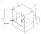
- FIG. 1 is a diagram showing a safety management system including a safety management device according to this embodiment.
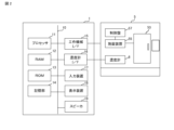
- FIG. 2 is a hardware configuration diagram of the safety management device according to this embodiment.
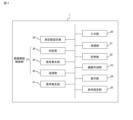
- FIG. 3 is a functional block diagram of the safety management device according to this embodiment.
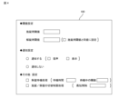
- FIG. 4 is a diagram showing an example of a condition setting screen displayed on the display unit of FIG.
- FIG. 5 is a supplementary diagram for explaining the measurement value setting process performed by the measurement value setting unit in FIG.
- FIG. 6 is a first supplementary diagram for explaining a control procedure for locking/unlocking the door of the workshop by the safety management device according to this embodiment.
- FIG. 7 is a second supplementary diagram for explaining the control procedure for locking/unlocking the door to the workshop by the safety management device according to this embodiment.
- FIG. 8 is a third supplementary diagram for explaining the control procedure for locking/unlocking the door to the workshop by the safety management device according to this embodiment.
- FIG. 9 is a supplementary diagram for explaining the unlocking standby process
- Machine tool A machine tool is a device that performs a predetermined process such as manufacturing a molded part, or bonding or machining a molded part to a supplied workpiece.
- the machine tool refers to various devices that generate oil mist during operation, such as a turning machine or a cutting machine.
- Machine room A space that is partitioned from the outside space by a cover that covers the entire machining tool.
- the machine room is one element that constitutes a machine tool.
- the machine room may be a room in which the machine tool is located. In this embodiment, the machine room has a door.
- Locking device A device configured to be able to lock/unlock the door of the workroom. Typically, the locking device is an element constituting the machine tool. However, the locking device may be an external device independent of the machine tool.
- Control panel A device that controls the locking/unlocking of the door at the entrance to the work room. Typically, the control panel is one of the components that make up the machine tool. However, the control panel may be an external device independent of the machine tool or a higher-level device connected to the machine tool. The control panel is realized by a numerical control device, a PC, etc.
- Concentration meter A device that measures the oil mist concentration in the work chamber.
- the concentration meter is an external device independent of the machine tool.
- the concentration meter may be one of the components that make up the machine tool.
- the concentration meter itself may be placed inside the work chamber, or the main body of the concentration meter may be placed outside the work chamber and only the sensor part may be placed inside the work chamber.
- the safety management device 2 is a device that functions as the core of the safety management system 1.
- the safety management system 1 has the safety management device 2, a machine tool 5, a concentration meter 6, and a mist collector 7.
- the machine tool 5 has a work room 52, a door 53 installed at the entrance of the work room 52, a locking device 55 for locking the door 53, and a control panel 57 for controlling the locking and unlocking operations of the locking device 55.
- the control panel 57 controls the locking device 55 to lock the door 53 upon receiving a locking signal from the safety management device 2, and controls the locking device 55 to unlock the door 53 upon receiving an unlocking signal.
- the control panel 57 has the normal door control function of the machine tool 5, and for example, controls the locking device 55 to lock the door 53 upon the start of operation of the machine tool 5, and controls the locking device 55 to unlock the door 53 upon the end of operation.
- the concentration meter 6 measures the oil mist concentration in the work room 52 and transmits concentration information indicating the oil mist concentration to the safety management device 2 .
- the mist collector 7 is a device that collects oil mist generated in the work chamber 52.
- the mist collector 7 is installed outside the work chamber 52 and is connected to the work chamber 52 via a duct 71. When the fan motor of the mist collector 7 is driven, the oil mist in the work chamber 52 is collected into the mist collector 7 together with the air in the work chamber 52. As a result, the concentration of the oil mist in the work chamber 52 is gradually reduced.
- FIG. 2 is a hardware configuration diagram of the safety management device 2. As shown in FIG. 2, a RAM 12, a ROM 13, a storage device 14, a machine tool I/F 15, a concentration meter I/F 16, an input device 17, a display device 18, and a speaker 19 are connected to a processor 11 via a data/control bus 10.
- the processor 11 is realized by a CPU, a GPU, etc.
- the RAM 12 functions as the main memory, work area, etc. of the processor 11.
- the ROM 13 stores the BIOS, OS, etc.
- the storage device 14 stores a safety management program. The various data stored in the storage device 14 may be recorded on removable media and distributed to users, or may be distributed by being downloaded to the safety management device 2 via a network.
- the machine tool 5 is connected to the machine tool I/F 15.
- a lock signal or unlock signal is sent from the safety management device 2 to the machine tool 5 via the machine tool I/F 15.
- the concentration meter 6 is connected to the concentration meter I/F 16.
- the safety management device 2 receives concentration information indicating the oil mist concentration in the work room 52 from the concentration meter 6 via the concentration meter I/F 16.
- the input device 17 is realized by a keyboard, mouse, jog, etc. A user can input various information to the safety management device 2 via the input device 17.
- the display device 18 is realized by an organic EL display, LCD, etc.
- the display device 18 displays various screens according to the control of the processor 11.
- the speaker 19 generates sounds indicating warnings or alarms according to the control of the processor 11.
- FIG. 3 is a functional block diagram of the safety management device 2.
- the safety management device 2 When the safety management program loaded from the storage device 14 to the RAM 12 is executed by the processor, the safety management device 2 functions as an input unit 30, a receiving unit 31, a storage unit 32, a screen creation unit 33, a display unit 34, a condition setting unit 35, a measurement value setting unit 36, a lock/unlock control unit 37, and a sound generating unit 41.
- the input unit 30 is a function related to the input device 17 in FIG. 2, and inputs user operations to the safety management device 2.
- the receiving unit 31 receives a concentration signal (concentration information) indicating the oil mist concentration from the concentration meter 6.
- the memory unit 32 is a function related to the memory device 14 in FIG. 2, and stores various information related to the processing of the safety management program. The various information stores various conditions set by the condition setting unit 35.
- the screen creation unit 33 displays various screens related to the safety management program. Specifically, the screen creation unit 33 creates a condition setting screen, an oil mist concentration screen, a warning screen, etc. The warning screen is created when notification by display is set on the condition setting screen.
- the warning screen includes marks, symbols, and text information for allowing the user to recognize that the oil mist concentration has exceeded the locking threshold.
- the warning screen may be displayed superimposed on the oil mist concentration screen.
- the display unit 34 is a function related to the display device 18 in FIG. 2, and displays the condition setting screen, oil mist concentration screen, warning screen, etc. created by the screen creation unit 33.
- the oil mist concentration screen displays, as information representing the oil mist concentration, for example, a graph showing the change in oil mist concentration over time.
- the condition setting unit 35 sets various conditions according to user operations on the condition setting screen. Details of the condition setting screen and the condition setting process by the condition setting unit 35 will be described later.
- the measurement value setting unit 36 sets the measurement value of the oil mist concentration to be used in the judgment process by the judgment unit 38 described below. Specifically, among the measurement values measured by the concentration meter 6, erroneous measurement values are excluded from the measurement value of the oil mist concentration to be used in the judgment process. Details of the measurement value setting process by the measurement value setting unit 36 will be described later.
- the locking/unlocking control unit 37 generates a locking signal for locking the door 53 or an unlocking signal for unlocking the door 53 based on the measured value of the oil mist concentration set by the measurement value setting unit 36.
- the locking/unlocking control unit 37 restricts the generation of an unlocking signal until the time (second time) specified by the minimum interval has elapsed since the generation of a locking signal.
- the locking/unlocking control unit 37 does not generate an unlocking signal until the time (second time) specified by the minimum interval has elapsed since the generation of a locking signal.
- the locking/unlocking control unit 37 executes normal processing. As a result, locking/unlocking is not switched at intervals shorter than at least the minimum interval, and therefore a decrease in the workability of the worker can be suppressed.
- the locking/unlocking control unit 37 has a determination unit 38, a signal generating unit 39, and a transmission unit 40.
- the determination unit 38 determines whether the door 53 is locked or unlocked based on the measured value of the oil mist concentration set by the measurement value setting unit 36.
- the signal generating unit 39 generates a locking signal for locking the door 53 or an unlocking signal for unlocking the door 53 according to the determination result of the determination unit 38.
- the transmission unit 40 transmits the locking signal or unlocking signal generated by the signal generating unit 39 to the machine tool 5.
- the sound generating unit 41 is a function related to the speaker 19 in FIG. 2, and functions when sound notification is set on the condition setting screen.
- the sound generating unit 41 When the determination unit 38 determines that the door 53 is locked, the sound generating unit 41 generates a sound (alarm sound) to notify the user as a warning or alarm that the oil mist concentration in the work room 52 is high and the door 53 is locked.
- the sound generating unit 41 also generates a sound to notify the user that the oil mist concentration in the work room 52 has decreased and the door 53 has been unlocked.
- FIG. 4 is a diagram showing an example of a condition setting screen displayed on the safety management device 2 according to this embodiment.
- the condition setting screen 100 is configured to allow various conditions related to the control of locking/unlocking of the door 53 to be set.
- the condition setting screen 100 includes a plurality of items.
- the item "Threshold setting" includes an input field for the locking threshold, an input field for the unlocking threshold, and a selection box for making the unlocking threshold the same as the locking threshold.
- the condition setting unit 35 sets the locking threshold and the unlocking threshold by a user operation on the input form included in the item "Threshold setting".
- the item "Notification setting” includes a radio button for selecting whether or not to notify that the oil mist concentration is high, and a selection box for the notification method (audio, display) when notifying.
- the condition setting unit 35 sets the notification method by a user operation on the input form included in the item “Notification setting”.
- the item "Other Settings” includes a selection box for setting the unlocking standby process and a selection box for setting the locking/unlocking switching restriction process. It also includes an input field for the standby time (first time) when the unlocking standby process is set, an input field for the standby threshold, and an input field for the shortest interval when the locking/unlocking switching restriction process is set.
- the standby threshold is set to a value greater than the unlocking threshold and less than or equal to the locking threshold.
- the condition setting unit 35 sets the unlocking standby process and the locking/unlocking switching restriction process by operating the input form included in the item "Other Settings”.
- FIG. 5 is a supplementary diagram supplementing the description of the measurement value setting process by the measurement value setting unit 36, and is a graph showing the change in oil mist concentration over time.
- the measurement values M1 to M7 represent the oil mist concentrations measured by the concentration meter 6 at time points t1 to t7, respectively. As shown at time point t7 in FIG. 5, if the concentration meter 6 had measured correctly, the oil mist concentration would have been higher than the unlocking threshold value.
- the measurement value setting unit 36 excludes the measurement values of the oil mist concentration measured by the concentration meter 6 that have been erroneously measured due to an error, malfunction, or the like from the measurement values used in the judgment process by the judgment unit 38.
- the measurement value setting unit 36 calculates the approximated line 200 using a number of measurement values M1 to M6 measured up to that point, and when the displacement of the current measurement value M7 from the expected value M7' calculated from the approximated line 200 is greater than a threshold value, the measurement value setting unit 36 excludes the measurement value M7 from the object of the judgment process by the judgment unit 38.
- the judgment method is not limited to the above. For example, when the absolute value of the displacement of the current measurement value from the measurement value measured immediately before is greater than a threshold value, the measurement value setting unit 36 may exclude the current measurement value from the object of the judgment process.
- the measurement value setting process by the measurement value setting unit 36 can set multiple measurement values M1 to M6 and M8, excluding measurement value M7 shown in FIG. 5, as targets for judgment processing by the judgment unit 38, thereby preventing the door 53 from being erroneously unlocked at time t7 and then locked again at time t8. This contributes to ensuring the safety of the worker. In addition, the frequency of locking/unlocking can be reduced, which also contributes to preventing a decrease in workability by the worker.
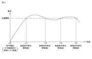
- Fig. 6 is a graph showing an example of the change over time in the oil mist concentration in the workshop 52 measured by the concentration meter 6.
- the locking threshold and the unlocking threshold are set to the same value (referred to as a common threshold).
- the door 53 is locked and the mist collector 7 is driven by control on the machine tool 5 side.
- Oil mist is generated in the work chamber 52 by the machine tool 5, and if the amount of oil mist generated is greater than the amount of oil mist collected by the mist collector 7, the oil mist concentration in the work chamber 52 increases.
- the safety management device 2 generates a locking signal when the oil mist concentration in the work chamber 52 exceeds the common threshold (time t11). The generated locking signal is sent to the machine tool 5. Since the door 53 of the machine tool 5 is already in a locked state, that state is maintained.
- the safety management device 2 When the oil mist concentration in the machine room 52 falls below the common threshold (time t12), the safety management device 2 generates an unlocking signal. The generated unlocking signal is sent to the machine tool 5. When the control panel 57 of the machine tool 5 receives the unlocking signal from the safety management device 2, it controls the locking device 55 to unlock the door 53. As a result, the door 53 to the machine room 52 is unlocked.
- the safety management device 2 continues to control the locking/unlocking of the door 53 of the workroom 52.
- the safety management device 2 generates a locking signal when the oil mist concentration in the workroom 52 exceeds the common threshold again (time t13).
- the generated locking signal is sent to the machine tool 5.
- the control panel 57 of the machine tool 5 controls the locking device 55 to lock the door 53 when it receives the locking signal from the safety management device 2.
- the safety management device 2 generates an unlocking signal when the oil mist concentration in the workroom 52 falls below the common threshold (time t14).
- the generated unlock signal is sent to the machine tool 5.
- the control panel 57 of the machine tool 5 controls the locking device 55 to unlock the door 53.
- the door 53 to the work room 52 is unlocked again.
- the door 53 of the work room 52 can be kept locked.
- the door 53 of the work room 52 can be unlocked when the oil mist concentration drops to a safe concentration (unlocking threshold) that does not cause health damage to the operator.
- the operator can enter the work room 52 when the oil mist concentration drops to a safe concentration, so there is no need to wait an unnecessarily long time to enter the work room 52 because the operator cannot know whether the oil mist concentration in the work room 52 has dropped to a safe concentration, and it is possible to suppress a decrease in the operator's work efficiency.
- Figures 7 and 8 are graphs showing another first example of the change over time in the oil mist concentration in the workshop 52 measured by the concentration meter 6.
- Figure 7 shows the period from time t20 to time t27
- Figure 8 shows the period from time t27 to time t33.
- the unlocking threshold is set to a value lower than the locking threshold.
- the safety management device 2 When the operation of the machine tool 5 begins (time t20), the door 53 is locked by control on the machine tool 5 side, and the oil mist concentration in the work room 52 rises.
- the safety management device 2 generates a locking signal when the oil mist concentration in the work room 52 exceeds the locking threshold (time t21). Since the door 53 of the machine tool 5 is already locked, this state is maintained.
- the generation of oil mist stops, but on the other hand, the collection of oil mist by the mist collector 7 continues, so the oil mist concentration in the work room 52 gradually decreases.
- the safety management device 2 generates an unlocking signal when the oil mist concentration in the work room 52 falls below the unlocking threshold (time t27).
- time t21 when the oil mist concentration in the work room 52 exceeds the locking threshold, and time t27, when it falls below the unlocking threshold, some factor may cause the oil mist concentration in the work room 52 to rise and fall above the locking threshold. If the locking threshold and the unlocking threshold are the same, the door 53 to the work room 52 will repeatedly be locked and unlocked at times 22, 23, 24, 25, and 26, when the oil mist concentration crosses the locking threshold.
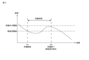
- FIG. 9 is a supplementary diagram for explaining the unlocking standby process by the locking/unlocking control unit 37.
- FIG. 9 shows a graph representing the change over time in the oil mist concentration in the work room 52 measured by the concentration meter 6.
- the safety management device 2 When the unlocking standby process is set on the condition setting screen 100, as shown in FIG. 9, the safety management device 2 generates an unlocking signal not at time t41 when the oil mist concentration falls below the unlocking threshold, but at time t42 when the standby time has elapsed since the time t41 when the oil mist concentration falls below the unlocking threshold.
- the oil mist concentration in the work room 52 decreases over time. Therefore, by unlocking the door 53 of the work room 52 not at time t41 when the oil mist concentration falls below the unlocking threshold, but at time t42 when the standby time has elapsed since time t41, the worker can work in a safer environment in which the oil mist concentration is lower than the unlocking threshold. In addition, because the time from when the door 53 was locked, prior to time t41, can be secured, it is possible to avoid the door 53 being locked/unlocked in a short period of time, thereby preventing a decrease in the workability of the workers.
- the safety management device 2 may continue to monitor the oil mist concentration even during the period from time t41 when the oil mist concentration falls below the unlocking threshold to time t42 when the standby time has elapsed, and generate an unlocking signal at time t42 when the standby time has elapsed when the oil mist concentration remains lower than the standby threshold (higher than the unlocking threshold and lower than the locking threshold).
- the unlocking standby process is terminated. After that, the unlocking standby process is started again when the oil mist concentration falls below the unlocking threshold again. This makes it possible to avoid the unlikely event that the oil mist concentration becomes much higher than the unlocking threshold once the waiting time has elapsed since the oil mist concentration fell below the unlocking threshold.
- the safety management device 2 comprises a receiving unit 31 that receives a concentration signal indicating the oil mist concentration from a concentration meter 6 that measures the oil mist concentration in a workshop 52 having a door 53 that can be locked/unlocked, and a lock/unlock control unit 37 that generates a locking signal when the oil mist concentration exceeds a locking threshold and generates an unlocking signal when the oil mist concentration falls below the unlocking threshold.
- a concentration signal indicating the oil mist concentration from a concentration meter 6 that measures the oil mist concentration in a workshop 52 having a door 53 that can be locked/unlocked
- a lock/unlock control unit 37 that generates a locking signal when the oil mist concentration exceeds a locking threshold and generates an unlocking signal when the oil mist concentration falls below the unlocking threshold.
- the unlocking threshold is the same as the locking threshold.
- the unlocking threshold value is lower than the locking threshold value.
- the lock/unlock control unit 37 In the safety management device 2 described in any one of Supplementary Notes 1 to 3, the lock/unlock control unit 37 generates an unlock signal when a predetermined first time has elapsed since the oil mist concentration fell below the unlocking threshold value. (Appendix 5) In the safety management device 2 described in Appendix 4, the locking/unlocking control unit 37 generates an unlocking signal if the oil mist concentration is maintained below a threshold value that is higher than the unlocking threshold and lower than the locking threshold during the first hour after the oil mist concentration falls below the unlocking threshold.
- the safety management device 2 described in any one of Supplementary Notes 1 to 5 further includes a display unit 34 that displays information regarding the oil mist concentration.
- the safety management device 2 described in Supplementary Notes 1 to 8 further includes a sound generating unit 41 that generates a sound representing a warning or an alarm when the oil mist concentration exceeds the locking threshold value.
Landscapes
- Engineering & Computer Science (AREA)
- Mechanical Engineering (AREA)
- Auxiliary Devices For Machine Tools (AREA)
Abstract
Un dispositif de gestion de sécurité selon la présente invention a pour fonction de commander le verrouillage/déverrouillage de la porte d'une machine-outil telle qu'un tour ou une machine de coupe. Plus particulièrement, le dispositif de gestion de sécurité est pourvu : d'une unité de réception qui reçoit un signal de concentration représentant une concentration de brouillard d'huile provenant d'un compteur de concentration qui mesure la concentration de brouillard d'huile dans un atelier équipé d'une porte verrouillable/déverrouillable ; et d'une unité de commande de verrouillage/déverrouillage qui génère un signal de verrouillage lors d'un déclenchement par une concentration de brouillard d'huile qui dépasse une valeur seuil de verrouillage, et qui génère un signal de déverrouillage lors d'un déclenchement par la concentration de brouillard d'huile s'inscrivant en dessous d'une valeur seuil de déverrouillage.
Priority Applications (1)
| Application Number | Priority Date | Filing Date | Title |
|---|---|---|---|
| PCT/JP2023/030149 WO2025041263A1 (fr) | 2023-08-22 | 2023-08-22 | Dispositif de gestion de sécurité |
Applications Claiming Priority (1)
| Application Number | Priority Date | Filing Date | Title |
|---|---|---|---|
| PCT/JP2023/030149 WO2025041263A1 (fr) | 2023-08-22 | 2023-08-22 | Dispositif de gestion de sécurité |
Publications (1)
| Publication Number | Publication Date |
|---|---|
| WO2025041263A1 true WO2025041263A1 (fr) | 2025-02-27 |
Family
ID=94731524
Family Applications (1)
| Application Number | Title | Priority Date | Filing Date |
|---|---|---|---|
| PCT/JP2023/030149 Pending WO2025041263A1 (fr) | 2023-08-22 | 2023-08-22 | Dispositif de gestion de sécurité |
Country Status (1)
| Country | Link |
|---|---|
| WO (1) | WO2025041263A1 (fr) |
Citations (2)
| Publication number | Priority date | Publication date | Assignee | Title |
|---|---|---|---|---|
| JPH11156664A (ja) * | 1997-12-01 | 1999-06-15 | Enshu Ltd | 不燃性ガス濃度によるドアインターロツク装置 |
| JP6915131B1 (ja) * | 2020-06-09 | 2021-08-04 | Dmg森精機株式会社 | 加工機械 |
-
2023
- 2023-08-22 WO PCT/JP2023/030149 patent/WO2025041263A1/fr active Pending
Patent Citations (2)
| Publication number | Priority date | Publication date | Assignee | Title |
|---|---|---|---|---|
| JPH11156664A (ja) * | 1997-12-01 | 1999-06-15 | Enshu Ltd | 不燃性ガス濃度によるドアインターロツク装置 |
| JP6915131B1 (ja) * | 2020-06-09 | 2021-08-04 | Dmg森精機株式会社 | 加工機械 |
Similar Documents
| Publication | Publication Date | Title |
|---|---|---|
| CN109863376B (zh) | 用于作业机械的振动监测方法和系统 | |
| KR101300301B1 (ko) | 작업 기계의 채터링 억제 방법 및 장치 | |
| US10228677B2 (en) | Vibration information display device for machine tool that acquires information only during time that vibration value and rate of change exceed respective threshold | |
| CN114555292B (zh) | 作业机械的加工状态监视方法以及系统 | |
| US10429404B2 (en) | Electronic device having impact detecting function | |
| JP7085370B2 (ja) | 診断装置、診断システム、診断方法およびプログラム | |
| US11256229B2 (en) | Industrial machinery and control method thereof | |
| JP2016083759A (ja) | 作業機械の加工状態監視方法及びシステム | |
| CN114555291B (zh) | 作业机械的加工状态监视方法以及系统 | |
| JP6673002B2 (ja) | 情報処理装置、情報処理方法、情報処理プログラム、および情報処理システム | |
| CN111052016B (zh) | 用于对机床进行监控的方法 | |
| JP6722372B2 (ja) | 工具認識機能を有した工作機械監視予測制御装置 | |
| JP7091743B2 (ja) | 情報処理装置、情報処理方法、プログラム、および機械装置 | |
| JP6575814B2 (ja) | 作業機械の加工状態監視方法及びシステム | |
| JP2006154998A (ja) | 制御装置 | |
| JP2020037166A (ja) | 電動工具および電動工具システム | |
| JP5660850B2 (ja) | 振動表示装置 | |
| US5773949A (en) | Cutter fracture detecting system | |
| JP5637840B2 (ja) | 振動検出方法 | |
| JP6526583B2 (ja) | 切削機械監視装置 | |
| CN114102262A (zh) | 一种机床主轴安全检测方法、系统及机床 | |
| Shamsuzzaman et al. | Integrated control chart system for time-between-events monitoring in a multistage manufacturing system | |
| JP2018111171A (ja) | 異常予兆検知システム及び異常予兆検知方法 | |
| US20190155250A1 (en) | Noise monitoring device | |
| JP2003271213A (ja) | 移動軸監視装置、移動軸監視方法、移動軸監視プログラムおよびその移動軸監視プログラムを記録したコンピュータ読取り可能な記録媒体 |
Legal Events
| Date | Code | Title | Description |
|---|---|---|---|
| 121 | Ep: the epo has been informed by wipo that ep was designated in this application |
Ref document number: 23949724 Country of ref document: EP Kind code of ref document: A1 |
|
| ENP | Entry into the national phase |
Ref document number: 2025541215 Country of ref document: JP Kind code of ref document: A |
|
| WWE | Wipo information: entry into national phase |
Ref document number: 2025541215 Country of ref document: JP |
|
| NENP | Non-entry into the national phase |
Ref country code: DE |