WO2025041258A1 - Émetteur occ, récepteur occ, procédé de génération de signal occ, procédé de réception de signal occ et programme - Google Patents
Émetteur occ, récepteur occ, procédé de génération de signal occ, procédé de réception de signal occ et programme Download PDFInfo
- Publication number
- WO2025041258A1 WO2025041258A1 PCT/JP2023/030127 JP2023030127W WO2025041258A1 WO 2025041258 A1 WO2025041258 A1 WO 2025041258A1 JP 2023030127 W JP2023030127 W JP 2023030127W WO 2025041258 A1 WO2025041258 A1 WO 2025041258A1
- Authority
- WO
- WIPO (PCT)
- Prior art keywords
- signal
- occ
- dimmer
- codebook
- low
- Prior art date
- Legal status (The legal status is an assumption and is not a legal conclusion. Google has not performed a legal analysis and makes no representation as to the accuracy of the status listed.)
- Pending
Links
Images










Classifications
-
- H—ELECTRICITY
- H04—ELECTRIC COMMUNICATION TECHNIQUE
- H04B—TRANSMISSION
- H04B10/00—Transmission systems employing electromagnetic waves other than radio-waves, e.g. infrared, visible or ultraviolet light, or employing corpuscular radiation, e.g. quantum communication
- H04B10/11—Arrangements specific to free-space transmission, i.e. transmission through air or vacuum
- H04B10/114—Indoor or close-range type systems
-
- H—ELECTRICITY
- H04—ELECTRIC COMMUNICATION TECHNIQUE
- H04B—TRANSMISSION
- H04B10/00—Transmission systems employing electromagnetic waves other than radio-waves, e.g. infrared, visible or ultraviolet light, or employing corpuscular radiation, e.g. quantum communication
- H04B10/50—Transmitters
- H04B10/516—Details of coding or modulation
Definitions
- the disclosed technology relates to dimming control and encoding technology for optical camera communication.
- Optical camera communication is a visible light communication method that uses a light source, such as an LED display, as the transmitting means and a camera as the receiving means.
- the transmitting side transmits a digital signal by modulating the light emitted by a light source such as an LED. Modulation is performed by controlling the light source to be turned on and off.
- Non-Patent Document 1 The IEEE 802.15.7m group (TG 7m) introduced visible light Region-of-Interest (RoI) signaling into vehicular OCC systems (Non-Patent Document 1). This technology allows OCC systems to transmit low-rate and high-rate data streams simultaneously.
- the high-rate stream is used for high-speed data communication over the selected RoI.
- Hybrid modulation schemes such as Twinkle Variable Pulse Position Modulation (VPPM) and Hybrid Spatial Phase-Shift Keying (HS-PSK) are often used to modulate the low-rate and high-rate streams.
- VPPM Twinkle Variable Pulse Position Modulation
- HS-PSK Hybrid Spatial Phase-Shift Keying
- the high-rate stream is modulated by Twinkle VPPM (Non-Patent Document 2) or Dimming Spatial-8 Phase-Shift Keying (DS8-PSK) (Non-Patent Document 1)
- the low-rate stream is modulated by Undersampled Frequency-Shift On-Off Keying (UFSOOK), Undersampled Phase-Shift On-Off Keying (UPSOOK), or Spatial-2 Phase-Shift Keying (S2-PSK).
- UFSOOK Frequency-Shift On-Off Keying
- UPSOOK Undersampled Phase-Shift On-Off Keying
- S2-PSK Spatial-2 Phase-Shift Keying
- Both streams transmitted from the RoI are decoded by the dual-camera receiver, where the high-speed (HS) camera demodulates the high-rate stream and the low-speed (LS) camera demodulates the low-rate stream. This reduces the computational load on the high-speed camera-based receiver.
- HS high-speed
- LS low-speed
- Dimming control is one of the key issues in OCC and visible light communication (VLC) systems.
- Traditional approaches use correction symbol insertion and puncturing for dimming control, which adds a large number of redundant bits to the frame, reducing the achievable transmission rate.
- the dimming level can be managed by adjusting the proportion of the optical bit stream that is OFF (hereafter referred to as "logic 0") or ON (hereafter referred to as "logic 1") between 0% and 100%.
- Dimming control in HS-PSK and Twinkle VPPM involves changing the duty cycle (length of ON or OFF) of the high-rate pulse groups. This makes demodulation difficult for DS8-PSK and Twinkle VPPM signals, which require each optical pulse to be synchronized, sampled, and decoded with strict timing.
- run-length-limited (RLL) codes maintain direct current (DC) balance by having an equal number of logical 1s and logical 0s in each symbol.
- the soft-input soft-output (SISO) RLL decoder introduced by Kim et al. improves system reliability by generating soft outputs for the soft-decision (SD) FEC decoding algorithm.
- SD soft-decision
- the decoding algorithm for SISO RLL codes is complex and cannot be integrated into the VLC receiver.
- Non-Patent Document 3 proposed probabilistic shaping for RoI signaling applications (Non-Patent Document 3), but implementation remains challenging.
- an OCC transmitter includes a dimmer and an on-off keying modulation unit.
- the dimmer converts the high-rate signal based on the low-rate signal using m-out-of-n encoding to generate a superimposed signal that provides the two desired dimming levels.
- a codebook for m-out-of-n encoding is generated using a set of bit sequences Cm having m logical 1s or logical 0s in n bits, and pairs Cm-l and Cm+l (l is a natural number).
- the on-off keying modulator converts the signal output from the dimmer into an optical signal.
- an OCC receiver which receives an OCC signal transmitted by an OCC transmitter, includes a low-speed camera, an RoI identification unit, a high-speed camera, an on-off keying demodulation unit, and an inverse dimmer.
- the low-speed camera captures the OCC signal and outputs a low-rate signal.
- the RoI determination unit determines the RoI from the low rate signal.
- the high-speed camera extracts the RoI from the camera's field of view and outputs an RoI shooting signal.
- the on-off keying demodulation unit demodulates the RoI imaging signal to obtain a superimposed signal.
- the inverse dimmer uses a codebook to decode the high rate signal from the superimposed signal.
- the disclosed 4p-EMDPM dimmer-based visible light RoI signaling technique enables easier clock tracking and synchronization compared to the conventional twinkle VPPM approach.
- the disclosed 4p-EMDPM method reduces rate loss (bit redundancy) due to probabilistic shaping more than conventional methods.
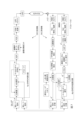
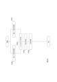
- FIG. 2 is a functional block diagram of an OCC transmitter and an OCC receiver according to an embodiment.
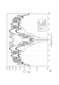
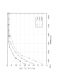
- a comparison of rate loss for different distribution matching schemes. A comparison of rate losses among MPDM, EMPDM, 2p-EMPDM, and 4p-EMPDM.
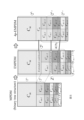
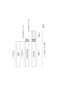
- Functional block diagram of the 4p-EMPDM dimmer and codebook structure diagram. A diagram showing the codebook structures of MPDM, EMPDM, and 4p-EMPDM.
- a diagram showing the binary tree structure of 4p-EMPDM. 4 is a diagram for explaining details of the flow of digital signal processing in an OCC transmitter and an OCC receiver according to an embodiment.
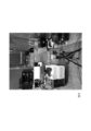
- FIG. Photograph of the low-speed RoI signaling-high-speed OCC demonstration system showing the OCC transmitter, low-speed camera, and video monitor.
- a photo of the low-speed RoI signaling-high-speed OCC demonstration system showing the OCC transmitter, high-speed camera, and OCC receiver.
- the relationship between exposure time and pixel Eb/N 0 was measured by changing the distance between the transmitter and receiver.
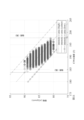
- FIG. 1 shows two-class classification using intensity domain thresholding.
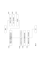
- FIG. 4 is a flowchart illustrating the operation of the OCC transmitter 1.
- FIG. 4 is a flowchart illustrating the operation of the OCC receiver 2.
- FIG. 2 is a diagram showing an example of the functional configuration of a computer.
- the disclosed technology provides binary extended multiset-partition distribution matching (EMPDM) with four composition pairs (4p), and a dimmer based on 4p-EMPDM for visible light RoI signaling applications.
- EPDM binary extended multiset-partition distribution matching
- ⁇ will have a slightly different value than PA(1).
- LPS Layered Probabilistic Shaping
- SPE systematic polar encoder
- the 4p-EMPDM dimmer shapes the information word ⁇ such that the proportion of logical 1s and logical 0s is not significantly different. As a result, the run length of y is limited to the range that does not cause flicker at the minimum optical clock rate.
- the frequency of occurrence of logic 1 and logic 0 in codeword u (e.g., "1011101011” has “three 0s and seven 1s") is called a "composition.”
- a composition with a frequency of occurrence of logic 1 i is represented as ⁇ i .
- the sequence "1011101011” belongs to ⁇ 7 .
- a low-speed global shutter camera with a frame rate of 30 fps and long exposure time detects the dimming level of a Light Emission Diode (LED), which decodes the logic 0s and 1s in a low-rate bitstream that is used for RoI identification.
- the high-speed camera decodes the high-rate data stream on the RoI detected by the low-speed camera at a high frame rate (e.g., 10,000 fps).
- the SD successive canceling SPD decodes the codeword y' into u'.
- the inverse 4p-EMPDM dimmer decodes the message u' to reconstruct the high-speed binary sequence ⁇ ', assuming that all transmission errors have been corrected by SD-SPD.
- the modulation technique chosen was OOK due to its simplicity and popularity in the VLC system. Since the code word u is a combination of a low-rate signal and a high-rate signal, the code word u and the code word u' before decoding (inverse dimming) are sometimes referred to as "superimposed signals" in this specification.
- the matching rate R DM which indicates how many bits of information are transmitted with each bit coded in binary DM, is defined by the following equation (1). where is an inequality Then, the largest k that satisfies is output.
- CCDM Constant Composition Distribution Matching
- MPDM was introduced as a method to reduce rate loss, especially for short block lengths, and is suitable for practical implementation (Non-Patent Document 4).
- the rate loss reduction of MPDM comes from the inclusion of multiple Composition Pairs (CPs) in addition to a Typical Composition (TC) to generate a non-fixed composition DM.
- CPs Composition Pairs
- TC Typical Composition
- the compositions used in a pair are complementary to each other, such that the probabilistic average of the sequences generated by both compositions achieves the desired distribution.
- Non-Patent Document 4 introduced a binary tree structure in which each information word is divided into a payload that is mapped to a binary CCDM sequence and a prefix that selects the composition.
- MPDM which requires the sequence number of a particular composition to be rounded to the nearest power of 2 (power of 2 constraint)
- the disclosed technology proposes binary EMPDM, which lifts the power of 2 constraint for each composition and extends the codebook of conventional matching.
- EMPDM which lifts the power of 2 constraint for each composition and extends the codebook of conventional matching.
- Cm represents a binary group of n elements of weight m, forming the codebook of TC.
- C i denote the number of elements in C i
- the number of permutations in the codebook of composition pairs ⁇ m ⁇ l , ⁇ m+l ⁇ (l>0) can be calculated as follows:
- the total number of permutations in the EMPDM codebook including TC and all CPs is given by:
- the rate loss of EMPDM, ⁇ EMPDM is estimated by replacing R EMPDM in equation (10) with R DM in equation (4).
- FIG. 11 shows the rate loss for several examples of MPDM and EMPDM, including codebooks with TC and two leading CPs (2p-EMPDM), four leading CPs (4p-EMPDM), and all CPs (EMPDM).
- 4p-EMPDM is a compact version of EMPDM that generates only run-length aware codewords (codewords with a maximum run-length bounded to a predefined value) for the purpose of reducing flicker in VLC applications.
- Arrow 31 shows the empirical shaping range for low-level dimming (logic 0) and arrow 32 shows the empirical shaping range for high-level dimming (logic 1).
- the run-length-aware shaping range for VLC applications is marked with a shaded box. Comparing EMPDM in Figure 2 with 4p-EMPDM in Figure 3, we can see that the rate loss of 4p-EMPDM is equivalent to that of EMPDM. In particular, there is no difference in the range of PA(1) ⁇ 45% at low level dimming and in the range of PA(1)>55% at high level dimming.
- the rate loss of 2p-EMPDM increases as a penalty for not including the third and fourth CPs in the codebook.
- FIG 4 shows a detailed functional block diagram and codebook structure of the 4p-EMPDM dimmer 11 in Figure 1.
- EPDM Extended MPDM
- FIG. 5 shows the codebook structures of conventional MPDM, EMPDM, and 4p-EMPDM.
- EMPDM is an extension of the MPDM codebook because its composition codebook does not have a power-of-two constraint.
- the 4p-EMPDM codebook has a binary tree structure, and adjacent compositions share the codebook.
- the 4p-EMPDM codebook contains only four CPs in addition to the TC. This is because the size of the codebook for the remaining CPs is not significant compared to the size of the codebook for the four CPs.
- the total number of output sequences of the two-level 4p-EMPDM dimmer is however, represents a function that rounds to the nearest power of two.
- Figure 6 shows the binary tree structure of 4p-EMPDM.
- a Huffman code is used to determine the prefix that identifies the subset pair.
- the first p l bits (1 or 2 bits) are used for the prefix.
- the next bit (the first bit of the payload) selects the shared subset in the subset pair.
- the prefix and the first bit of the payload are sometimes collectively referred to as the "selection code.”
- Shared exemplar-pairwise subset The codebook of a TC is shared with the codebook of its paired composition element, e.g., the subset with (C m , C m ⁇ 1 ) and (C m , C m+1 ).
- shared Pairwise Subsets A codebook is shared between two pairs of composition elements, e.g., the subsets with (Cm -1 , Cm -2 ), (Cm +1 , Cm +2 ), (Cm -2 , Cm -3 , Cm -4 ), and (Cm +2 , Cm +3 , Cm +4 ).
- Each subset of leaf nodes applies binary CCDM based on m-out-of-n codes to map the remaining kl- bit payload one-to-one to a shaped sequence.
- the OCC transmitter 1 includes a dimmer 11 (4p-EMPDM dimmer), an FEC encoding unit 12 (systematic polar encoding unit), an OOK modulation unit 13, and an LED 14.
- a dimmer 11 (4p-EMPDM dimmer)
- FEC encoding unit 12 systematic polar encoding unit
- OOK modulation unit 13 an LED 14.
- the low rate signal v and the high rate signal ⁇ are input to the dimmer 11 (steps S1801 and S1802). Based on the low-rate signal and the high-rate signal, the dimmer 11 converts the high-rate signal into an m-out-of-n code using the codebook, and outputs a superimposed signal (step S1803).
- the FEC encoder 12 encodes the superimposed signal using, for example, a systematic polar code, and outputs an FEC code (step S1804).
- the OOK modulator 13 modulates the FEC code to drive the LED 14 and output an OCC signal (step S1805).
- the OCC receiver 2 includes a low-speed camera 21, a high-speed camera 22, an RoI identifying unit 23, an OOK demodulating unit 24, an FEC decoding unit 25 (systematic polar decoding unit), and an inverse dimmer 26 (4p-EMPDM inverse dimmer).
- the low-speed camera 21 captures the entire camera field of view and outputs it to the RoI identifying unit 23 (step S1901).
- the RoI identifying unit 23 detects a low rate signal from the camera's field of view (step S1902).
- the RoI identifying unit 23 identifies the RoI in the field of view from the detected low-rate signal (step S1903), and outputs the RoI information to the high-speed camera 22. Based on the RoI information, the high-speed camera 22 extracts the RoI portion from the imaging signal (camera field of view) and outputs the RoI imaging signal (step S1904).
- the OOK demodulation unit 24 demodulates the RoI imaging signal and outputs the FEC code (step S1905).
- the FEC decoding unit 25 decodes the superimposed signal from the FEC code (step S1906).
- the inverse dimmer 26 decodes the high-rate signal from the superimposed signal using the m-out-of-n encoding codebook generated in the same manner as the dimmer 11 (step S1907).
- FIG. 7 shows the flow of digital signal processing (DSP) for the proposed transmitter and receiver, and the experimental setup. 8 and 9 show the low-rate RoI signaling-high-rate OCC demonstration system.
- FIG. 17 summarizes the setup of the low-rate and high-rate experimental systems.
- the low-rate RoI signal receiver used a 30 fps low-speed global-shutter camera to detect the dimming level and decode the low-rate bitstream.
- An Atmos Shogun 7 with SSD mini-storage served as the video capture and monitoring device.
- VLC transmitters with low-power LEDs were placed at distances of 1.7 m, 2.9 m, and 4.2 m from the receiver.
- HS camera/OCC Receiver high-speed camera receiver
- FPGA field programmable gate array
- noise affects image quality has been widely studied in the literature.
- the impact of noise varies from one imaging system to another.
- noise is modeled as a Gaussian distribution.
- the main noise sources are thermal noise generated by the readout circuitry and shot noise due to background illumination.
- the variance of the shot noise is proportional to the area of the received pixel and the received light intensity.
- CMOS complementary metal-oxide semiconductor
- N 0 the noise density
- E b the bit energy
- a the mark and space amplitude
- ⁇ and ⁇ fitting parameters.
- a camera with a long exposure time can be considered as a low-pass filter that attenuates high-frequency signals. Therefore, adjusting the exposure time has a large effect on pixel Eb/N 0 .
- pixel Eb/ N0 changes with the exposure time of the CMOS camera.
- Te exceeds 4500 ⁇ s
- pixel Eb/ N0 saturates at about 39.7dB at distances of 1.7m, 2.9m, and 4.2m.
- Te 6400 ⁇ s.
- pixel Eb/ N0 is 39.74dB.
- Figure 11 shows how noise affects the intensity I and area A of a 50% dimming symbol.
- a low threshold, a median threshold, and a high threshold are used to determine a threshold range, which is the range between a low threshold and a high threshold.
- the within-class variance due to noise effects determines the width of the range.
- the threshold range is defined to avoid ambiguity in detecting close dimming levels.
- the median threshold is given by the following equation (14): where s and b represent the slope and y-intercept of the threshold line, respectively, and can be calculated using the following equations (15) and (16). where A and I represent the area (width ⁇ height) and average intensity of the captured pixels, respectively.
- the high and low threshold lines can be determined using a linear equation.
- b h and b l are determined by substituting the coordinates of the furthest points above and below the central threshold in equation (14).
- Two-class classification by intensity domain threshold is shown in Figure 13.
- the camera captures the dimming symbol shaped by the 4p-EMPDM dimmer.
- Both the intensity and area of a captured pixel are used to determine an intensity-area threshold.
- the camera-based receiver is placed 4.2 m away from the VLC transmitter.
- a typical shaping level is close to 50%; specifically, 30% to 41% is a logical 0 and 70% to 59% is a logical 1.
- the rate loss of the dimmer decreases from 0.031 to 0.0165 (Fig. 3), which means that the matching rate increases with the proposed area-intensity threshold.
- 4p-EMPDM Dimmer As explained in the section [4p-EMPDM Dimmer and Its Implementation Method], the 4p-EMPDM dimmer generates only sequences with no significant difference in the ratio of logic 0s and logic 1s. Therefore, compared to other binary distribution matching techniques, 4p-EMPDM is suitable for non-RLL VLC systems because the run length of its output sequence is constrained to mitigate flicker.
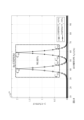
- Figure 15 shows the overhead of the 4p-EMPDM dimmer and FEC coding.
- the coding overhead is the ratio of the number of redundant bits to the number of information bits and can be expressed as a percentage.
- the overhead of 4p-EMPDM is 4.16%, and the overhead of SPE(FEC) is 28%.
- a low-rate logic level is created from two dimming levels, therefore, the power distributions of the LPS symbols corresponding to the two dimming levels must not overlap in order to be identified by a low-speed camera-based receiver.
- the program describing this processing can be recorded on a computer-readable recording medium.
- Examples of computer-readable recording media include magnetic recording devices, optical disks, magneto-optical recording media, and semiconductor memories.
- the program may be distributed, for example, by selling, transferring, or lending portable recording media such as DVDs or CD-ROMs on which the program is recorded. Furthermore, the program may be stored in a storage device of a server computer, and the program may be distributed by transferring the program from the server computer to other computers via a network.
- a computer that executes such a program for example, first stores in its own storage device the program recorded on a portable recording medium or the program transferred from a server computer. Then, when executing a process, the computer reads the program stored on its own recording medium and executes the process according to the read program. As another execution form of the program, the computer may read the program directly from the portable recording medium and execute the process according to the program, or may execute the process according to the received program each time a program is transferred from the server computer to the computer.
- the above-mentioned process may also be executed by a so-called ASP (Application Service Provider) type service that does not transfer the program from the server computer to the computer, but realizes the processing function only by issuing an execution instruction and obtaining the results.
- ASP Application Service Provider
- the program in this form includes information used for processing by an electronic computer that is equivalent to a program (such as data that is not a direct command to the computer but has properties that specify the processing of the computer).
- the device is configured by executing a specific program on a computer, but at least a portion of the processing may be realized by hardware.
Landscapes
- Physics & Mathematics (AREA)
- Electromagnetism (AREA)
- Engineering & Computer Science (AREA)
- Computer Networks & Wireless Communication (AREA)
- Signal Processing (AREA)
- Optical Communication System (AREA)
Abstract
La présente invention concerne un émetteur OCC comprenant un gradateur et une unité de modulation tout ou rien. Le gradateur convertit un signal à haut débit en fonction d'un signal à faible débit par codage m parmi n, et génère un signal superposé qui permet d'obtenir deux niveaux de gradation souhaités. À condition que Y0 et Y1 désignent les deux niveaux de gradation, respectivement, m et n sont liés par m = Y0n et m = Y1n. L'unité de modulation tout ou rien convertit le signal émis par le gradateur en un signal optique. Un récepteur OCC comprend une caméra à faible vitesse, une unité d'identification de RoI, une caméra à grande vitesse, une unité de démodulation tout ou rien et un gradateur inverse. La caméra à faible vitesse capture une image du signal OCC et émet en sortie un signal à faible débit. L'unité d'identification de RoI identifie une RoI à partir du signal à faible débit. La caméra à grande vitesse extrait la RoI du champ de vision de la caméra et émet en sortie un signal de capture d'image de RoI. L'unité de démodulation tout ou rien démodule le signal de capture d'image de RoI et acquiert un signal superposé. Le gradateur inverse utilise un livre de codes pour décoder le signal superposé en un signal à haut débit.
Priority Applications (2)
| Application Number | Priority Date | Filing Date | Title |
|---|---|---|---|
| JP2025541210A JPWO2025041258A1 (fr) | 2023-08-22 | 2023-08-22 | |
| PCT/JP2023/030127 WO2025041258A1 (fr) | 2023-08-22 | 2023-08-22 | Émetteur occ, récepteur occ, procédé de génération de signal occ, procédé de réception de signal occ et programme |
Applications Claiming Priority (1)
| Application Number | Priority Date | Filing Date | Title |
|---|---|---|---|
| PCT/JP2023/030127 WO2025041258A1 (fr) | 2023-08-22 | 2023-08-22 | Émetteur occ, récepteur occ, procédé de génération de signal occ, procédé de réception de signal occ et programme |
Publications (1)
| Publication Number | Publication Date |
|---|---|
| WO2025041258A1 true WO2025041258A1 (fr) | 2025-02-27 |
Family
ID=94731964
Family Applications (1)
| Application Number | Title | Priority Date | Filing Date |
|---|---|---|---|
| PCT/JP2023/030127 Pending WO2025041258A1 (fr) | 2023-08-22 | 2023-08-22 | Émetteur occ, récepteur occ, procédé de génération de signal occ, procédé de réception de signal occ et programme |
Country Status (2)
| Country | Link |
|---|---|
| JP (1) | JPWO2025041258A1 (fr) |
| WO (1) | WO2025041258A1 (fr) |
-
2023
- 2023-08-22 WO PCT/JP2023/030127 patent/WO2025041258A1/fr active Pending
- 2023-08-22 JP JP2025541210A patent/JPWO2025041258A1/ja active Pending
Non-Patent Citations (3)
| Title |
|---|
| NGUYEN DUC-PHUC, SHIRAKI YOSHIFUMI, MURAMATSU JUN, MORIYA TAKEHIRO: "A Probabilistic Shaping Approach for Optical Region-of-Interest Signaling", IEEE PHOTONICS TECHNOLOGY LETTERS, IEEE, USA, vol. 34, no. 6, 15 March 2022 (2022-03-15), USA, pages 309 - 312, XP093282920, ISSN: 1041-1135, DOI: 10.1109/LPT.2022.3152798 * |
| NGUYEN PHUC DUC, SHIRAKI YOSHIFUMI, ISHIKAWA KENJI, MURAMATSU JUN, HARADA NOBORU, MORIYA TAKEHIRO: "Distribution Matching for Dimming Control in Visible-Light Region-of-Interest Signaling", IEEE PHOTONICS JOURNAL, IEEE, vol. 15, no. 1, 1 February 2023 (2023-02-01), pages 1 - 14, XP093282903, ISSN: 1943-0647, DOI: 10.1109/JPHOT.2022.3233092 * |
| THIEU MINH DUC; PHAM TUNG LAM; NGUYEN TRANG; JANG YEONG MIN: "Optical-RoI-Signaling for Vehicular Communications", IEEE ACCESS, IEEE, USA, vol. 7, 1 January 1900 (1900-01-01), USA , pages 69873 - 69891, XP011728958, DOI: 10.1109/ACCESS.2019.2918338 * |
Also Published As
| Publication number | Publication date |
|---|---|
| JPWO2025041258A1 (fr) | 2025-02-27 |
Similar Documents
| Publication | Publication Date | Title |
|---|---|---|
| Mstafa et al. | A high payload video steganography algorithm in DWT domain based on BCH codes (15, 11) | |
| US20160359558A1 (en) | Signaling using idle period for coded light | |
| CN108292958A (zh) | 光无线通信技术 | |
| Yang et al. | Boosting the throughput of LED-camera VLC via composite light emission | |
| CN107342814A (zh) | 一种基于可见光通信的神经网络均衡器 | |
| He et al. | Artificial neural network-based scheme for 4-PWM OCC system | |
| CN112511226B (zh) | 可见光通信技术中照明、定位、通信三用的编码方法 | |
| Deng et al. | MPPM based dimming control scheme in visible light communication systems | |
| Zuo et al. | Weight threshold check coding for dimmable indoor visible light communication systems | |
| CN114337933B (zh) | 基于scma的高速可见光通信系统及自适应编解码方法 | |
| CN111083078B (zh) | 一种概率整形正交振幅调制格式盲识别方法及系统 | |
| Otsuka et al. | Code synchronization in visible light communication system using dual orthogonal rolling shutter image sensors | |
| JP7175434B2 (ja) | 送信符号処理装置、送信符号処理方法、及び光送信器 | |
| Nguyen et al. | Performance enhancement of optical camera communication system using optical camera communication coding and region‐of‐interest detection | |
| Nguyen et al. | Distribution matching for dimming control in visible-light region-of-Interest signaling | |
| Rêgo et al. | Frame recovery using multiple images in rolling shutter based systems | |
| CN207218702U (zh) | 一种基于通用cmos摄像头的可见光通信装置 | |
| US8437391B2 (en) | Transmitting video between two stations in a wireless network | |
| Zhan et al. | Megalight: Learning-based color adaptation for barcode stream recognition over screen-camera links | |
| Malathi et al. | Maximizing the embedding efficiency using linear block codes in spatial and transform domains | |
| CN115801124A (zh) | 一种基于pdm-scma的可见光通信方法及装置 | |
| Kim et al. | Zero reduction codes for efficient transmission and enhanced brightness in visible light communication | |
| Majumder et al. | Deep learning aided energy-efficient lossless video data transmission from IoVT visual sensors: P. Majumder et al. | |
| CN107947919B (zh) | 基于qr码的大信息量图像的压缩感知关联成像加密方法 | |
| Kang et al. | Wide-angle visible light array communication based on intensity compressed single-pixel imaging |
Legal Events
| Date | Code | Title | Description |
|---|---|---|---|
| 121 | Ep: the epo has been informed by wipo that ep was designated in this application |
Ref document number: 23949719 Country of ref document: EP Kind code of ref document: A1 |
|
| ENP | Entry into the national phase |
Ref document number: 2025541210 Country of ref document: JP Kind code of ref document: A |
|
| WWE | Wipo information: entry into national phase |
Ref document number: 2025541210 Country of ref document: JP |
|
| NENP | Non-entry into the national phase |
Ref country code: DE |