WO2025041258A1 - Occ transmitter, occ receiver, occ signal generation method, occ signal reception method, and program - Google Patents
Occ transmitter, occ receiver, occ signal generation method, occ signal reception method, and program Download PDFInfo
- Publication number
- WO2025041258A1 WO2025041258A1 PCT/JP2023/030127 JP2023030127W WO2025041258A1 WO 2025041258 A1 WO2025041258 A1 WO 2025041258A1 JP 2023030127 W JP2023030127 W JP 2023030127W WO 2025041258 A1 WO2025041258 A1 WO 2025041258A1
- Authority
- WO
- WIPO (PCT)
- Prior art keywords
- signal
- occ
- dimmer
- codebook
- low
- Prior art date
- Legal status (The legal status is an assumption and is not a legal conclusion. Google has not performed a legal analysis and makes no representation as to the accuracy of the status listed.)
- Pending
Links
Images










Classifications
-
- H—ELECTRICITY
- H04—ELECTRIC COMMUNICATION TECHNIQUE
- H04B—TRANSMISSION
- H04B10/00—Transmission systems employing electromagnetic waves other than radio-waves, e.g. infrared, visible or ultraviolet light, or employing corpuscular radiation, e.g. quantum communication
- H04B10/11—Arrangements specific to free-space transmission, i.e. transmission through air or vacuum
- H04B10/114—Indoor or close-range type systems
-
- H—ELECTRICITY
- H04—ELECTRIC COMMUNICATION TECHNIQUE
- H04B—TRANSMISSION
- H04B10/00—Transmission systems employing electromagnetic waves other than radio-waves, e.g. infrared, visible or ultraviolet light, or employing corpuscular radiation, e.g. quantum communication
- H04B10/50—Transmitters
- H04B10/516—Details of coding or modulation
Definitions
- the disclosed technology relates to dimming control and encoding technology for optical camera communication.
- Optical camera communication is a visible light communication method that uses a light source, such as an LED display, as the transmitting means and a camera as the receiving means.
- the transmitting side transmits a digital signal by modulating the light emitted by a light source such as an LED. Modulation is performed by controlling the light source to be turned on and off.
- Non-Patent Document 1 The IEEE 802.15.7m group (TG 7m) introduced visible light Region-of-Interest (RoI) signaling into vehicular OCC systems (Non-Patent Document 1). This technology allows OCC systems to transmit low-rate and high-rate data streams simultaneously.
- the high-rate stream is used for high-speed data communication over the selected RoI.
- Hybrid modulation schemes such as Twinkle Variable Pulse Position Modulation (VPPM) and Hybrid Spatial Phase-Shift Keying (HS-PSK) are often used to modulate the low-rate and high-rate streams.
- VPPM Twinkle Variable Pulse Position Modulation
- HS-PSK Hybrid Spatial Phase-Shift Keying
- the high-rate stream is modulated by Twinkle VPPM (Non-Patent Document 2) or Dimming Spatial-8 Phase-Shift Keying (DS8-PSK) (Non-Patent Document 1)
- the low-rate stream is modulated by Undersampled Frequency-Shift On-Off Keying (UFSOOK), Undersampled Phase-Shift On-Off Keying (UPSOOK), or Spatial-2 Phase-Shift Keying (S2-PSK).
- UFSOOK Frequency-Shift On-Off Keying
- UPSOOK Undersampled Phase-Shift On-Off Keying
- S2-PSK Spatial-2 Phase-Shift Keying
- Both streams transmitted from the RoI are decoded by the dual-camera receiver, where the high-speed (HS) camera demodulates the high-rate stream and the low-speed (LS) camera demodulates the low-rate stream. This reduces the computational load on the high-speed camera-based receiver.
- HS high-speed
- LS low-speed
- Dimming control is one of the key issues in OCC and visible light communication (VLC) systems.
- Traditional approaches use correction symbol insertion and puncturing for dimming control, which adds a large number of redundant bits to the frame, reducing the achievable transmission rate.
- the dimming level can be managed by adjusting the proportion of the optical bit stream that is OFF (hereafter referred to as "logic 0") or ON (hereafter referred to as "logic 1") between 0% and 100%.
- Dimming control in HS-PSK and Twinkle VPPM involves changing the duty cycle (length of ON or OFF) of the high-rate pulse groups. This makes demodulation difficult for DS8-PSK and Twinkle VPPM signals, which require each optical pulse to be synchronized, sampled, and decoded with strict timing.
- run-length-limited (RLL) codes maintain direct current (DC) balance by having an equal number of logical 1s and logical 0s in each symbol.
- the soft-input soft-output (SISO) RLL decoder introduced by Kim et al. improves system reliability by generating soft outputs for the soft-decision (SD) FEC decoding algorithm.
- SD soft-decision
- the decoding algorithm for SISO RLL codes is complex and cannot be integrated into the VLC receiver.
- Non-Patent Document 3 proposed probabilistic shaping for RoI signaling applications (Non-Patent Document 3), but implementation remains challenging.
- an OCC transmitter includes a dimmer and an on-off keying modulation unit.
- the dimmer converts the high-rate signal based on the low-rate signal using m-out-of-n encoding to generate a superimposed signal that provides the two desired dimming levels.
- a codebook for m-out-of-n encoding is generated using a set of bit sequences Cm having m logical 1s or logical 0s in n bits, and pairs Cm-l and Cm+l (l is a natural number).
- the on-off keying modulator converts the signal output from the dimmer into an optical signal.
- an OCC receiver which receives an OCC signal transmitted by an OCC transmitter, includes a low-speed camera, an RoI identification unit, a high-speed camera, an on-off keying demodulation unit, and an inverse dimmer.
- the low-speed camera captures the OCC signal and outputs a low-rate signal.
- the RoI determination unit determines the RoI from the low rate signal.
- the high-speed camera extracts the RoI from the camera's field of view and outputs an RoI shooting signal.
- the on-off keying demodulation unit demodulates the RoI imaging signal to obtain a superimposed signal.
- the inverse dimmer uses a codebook to decode the high rate signal from the superimposed signal.
- the disclosed 4p-EMDPM dimmer-based visible light RoI signaling technique enables easier clock tracking and synchronization compared to the conventional twinkle VPPM approach.
- the disclosed 4p-EMDPM method reduces rate loss (bit redundancy) due to probabilistic shaping more than conventional methods.
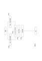
- FIG. 2 is a functional block diagram of an OCC transmitter and an OCC receiver according to an embodiment.
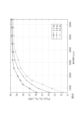
- a comparison of rate loss for different distribution matching schemes. A comparison of rate losses among MPDM, EMPDM, 2p-EMPDM, and 4p-EMPDM.
- Functional block diagram of the 4p-EMPDM dimmer and codebook structure diagram. A diagram showing the codebook structures of MPDM, EMPDM, and 4p-EMPDM.
- a diagram showing the binary tree structure of 4p-EMPDM. 4 is a diagram for explaining details of the flow of digital signal processing in an OCC transmitter and an OCC receiver according to an embodiment.
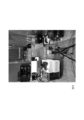
- FIG. Photograph of the low-speed RoI signaling-high-speed OCC demonstration system showing the OCC transmitter, low-speed camera, and video monitor.
- a photo of the low-speed RoI signaling-high-speed OCC demonstration system showing the OCC transmitter, high-speed camera, and OCC receiver.
- the relationship between exposure time and pixel Eb/N 0 was measured by changing the distance between the transmitter and receiver.
- FIG. 1 shows two-class classification using intensity domain thresholding.
- FIG. 4 is a flowchart illustrating the operation of the OCC transmitter 1.
- FIG. 4 is a flowchart illustrating the operation of the OCC receiver 2.
- FIG. 2 is a diagram showing an example of the functional configuration of a computer.
- the disclosed technology provides binary extended multiset-partition distribution matching (EMPDM) with four composition pairs (4p), and a dimmer based on 4p-EMPDM for visible light RoI signaling applications.
- EPDM binary extended multiset-partition distribution matching
- ⁇ will have a slightly different value than PA(1).
- LPS Layered Probabilistic Shaping
- SPE systematic polar encoder
- the 4p-EMPDM dimmer shapes the information word ⁇ such that the proportion of logical 1s and logical 0s is not significantly different. As a result, the run length of y is limited to the range that does not cause flicker at the minimum optical clock rate.
- the frequency of occurrence of logic 1 and logic 0 in codeword u (e.g., "1011101011” has “three 0s and seven 1s") is called a "composition.”
- a composition with a frequency of occurrence of logic 1 i is represented as ⁇ i .
- the sequence "1011101011” belongs to ⁇ 7 .
- a low-speed global shutter camera with a frame rate of 30 fps and long exposure time detects the dimming level of a Light Emission Diode (LED), which decodes the logic 0s and 1s in a low-rate bitstream that is used for RoI identification.
- the high-speed camera decodes the high-rate data stream on the RoI detected by the low-speed camera at a high frame rate (e.g., 10,000 fps).
- the SD successive canceling SPD decodes the codeword y' into u'.
- the inverse 4p-EMPDM dimmer decodes the message u' to reconstruct the high-speed binary sequence ⁇ ', assuming that all transmission errors have been corrected by SD-SPD.
- the modulation technique chosen was OOK due to its simplicity and popularity in the VLC system. Since the code word u is a combination of a low-rate signal and a high-rate signal, the code word u and the code word u' before decoding (inverse dimming) are sometimes referred to as "superimposed signals" in this specification.
- the matching rate R DM which indicates how many bits of information are transmitted with each bit coded in binary DM, is defined by the following equation (1). where is an inequality Then, the largest k that satisfies is output.
- CCDM Constant Composition Distribution Matching
- MPDM was introduced as a method to reduce rate loss, especially for short block lengths, and is suitable for practical implementation (Non-Patent Document 4).
- the rate loss reduction of MPDM comes from the inclusion of multiple Composition Pairs (CPs) in addition to a Typical Composition (TC) to generate a non-fixed composition DM.
- CPs Composition Pairs
- TC Typical Composition
- the compositions used in a pair are complementary to each other, such that the probabilistic average of the sequences generated by both compositions achieves the desired distribution.
- Non-Patent Document 4 introduced a binary tree structure in which each information word is divided into a payload that is mapped to a binary CCDM sequence and a prefix that selects the composition.
- MPDM which requires the sequence number of a particular composition to be rounded to the nearest power of 2 (power of 2 constraint)
- the disclosed technology proposes binary EMPDM, which lifts the power of 2 constraint for each composition and extends the codebook of conventional matching.
- EMPDM which lifts the power of 2 constraint for each composition and extends the codebook of conventional matching.
- Cm represents a binary group of n elements of weight m, forming the codebook of TC.
- C i denote the number of elements in C i
- the number of permutations in the codebook of composition pairs ⁇ m ⁇ l , ⁇ m+l ⁇ (l>0) can be calculated as follows:
- the total number of permutations in the EMPDM codebook including TC and all CPs is given by:
- the rate loss of EMPDM, ⁇ EMPDM is estimated by replacing R EMPDM in equation (10) with R DM in equation (4).
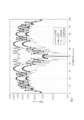
- FIG. 11 shows the rate loss for several examples of MPDM and EMPDM, including codebooks with TC and two leading CPs (2p-EMPDM), four leading CPs (4p-EMPDM), and all CPs (EMPDM).
- 4p-EMPDM is a compact version of EMPDM that generates only run-length aware codewords (codewords with a maximum run-length bounded to a predefined value) for the purpose of reducing flicker in VLC applications.
- Arrow 31 shows the empirical shaping range for low-level dimming (logic 0) and arrow 32 shows the empirical shaping range for high-level dimming (logic 1).
- the run-length-aware shaping range for VLC applications is marked with a shaded box. Comparing EMPDM in Figure 2 with 4p-EMPDM in Figure 3, we can see that the rate loss of 4p-EMPDM is equivalent to that of EMPDM. In particular, there is no difference in the range of PA(1) ⁇ 45% at low level dimming and in the range of PA(1)>55% at high level dimming.
- the rate loss of 2p-EMPDM increases as a penalty for not including the third and fourth CPs in the codebook.
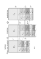
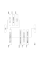
- FIG 4 shows a detailed functional block diagram and codebook structure of the 4p-EMPDM dimmer 11 in Figure 1.
- EPDM Extended MPDM
- FIG. 5 shows the codebook structures of conventional MPDM, EMPDM, and 4p-EMPDM.
- EMPDM is an extension of the MPDM codebook because its composition codebook does not have a power-of-two constraint.
- the 4p-EMPDM codebook has a binary tree structure, and adjacent compositions share the codebook.
- the 4p-EMPDM codebook contains only four CPs in addition to the TC. This is because the size of the codebook for the remaining CPs is not significant compared to the size of the codebook for the four CPs.
- the total number of output sequences of the two-level 4p-EMPDM dimmer is however, represents a function that rounds to the nearest power of two.
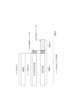
- Figure 6 shows the binary tree structure of 4p-EMPDM.
- a Huffman code is used to determine the prefix that identifies the subset pair.
- the first p l bits (1 or 2 bits) are used for the prefix.
- the next bit (the first bit of the payload) selects the shared subset in the subset pair.
- the prefix and the first bit of the payload are sometimes collectively referred to as the "selection code.”
- Shared exemplar-pairwise subset The codebook of a TC is shared with the codebook of its paired composition element, e.g., the subset with (C m , C m ⁇ 1 ) and (C m , C m+1 ).
- shared Pairwise Subsets A codebook is shared between two pairs of composition elements, e.g., the subsets with (Cm -1 , Cm -2 ), (Cm +1 , Cm +2 ), (Cm -2 , Cm -3 , Cm -4 ), and (Cm +2 , Cm +3 , Cm +4 ).
- Each subset of leaf nodes applies binary CCDM based on m-out-of-n codes to map the remaining kl- bit payload one-to-one to a shaped sequence.
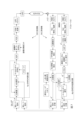
- the OCC transmitter 1 includes a dimmer 11 (4p-EMPDM dimmer), an FEC encoding unit 12 (systematic polar encoding unit), an OOK modulation unit 13, and an LED 14.
- a dimmer 11 (4p-EMPDM dimmer)
- FEC encoding unit 12 systematic polar encoding unit
- OOK modulation unit 13 an LED 14.
- the low rate signal v and the high rate signal ⁇ are input to the dimmer 11 (steps S1801 and S1802). Based on the low-rate signal and the high-rate signal, the dimmer 11 converts the high-rate signal into an m-out-of-n code using the codebook, and outputs a superimposed signal (step S1803).
- the FEC encoder 12 encodes the superimposed signal using, for example, a systematic polar code, and outputs an FEC code (step S1804).
- the OOK modulator 13 modulates the FEC code to drive the LED 14 and output an OCC signal (step S1805).
- the OCC receiver 2 includes a low-speed camera 21, a high-speed camera 22, an RoI identifying unit 23, an OOK demodulating unit 24, an FEC decoding unit 25 (systematic polar decoding unit), and an inverse dimmer 26 (4p-EMPDM inverse dimmer).
- the low-speed camera 21 captures the entire camera field of view and outputs it to the RoI identifying unit 23 (step S1901).
- the RoI identifying unit 23 detects a low rate signal from the camera's field of view (step S1902).
- the RoI identifying unit 23 identifies the RoI in the field of view from the detected low-rate signal (step S1903), and outputs the RoI information to the high-speed camera 22. Based on the RoI information, the high-speed camera 22 extracts the RoI portion from the imaging signal (camera field of view) and outputs the RoI imaging signal (step S1904).
- the OOK demodulation unit 24 demodulates the RoI imaging signal and outputs the FEC code (step S1905).
- the FEC decoding unit 25 decodes the superimposed signal from the FEC code (step S1906).
- the inverse dimmer 26 decodes the high-rate signal from the superimposed signal using the m-out-of-n encoding codebook generated in the same manner as the dimmer 11 (step S1907).
- FIG. 7 shows the flow of digital signal processing (DSP) for the proposed transmitter and receiver, and the experimental setup. 8 and 9 show the low-rate RoI signaling-high-rate OCC demonstration system.
- FIG. 17 summarizes the setup of the low-rate and high-rate experimental systems.
- the low-rate RoI signal receiver used a 30 fps low-speed global-shutter camera to detect the dimming level and decode the low-rate bitstream.
- An Atmos Shogun 7 with SSD mini-storage served as the video capture and monitoring device.
- VLC transmitters with low-power LEDs were placed at distances of 1.7 m, 2.9 m, and 4.2 m from the receiver.
- HS camera/OCC Receiver high-speed camera receiver
- FPGA field programmable gate array
- noise affects image quality has been widely studied in the literature.
- the impact of noise varies from one imaging system to another.
- noise is modeled as a Gaussian distribution.
- the main noise sources are thermal noise generated by the readout circuitry and shot noise due to background illumination.
- the variance of the shot noise is proportional to the area of the received pixel and the received light intensity.
- CMOS complementary metal-oxide semiconductor
- N 0 the noise density
- E b the bit energy
- a the mark and space amplitude
- ⁇ and ⁇ fitting parameters.
- a camera with a long exposure time can be considered as a low-pass filter that attenuates high-frequency signals. Therefore, adjusting the exposure time has a large effect on pixel Eb/N 0 .
- pixel Eb/ N0 changes with the exposure time of the CMOS camera.
- Te exceeds 4500 ⁇ s
- pixel Eb/ N0 saturates at about 39.7dB at distances of 1.7m, 2.9m, and 4.2m.
- Te 6400 ⁇ s.
- pixel Eb/ N0 is 39.74dB.
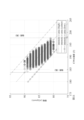
- Figure 11 shows how noise affects the intensity I and area A of a 50% dimming symbol.
- a low threshold, a median threshold, and a high threshold are used to determine a threshold range, which is the range between a low threshold and a high threshold.
- the within-class variance due to noise effects determines the width of the range.
- the threshold range is defined to avoid ambiguity in detecting close dimming levels.
- the median threshold is given by the following equation (14): where s and b represent the slope and y-intercept of the threshold line, respectively, and can be calculated using the following equations (15) and (16). where A and I represent the area (width ⁇ height) and average intensity of the captured pixels, respectively.
- the high and low threshold lines can be determined using a linear equation.
- b h and b l are determined by substituting the coordinates of the furthest points above and below the central threshold in equation (14).
- Two-class classification by intensity domain threshold is shown in Figure 13.
- the camera captures the dimming symbol shaped by the 4p-EMPDM dimmer.
- Both the intensity and area of a captured pixel are used to determine an intensity-area threshold.
- the camera-based receiver is placed 4.2 m away from the VLC transmitter.
- a typical shaping level is close to 50%; specifically, 30% to 41% is a logical 0 and 70% to 59% is a logical 1.
- the rate loss of the dimmer decreases from 0.031 to 0.0165 (Fig. 3), which means that the matching rate increases with the proposed area-intensity threshold.
- 4p-EMPDM Dimmer As explained in the section [4p-EMPDM Dimmer and Its Implementation Method], the 4p-EMPDM dimmer generates only sequences with no significant difference in the ratio of logic 0s and logic 1s. Therefore, compared to other binary distribution matching techniques, 4p-EMPDM is suitable for non-RLL VLC systems because the run length of its output sequence is constrained to mitigate flicker.
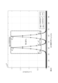
- Figure 15 shows the overhead of the 4p-EMPDM dimmer and FEC coding.
- the coding overhead is the ratio of the number of redundant bits to the number of information bits and can be expressed as a percentage.
- the overhead of 4p-EMPDM is 4.16%, and the overhead of SPE(FEC) is 28%.
- a low-rate logic level is created from two dimming levels, therefore, the power distributions of the LPS symbols corresponding to the two dimming levels must not overlap in order to be identified by a low-speed camera-based receiver.
- the program describing this processing can be recorded on a computer-readable recording medium.
- Examples of computer-readable recording media include magnetic recording devices, optical disks, magneto-optical recording media, and semiconductor memories.
- the program may be distributed, for example, by selling, transferring, or lending portable recording media such as DVDs or CD-ROMs on which the program is recorded. Furthermore, the program may be stored in a storage device of a server computer, and the program may be distributed by transferring the program from the server computer to other computers via a network.
- a computer that executes such a program for example, first stores in its own storage device the program recorded on a portable recording medium or the program transferred from a server computer. Then, when executing a process, the computer reads the program stored on its own recording medium and executes the process according to the read program. As another execution form of the program, the computer may read the program directly from the portable recording medium and execute the process according to the program, or may execute the process according to the received program each time a program is transferred from the server computer to the computer.
- the above-mentioned process may also be executed by a so-called ASP (Application Service Provider) type service that does not transfer the program from the server computer to the computer, but realizes the processing function only by issuing an execution instruction and obtaining the results.
- ASP Application Service Provider
- the program in this form includes information used for processing by an electronic computer that is equivalent to a program (such as data that is not a direct command to the computer but has properties that specify the processing of the computer).
- the device is configured by executing a specific program on a computer, but at least a portion of the processing may be realized by hardware.
Landscapes
- Physics & Mathematics (AREA)
- Electromagnetism (AREA)
- Engineering & Computer Science (AREA)
- Computer Networks & Wireless Communication (AREA)
- Signal Processing (AREA)
- Optical Communication System (AREA)
Abstract
Description
開示技術は、光学カメラ通信のための調光制御と符号化技術に関する。 The disclosed technology relates to dimming control and encoding technology for optical camera communication.
光学カメラ通信(optical camera communication: OCC)とは、送信手段として、例えば、LEDディスプレイの光源を用い、受信手段としてカメラを用いる可視光通信のことである。送信側は、LEDなどの光源が発する光を変調してデジタル信号を送信する。変調は、光源のONとOFFの制御により行う。 Optical camera communication (OCC) is a visible light communication method that uses a light source, such as an LED display, as the transmitting means and a camera as the receiving means. The transmitting side transmits a digital signal by modulating the light emitted by a light source such as an LED. Modulation is performed by controlling the light source to be turned on and off.
IEEE 802.15.7 mグループ (TG 7 m)により、可視光関心領域(Region-of-Interest: RoI)信号が車両OCCシステムに導入された(非特許文献1)。この技術により、OCCシステムは低レートと高レートのデータストリームを同時に送信できるようになった。
The IEEE 802.15.7m group (
低レートストリームがRoI識別に使用される場合、高レートストリームは選択されたRoI上の高速データ通信に使用される。トゥインクル・可変パルス位置変調(Variable Pulse Position Modulation: VPPM)や、ハイブリッド空間位相シフトキーイング(Hybrid Spatial Phase-Shift Keying: HS-PSK)などのハイブリッド変調方式が、低レートストリームおよび高レートストリームの変調でよく利用される。 While the low-rate stream is used for RoI identification, the high-rate stream is used for high-speed data communication over the selected RoI. Hybrid modulation schemes such as Twinkle Variable Pulse Position Modulation (VPPM) and Hybrid Spatial Phase-Shift Keying (HS-PSK) are often used to modulate the low-rate and high-rate streams.
具体的には、高レートストリームはトゥインクルVPPM(非特許文献2)、または調光空間8位相シフトキーイング(Dimming Spatial-8 Phase-Shift Keying: DS8-PSK)(非特許文献1)によって変調され、低レートストリームはアンダーサンプルド周波数シフトオンオフキーイング(Undersampled Frequency-Shift On-Off Keying: UFSOOK)、アンダーサンプルド位相シフトオンオフキーイング (Undersampled Phase-Shift On-Off Keying: UPSOOK)、または空間2位相シフトキーイング(Spatial-2 Phase-Shift Keying: S2-PSK)によって変調される。 Specifically, the high-rate stream is modulated by Twinkle VPPM (Non-Patent Document 2) or Dimming Spatial-8 Phase-Shift Keying (DS8-PSK) (Non-Patent Document 1), and the low-rate stream is modulated by Undersampled Frequency-Shift On-Off Keying (UFSOOK), Undersampled Phase-Shift On-Off Keying (UPSOOK), or Spatial-2 Phase-Shift Keying (S2-PSK).
RoIから送信された両方のストリームはデュアルカメラ受信機でデコードされ、高速(high-speed: HS)カメラが高レートストリームを復調し、低速(low-speed: LS) カメラが低レートストリームを復調する。この結果、高速カメラベースの受信機の計算負荷が軽減される。 Both streams transmitted from the RoI are decoded by the dual-camera receiver, where the high-speed (HS) camera demodulates the high-rate stream and the low-speed (LS) camera demodulates the low-rate stream. This reduces the computational load on the high-speed camera-based receiver.
調光制御は、OCCや可視光通信(visible light communication: VLC)システムにおける重要な問題の一つである。
従来のアプローチでは、調光制御には補正シンボルの挿入とパンクチャリングを使用する。すると、フレームに多数の冗長ビットが追加されるため、達成可能な伝送レートが低下する。
Dimming control is one of the key issues in OCC and visible light communication (VLC) systems.
Traditional approaches use correction symbol insertion and puncturing for dimming control, which adds a large number of redundant bits to the frame, reducing the achievable transmission rate.
調光レベルは、光ビットストリームのOFF(以下「論理0」とする)またはON(以下「論理1」とする)の割合を0%から100%の間で調整することで管理できる。HS-PSKおよびトゥインクルVPPMにおける調光制御では、高レートパルス群のデューティサイクル(ONまたはOFFの長さ)を変更する。そのため、各光パルスを厳格なタイミングで同期し、サンプリングし、復号しなければならないDS8-PSK信号やトゥインクルVPPM信号では、復調が容易でない。
The dimming level can be managed by adjusting the proportion of the optical bit stream that is OFF (hereafter referred to as "
さらに、従来のVLCシステムでは、長く続く論理1や論理0は避けるべきものだった。ちらつき問題やクロック・データ・リカバリ(clock data recovery: CDR)問題の原因となるからである。このため、限定ラン・レングス(run-length-limited: RLL)符号は、各シンボルにおける論理1と論理0の数を等しくして、直流(direct current: DC)のバランスを保つ。 Furthermore, in traditional VLC systems, long sequences of logical 1s or 0s are to be avoided because they cause flicker and clock data recovery (CDR) problems. For this reason, run-length-limited (RLL) codes maintain direct current (DC) balance by having an equal number of logical 1s and logical 0s in each symbol.
マンチェスターや4B6Bや8B10BなどのRLL符号におけるレート損失と実装の容易さの間にはトレード・オフの関係がある。
さらに、前方誤り訂正(forward error correction: FEC)について見ると、FECとRLLを共用するシステムでは、硬判定(hard-decision: HD)方式のFECデコーダしかサポートされていない。ほとんどのRLLデコーダがハード出力情報を生成するためであり、この結果、エラー訂正のパフォーマンスが低下する。
There is a trade-off between rate loss and ease of implementation in RLL codes such as Manchester, 4B6B, and 8B10B.
Furthermore, when it comes to forward error correction (FEC), systems that use both FEC and RLL only support hard-decision (HD) FEC decoders, as most RLL decoders generate hard output information, which results in poor error correction performance.
キムらによって導入されたソフト入力ソフト出力(soft-input soft-output: SISO)のRLLデコーダは、軟判定(soft-decision: SD)FEC復号アルゴリズム用のソフト出力を生成してシステムの信頼性を向上させている。しかし、SISO RLL符号の復号アルゴリズムは複雑であり、VLC受信機に組み込むことは不可能である。 The soft-input soft-output (SISO) RLL decoder introduced by Kim et al. improves system reliability by generating soft outputs for the soft-decision (SD) FEC decoding algorithm. However, the decoding algorithm for SISO RLL codes is complex and cannot be integrated into the VLC receiver.
上述の欠点を有するハイブリッド変調技術を使用する代わりに、Nguyenらは、RoIシグナリングアプリケーションのための確率的整形を提案したが(非特許文献3)、実装にはまだ課題がある。 Instead of using hybrid modulation techniques with the drawbacks mentioned above, Nguyen et al. proposed probabilistic shaping for RoI signaling applications (Non-Patent Document 3), but implementation remains challenging.
上記課題を解決するため、開示技術に係るOCC送信機は、調光器と、オン・オフ・キーイング変調部とを備える。
調光器は、低レート信号に基づいて高レート信号をm-out-of-n符号化により変換し、所望の2つの調光レベルを与える重畳信号を生成する。
m-out-of-n符号化のmとnは、2つの調光レベルをそれぞれΥ0、Υ1とし、m=Υ0n、m=Υ1nの関係にある。
m-out-of-n符号化のコードブックは、nビット中にm個の論理1または論理0を有するビットシーケンスの集合をCmとして、前記Cmと、Cm-lとCm+lのペア(lは自然数)とを用いて生成する。
オン・オフ・キーイング変調部は、調光器の出力した信号を光信号に変換する。
また、OCC送信機が送信するOCC信号を受信する、開示技術に係るOCC受信機は、低速カメラと、RoI特定部と、高速カメラと、オン・オフ・キーイング復調部と、逆調光器とを備える。
低速カメラは、OCC信号を撮影して低レート信号を出力する。
RoI特定部は、低レート信号からRoIを特定する。
高速カメラは、カメラ視野の中からRoIを切り出してRoI撮影信号を出力する。
オン・オフ・キーイング復調部は、RoI撮影信号を復調し、重畳信号を取得する。
逆調光器は、コードブックを用いて重畳信号から高レート信号を復号する。
In order to solve the above problem, an OCC transmitter according to the disclosed technology includes a dimmer and an on-off keying modulation unit.
The dimmer converts the high-rate signal based on the low-rate signal using m-out-of-n encoding to generate a superimposed signal that provides the two desired dimming levels.
The m and n in the m-out-of-n coding are expressed as m=Y0n, m=Y1n, where Y0 and Y1 are the two dimming levels, respectively.
A codebook for m-out-of-n encoding is generated using a set of bit sequences Cm having m logical 1s or logical 0s in n bits, and pairs Cm-l and Cm+l (l is a natural number).
The on-off keying modulator converts the signal output from the dimmer into an optical signal.
In addition, an OCC receiver according to the disclosed technology, which receives an OCC signal transmitted by an OCC transmitter, includes a low-speed camera, an RoI identification unit, a high-speed camera, an on-off keying demodulation unit, and an inverse dimmer.
The low-speed camera captures the OCC signal and outputs a low-rate signal.
The RoI determination unit determines the RoI from the low rate signal.
The high-speed camera extracts the RoI from the camera's field of view and outputs an RoI shooting signal.
The on-off keying demodulation unit demodulates the RoI imaging signal to obtain a superimposed signal.
The inverse dimmer uses a codebook to decode the high rate signal from the superimposed signal.
非RLL機能のおかげで、ソフトディシジョン前方誤り訂正アルゴリズムを適用することができ、これによりシステムの信頼性を高めることができる。
開示技術の4p‐EMDPM調光器に基づく可視光RoI信号技術は、従来のトゥインクルVPPMアプローチと比較して容易なクロック追跡と同期を可能にする。
開示技術の4p‐EMDPM法は、従来法よりも確率的整形によるレート損失(ビット冗長性)を低減する。
Thanks to the non-RLL feature, soft-decision forward error correction algorithms can be applied, which increases the reliability of the system.
The disclosed 4p-EMDPM dimmer-based visible light RoI signaling technique enables easier clock tracking and synchronization compared to the conventional twinkle VPPM approach.
The disclosed 4p-EMDPM method reduces rate loss (bit redundancy) due to probabilistic shaping more than conventional methods.
以下、開示技術の実施形態について、詳細に説明する。なお、同じ機能を有する構成部には同じ番号を付し、重複説明を省略する。 Below, an embodiment of the disclosed technology will be described in detail. Components having the same functions will be given the same numbers, and duplicate explanations will be omitted.
開示技術は、4つのコンポジションペア(Four Composition Pairs: 4p)を持つバイナリ拡張マルチセット-パーティション分布マッチング(binary extended Mutiset-Parttion Distribution Matching: EMPDM)、および可視光RoI信号アプリケーションのための4p-EMPDMに基づく調光器を提供する。最初に、4p-EMPDMが使用される提案されたシステムの概要を通じて開示技術を説明し、その後、提案されたアルゴリズムの理論的分析と、RoIシグナリングアプリケーション専用の4p-EMPDM調光器の最適パラメータを見つけるための実験的最適化を行う。 The disclosed technology provides binary extended multiset-partition distribution matching (EMPDM) with four composition pairs (4p), and a dimmer based on 4p-EMPDM for visible light RoI signaling applications. We first explain the disclosed technology through an overview of the proposed system in which 4p-EMPDM is used, followed by a theoretical analysis of the proposed algorithm and an experimental optimization to find the optimal parameters of a 4p-EMPDM dimmer dedicated for RoI signaling applications.
[提案システムの概要]
提案システムの機能ブロック図を図1に示す。システムへの2つの入力は、低レート信号vと、高レート信号μ=(μ1,μ2,...,μk)である。なお、vとμj(1≦j≦k)は、0または1の値を取るものとする。
nビットの4p-EMPDM調光符号語uと、zビットのFEC符号語yにおける論理1の割合を、それぞれ、type PA(1)(%)とω(%)とする。OCC送信機では、4p-EMPDM調光器は、ベルヌーイ(1/2)分布を持つ情報語μを、任意の分布を持つ符号語u=(u1, u2,..., un)に符号化する。
[Outline of the proposed system]
The functional block diagram of the proposed system is shown in Figure 1. The two inputs to the system are a low-rate signal v and a high-rate signal μ = (μ 1 , μ 2 , ..., μ k ), where v and μ j (1≦j≦k) take the
Let the proportion of logic 1s in an n-
実は、メッセージuが、組織的FECエンコーダによってエンコードされると、ωはPA(1)とわずかに異なる値となる。階層型確率的シェーピング(Layered Probabilistic Shaping: LPS) アーキテクチャに従い、組織的ポーラーエンコーダ(Systematic Polar Encoder: SPE)を使用してωの確率的形状を保持し、非RLL VLC送信機で2つの調光レベルを生成する。さらに、従来のVLCシステムのようにRLL符号を使用してラン・レングスを制限するのではなく、4p-EMPDM調光器は情報語μを、論理1と論理0の出現割合に大きな差が生じないように整形する。この結果、yのラン・レングスは、最小光学クロックレートでちらつきが発生しない範囲に制限される。
なお、符号語uにおける論理1と論理0の出現頻度(例えば、"1011101011"では「0が3回、1が7回」)を、本明細書において「コンポジション」と呼ぶ。また、論理1の出現頻度がiのコンポジションをγiで表す。例えば、シーケンス"1011101011"はγ7に属する。
In fact, when the message u is encoded by a systematic FEC encoder, ω will have a slightly different value than PA(1). Following the Layered Probabilistic Shaping (LPS) architecture, we use a systematic polar encoder (SPE) to preserve the probabilistic shape of ω and generate two dimming levels in the non-RLL VLC transmitter. Furthermore, instead of using an RLL code to limit the run length as in traditional VLC systems, the 4p-EMPDM dimmer shapes the information word μ such that the proportion of logical 1s and logical 0s is not significantly different. As a result, the run length of y is limited to the range that does not cause flicker at the minimum optical clock rate.
In this specification, the frequency of occurrence of
デュアルカメラ受信機(OCC受信機)では、フレームレート30 fps、長露光時間の低速グローバルシャッターカメラが、発光ダイオード(Light Emission Diode: LED)の調光レベルを検出する。このカメラが、RoI識別に使用される低レートビットストリームの論理0,1をデコードする。
高速カメラは、高フレームレート(例えば10000 fps)で、低速カメラが検出したRoI上の高レートデータストリームをデコードする。SD連続キャンセルSPD (SD-SPD) は、符号語y'をu'に復号する。最後に、逆4p-EMPDM調光器は、伝送エラーはすべてSD-SPDによって修正されているという想定で、メッセージu'をデコードして、高速バイナリシーケンスμ'を再構築する。
In the dual camera receiver (OCC receiver), a low-speed global shutter camera with a frame rate of 30 fps and long exposure time detects the dimming level of a Light Emission Diode (LED), which decodes the logic 0s and 1s in a low-rate bitstream that is used for RoI identification.
The high-speed camera decodes the high-rate data stream on the RoI detected by the low-speed camera at a high frame rate (e.g., 10,000 fps). The SD successive canceling SPD (SD-SPD) decodes the codeword y' into u'. Finally, the inverse 4p-EMPDM dimmer decodes the message u' to reconstruct the high-speed binary sequence μ', assuming that all transmission errors have been corrected by SD-SPD.
その単純さとVLCシステムにおける人気の高さから、変調技術にはOOKを選択した。
なお、符号語uは、低レート信号と高レート信号とが合成されたものなので、本明細書では、符号語uおよびデコード(逆調光)前の符号語u'を「重畳信号」と称することもある。
The modulation technique chosen was OOK due to its simplicity and popularity in the VLC system.
Since the code word u is a combination of a low-rate signal and a high-rate signal, the code word u and the code word u' before decoding (inverse dimming) are sometimes referred to as "superimposed signals" in this specification.
[バイナリ拡張MPDM(EMPDM)]
バイナリDMで符号化された各ビットで何ビットの情報が伝送されるかを示すマッチングレートRDMは、次の式(1)で定義される。



The matching rate R DM , which indicates how many bits of information are transmitted with each bit coded in binary DM, is defined by the following equation (1).
アルファベットB={0,1}、タイプPAの離散確率変数Aのエントロピーは式(2)で与えられる。



固定コンポジション分布マッチング(Constant Composition Distribution Matching: CCDM)のレート損失は、ブロック長が短くなると増加する(参考文献1)。 The rate loss of Constant Composition Distribution Matching (CCDM) increases as the block length decreases (Reference 1).
参考文献1:P. Schulte et al., "Constant composition distribution matching", IEEE Trans. Inf. Theory, vol. 62, no. 1, pp.430 - 434, Jan. 2016. Reference 1: P. Schulte et al., "Constant composition distribution matching", IEEE Trans. Inf. Theory, vol. 62, no. 1, pp.430 - 434, Jan. 2016.
MPDMは、レート損失を減らす方法(特にブロック長が短い場合に)として導入され、実用的な実装に適している(非特許文献4)。MPDMのレート損失低減は、非固定コンポジションDMを生成するために、典型コンポジション(Typical Composition: TC)に加えて、複数のコンポジションペア(Composition Pairs: CPs)を含めることに起因している。ペアで使用されるコンポジションは、各構成コンポジションが、両コンポジションで生成したシーケンスの確率的平均が目的の分布を達成するような、互いに相補的なコンポジションとなっている。 MPDM was introduced as a method to reduce rate loss, especially for short block lengths, and is suitable for practical implementation (Non-Patent Document 4). The rate loss reduction of MPDM comes from the inclusion of multiple Composition Pairs (CPs) in addition to a Typical Composition (TC) to generate a non-fixed composition DM. The compositions used in a pair are complementary to each other, such that the probabilistic average of the sequences generated by both compositions achieves the desired distribution.
非特許文献4は、各情報語が、バイナリCCDMシーケンスにマッピングされるペイロードと、コンポジションを選択するプレフィックスとに分割される二分木構造を導入した。
特定のコンポジションのシーケンス数を最も近い2のべき乗に丸める必要(2のべき乗制約)がある従来のMPDMとは異なり、開示技術では、各コンポジションの2のべき乗制約を解除して、従来のマッチングのコードブックを拡張するバイナリEMPDMを提案する。また、EMPDMを二分木構造で実装可能にするために、TCと先頭CPの間で、および隣接コンポジション間で、コードブックを共有することを提案する。
Unlike conventional MPDM, which requires the sequence number of a particular composition to be rounded to the nearest power of 2 (power of 2 constraint), the disclosed technology proposes binary EMPDM, which lifts the power of 2 constraint for each composition and extends the codebook of conventional matching. In addition, to make EMPDM implementable with a binary tree structure, we propose sharing the codebook between the TC and the top CP, and between adjacent compositions.
Cmは、重みmのn要素のバイナリ群を表し、TCのコードブックを形成する。低レベル調光の場合、m=Υ0・n、高レベル調光の場合m=Υ1・nである。|Ci|がCiの要素数を表すものとして、コンポジションペア {γm-l, γm+l}(l>0)のコードブック内の順列の数は次のように計算できる。


Υ0<0.5の場合、min(|Cm-l|,|Cm+l|)=|Cm-l|であり、式(5)、(6)より



EMPDMは、固定長の逆転可能なマッピングであるため、入力ビット数kと出力シーケンス長nは固定されている。制約Υ0=1-Υ1を課すと、Rolシグナリングアプリケーションのために2つの対称シェーピングレベルをサポートする実装につながる。この制約を式(9)に課すことで、次式が得られる。

(1)と(9)から、2つのシェーピングレベルにおけるEMPDMのマッチングレートは次のように書ける。

EMPDMのレート損失ΔEMPDMは、式(10)のREMPDMを、式(4)のRDMに置き換えることによって推定される。図2は異なる分布マッチング方式のレート損失を示す。シーケンスは、1%から99%の異なる出力分布PA(1)についてシェーピングされている。
EMPDMのレート損失は、すべての出力分布に対して他のシェーピング方法のレート損失よりもはるかに低いことが見て取れる。さらに、Υ0=1-Υ1という制約の下で、レート損失はPA(1)=50%に関して対称である。マッチングレートとレート損失の対称性は、同じレート損失で2つの調光レベルを可能にするDMベースの調光器を設計する上で重要である。
The rate loss of EMPDM, Δ EMPDM , is estimated by replacing R EMPDM in equation (10) with R DM in equation (4). Figure 2 shows the rate loss of different distribution matching schemes. The sequences are shaped for different power distributions PA(1) from 1% to 99%.
It can be seen that the rate loss of EMPDM is much lower than that of other shaping methods for all power distributions. Moreover, under the constraint Υ 0 = 1 - Υ 1 , the rate loss is symmetric with respect to PA(1) = 50%. The symmetry of the matching rate and rate loss is important in designing a DM-based dimmer that allows two dimming levels with the same rate loss.
ここで、EMPDMコードブックにすべてのCPが含まれている場合、ルックアップテーブル (Look up tables: LUTs)を使用してEMPDMを実装することは困難であるように思われる。さらに、非RLL VLCシステムではちらつきが根本的な問題であるため、論理1または0の長いフリーランを持つ整形シーケンスは避ける必要がある。そこで、開示技術の以降の説明では、EMPDMを最適化して、VLCベースのRoIシグナリングアプリケーションと互換性を持たせる。 Now, it appears that implementing EMPDM using look up tables (LUTs) would be difficult if the EMPDM codebook contained all CPs. Furthermore, since flicker is a fundamental problem in non-RLL VLC systems, shaped sequences with long free runs of logical 1s or 0s need to be avoided. Therefore, the remainder of the disclosed technique optimizes EMPDM to make it compatible with VLC-based RoI signaling applications.
[4p-EMPDM調光器とその実装方法]
RoIシグナリングアプリケーションのために、2つの調光レベルΥ0とΥ1をサポートする4p-EMPDM調光器を提案する。ここで、Υ0とΥ1はそれぞれ、低レートストリームの論理0と論理1のための調光器の典型出力分布である。
1≦m<nとして、CmがCm-1より何倍大きいかを見るため、次式を計算する。

For RoI signaling applications, we propose a 4p-EMPDM dimmer that supports two dimming levels , Υ0 and Υ1 , where Υ0 and Υ1 are the typical power distributions of the dimmer for
Assuming that 1≦m<n, to see how many times larger C m is than C m-1 , calculate the following formula.
<例> n=100の場合、C25はC20より452.5倍大きく、C15より957293倍大きい。つまり、C15<<C20<<C25である。 <Example> When n=100, C25 is 452.5 times larger than C20 and 957293 times larger than C15 . In other words, C15 << C20 << C25 .
式(11)によれば、EMPDMコードブックの不均一シーケンスのほとんどは、TC(γm)と主要なCP{γm-l, γm+l}を持つ。なお、lは小さな正の値である。
図3に、MPDMと、EMPDMのいくつかの例について、レート損失を示す。EMPDMの例は、コードブックがTCと、2つの先頭CPを持つ場合(2p-EMPDM)、4つの先頭CPを持つ場合(4p-EMPDM)、そしてすべてのCPを持つ場合(EMPDM)である。
4p-EMPDMはEMPDMのコンパクトバージョンであり、VLCアプリケーションでちらつきを軽減する目的で、ラン・レングスを意識した符号語(ラン・レングスの最大値を所定の値に抑えた符号語)のみを生成する。矢印31は低レベル調光(論理0)の、矢印32は高レベル調光(論理1)の、経験的なシェーピング範囲を示している。
According to equation (11), most of the nonuniform sequences in the EMPDM codebook have TC(γ m ) and dominant CP{γ m−l , γ m+l }, where l is a small positive value.
Figure 3 shows the rate loss for several examples of MPDM and EMPDM, including codebooks with TC and two leading CPs (2p-EMPDM), four leading CPs (4p-EMPDM), and all CPs (EMPDM).
4p-EMPDM is a compact version of EMPDM that generates only run-length aware codewords (codewords with a maximum run-length bounded to a predefined value) for the purpose of reducing flicker in VLC applications.
PA(1)=50%前後のギャップは、低レート信号の論理0と論理1の状態検出が不明確にならないように設けた。VLCアプリケーションのラン・レングスを意識したシェーピング範囲(ランレングス意識レンジ)は囲み斜線でマークされている。図2のEMPDMと図3の4p-EMPDMとを見比べると、4p-EMPDMのレート損失はEMPDMと同等であることがわかる。特に、低レベル調光ではPA(1)<45%の範囲で、高レベル調光ではPA(1)>55%の範囲で、遜色がない。
The gap around PA(1)=50% is provided to ensure that detection of the
一方、2p-EMPDMのレート損失は、コードブックに3番目と4番目のCPを含めないことのペナルティとして、増加する。非RLL VLCシステムで、符号語は、論理1と論理0の出現割合に大きな差が生じないように整形する必要がある。2つの調光レベルを50%付近(例えばΥ0=41%、Υ1=59%)とすれば、論理1と論理0の出現割合にはあまり差がないはずである。したがって、最も低いレート損失とDCバランスが、4p-EMPDM調光器の制約されたシェーピング範囲を決定するための2つの基準となる。実験的評価を行い、2つのラン・レングスを意識した整形範囲を決定した。37%<PA(1)<45%と、55%<PA(1)<63%である(図3を参照)。
On the other hand, the rate loss of 2p-EMPDM increases as a penalty for not including the third and fourth CPs in the codebook. In a non-RLL VLC system, the codeword needs to be shaped so that there is no significant difference between the occurrence ratios of
図4に、図1の4p-EMPDM調光器11の詳細機能ブロック図と、コードブック構造を示す。4p-EMPDM調光器は、[バイナリ拡張MPDM(EMPDM)]の項で説明したように、タイプPA(1)=50%に関する対称性を通じて、同じレート損失で2つの調光レベルをサポートする。
低レベル4p-EMPDM調光部41と高レベル4p-EMPDM調光部42は、調光レベルΥ0、Υ1から定まるmに従ってそれぞれ、コンポジションペア(Cm-l, Cm+l)(ただしl={1、2、3、4})のコードブックと、典型コンポジション(Cm)のコードブックを利用し、そのレート損失はCCDMよりも小さい。
Figure 4 shows a detailed functional block diagram and codebook structure of the 4p-
The low-
図5は、従来のMPDM、EMPDM、および4p-EMPDMのコードブック構造を示している。4p-EMPDMは、典型コンポジションγmと4つのコンポジションペア{γm-l,γm+l}(l={1, 2, 3, 4})を備えた、EMPDMのコンパクト版である。EMPDMがMPDMのコードブックの拡張であるというのは、[バイナリ拡張MPDM(EMPDM)]の項で説明した通り、そのコンポジションのコードブックには2のべき乗制約がないためである。4p-EMPDMのコードブックは二分木構造を持ち、隣接するコンポジションでコードブックを共有する。また、4p-EMPDMのコードブックは、TCの他に4つのCPのみを含む。残りのCPのコードブックのサイズは、前記4つのCPのコードブックのサイズと比較して重要でないからである。 Figure 5 shows the codebook structures of conventional MPDM, EMPDM, and 4p-EMPDM. 4p-EMPDM is a compact version of EMPDM with a typical composition γ m and four composition pairs {γ m-l , γ m+l } (l={1, 2, 3, 4}). As explained in [Binary Extended MPDM (EMPDM)], EMPDM is an extension of the MPDM codebook because its composition codebook does not have a power-of-two constraint. The 4p-EMPDM codebook has a binary tree structure, and adjacent compositions share the codebook. In addition, the 4p-EMPDM codebook contains only four CPs in addition to the TC. This is because the size of the codebook for the remaining CPs is not significant compared to the size of the codebook for the four CPs.
(7)と(8)から、2レベル4p-EMPDM調光器の出力シーケンスの総数は次のようになる。


図6に4p-EMPDMの二分木構造を示す。サブセットペアを識別するプレフィックスを決定するため、ハフマンコードが使用される。最初のplビット(1ビットまたは2ビット)はプレフィックスに用いる。次のビット(ペイロードの先頭ビット)は、サブセットペア内の共有サブセットを選択する。なお、本明細書では、プレフィックスとペイロードの先頭ビットをまとめて「選択符号」と称することがある。 Figure 6 shows the binary tree structure of 4p-EMPDM. A Huffman code is used to determine the prefix that identifies the subset pair. The first p l bits (1 or 2 bits) are used for the prefix. The next bit (the first bit of the payload) selects the shared subset in the subset pair. In this specification, the prefix and the first bit of the payload are sometimes collectively referred to as the "selection code."
共有サブセットには2種類ある。
(i)シェアド・典型-ペアワイズ・サブセット
TCのコードブックが、ペアを成すコンポジション要素のコードブックと共有される。例えば、(Cm, Cm-1)と(Cm, Cm+1) を備えたサブセットである。
(ii)シェアド・ペアワイズ・サブセット
コードブックが、2個のペアを成すコンポジション要素間で共有される。例えば、(Cm-1, Cm-2),(Cm+1, Cm+2),(Cm-2,Cm-3,Cm-4),および(Cm+2,Cm+3,Cm+4)を備えたサブセットである。リーフノードの各サブセットにより、残りのklビットペイロードを整形シーケンスに1対1マッピングするため、m-out-of-n符号に基づくバイナリCCDMが適用される。
There are two types of shared subsets.
(i) Shared exemplar-pairwise subset: The codebook of a TC is shared with the codebook of its paired composition element, e.g., the subset with (C m , C m−1 ) and (C m , C m+1 ).
(ii) Shared Pairwise Subsets: A codebook is shared between two pairs of composition elements, e.g., the subsets with (Cm -1 , Cm -2 ), (Cm +1 , Cm +2 ), (Cm -2 , Cm -3 , Cm -4 ), and (Cm +2 , Cm +3 , Cm +4 ). Each subset of leaf nodes applies binary CCDM based on m-out-of-n codes to map the remaining kl- bit payload one-to-one to a shaped sequence.
[OCC送信機]
ここで、図1と図18を用いて、開示技術のOCC送信機とその動作について説明する。
OCC送信機1は、調光器11(4p-EMPDM調光器)、FEC符号部12(組織的polar符号部)、OOK変調部13、LED14を備える。
あらかじめ2つの調光レベルΥ0、Υ1を定め、調光レベルΥ0ではm=Υ0n、調光レベルΥ1ではm=Υ1nとして、Cmと、Cm-lとCm+lのペア(l=1,2,3,4)とからm-out-of-n符号化のコードブックを作成する。
調光器11に、低レート信号vと、高レート信号μが入力される(ステップS1801、S1802)。
調光器11は、低レート信号と高レート信号に基づき、コードブックを用いて高レート信号をm-out-of-n符号で変換して重畳信号を出力する(ステップS1803)。
FEC符号化部12は、例えば組織的ポーラー符号で重畳信号を符号化し、FEC符号を出力する(ステップS1804)。
OOK変調器13は、FEC符号を変調してLED14を駆動し、OCC信号を出力する(ステップS1805)。
[OCC transmitter]
Here, the OCC transmitter of the disclosed technology and its operation will be described with reference to FIG. 1 and FIG.
The
Two dimming levels Υ 0 and Υ 1 are defined in advance, and m = Υ 0 n at dimming level Υ 0 and m = Υ 1 n at dimming level Υ 1. A codebook for m-out-of-n encoding is created from C m and pairs of C m-l and C m+l (l = 1, 2, 3, 4).
The low rate signal v and the high rate signal μ are input to the dimmer 11 (steps S1801 and S1802).
Based on the low-rate signal and the high-rate signal, the dimmer 11 converts the high-rate signal into an m-out-of-n code using the codebook, and outputs a superimposed signal (step S1803).
The
The
[OCC受信機]
続いて、図1と図19を用いて、開示技術のOCC受信機とその動作について説明する。
OCC受信機2は、低速カメラ21、高速カメラ22、RoI特定部23、OOK復調部24、FEC復号部25(組織的polar復号部)、逆調光器26(4p-EMPDM逆調光器)を備える。
低速カメラ21でカメラ視野全体を撮影し、RoI特定部23に出力する(ステップS1901)。
RoI特定部23は、カメラ視野から低レート信号を検出する(ステップS1902)。
RoI特定部23は、検出した低レート信号から、視野中のRoIを特定し(ステップS1903)、RoI情報を高速カメラ22に出力する。
高速カメラ22は、RoI情報に基づき、撮影信号(カメラ視野)からRoI部分を切り出してRoI撮影信号を出力する(ステップS1904)。
OOK復調部24は、RoI撮影信号を復調し、FEC符号を出力する(ステップS1905)。
FEC復号部25は、FEC符号から、重畳信号を復号する(ステップS1906)。
逆調光器26は、調光器11と同様に生成したm-out-of-n符号化コードブックを用いて、重畳信号から高レート信号を復号する(ステップS1907)。
[OCC receiver]
Next, the OCC receiver of the disclosed technology and its operation will be described with reference to FIG. 1 and FIG.
The
The low-
The
The
Based on the RoI information, the high-
The
The
The
4p-EMPDM調光器のコードブック構築と、その二分木構造の構築の詳細は、次の通りである。
1:2つの所望の調光レベルを生成する出力分布Υ0,Υ1を求める。
2:各調光レベルの典型コンポジションγmを求める。低レベル調光の場合はm=Υ0・n、高レベル調光の場合はm=Υ1・n。低レート信号vが調光レベルを決定する。
3:制約{γm-1,γm+1}=2{γm}(ただしl>0)を満たす、すべてのCPを求める。
4:コンポジションペア(Cm-l,Cm+l)のうち大きい方に含まれる、選択されていないシーケンスを削除する。この削除後のシーケンス数は|(Cm-l,Cm+l)|=2・min (|Cm-l|,|Cm+l|)となる。ただしl={1,2,3,4}。
5:主たるコードブックを、TCと4つのCPに限定する。コードブック中のシーケンスの総数は下記式で与えられる。

7:シーケンスの総数を、シーケンス総数を超えない最も近い2のべき乗(2k)の値に丸める。ここで、kは調光器の入力ビット数である。
8:シーケンス総数が2k個のコードブックを、大きさを変えて分割してサブセットのペアに割り当てる。例えば、シェアド・典型-ペアワイズ・サブセットに2のki乗個を、シェアド・ペアワイズ・サブセットに2のki+1乗個を割り当てる(図5、図6を参照)。
9:サブセットのペアを識別するため、plビットをプレフィックスビットとして予約する。プレフィックスビットの次のビットは、ペア内のサブセットを識別するために使用される。
(i)シェアド・典型-ペアワイズ・サブセットの場合:pl=1
(ii)シェアド・ペアワイズ・サブセットの場合:pl=2
10:m-out-of-nコードを使用して、klビットペイロードを、各サブセット内のシェイプされたシーケンスにマップする。
The details of the codebook construction of the 4p-EMPDM dimmer and the construction of its binary tree structure are as follows.
1: Find the output distributions Υ 0 , Υ 1 that produce the two desired dimming levels.
2: Calculate the typical composition γ m for each dimming level. For low-level dimming, m = Υ 0 · n, and for high-level dimming, m = Υ 1 · n. The low-rate signal v determines the dimming level.
3: Find all CPs that satisfy the constraint {γ m-1 , γ m+1 }=2{γ m } (where l>0).
4: Delete the unselected sequences in the larger of the composition pairs (C m-l , C m+l ). After this deletion, the number of sequences is |(C m-l , C m+l )|=2・min(|C m-l |, |C m+l |), where l={1, 2, 3, 4}.
5: The main codebook is restricted to TC and four CPs. The total number of sequences in the codebook is given by
7: Round the total number of sequences to the nearest power of two (2 k ) that does not exceed the total number of sequences, where k is the number of input bits of the dimmer.
8: A codebook with a total of 2k sequences is divided into subset pairs of varying sizes. For example, 2k i sequences are assigned to the shared typical-pairwise subset, and 2k i+1 sequences are assigned to the shared pairwise subset (see Figures 5 and 6).
9: To identify a pair of subsets, p l bits are reserved as prefix bits. The bit next to the prefix bit is used to identify the subset within the pair.
(i) Shared representativeness - pairwise subset case: p l =1
(ii) For shared pairwise subsets: p l =2
10: Use an m-out-of-n code to map the k l -bit payload to a shaped sequence in each subset.
[実験的最適化]
本節では実験的評価により4p-EMPDM調光器の整形レベルを最適化する方法を示す。このシステムは、Rolシグナリングアプリケーションの低レート通信の、論理0レベルと論理1レベルを表す2つの調光レベルをサポートする。調光器が出力分布PA(1)を変えるたびに、LEDの調光レベルはその変化を反映する。低速カメラベースの受信機は、調光レベルを検出することにより、RoIを識別する低レートストリームをデコードする。
[Experimental optimization]
In this section, we present a method to optimize the shaping level of the 4p-EMPDM dimmer through experimental evaluation. The system supports two dimming levels, representing
実験的最適化では、調光器の最適な整形レベルを見つけるための3つの基準がある。
(1)レート損失が、最も低いこと。
(2)出力分布が、非RLL VLCのラン・レングスを意識した範囲内であること(図3を参照)。
(3)対応する調光レベルが、低速カメラベースの受信機で容易に検出・復調できること。
In experimental optimization, there are three criteria for finding the optimal shaping level of the dimmer:
(1) The rate loss is the lowest.
(2) The output distribution is within a range that takes into account the run length of non-RLL VLC (see Figure 3).
(3) The corresponding dimming levels can be easily detected and demodulated by a low-speed camera-based receiver.
図7に、提案した送信機と受信機の、デジタル信号処理(Digital Signal Processing: DSP)の流れと実験装置を示す。
図8と図9に、低速RoIシグナリング-高速OCC実証システムを示す。
図17に、低レート実験システムと高レート実験システムの設定をまとめた。
低レートのRoI信号受信機には、調光レベルを検出し、低レートのビットストリームをデコードする、30fpsの低速グローバルシャッターカメラ(LS global-shutter camera)を使用した。SSDミニストレージ付きアトモス・ショーグン7は、ビデオキャプチャおよび監視デバイス(Video monitor)として機能する。低電力LEDを備えたVLC送信機(Transmitter)は、受信機から1.7 m、2.9 m、および4.2 mの距離に配置される。
FIG. 7 shows the flow of digital signal processing (DSP) for the proposed transmitter and receiver, and the experimental setup.
8 and 9 show the low-rate RoI signaling-high-rate OCC demonstration system.
FIG. 17 summarizes the setup of the low-rate and high-rate experimental systems.
The low-rate RoI signal receiver used a 30 fps low-speed global-shutter camera to detect the dimming level and decode the low-rate bitstream. An
一方で、10000 fps、露出50μsで動作する高速カメラ受信機(HS camera/OCC Receiver)を使用する。高速カメラによって撮影された画像は、フィールドプログラマブルゲートアレイ(FPGA)に送って処理する。また、提案した方法の性能を評価するために、OCCチャネル上に高速OCCシステムのシミュレーションシステムを構築した。 On the other hand, we use a high-speed camera receiver (HS camera/OCC Receiver) that operates at 10,000 fps with an exposure time of 50 μs. Images captured by the high-speed camera are sent to a field programmable gate array (FPGA) for processing. In addition, to evaluate the performance of the proposed method, we built a simulation system of a high-speed OCC system on the OCC channel.
ノイズが画質にどのように影響するかは、文献で広く研究されている。一般に、ノイズの影響はイメージングシステムによって異なる。OCCシステムでは、ノイズはガウス分布としてモデル化される。主なノイズ源は、読み出し回路によって発生する熱ノイズと、背景照明によるショットノイズである。ショットノイズの分散値は、受信したピクセルの面積と受信した光強度に比例する。電荷結合素子/相補型金属酸化物半導体 (CCD/CMOS) カメラのピクセルノイズは、1シンボルあたり1ビットの前提で、次のように近似できる。

非特許文献1で実験的に推定したα=0.01529とβ=0.1973を用いて、pixel Eb/N0を計算した。また、露光時間の長いカメラは、高周波信号を減衰させるローパスフィルターと考えることができる。そのため、露光時間を調整するとpixel Eb/N0に大きく影響する。
How noise affects image quality has been widely studied in the literature. In general, the impact of noise varies from one imaging system to another. In OCC systems, noise is modeled as a Gaussian distribution. The main noise sources are thermal noise generated by the readout circuitry and shot noise due to background illumination. The variance of the shot noise is proportional to the area of the received pixel and the received light intensity. The pixel noise of a charge-coupled device/complementary metal-oxide semiconductor (CCD/CMOS) camera can be approximated as follows, assuming one bit per symbol:
Pixel Eb/N 0 was calculated using α = 0.01529 and β = 0.1973, which were experimentally estimated in
図10に示した通り、CMOSカメラの露光時間によってpixel Eb/N0は変化する。しかしTeが4500μsを超えると、1.7 m、2.9 m、4.2 mの各距離で、pixel Eb/N0は約39.7dBで飽和する。20 kHzのTx クロックレートでは、128ビットフレームの平均輝度が、低速カメラで完全に感知されるには6.4 ms必要である。そこで、4p-EMPDM調光器の最適なシェーピングレベルを見つけるため、Te=6400μsに設定する。ことのとき、pixel Eb/N0は39.74 dBである。 As shown in Figure 10, pixel Eb/ N0 changes with the exposure time of the CMOS camera. However, when Te exceeds 4500μs, pixel Eb/ N0 saturates at about 39.7dB at distances of 1.7m, 2.9m, and 4.2m. With a Tx clock rate of 20kHz, the average luminance of a 128-bit frame requires 6.4ms to be fully sensed by the low-speed camera. Therefore, to find the optimal shaping level of the 4p-EMPDM dimmer, we set Te = 6400μs. Then, pixel Eb/ N0 is 39.74dB.
図11は、ノイズが50%調光シンボルの強度Iと領域Aにどのように影響するかを示す。強度分散|maxI-minI|として14.5、領域分散|maxA-minA|として10を得た。低レートのビットストリームを復調するためのしきい値範囲を決定するクラス内分散として、50%調光レベルでの分散を採用した。 Figure 11 shows how noise affects the intensity I and area A of a 50% dimming symbol. We obtain an intensity variance |maxI - minI| of 14.5 and an area variance |maxA - minA| of 10. We take the variance at the 50% dimming level as the within-class variance to determine the threshold range for demodulating the low-rate bitstream.
従来のOCCシステムは、強度のしきい値との比較によってLEDのオンとオフの状態を決定する。しきい値を決定するため、VLC送信機で30%<PA(1)<70%の、4p-EMPDM調光器で整形された10万個のシンボルを送信した。
図12は、論理0はΥ0=30%、論理1はΥ1=70%として調光器で整形された受信シンボルを示す。論理0/論理1判定のしきい値を決定するには強度情報のみが利用される。
カメラセンサーの露光時間はTe=6400μsである。カメラベースの受信機は、VLC送信機から4.2 m離れた場所に配置した。Υ1=70%の調光器で整形されたシンボルのピクセル強度は大きく変化しないことがわかる。受信機は、異なるコンポジションで整形されたシンボルについてピクセル領域の違いのみを検出できる。
Conventional OCC systems determine the LED on/off state by comparing the intensity to a threshold. To determine the threshold, the VLC transmitter transmits 100,000 symbols shaped by a 4p-EMPDM dimmer with 30%<PA(1)<70%.
12 shows the received symbols shaped by the dimmer with Υ 0 =30% for
The exposure time of the camera sensor is Te = 6400 μs. The camera-based receiver is placed 4.2 m away from the VLC transmitter. It can be seen that the pixel intensities of the symbols shaped with a dimmer of Υ1 = 70% do not change significantly. The receiver can only detect the difference in pixel area for the symbols shaped with different compositions.
一方、Υ0=30%の調光器で整形されたシンボルでは、強度のばらつきがかなり大きい。その理由は、70%に近い調光レベルでは、ピクセル強度が飽和に達するためである。VPPMはこの調光レベルで最高の性能を示すことが確認された(非特許文献1)。
この発見は、ピクセル強度に加えて、受信信号のピクセル領域がデータの復調に有用であることを明らかにした。したがって、我々の低速カメラベースの受信機は、データの復調としきい値の決定に、キャプチャされた信号の強度と領域情報を使用する。
On the other hand, the symbols shaped with a dimmer of Υ 0 = 30% show a much larger variation in intensity, because the pixel intensity reaches saturation at dimming levels close to 70%, and VPPM has been found to perform best at this dimming level (Non-Patent Document 1).
This finding revealed that in addition to pixel intensity, the pixel area of the received signal is useful for data demodulation. Therefore, our low-speed camera-based receiver uses the intensity and area information of the captured signal for data demodulation and threshold determination.
具体的には、低いしきい値と高いしきい値の間の範囲であるしきい値範囲を決定するために、低いしきい値、中央しきい値、高いしきい値を使用する。ノイズ効果によるクラス内分散値が、レンジの幅を決める。しきい値範囲は、近接した調光レベルを検出する際のあいまいさを避けるために定義される。中心しきい値は次の式(14)となる。



しきい値の高い線と低い線は、直線方程式を使用して決定できる。


任意の点(Xi, Yi)が中心しきい値の上か下かを確認するには、その点の座標(Xi, Yi)をしきい値線方程式(14)に挿入する。そして、Yiをs.X+bと比較する。
もしYi<s.X+bならば、点は線の下にある。そうでなくてYi> s.X+bならば、点はしきい値より上にある。
To check whether any point (X i , Y i ) is above or below the central threshold, insert the coordinates (X i , Y i ) of that point into the threshold line equation (14), and compare Y i with s.X+b.
If Yi < s.X+b then the point is below the line, else if Yi > s.X+b then the point is above the threshold.
図13に、強度領域しきい値による二クラス分類を示す。カメラは、4p-EMPDM調光器で整形された調光シンボルを撮影する。典型整形割合は、論理0についてΥ0=41%、論理1についてΥ1=59%である。
キャプチャされたピクセルの強度と領域の両方が、強度-領域しきい値を決定するために使用される。カメラセンサーの露光時間はTe=6400μsである。カメラベースの受信機は、VLC送信機から4.2 m離れた場所に配置される。強度-領域しきい値を使用すると、典型整形レベルは50%に近くなる。具体的には、30%から41%が論理0、70%から59%が論理1である。
この結果、調光器のレート損失は0.031から0.0165に減少し(図3)、これはマッチングレートが提案された領域-強度しきい値と共に増加することを意味する。
Two-class classification by intensity domain threshold is shown in Figure 13. The camera captures the dimming symbol shaped by the 4p-EMPDM dimmer. The typical shaping percentages are Υ 0 = 41% for
Both the intensity and area of a captured pixel are used to determine an intensity-area threshold. The exposure time of the camera sensor is T e =6400 μs. The camera-based receiver is placed 4.2 m away from the VLC transmitter. Using the intensity-area threshold, a typical shaping level is close to 50%; specifically, 30% to 41% is a logical 0 and 70% to 59% is a logical 1.
As a result, the rate loss of the dimmer decreases from 0.031 to 0.0165 (Fig. 3), which means that the matching rate increases with the proposed area-intensity threshold.
図14は、Υ0=41%、Υ1=59%の4p-EMPDMおよびEMPDM調光器のコードブックサイズを示している。これらの最適な出力分布は、低レートの論理レベルを決定するために強度-領域しきい値を使用して、実験的に決定された。TCと4つのCPにコードブックの大部分が属するため、4p-EMPDM調光器のコードブックサイズは、EMPDM調光器の90.88%であることがわかる。PA(1)=[37%,45%]とPA(1)=[55%,63%]のレンジでは、4p-EMPDM調光器のレート損失はEMPDM調光器のそれと同等である(図3)。[4p-EMPDM調光器とその実装方法]の項
で説明した通り、4p-EMPDM調光器は、論理0と論理1の比率に大きな差がないシーケンスのみを生成する。したがって、他のバイナリ分布マッチング手法と比較して、4p-EMPDMは、その出力シーケンスのラン・レングスが、ちらつきが緩和されるように制約されているため、非RLL VLCシステムに適している。
Figure 14 shows the codebook sizes of the 4p-EMPDM and EMPDM dimmers with Υ 0 = 41% and Υ 1 = 59%. These optimal power distributions were experimentally determined using intensity-area thresholds to determine the low-rate logic levels. As most of the codebook belongs to the TC and four CPs, the codebook size of the 4p-EMPDM dimmer is found to be 90.88% of that of the EMPDM dimmer. In the ranges of PA(1) = [37%, 45%] and PA(1) = [55%, 63%], the rate loss of the 4p-EMPDM dimmer is comparable to that of the EMPDM dimmer (Figure 3). As explained in the section [4p-EMPDM Dimmer and Its Implementation Method], the 4p-EMPDM dimmer generates only sequences with no significant difference in the ratio of logic 0s and logic 1s. Therefore, compared to other binary distribution matching techniques, 4p-EMPDM is suitable for non-RLL VLC systems because the run length of its output sequence is constrained to mitigate flicker.
図15に、4p-EMPDM調光器とFEC符号化のオーバーヘッドを示す。符号化オーバーヘッドは冗長ビット数と情報ビット数の比率であり、パーセントで表すことができる。4p-EMPDMのオーバーヘッドは4.16%、SPE(FEC)のオーバーヘッドは28%である。 Figure 15 shows the overhead of the 4p-EMPDM dimmer and FEC coding. The coding overhead is the ratio of the number of redundant bits to the number of information bits and can be expressed as a percentage. The overhead of 4p-EMPDM is 4.16%, and the overhead of SPE(FEC) is 28%.
組織的FECエンコーダは、非組織的FECエンコーダと比較して、4p-EMPDM調光器の出力確率分布をよりよく保存するが、組織的FECエンコーダのジェネレータおよびパリティ行列に対する論理演算は、通常、調光器の符号語の出力分布を変更する。そこで、モンテカルロシミュレーションでLPSの出力シーケンスの出力分布を調べた。図16は、4p-EMPDM調光器によって整形され、LPSアーキテクチャに従ったSPEによって符号化された10万個の情報語の出力確率分布を示している。SPEは調光器の出力分布をわずかにPA(1)=50%に近づけることが分かる。
Rolシグナリングアプリケーションの場合、低レートロジックレベルは2つの調光レベルから作成される。したがって、低速カメラベースの受信機で識別されるために、2つの調光レベルに対応するLPSシンボルの出力分布は重複してはならない。
Although the systematic FEC encoder better preserves the output probability distribution of the 4p-EMPDM dimmer compared with the non-systematic FEC encoder, the logical operations on the generator and parity matrix of the systematic FEC encoder usually change the output distribution of the dimmer codewords. Therefore, we investigated the output distribution of the output sequence of the LPS in a Monte Carlo simulation. Figure 16 shows the output probability distribution of 100,000 information words shaped by the 4p-EMPDM dimmer and encoded by the SPE according to the LPS architecture. It can be seen that the SPE slightly brings the output distribution of the dimmer closer to PA(1)=50%.
For Rol signaling applications, a low-rate logic level is created from two dimming levels, therefore, the power distributions of the LPS symbols corresponding to the two dimming levels must not overlap in order to be identified by a low-speed camera-based receiver.
[プログラム、記録媒体]
上述の各種の処理は、図20に示すコンピュータ2000の記録部2020に、上記方法の各ステップを実行させるプログラムを読み込ませ、制御部2010、入力部2030、出力部2040、表示部2050などに動作させることで実施できる。
[Program, recording medium]
The various processes described above can be implemented by loading a program that executes each step of the above method into the
この処理内容を記述したプログラムは、コンピュータで読み取り可能な記録媒体に記録しておくことができる。コンピュータで読み取り可能な記録媒体としては、例えば、磁気記録装置、光ディスク、光磁気記録媒体、半導体メモリ等どのようなものでもよい。 The program describing this processing can be recorded on a computer-readable recording medium. Examples of computer-readable recording media include magnetic recording devices, optical disks, magneto-optical recording media, and semiconductor memories.
また、このプログラムの流通は、例えば、そのプログラムを記録したDVD、CD-ROM等の可搬型記録媒体を販売、譲渡、貸与等することによって行う。さらに、このプログラムをサーバコンピュータの記憶装置に格納しておき、ネットワークを介して、サーバコンピュータから他のコンピュータにそのプログラムを転送することにより、このプログラムを流通させる構成としてもよい。 The program may be distributed, for example, by selling, transferring, or lending portable recording media such as DVDs or CD-ROMs on which the program is recorded. Furthermore, the program may be stored in a storage device of a server computer, and the program may be distributed by transferring the program from the server computer to other computers via a network.
このようなプログラムを実行するコンピュータは、例えば、まず、可搬型記録媒体に記録されたプログラムもしくはサーバコンピュータから転送されたプログラムを、一旦、自己の記憶装置に格納する。そして、処理の実行時、このコンピュータは、自己の記録媒体に格納されたプログラムを読み取り、読み取ったプログラムに従った処理を実行する。また、このプログラムの別の実行形態として、コンピュータが可搬型記録媒体から直接プログラムを読み取り、そのプログラムに従った処理を実行することとしてもよく、さらに、このコンピュータにサーバコンピュータからプログラムが転送されるたびに、逐次、受け取ったプログラムに従った処理を実行することとしてもよい。また、サーバコンピュータから、このコンピュータへのプログラムの転送は行わず、その実行指示と結果取得のみによって処理機能を実現する、いわゆるASP(Application Service Provider)型のサービスによって、上述の処理を実行する構成としてもよい。なお、本形態におけるプログラムには、電子計算機による処理の用に供する情報であってプログラムに準ずるもの(コンピュータに対する直接の指令ではないがコンピュータの処理を規定する性質を有するデータ等)を含むものとする。 A computer that executes such a program, for example, first stores in its own storage device the program recorded on a portable recording medium or the program transferred from a server computer. Then, when executing a process, the computer reads the program stored on its own recording medium and executes the process according to the read program. As another execution form of the program, the computer may read the program directly from the portable recording medium and execute the process according to the program, or may execute the process according to the received program each time a program is transferred from the server computer to the computer. The above-mentioned process may also be executed by a so-called ASP (Application Service Provider) type service that does not transfer the program from the server computer to the computer, but realizes the processing function only by issuing an execution instruction and obtaining the results. Note that the program in this form includes information used for processing by an electronic computer that is equivalent to a program (such as data that is not a direct command to the computer but has properties that specify the processing of the computer).
また、この形態では、コンピュータ上で所定のプログラムを実行させることにより、本装置を構成することとしたが、これらの処理内容の少なくとも一部をハードウェア的に実現することとしてもよい。 In addition, in this embodiment, the device is configured by executing a specific program on a computer, but at least a portion of the processing may be realized by hardware.
1 OCC送信機
11 調光器
12 FEC符号化部
13 OOK変調部
14 LED
15 記憶部
2 OCC受信機
21 低速カメラ
22 高速カメラ
23 RoI特定部
24 OOK復調部
25 FEC復号部
26 逆調光器
27 記憶部
2000 コンピュータ
2010 制御部
2020 記録部
2030 入力部
2040 出力部
2050 表示部
1
15
Claims (9)
低レート信号に基づいて高レート信号をm-out-of-n符号化により変換し、所望の2つの調光レベルを与える重畳信号を生成する調光器と、
前記調光器の出力した信号を光信号に変換するオン・オフ・キーイング変調部と、を含み、
前記調光器は、前記2つの調光レベルをそれぞれΥ0、Υ1とし、調光レベルΥ0ではm=Υ0n、調光レベルΥ1ではm=Υ1nとして、前記高レート信号をm-out-of-n符号化で変換してnビット信号を出力するものであり、
nビット中にm個の論理1または論理0を有するビットシーケンスの集合をCmとして、前記m-out-of-n符号化のコードブックは、Cmと、Cm-lとCm+lのペア(lは、m<n/2のとき最大でm、m>n/2のとき最大でn-mの自然数)とを用いて生成したものである
OCC送信機。 An OCC transmitter that generates an OCC signal in which a low rate signal and a high rate signal are superimposed,
a dimmer that converts a high-rate signal based on a low-rate signal by m-out-of-n encoding to generate a superimposed signal that provides two desired dimming levels;
an on-off keying modulation unit that converts the signal output by the dimmer into an optical signal;
the dimmer converts the high-rate signal by m-out-of-n coding to output an n-bit signal, with the two dimming levels being Υ 0 and Υ 1 , respectively , and with m = Υ 0 n at the dimming level Υ 0 and m = Υ 1 n at the dimming level Υ 1;
An OCC transmitter in which Cm is a set of bit sequences having m logical 1s or logical 0s in n bits, and the m-out-of-n encoding codebook is generated using Cm and pairs of Cm-l and Cm+l (l is a natural number up to m when m<n/2, and up to nm when m>n/2).
低レート信号に基づいて高レート信号をm-out-of-n符号化により変換し、所望の2つの調光レベルを与える重畳信号を生成する調光器と、
前記調光器の出力した信号を光信号に変換するオン・オフ・キーイング変調部と、を含み、
前記調光器は、前記2つの調光レベルをそれぞれΥ0、Υ1とし、調光レベルΥ0ではm=Υ0n、調光レベルΥ1ではm=Υ1nとして、前記高レート信号をm-out-of-n符号化で変換してnビット信号を出力するものであり、
nビット中にm個の論理1または論理0を有するビットシーケンスの集合をCmとして、前記m-out-of-n符号化のコードブックは、Cmと、Cm-lとCm+lのペア(l=1,2,3,4)とを用いて生成したものである
OCC送信機。 An OCC transmitter that generates an OCC signal in which a low rate signal and a high rate signal are superimposed,
a dimmer that converts a high-rate signal based on a low-rate signal by m-out-of-n encoding to generate a superimposed signal that provides two desired dimming levels;
an on-off keying modulation unit that converts the signal output by the dimmer into an optical signal;
the dimmer converts the high-rate signal by m-out-of-n coding to output an n-bit signal, with the two dimming levels being Υ 0 and Υ 1 , respectively , and with m = Υ 0 n at the dimming level Υ 0 and m = Υ 1 n at the dimming level Υ 1;
An OCC transmitter in which Cm is a set of bit sequences having m logical 1s or logical 0s in n bits, and the codebook for the m-out-of-n encoding is generated using Cm and pairs of Cm-l and Cm+l (l = 1, 2, 3, 4).
前記コードブックは、CmとCm-1とCm+1から一つのコードブックCB0、Cm-1とCm-2から一つのコードブックCB100、Cm+1とCm+2から一つのコードブックCB101、Cm-2とCm-3とCm-4から一つのコードブックCB110、Cm+2とCm+3とCm+4から一つのコードブックCB111として作成したものである、
OCC送信機。 3. The OCC transmitter of claim 2,
The codebooks are created as follows: one codebook CB0 is created from Cm, Cm-1, and Cm+1; one codebook CB100 is created from Cm-1 and Cm-2; one codebook CB101 is created from Cm+1 and Cm+2; one codebook CB110 is created from Cm-2, Cm-3, and Cm-4; and one codebook CB111 is created from Cm+2, Cm+3, and Cm+4.
OCC transmitter.
前記高レート信号は前記コードブックを選択するための選択符号を持ち、
前記調光器は、前記選択符号が0のとき前記コードブックCB0を選択し、100のとき前記コードブックCB100を選択し、101のとき前記コードブックCB101を選択し、110のとき前記コードブックCB110を選択し、111のとき前記コードブックCB111を選択する、
OCC送信機。 4. The OCC transmitter of claim 3,
the high rate signal has a selection code for selecting the codebook;
The dimmer selects the codebook CB0 when the selection code is 0, selects the codebook CB100 when the selection code is 100, selects the codebook CB101 when the selection code is 101, selects the codebook CB110 when the selection code is 110, and selects the codebook CB111 when the selection code is 111.
OCC transmitter.
低速カメラと、
RoI特定部と、
高速カメラと、
OOK復調部と、
逆調光器と、を含み、
前記RoI特定部は、前記低速カメラから前記低レート信号を得てRoIを特定し、
前記高速カメラは、カメラ視野の中から前記RoIを切り出してRoI撮影信号を出力し、
前記OOK復調部は、前記RoI撮影信号から前記重畳信号を取得し、
前記逆調光器は、前記コードブックを用いて前記重畳信号から前記高レート信号を復号する
OCC受信機。 2. An OCC receiver that receives an OCC signal generated by the OCC transmitter according to claim 1 and decodes the OCC signal into a low-rate signal and a high-rate signal,
A slow-speed camera
An RoI identification unit;
High-speed cameras and
An OOK demodulator;
an inverse dimmer;
The RoI determination unit obtains the low rate signal from the low speed camera and determines an RoI;
The high-speed camera extracts the RoI from the camera field of view and outputs an RoI imaging signal;
The OOK demodulation unit acquires the superimposed signal from the RoI imaging signal,
The inverse dimmer decodes the high rate signal from the superimposed signal using the codebook.
nビット中にm個の論理1を有するビットシーケンスの集合をCmとして、調光器がCmと、Cm-lとCm+lのペア(lは、m<n/2のとき最大でm、m>n/2のとき最大でn-mの自然数)とを用いてm-out-of-n符号化のコードブックを生成するステップと、
前記調光器が、前記2つの調光レベルをΥ0、Υ1とし、調光レベルΥ0ではm=Υ0n、調光レベルΥ1ではm=Υ1nとして、kビット信号をm-out-of-n符号化で変換して重畳信号を生成するステップと、
オン・オフ・キーイング変調部が、前記調光器の出力する信号を光信号に変換するステップと、
を含むOCC信号生成方法。 1. A method for generating an OCC signal having two dimming levels in which a low rate signal and a high rate signal are superimposed, comprising:
A step of generating an m-out-of-n encoding codebook by the dimmer using C m and pairs of C m-l and C m+l (l is a natural number up to m when m<n/2, and up to nm when m>n/2), where C m is a set of bit sequences having m logical 1s among n bits;
The dimmer converts the k-bit signal into an m-out-of-n coding format, where the two dimming levels are Υ 0 and Υ 1 , and m=Υ 0 n for the dimming level Υ 0 and m=Υ 1 n for the dimming level Υ 1, to generate a superposition signal;
An on-off keying modulation unit converts a signal output from the dimmer into an optical signal;
The OCC signal generating method includes:
低速カメラがOCC信号を撮影して低レート信号を出力するステップと、
RoI特定部が、前記低レート信号からRoIを特定するステップと、
高速カメラが、カメラ視野の中から前記RoIを切り出してRoI撮影信号を出力するステップと、
OOK復調部が、前記RoI撮影信号を復調し、前記重畳信号を取得するステップと、
逆調光器が、前記コードブックを用いて前記重畳信号から前記高レート信号を復号するステップと、
を含むOCC信号受信方法。 7. An OCC signal receiving method for receiving an OCC signal generated by the OCC signal generating method according to claim 6 and decoding a high-rate signal, comprising the steps of:
A low-speed camera captures the OCC signal and outputs a low-rate signal;
A step of an RoI determination unit determining an RoI from the low rate signal;
A step in which a high-speed camera extracts the RoI from a camera field of view and outputs an RoI imaging signal;
an OOK demodulation unit demodulating the RoI imaging signal to obtain the superimposed signal;
an inverse dimmer decoding the high rate signal from the superimposed signal using the codebook;
2. A method for receiving an OCC signal, comprising:
Priority Applications (2)
| Application Number | Priority Date | Filing Date | Title |
|---|---|---|---|
| JP2025541210A JPWO2025041258A1 (en) | 2023-08-22 | 2023-08-22 | |
| PCT/JP2023/030127 WO2025041258A1 (en) | 2023-08-22 | 2023-08-22 | Occ transmitter, occ receiver, occ signal generation method, occ signal reception method, and program |
Applications Claiming Priority (1)
| Application Number | Priority Date | Filing Date | Title |
|---|---|---|---|
| PCT/JP2023/030127 WO2025041258A1 (en) | 2023-08-22 | 2023-08-22 | Occ transmitter, occ receiver, occ signal generation method, occ signal reception method, and program |
Publications (1)
| Publication Number | Publication Date |
|---|---|
| WO2025041258A1 true WO2025041258A1 (en) | 2025-02-27 |
Family
ID=94731964
Family Applications (1)
| Application Number | Title | Priority Date | Filing Date |
|---|---|---|---|
| PCT/JP2023/030127 Pending WO2025041258A1 (en) | 2023-08-22 | 2023-08-22 | Occ transmitter, occ receiver, occ signal generation method, occ signal reception method, and program |
Country Status (2)
| Country | Link |
|---|---|
| JP (1) | JPWO2025041258A1 (en) |
| WO (1) | WO2025041258A1 (en) |
-
2023
- 2023-08-22 WO PCT/JP2023/030127 patent/WO2025041258A1/en active Pending
- 2023-08-22 JP JP2025541210A patent/JPWO2025041258A1/ja active Pending
Non-Patent Citations (3)
| Title |
|---|
| NGUYEN DUC-PHUC, SHIRAKI YOSHIFUMI, MURAMATSU JUN, MORIYA TAKEHIRO: "A Probabilistic Shaping Approach for Optical Region-of-Interest Signaling", IEEE PHOTONICS TECHNOLOGY LETTERS, IEEE, USA, vol. 34, no. 6, 15 March 2022 (2022-03-15), USA, pages 309 - 312, XP093282920, ISSN: 1041-1135, DOI: 10.1109/LPT.2022.3152798 * |
| NGUYEN PHUC DUC, SHIRAKI YOSHIFUMI, ISHIKAWA KENJI, MURAMATSU JUN, HARADA NOBORU, MORIYA TAKEHIRO: "Distribution Matching for Dimming Control in Visible-Light Region-of-Interest Signaling", IEEE PHOTONICS JOURNAL, IEEE, vol. 15, no. 1, 1 February 2023 (2023-02-01), pages 1 - 14, XP093282903, ISSN: 1943-0647, DOI: 10.1109/JPHOT.2022.3233092 * |
| THIEU MINH DUC; PHAM TUNG LAM; NGUYEN TRANG; JANG YEONG MIN: "Optical-RoI-Signaling for Vehicular Communications", IEEE ACCESS, IEEE, USA, vol. 7, 1 January 1900 (1900-01-01), USA , pages 69873 - 69891, XP011728958, DOI: 10.1109/ACCESS.2019.2918338 * |
Also Published As
| Publication number | Publication date |
|---|---|
| JPWO2025041258A1 (en) | 2025-02-27 |
Similar Documents
| Publication | Publication Date | Title |
|---|---|---|
| Mstafa et al. | A high payload video steganography algorithm in DWT domain based on BCH codes (15, 11) | |
| US20160359558A1 (en) | Signaling using idle period for coded light | |
| CN108292958A (en) | Light wireless communication technology | |
| Yang et al. | Boosting the throughput of LED-camera VLC via composite light emission | |
| CN107342814A (en) | A kind of neural net equalizer based on visible light communication | |
| He et al. | Artificial neural network-based scheme for 4-PWM OCC system | |
| CN112511226B (en) | Coding method for lighting, positioning and communication in visible light communication technology | |
| Deng et al. | MPPM based dimming control scheme in visible light communication systems | |
| Zuo et al. | Weight threshold check coding for dimmable indoor visible light communication systems | |
| CN114337933B (en) | SCMA-based high-speed visible light communication system and adaptive codec method | |
| CN111083078B (en) | Probability shaping quadrature amplitude modulation format blind identification method and system | |
| Otsuka et al. | Code synchronization in visible light communication system using dual orthogonal rolling shutter image sensors | |
| JP7175434B2 (en) | Transmission code processing device, transmission code processing method, and optical transmitter | |
| Nguyen et al. | Performance enhancement of optical camera communication system using optical camera communication coding and region‐of‐interest detection | |
| Nguyen et al. | Distribution matching for dimming control in visible-light region-of-Interest signaling | |
| Rêgo et al. | Frame recovery using multiple images in rolling shutter based systems | |
| CN207218702U (en) | A kind of visible light communication device based on universal CMOS camera | |
| US8437391B2 (en) | Transmitting video between two stations in a wireless network | |
| Zhan et al. | Megalight: Learning-based color adaptation for barcode stream recognition over screen-camera links | |
| Malathi et al. | Maximizing the embedding efficiency using linear block codes in spatial and transform domains | |
| CN115801124A (en) | PDM-SCMA-based visible light communication method and device | |
| Kim et al. | Zero reduction codes for efficient transmission and enhanced brightness in visible light communication | |
| Majumder et al. | Deep learning aided energy-efficient lossless video data transmission from IoVT visual sensors: P. Majumder et al. | |
| CN107947919B (en) | Compressed Sensing Correlation Imaging Encryption Method for Large Information Image Based on QR Code | |
| Kang et al. | Wide-angle visible light array communication based on intensity compressed single-pixel imaging |
Legal Events
| Date | Code | Title | Description |
|---|---|---|---|
| 121 | Ep: the epo has been informed by wipo that ep was designated in this application |
Ref document number: 23949719 Country of ref document: EP Kind code of ref document: A1 |
|
| ENP | Entry into the national phase |
Ref document number: 2025541210 Country of ref document: JP Kind code of ref document: A |
|
| WWE | Wipo information: entry into national phase |
Ref document number: 2025541210 Country of ref document: JP |
|
| NENP | Non-entry into the national phase |
Ref country code: DE |