WO2025041246A1 - Dispositif de commande électronique - Google Patents
Dispositif de commande électronique Download PDFInfo
- Publication number
- WO2025041246A1 WO2025041246A1 PCT/JP2023/030084 JP2023030084W WO2025041246A1 WO 2025041246 A1 WO2025041246 A1 WO 2025041246A1 JP 2023030084 W JP2023030084 W JP 2023030084W WO 2025041246 A1 WO2025041246 A1 WO 2025041246A1
- Authority
- WO
- WIPO (PCT)
- Prior art keywords
- housing
- electronic control
- glass coating
- control device
- coating layer
- Prior art date
- Legal status (The legal status is an assumption and is not a legal conclusion. Google has not performed a legal analysis and makes no representation as to the accuracy of the status listed.)
- Pending
Links
Images


Classifications
-
- H—ELECTRICITY
- H05—ELECTRIC TECHNIQUES NOT OTHERWISE PROVIDED FOR
- H05K—PRINTED CIRCUITS; CASINGS OR CONSTRUCTIONAL DETAILS OF ELECTRIC APPARATUS; MANUFACTURE OF ASSEMBLAGES OF ELECTRICAL COMPONENTS
- H05K5/00—Casings, cabinets or drawers for electric apparatus
- H05K5/06—Hermetically-sealed casings
Definitions
- This disclosure relates to an electronic control device.
- In-vehicle electronic control devices are required to have strict environmental resistance specifications against corrosion and deterioration, as well as a long lifespan.
- a long lifespan is required in environments where salt damage occurs, and a seal structure that prevents the progression of crevice corrosion is important.
- the size of electronic control devices is increasing, but there is a demand for inexpensive, high-quality products.
- pressure differences can occur inside electronic control devices due to altitude changes during air transport, etc., and a seal structure with extremely high pressure resistance of 50 kPa to 85 kPa may be required.
- Patent technology relating to sealing structures includes technology related to Patent Document 1.
- Patent Document 1 describes a storage case having a hollow case member and a lid portion that covers the hollow portion of the case member, in which a bonding thin film made of a silicone-based thin film or a carbon-based thin film is formed on the open end surface of the case member, and the sealing member and the case member are bonded via this bonding thin film, thereby ensuring the sealing structure of the storage case even in harsh environments where seawater (salt water) and the like may adhere to it.
- seawater seawater
- the housings of electronic control devices must be low-profile and lightweight, rather than large in size. This requires molding technology for the housings that maintain a thin wall while suppressing deformation, and because electronic components, not just aluminum electrolytic capacitors, need to be low-profile, the waterproof seal structure must also be low-profile.
- Patent Document 1 describes how to improve the bonding strength by bonding a bonding thin film, such as a silicone-based thin film or a carbon-based thin film, to a sealing member, but there is still room for improvement in obtaining sufficient bonding strength while achieving a low profile and low cost.
- a bonding thin film such as a silicone-based thin film or a carbon-based thin film
- the objective of this disclosure is to provide a compact electronic control device that has highly reliable airtightness and meets the increasingly stringent requirements for preventing salt damage.
- the electronic control device disclosed herein comprises a first housing and a second housing that house a circuit board, a glass coating layer formed on at least one of the first housing and the second housing, and a sealing member provided between the first housing and the second housing, and the glass coating layer is arranged so as to be in contact with the sealing member.
- FIG. 1 is an exploded perspective view showing an electronic control device according to a first embodiment
- 1 is a cross-sectional view of a main portion of an electronic control device according to a first embodiment
- FIG. 2 is a schematic cross-sectional view showing the chemical structure of the surface of a steel sheet before bonding in the first embodiment.
- FIG. 2 is a schematic cross-sectional view showing the chemical structure of the surface of the steel sheet after bonding in the first embodiment.
- FIG. 2 is a schematic cross-sectional view showing a glass coating layer in the first embodiment.
- 6 is a table showing an example of the measurement results of functional groups at each position of the glass coating layer of FIG. 5 .
- 1 is a graph showing the relationship between Si—O peak height and adhesive strength.
- FIG. 1 is a graph showing the relationship between C—H peak height and adhesive strength. 1 is a graph showing the relationship between O-H peak height and adhesive strength. 1 is a graph showing the relationship between the ratio of the C—H peak to the Si—O peak (relative C—H/Si—O ratio) and adhesive strength. 1 is a table showing the critical values of peak heights for each functional group. 4 is a graph showing an example of an analysis result of a steel sheet surface before bonding in the first embodiment.
- FIG. 2 is a schematic cross-sectional view showing the chemical structure of the surface of a steel sheet before bonding in a comparative example.
- FIG. 2 is a schematic cross-sectional view showing the chemical structure of the surface of a steel sheet after bonding in a comparative example.
- FIG. 11 is an exploded perspective view showing an electronic control device according to a second embodiment.
- FIG. 6 is a cross-sectional view of a main part of an electronic control device according to a second embodiment.
- FIG. 11 is a cross-sectional view of a main part of an electronic control device according to a third embodiment.
- FIG. 11 is a cross-sectional view of a main part of an electronic control device according to a fourth embodiment.
- FIG. 13 is a cross-sectional view of a main part of an electronic control device according to a fifth embodiment.
- FIG. 13 is a cross-sectional view of a main part of an electronic control device according to a sixth embodiment.
- FIG. 1 A first embodiment of an electronic control device according to the present disclosure will be described with reference to FIGS. 1 to 7.
- FIG. 1 A first embodiment of an electronic control device according to the present disclosure will be described with reference to FIGS. 1 to 7.
- FIG. 1 A first embodiment of an electronic control device according to the present disclosure will be described with reference to FIGS. 1 to 7.
- FIG. 1 A first embodiment of an electronic control device according to the present disclosure will be described with reference to FIGS. 1 to 7.
- FIG. 1 is an exploded perspective view showing an electronic control device according to the first embodiment. Note that, for convenience of illustration, electronic components mounted on a board are omitted from FIG. 1.
- the electronic control device 1 is composed of a printed wiring board 10 on which electronic components and the like are mounted, a first housing 20 (case), a second housing 30 (cover), a connector 60, sealing material 40, sealing material 41, screws 50, screws 51, etc.
- the printed wiring board 10 is an example of a circuit board, and the contents of this disclosure are not limited to printed wiring boards.
- the sealing materials 40 and 41 are also referred to as "sealing members.”
- the first housing 20, together with the second housing 30, houses the printed wiring board 10 inside and protects the printed wiring board 10 on which electronic components are mounted from water, foreign matter, and the like.
- the first housing 20 is preferably made of metal, and aluminum is preferable, in order to dissipate heat generated by the electronic components and to shield noise. In particular, when the electronic control device 1 is for a direct injection engine, a shielding effect is required.
- the first housing 20 is formed by an aluminum die-casting method using a mold.
- the material of the first housing 20 may be resin.
- the first housing 20 is formed by an injection molding method.
- the second housing 30 is fixed facing the first housing 20, and an internal space 11 (see FIG. 2) is formed between the first housing 20 and the second housing 30.
- a sealant 40 is sandwiched between the flange portion of the first housing 20 and the flange portion 31 of the second housing 30, so that the internal space 11 is sealed.
- the external dimensions of the electronic control unit 1 are preferably approximately 240 mm x 160 mm, which is relatively large for an electronic control unit to be placed in an engine room, with the shape of the top surface being roughly rectangular.
- Conventional electronic control units are usually approximately 160 mm x 160 mm in size, and the electronic control unit 1 of this embodiment is at least 1.5 times the size of such conventional products.
- the first housing 20 is provided with a through opening 21.
- the opening 21 is configured so that the connector 60 can pass through.
- the pressure inside the first housing 20 changes during transportation of the vehicle and in the environment in which it is used, such as changes in altitude and temperature. For this reason, the shape of the center of the first housing 20 changes the most.
- the center of the first housing 20 bulges outward when the internal pressure is high, and dents inward when the internal pressure is low. Therefore, it is preferable that the opening 21 is positioned closer to the periphery when viewed from the center of the first housing 20.
- Heat dissipation fins 25 are provided in the portions of the first housing 20 where no openings 21 are provided.
- the orientation of the heat dissipation fins 25 is parallel to the long sides of the first housing 20.
- the orientation of the heat dissipation fins 25 is not limited to this figure, and may be parallel to the short sides of the first housing 20. It is desirable that the orientation of the heat dissipation fins 25 be parallel to the flow of molten metal from the gate in aluminum die casting.
- the short side of the rectangular first housing 20 and the opposite side to the opening 21 is selected so that it is parallel to the longitudinal direction of the connector 60 and the heat dissipation fins 25, and the overflow position is set on the short side surface opposite the gate or on the side surface.
- the second gate is located on the long side of the rectangular first housing 20, and an overflow is provided on the opposite long side.
- the second gate position can improve the flow of the molten metal and reduce casting defects.
- Improved flow of the molten metal reduces air entrapment, eliminates aluminum die-cast defects such as voids and weld marks, reduces the amount of aluminum that flows to the overflow, and has the advantage of allowing molding at low cost. Poor flow of the molten metal and molding defects such as voids and weld marks can cause a decrease in thermal conductivity and cracks, which may affect the strength and appearance.
- the amount of deformation of the housing after molding becomes large, making it difficult to ensure flatness. In this case, the airtightness of the sealing material decreases, so it is desirable to use a material that can improve the flow of the molten metal.
- the first housing 20 is provided with a number of pedestals for fixing the printed wiring board 10. For example, pedestals are provided that are tapped for tightening the screws 50 and pedestals with a surface precision on which the heat dissipation adhesive 42 is applied. Furthermore, the first housing 20 is also provided with pedestals that are fixed to the second housing 30 via the screws 51.
- the sealant 41 is provided for waterproofing purposes, and in order to protect against foreign matter such as salt water, which is required by the environmental specifications of the engine room, a silicone adhesive that is heat-resistant, water-resistant, chemical-resistant, and flexible is suitable.
- the sealant 40 is provided for waterproofing purposes and is a member that seals the internal space formed by the first housing 20 and the second housing 30.
- a silicone adhesive is suitable for this.
- the long sides of the first housing 20 are most deformed at the center because, when pressure changes within the first housing 20 due to temperature changes, internal pressure is applied to the first housing 20, causing the center of the first housing 20 to bend in the normal direction (upper side in Figure 1). This allows the sealant 40 to have an adhesive strength that can withstand deformation.
- the second housing 30 has holes at its four corners through which screws 51 pass to fasten the first housing 20 and the second housing 30 together.
- the second housing 30 and the first housing 20 are fastened together with the sealing material 40 by the screws 51. It is preferable to place the screws 51 at the four corners so that the application path of the sealing material 40 does not become complicated.
- the electronic control device 1 of this embodiment is approximately 1.5 times larger in size than conventional electronic control devices, so a thin material is selected for the second housing 30, but strength is ensured by providing ribs, dimples, steps, etc.
- Electronic components are mounted on the printed wiring board 10 using a conductive alloy such as solder. They can also be mounted on both sides.
- the electronic components are passive components such as resistors and capacitors, and active components such as semiconductors, and are mounted on the printed wiring board 10 using a surface mounting method or an insertion mounting method. It is preferable to use electronic components with a long life that can withstand the environment in the engine room of an automobile.
- BGAs Bit Grid Arrays
- QFNs Quadrature Arrays
- QFPs Quad Flat Packages
- BGAs have electrodes formed into hemispheres by the surface tension of a conductive alloy attached to terminals arranged in a grid pattern on the bottom of the package, and are joined to the printed wiring board 10 by reflow.
- QFNs have shorter terminals than QFPs, and are connected to the printed wiring board 10 by a conductive alloy. If the printed wiring board 10 deforms significantly, the structure is such that the joints are susceptible to stress, so it is necessary to suppress the amount of deformation of the printed wiring board 10.
- the printed wiring board 10 is fixed to a tapped base of the first housing 20 with a number of screws 50. At this time, the printed wiring board 10 is fixed so that a heat dissipation adhesive 42 is sandwiched between the printed wiring board 10 and the base of the first housing 20, which has a surface precision. With this configuration, heat generated by the electronic components is transferred to the base through the vias of the printed wiring board 10, and dissipated from the surface of the first housing 20, including the heat dissipation fins 25.
- the height position of the printed wiring board 10 is in the middle between the first housing 20 and the second housing 30. Preventing it from leaning to one side limits the height of the mounted electronic components, and avoids the inability to place tall electronic components on both sides. Also, by having the height position of the printed wiring board 10 in the middle between the first housing 20 and the second housing 30, the electronic control device 1 can be made low-profile. Making the electronic control device 1 low-profile makes it easier to secure space when mounting it in an engine compartment, and makes it easier to receive air for cooling.
- the electronic control device 1 of this embodiment is relatively large in size among electronic control devices that are preferably placed in the engine compartment, so four to seven screws 50 are used to secure the printed wiring board 10 to the first housing 20 via the heat dissipation adhesive 42.
- the screws 50 should be positioned with equal distances between each screw 50, taking into consideration the four corners of the printed wiring board 10 and the placement of electronic components. In particular, distortion will occur in the printed wiring board 10 near the screws 50, so it is desirable to position the screws 50 in a way that does not cause distortion in the connector 60 or the joints formed of the conductive alloy of the BGA or QFN, and placing them close to each other should be avoided.
- the screws 50 also function as case earths, and the GND wiring pattern of the printed wiring board 10 is electrically connected to the first housing 20 via the screws 50. It is desirable for the case earths to be located at the four corners of the printed wiring board 10 in terms of routing the wiring pattern of the printed wiring board 10.
- GND stands for ground.
- the printed wiring board 10 is preferably a glass epoxy board made by layering glass fiber cloth and impregnating it with epoxy resin, and is a multi-layer board in which insulators and patterns are stacked. Since high-density mounting is required, it is a multi-layer board with 4 to 8 layers. Also, a through-hole board in which wiring is performed between layers using through-holes or a build-up board using a build-up method are preferable.
- the heat dissipation adhesive 42 transfers heat from the electronic components through the vias in the printed wiring board 10 to the base of the first housing 20, which has a surface precision.
- the thinner the heat dissipation adhesive 42 the easier it is to transfer heat. If the first housing 20 deforms in the normal direction (upper side in Figure 1), the clearance with the printed wiring board 10 increases, and heat dissipation performance decreases. For this reason, it is effective to suppress deformation of the first housing 20.
- Heat-generating electronic components that require heat dissipation are placed under the heat dissipation fins 25.
- the connector 60 is composed of a housing 61, terminals 63, and potting material (not shown in the figure), and is connected to the printed wiring board 10.
- the terminals 63 are press-formed from copper, which has high thermal conductivity.
- the terminals 63 are straight and have a crushed tip, making them easy to insert into the connector on the harness side or into the through-holes of the printed wiring board 10.
- the housing 61 is molded from resin using an injection molding method, and the terminals 63 are pressed into it.
- the housing 61 may also be insert-molded, including the terminals 63.
- a potting material is used to create an airtight seal, as there is a gap between the housing 61 and the terminals 63.
- the size of the connector 60 depends on the number of poles of the terminals 63 and the width of the terminals 63.
- the terminals 63 have both signal terminals and power terminals with different current capacities, with a total of about 60 to 80 poles.
- the power terminals are wider.
- the terminals 63 are connected to the through-holes of the printed wiring board 10 using a conductive alloy (not shown) such as solder. Alternatively, mechanical and electrical connection may be made using press-fit terminals (not shown).
- the first embodiment there are three connectors 60, but this is not limited to three and there may be three or more. Accordingly, there are also three or more openings 21 in the first housing.
- the middle connector 60 By arranging the middle connector 60 on the outermost side, the area for mounting electronic components can be increased. In addition, the wiring pattern of the printed wiring board 10 does not become high density, and overlapping of wiring patterns can be avoided.
- the connector 60 is assembled by connecting it to the outside of the opening 21 of the first housing 20 via the sealant 41, but it may also be connected to the printed wiring board 10 first, and then connected to the inner surface of the opening 21 of the first housing 20 via the sealant 41. Connecting the connector 60 from the outside of the opening 21 of the first housing 20 has the advantage that the seal structure of the connector 60 can be made smaller.
- Sealing material 41 is placed around the bottom edge of the housing 61 of the connector 60 and hardens to seal it.
- the sealing material 41 functions as a buffer, but because the clearance is small, the connector 60 also deforms at the same time.
- the deformation of the connector 60 also affects the terminals 63, and the deformation is simultaneously transmitted to the printed wiring board 10 via the conductive adhesive.
- FIG. 2 is a cross-sectional view of the main parts of the electronic control device according to this embodiment.
- a glass coating layer 31a is provided on the underside of the flange portion 31 of the second housing 30.
- a sealant 40 is sandwiched between this glass coating layer 31a and the flange portion 22 of the first housing 20.
- the width of the sealant 40 is 4 mm.
- the width of the sealant 40 refers to the dimension between the end of the sealant 40 on the outer periphery side of the flange portion 31 and the end of the sealant 40 on the inner periphery side. In other words, the width is equal to the distance from the left end to the right end of the sealant 40 in the figure.
- the second housing 30 is a pre-plated steel plate, since there is no plating on the cut surface during molding, it is desirable to protect the end 33 with a glass coating layer 33a or the like. This is to prevent corrosion of the steel plate.
- the glass coating layer 31a even if the sealing material 40 happens to absorb water, the glass coating layer 31a can prevent the flange portion 31 from coming into direct contact with water, and corrosion of the flange portion 31 can be prevented.
- the material for the second housing 30, which serves as the cover is preferably an iron or aluminum plate material, but resin or aluminum die-casting may also be used. Metal is more suitable from the standpoint of EMC.
- the second housing 30 is preferably made of a steel plate of a uniform thickness and formed by a press forming method.
- a steel plate it is even more preferable if it is plated.
- materials with high corrosion resistance in the engine room environment such as zinc, aluminum, or magnesium, are preferable.
- the surface of the glass coating layer 31a is formed parallel to the first housing 20 or the second housing 30.
- FIG. 3 is a schematic cross-sectional view showing the chemical structure of the steel sheet surface before bonding in this embodiment.
- a glass coating layer 31a is formed on the surface of a flange portion 31 made of a steel plate.
- OH groups and CH3 groups are present on the surface of the glass coating layer 31a.
- FIG. 4 is a schematic cross-sectional view showing the chemical structure of the steel plate surface after bonding in this embodiment.
- the SiO groups of the glass coating layer 31a react with the SiO groups of the sealant 40 to form covalent bonds.
- the OH groups on the surface of the glass coating layer 31a and the OH groups on the surface of the sealant 40 form hydrogen bonds.
- the CH3 groups on the surface of the glass coating layer 31a and the CH3 groups on the surface of the sealant 40 are bonded together by intermolecular forces (van der Waals forces).
- the solid line representing the single bond connecting the glass coating layer 31a and the sealant 40 and O represent covalent bonds.
- the dashed line connecting the O and H of the OH group represent hydrogen bonds.
- the glass coating layer 31a has a greater number of SiO and OH groups than the surface of a conventional exposed housing, making the hydrogen bonds and covalent bonds stronger than before.
- the interface after bonding is made hydrophobic compared to conventional structures, improving waterproofing and allowing the high adhesive strength to be maintained even after salt damage testing.
- FIG. 5 is a schematic cross-sectional view showing the glass coating layer in this embodiment.
- a glass coating layer 31a having a predetermined dimension is formed on the surface of the flange portion 31.
- the cross section of the glass coating layer 31a shown in this figure in the width direction is a mountain shape with a flat top portion.
- the thickness of the glass coating layer 31a is represented by t.
- the central portion of the glass coating layer 31a is indicated by the reference number 1, and the positions at equal intervals of 2 mm are indicated by the reference numbers 2 to 5.
- the positions indicated by the reference numbers 1 and 2 belong to the flat top portion of the glass coating layer 31a.
- the positions indicated by the reference numbers 3 to 5 belong to the slope of the glass coating layer 31a.
- the range between the reference number 2 on the left side of the diagram and the reference number 2 on the right side of the diagram is close to the center of the glass coating process, so the layer thickness t is stable and the functional group content is also stable. This range indicates the high reliability adhesion region described below.
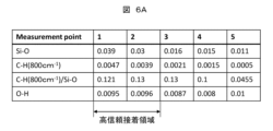
- FIG. 6A is a table showing an example of the measurement results of functional groups at each position of the glass coating layer in FIG. 5.
- 6A shows values of Si—O bond, C—H bond (800 cm ⁇ 1 ), [C—H bond (800 cm ⁇ 1 )/Si—O bond], and O—H bond at positions 1 to 5 shown in FIG. 5.
- the values shown in this figure are peak heights calculated by measuring absorbance by Fourier transform infrared spectroscopy (FTIR) using the ATR method and correcting the background.
- FTIR Fourier transform infrared spectroscopy
- Figure 6B is a graph showing the relationship between Si-O peak height and adhesive strength.
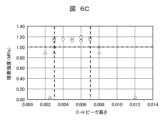
- Figure 6C is a graph showing the relationship between C-H peak height and adhesive strength.
- Figure 6D is a graph showing the relationship between O-H peak height and adhesive strength.
- Figure 6E is a graph showing the relationship between the ratio of the C-H peak to the Si-O peak (relative C-H/Si-O ratio) and adhesive strength.
- the horizontal axis represents the peak height of each functional group, and the vertical axis represents adhesive strength.
- the horizontal axis of the graph in Figure 6E represents the ratio of the C-H peak height to the Si-O peak height (C-H/Si-O relative ratio).
- the adhesive strength of 1.0 MPa which serves as the evaluation standard, is indicated by a dashed line.
- the peak height value of each functional group was obtained by measuring the local absorbance using FTIR (ATR method), plotting the logarithm of absorbance on the vertical axis, and correcting for the background.
- the adhesive strength was measured when a sample with a sealant applied between two steel plates with a glass coating layer was pulled using a tensile tester until the two steel plates separated.
- Figure 6F is a table summarizing the conditions for functional groups that result in highly reliable adhesion from Figures 6B to 6E. In other words, it shows the critical values for the peak height of each functional group.
- the glass coating layer 31a has a highly reliable adhesive region when, in terms of peak height, the SiO bond is 0.03 or more, the CH bond of the CH3 group is 0.003 to 0.007, the OH bond is 0.005 or more, and the C—H/Si—O relative ratio is 0.05 to 0.24.
- the highly reliable adhesive region must satisfy the requirement that the thickness t of the glass coating layer, as measured by film thickness measurement using X-ray fluorescence analysis (XRF), be 50 nm or more and 300 nm or less. If t is less than 50 nm, the corrosion resistance is insufficient, and the airtightness cannot be satisfied after corrosion in a salt damage test or the like. Furthermore, if t exceeds 300 nm, the bonding force within the glass coating layer decreases, the strength of the glass coating layer decreases, interlayer destruction occurs, and sufficient adhesive strength cannot be obtained. For this reason, the highly reliable adhesive region of the glass coating layer must have t of 50 nm or more and 300 nm or less. In other words, it must satisfy the requirement that 50 ⁇ t ⁇ 300 (unit: nm).
- XRF X-ray fluorescence analysis
- the pressure-receiving area of the cover due to the change in internal pressure is 0.03 m 2 , and the maximum internal pressure requirement is 85 kPa. Therefore, the load received by the seal material due to the internal pressure is 2550 N, calculated by multiplying the pressure-receiving area by the internal pressure.
- the adhesive area of the sealant 40 is 0.0027 m2
- the minimum tensile adhesive strength of the silicone adhesive after immersion in water is about 1.0 MPa. Therefore, the adhesive strength at the adhesive area of 0.0027 m2 is 2700 N.
- the load (2550N) that the sealant receives due to changes in internal pressure is smaller than the adhesive strength (2700N) in the sealed area, and taking into account variations in adhesive application, the seal width must be at least 4mm to satisfy the adhesive area required to maintain airtightness when internal pressure changes.
- the highly reliable adhesive region containing a sufficient amount of OH groups and CH3 groups is formed in the glass coating layer 31a to a width of at least 4 mm, and the width of the sealant 40 corresponding to the highly reliable adhesive region of the glass coating layer 31a is set to at least 4 mm as shown in Fig. 2, thereby preventing peeling and cohesive failure of the glass coating layer 31a and satisfying the airtightness, water resistance, and salt damage resistance. That is, the width of the sealant 40 is 4 mm or more, and the width of the glass coating layer 31a is substantially set as the upper limit.
- the glass coating layer 31a is preferably formed as a surface treatment film by a plasma glass coating process that allows high adhesion to the flange portion 31.
- the plasma glass coating process is preferably performed by attaching a nozzle (Plasmatreat: PFW10), a plasma control unit (Plasmatreat: PCU) and a plasma generator (Plasmatreat: FG5002S) to a plasma treatment device (Plasmatreat: PTU1212) and using a material containing an organic substance such as hexamethyldisiloxane or hexamethyldisilazane as a precursor. This allows the glass coating layer 31a having a CH3 group or the like to be formed.
- the precursor is not limited to the above, and may be any precursor having a carbon chain functional group, such as a CH3 group at the end of a Si group.
- the glass coating layer 31a may be formed by a method other than the plasma glass coating process, as long as the method can provide high adhesion to the flange portion 31. It is more preferable that the glass coating layer 31a is formed directly on the flange portion 31 with an adhesive strength of 1.0 MPa or more. This value of 1.0 MPa corresponds to the cohesive failure strength of commonly used silicone-based sealing materials.
- the adhesive strength between the flange portion 31 and the glass coating layer 31a is equal to or greater than the cohesive failure strength of the silicone-based sealant. Therefore, as long as the configuration satisfies this relationship, there are no numerical limitations.
- FIG. 7 is a graph showing an example of the analysis results of the steel sheet surface before bonding in this embodiment.
- the horizontal axis shows the wave number, and the vertical axis shows the logarithm of the absorbance.
- FTIR has detected OH groups at about 3300 cm -1 , CH groups at about 800 cm -1 and 1400 cm -1 , and SiO groups at about 1000 to 1200 cm -1 .
- the values related to the wave numbers measured vary slightly depending on the conditions, and are not limited to the wave numbers shown in this figure. The values are compared with a commonly used FTIR wave number database and include all values that match with OH groups and CH groups.
- the peak height for SiO groups is calculated by connecting the minimum points on both sides of the peak (maximum point) of the curve with straight lines (shown with dashed lines) and setting the zero point of the peak height with a diagonal line, thereby correcting for the background.
- the measurement by FTIR is performed, for example, using a Fourier transform infrared spectrometer (Micro infrared spectrophotometer Nicolet 6700/Continu ⁇ m manufactured by Thermo Fisher Scientific Co., Ltd.) by the ATR method under the conditions of a resolution of 4 cm ⁇ 1 , an MCT detector, and an accumulation count of 64 times, and the peak intensity of each functional group can be handled as a corrected height from the background.
- a Fourier transform infrared spectrometer Micro infrared spectrophotometer Nicolet 6700/Continu ⁇ m manufactured by Thermo Fisher Scientific Co., Ltd.
- the reason for using the ATR method is that, compared with a normal reflection microscopy method, it is possible to measure in a pinpoint range and calculate the functional group without including the inclined portion near the point to be measured, so that the truly necessary high reliability adhesive region can be clarified and the range containing the functional group can be sufficiently determined.
- the measurement device and method are not limited to this, and any device and conditions that can correctly detect surface functional groups can be used.
- the presence of the glass coating layer 31a having the above-mentioned highly reliable adhesive region makes it possible to prevent the flange portion 31 from coming into contact with water, even if the sealing material 40 should absorb water, thereby preventing corrosion of the flange portion 31, etc.
- the number of OH groups that bond with the OH groups of the sealing material through hydrogen bonds is increased compared to the surface state of a normal metal, and the intermolecular force of the CH3 groups and the covalent bond between the SiO groups are provided, so that the adhesive strength can be increased.
- the adhesive strength can be increased regardless of the state of the metal surface, and water resistance can be imparted by the CH3 groups, and durability against salt water, etc. can be imparted.
- the inventors have found that in previous environmental resistance tests for salt water and the like, an adhesive structure like that shown in FIG. 9 described below was able to satisfy the required adhesive strength. However, they have confirmed that the conventional adhesive structure like that shown in FIG. 9 cannot satisfy the increasingly stringent requirements for a long life in environments where the material comes into contact with salt water and the like. They have confirmed that the configuration of this embodiment satisfies the required level.
- a typical sealant for example, a silicone adhesive
- the high reliability adhesive region is arranged so that it receives tensile stress in a direction approximately perpendicular to the adhesive surface when the pressure (internal pressure) in the internal space formed by the first housing 20 and the second housing 30 increases. Therefore, it is possible to achieve high robustness, high adhesion, high reliability, and low cost.
- the width of the sealant can be reduced from 10 mm, which was previously thought to be necessary, to 4 mm, reducing the amount of sealant and glass coating applied, and cycle time. Also, by reducing the width of the sealant from 10 mm, which was previously thought to be necessary, to 4 mm, there is no longer a need to provide a labyrinth shape in the flange, which reduces the processing costs of the housing and the amount of sealant used. In addition, the dimensions of the flange can be reduced, allowing the housing to be made more compact.
- Figure 8 is a schematic cross-sectional view showing the chemical structure of the steel plate surface before bonding in a comparative example.
- This figure shows that OH groups are present on the surface of the housing 131.
- the density of the OH groups is relatively low.
- Figure 9 is a schematic cross-sectional view showing the chemical structure of the steel plate surface after bonding in the comparative example.
- OH groups, CH3 groups, etc. present on the surface of the sealant 140 are shown.
- the housing 131 and the sealant 140 are bonded by forming covalent bonds between SiO groups, and by forming hydrogen bonds between the OH groups present on the surface of the housing 131 and the OH groups of the sealant 140.
- the CH3 groups of the sealant 140 are not bonded to other functional groups because there are no CH3 groups on the surface of the housing 131.
- the adhesive strength is considered to be weaker by the amount of this intermolecular force.
- Figure 10 is a graph showing an example of the analysis results of the steel plate surface before bonding in a comparative example.
- the horizontal axis shows the wave number, and the vertical axis shows the logarithmic value of absorbance.
- FIG. 11 is an exploded perspective view showing the electronic control device according to this embodiment.
- the second housing 30 has an end 33.
- the cross section of the end 33 is L-shaped.
- the first housing 20 is provided with a peripheral groove 20a.
- the second housing 30 is provided with a housing end 30a that is a convex portion.
- FIG. 12 is a cross-sectional view of the main parts of the electronic control device according to this embodiment.
- the first housing 20 is provided with a flange portion 22 (flat portion), and a peripheral groove 20a is provided around the flange portion 22.
- the second housing 30 is provided with a flange portion 31, and an end portion 33 is provided around the flange portion 31. The end portion 33 is fitted into the peripheral groove 20a.
- a glass coating layer 31a is provided on the surface of the flange portion 31 facing the flange portion 22.
- the glass coating layer 31a contains many OH groups and CH3 groups.
- a seal material 40a is sandwiched between the glass coating layer 31a and the flange portion 22. OH groups and CH3 groups are exposed on the surfaces of the seal material 40a and the glass coating layer 31a.
- the gap between the inner wall surface 22a of the peripheral groove 20a and the end 33 is filled with a sealant 40.
- the gap between the inner wall surface 22a and the end 33 forms a labyrinth shape, extending the width of the adhesive surface of the sealant 40.
- the second housing 30 including the flange portion 31 is made of pre-plated steel sheet, there is no plating on the cut surface during molding, so by burying the end 33 in the sealant 40, etc., it is possible to prevent corrosion of the end 33.
- FIG. 13 is a cross-sectional view of the main parts of the electronic control device according to the third embodiment.
- a glass coating layer 22b is also formed on the flange portion 22 side of the first housing 20.
- This configuration allows the sealing material 40 to have a high adhesion structure similar to that of the first embodiment in both the portions that contact the first housing 20 and the second housing 30.
- FIG. 14 is a cross-sectional view of the main parts of the electronic control device according to the fourth embodiment.
- a glass coating layer 22b is also formed on the flange portion 22 side of the first housing 20. Therefore, the sealing material 40a is sandwiched between the glass coating layer 31a and the glass coating layer 22b.
- FIG. 15 is a cross-sectional view of the main parts of the electronic control device according to the fifth embodiment.
- a glass coating layer 22b is also formed on the flange portion 22 side of the first housing 20. Also, in this embodiment, unlike the first embodiment, the seal material 40 is disposed near the peripheral portions of the flange portion 22 and the flange portion 31.
- FIG. 16 is a cross-sectional view of the main parts of the electronic control device according to the sixth embodiment.
- the shapes of the first housing 20 and the second housing 30 are the same as those in FIG. 12.
- the first flat portion 23 on which the printed wiring board 10 is mounted is also the same.
- a glass coating layer 31b is provided on the outer periphery of the flange portion 31.
- a glass coating layer 22c is also provided on the surface of the peripheral groove 20a of the first housing 20 that faces the outer periphery of the flange portion 31.
- a sealant 40a is sandwiched between the glass coating layer 31b and the glass coating layer 22c. The outer surface of the sealant 40a is covered with a sealant 40.
- both the sealing material 40a and the glass coating layers 22c, 31b are arranged so that they receive stress (shear stress) in a direction approximately parallel to the adhesive surface when the pressure (internal pressure) in the internal space formed by the first housing 20 and the second housing 30 increases.
- the present disclosure is not limited to the above-described embodiments, and includes various modified examples.
- the above-described embodiments have been described in detail to clearly explain the present disclosure, and are not necessarily limited to those having all of the configurations described.
- it is possible to replace a part of the configuration of one embodiment with the configuration of another embodiment and it is also possible to add the configuration of another embodiment to the configuration of one embodiment.
- the electronic control device disclosed herein is particularly effective when the housing structure is made of hot-dip galvanized steel plate, which has excellent corrosion resistance, or lightweight aluminum die-casting.
- the configuration of this disclosure can also be used in a configuration that does not use bolts to secure the device, which simplifies the work and reduces costs.
- the configuration of this disclosure can also be used in a configuration in which the electronic control device is clamped and secured by a bracket or the like provided on the vehicle side.
- the configuration of the present disclosure is also applicable to electronic control devices, whose housings are becoming larger and whose connectors have an increasing number of poles as their functionality increases.
- the configuration of the present disclosure is particularly effective in situations where it is difficult to decentralize electronic control devices or to reduce the number of connector terminal poles and make them wireless (one example is an electronic control device for an engine or an electronic control device for a transmission that is mounted in the engine room).
- An electronic control device comprising: a first housing; a second housing fixed opposite to the first housing; and a sealant that seals an internal space formed by the first housing and the second housing, wherein OH groups and CH3 groups are present in the sealant, and at least one of the first housing and the second housing has a glass coating film containing the OH groups and the CH3 groups formed on at least a portion of an area of the surface of the first housing that contacts the sealant.
- the glass coating film has a highly reliable adhesive region with a width of 4 mm or more and a film thickness of 50 nm to 300 nm.
- the high reliability adhesive region is formed directly on the surfaces of the first housing and the second housing with an adhesive strength of 1.0 MPa or more.
- 1, 1A, 1B, 2, 2A, 2B electronic control device
- 10 printed wiring board
- 11 internal space
- 20 first housing, 20a: peripheral groove, 21: opening
- 23 first flat portion
- 50 51: screws
- 60 connector
- 61 housing
- 63 terminal
- 131: housing, 140 sealing material.
Landscapes
- Engineering & Computer Science (AREA)
- Microelectronics & Electronic Packaging (AREA)
- Casings For Electric Apparatus (AREA)
Abstract
L'invention concerne un dispositif de commande électronique (1) comprenant : un premier boîtier (20) et un second boîtier (30) qui logent une carte de circuit imprimé (10) ; une couche de revêtement en verre (31a) formée dans le premier boîtier (20) et/ou le second boîtier (30) ; et un élément d'étanchéité (40) disposé entre le premier boîtier (20) et le second boîtier (30). La couche de revêtement en verre (31a) est disposée de manière à être en contact avec l'élément d'étanchéité (40). Par conséquent, la présente invention peut fournir un dispositif de commande électronique compact ayant une étanchéité à l'air satisfaisant de manière aux exigences strictes pour la prévention de dommages causés par le sel.
Priority Applications (3)
| Application Number | Priority Date | Filing Date | Title |
|---|---|---|---|
| CN202380101611.2A CN121713659A (zh) | 2023-08-22 | 2023-08-22 | 电子控制装置 |
| JP2025541200A JPWO2025041246A1 (fr) | 2023-08-22 | 2023-08-22 | |
| PCT/JP2023/030084 WO2025041246A1 (fr) | 2023-08-22 | 2023-08-22 | Dispositif de commande électronique |
Applications Claiming Priority (1)
| Application Number | Priority Date | Filing Date | Title |
|---|---|---|---|
| PCT/JP2023/030084 WO2025041246A1 (fr) | 2023-08-22 | 2023-08-22 | Dispositif de commande électronique |
Publications (1)
| Publication Number | Publication Date |
|---|---|
| WO2025041246A1 true WO2025041246A1 (fr) | 2025-02-27 |
Family
ID=94731878
Family Applications (1)
| Application Number | Title | Priority Date | Filing Date |
|---|---|---|---|
| PCT/JP2023/030084 Pending WO2025041246A1 (fr) | 2023-08-22 | 2023-08-22 | Dispositif de commande électronique |
Country Status (3)
| Country | Link |
|---|---|
| JP (1) | JPWO2025041246A1 (fr) |
| CN (1) | CN121713659A (fr) |
| WO (1) | WO2025041246A1 (fr) |
Citations (3)
| Publication number | Priority date | Publication date | Assignee | Title |
|---|---|---|---|---|
| JP2014086682A (ja) * | 2012-10-26 | 2014-05-12 | Denso Corp | 収納ケースおよびその製造方法 |
| WO2016017075A1 (fr) * | 2014-08-01 | 2016-02-04 | 信越ポリマー株式会社 | Corps d'entrée en prise imperméable et procédé de fabrication de corps d'entrée en prise imperméable |
| JP2023096624A (ja) * | 2021-12-27 | 2023-07-07 | 株式会社レゾナック | 車載用ecuの製造方法 |
-
2023
- 2023-08-22 JP JP2025541200A patent/JPWO2025041246A1/ja active Pending
- 2023-08-22 WO PCT/JP2023/030084 patent/WO2025041246A1/fr active Pending
- 2023-08-22 CN CN202380101611.2A patent/CN121713659A/zh active Pending
Patent Citations (3)
| Publication number | Priority date | Publication date | Assignee | Title |
|---|---|---|---|---|
| JP2014086682A (ja) * | 2012-10-26 | 2014-05-12 | Denso Corp | 収納ケースおよびその製造方法 |
| WO2016017075A1 (fr) * | 2014-08-01 | 2016-02-04 | 信越ポリマー株式会社 | Corps d'entrée en prise imperméable et procédé de fabrication de corps d'entrée en prise imperméable |
| JP2023096624A (ja) * | 2021-12-27 | 2023-07-07 | 株式会社レゾナック | 車載用ecuの製造方法 |
Also Published As
| Publication number | Publication date |
|---|---|
| CN121713659A (zh) | 2026-03-20 |
| JPWO2025041246A1 (fr) | 2025-02-27 |
Similar Documents
| Publication | Publication Date | Title |
|---|---|---|
| JP6488391B2 (ja) | 車載制御装置 | |
| US11370372B2 (en) | Electronic control device | |
| US10829064B2 (en) | Electronic control device | |
| JP4585828B2 (ja) | 制御装置およびその製造方法 | |
| JP6542642B2 (ja) | 電子制御装置 | |
| US8168896B2 (en) | Electronic housing | |
| US12519023B2 (en) | Module with gas flow-inhibiting sealing at module interface to mounting base | |
| US9756718B2 (en) | Module board | |
| CN101738288B (zh) | 传感器模块和用于制造传感器模块的方法 | |
| JP5188327B2 (ja) | トランスファーモールド型電子制御装置、その製造方法及び変速機 | |
| JP7366276B2 (ja) | 電子制御装置及び製造方法 | |
| US20250240904A1 (en) | Electronic control device | |
| WO2025041246A1 (fr) | Dispositif de commande électronique | |
| JP7836228B2 (ja) | 電子制御装置 | |
| JP5056552B2 (ja) | 電子装置の実装構造 | |
| JP2009049109A (ja) | モジュール装置 |
Legal Events
| Date | Code | Title | Description |
|---|---|---|---|
| 121 | Ep: the epo has been informed by wipo that ep was designated in this application |
Ref document number: 23949707 Country of ref document: EP Kind code of ref document: A1 |
|
| ENP | Entry into the national phase |
Ref document number: 2025541200 Country of ref document: JP Kind code of ref document: A |