WO2025041246A1 - Electronic control device - Google Patents
Electronic control device Download PDFInfo
- Publication number
- WO2025041246A1 WO2025041246A1 PCT/JP2023/030084 JP2023030084W WO2025041246A1 WO 2025041246 A1 WO2025041246 A1 WO 2025041246A1 JP 2023030084 W JP2023030084 W JP 2023030084W WO 2025041246 A1 WO2025041246 A1 WO 2025041246A1
- Authority
- WO
- WIPO (PCT)
- Prior art keywords
- housing
- electronic control
- glass coating
- control device
- coating layer
- Prior art date
- Legal status (The legal status is an assumption and is not a legal conclusion. Google has not performed a legal analysis and makes no representation as to the accuracy of the status listed.)
- Pending
Links
Images


Classifications
-
- H—ELECTRICITY
- H05—ELECTRIC TECHNIQUES NOT OTHERWISE PROVIDED FOR
- H05K—PRINTED CIRCUITS; CASINGS OR CONSTRUCTIONAL DETAILS OF ELECTRIC APPARATUS; MANUFACTURE OF ASSEMBLAGES OF ELECTRICAL COMPONENTS
- H05K5/00—Casings, cabinets or drawers for electric apparatus
- H05K5/06—Hermetically-sealed casings
Definitions
- This disclosure relates to an electronic control device.
- In-vehicle electronic control devices are required to have strict environmental resistance specifications against corrosion and deterioration, as well as a long lifespan.
- a long lifespan is required in environments where salt damage occurs, and a seal structure that prevents the progression of crevice corrosion is important.
- the size of electronic control devices is increasing, but there is a demand for inexpensive, high-quality products.
- pressure differences can occur inside electronic control devices due to altitude changes during air transport, etc., and a seal structure with extremely high pressure resistance of 50 kPa to 85 kPa may be required.
- Patent technology relating to sealing structures includes technology related to Patent Document 1.
- Patent Document 1 describes a storage case having a hollow case member and a lid portion that covers the hollow portion of the case member, in which a bonding thin film made of a silicone-based thin film or a carbon-based thin film is formed on the open end surface of the case member, and the sealing member and the case member are bonded via this bonding thin film, thereby ensuring the sealing structure of the storage case even in harsh environments where seawater (salt water) and the like may adhere to it.
- seawater seawater
- the housings of electronic control devices must be low-profile and lightweight, rather than large in size. This requires molding technology for the housings that maintain a thin wall while suppressing deformation, and because electronic components, not just aluminum electrolytic capacitors, need to be low-profile, the waterproof seal structure must also be low-profile.
- Patent Document 1 describes how to improve the bonding strength by bonding a bonding thin film, such as a silicone-based thin film or a carbon-based thin film, to a sealing member, but there is still room for improvement in obtaining sufficient bonding strength while achieving a low profile and low cost.
- a bonding thin film such as a silicone-based thin film or a carbon-based thin film
- the objective of this disclosure is to provide a compact electronic control device that has highly reliable airtightness and meets the increasingly stringent requirements for preventing salt damage.
- the electronic control device disclosed herein comprises a first housing and a second housing that house a circuit board, a glass coating layer formed on at least one of the first housing and the second housing, and a sealing member provided between the first housing and the second housing, and the glass coating layer is arranged so as to be in contact with the sealing member.
- FIG. 1 is an exploded perspective view showing an electronic control device according to a first embodiment
- 1 is a cross-sectional view of a main portion of an electronic control device according to a first embodiment
- FIG. 2 is a schematic cross-sectional view showing the chemical structure of the surface of a steel sheet before bonding in the first embodiment.
- FIG. 2 is a schematic cross-sectional view showing the chemical structure of the surface of the steel sheet after bonding in the first embodiment.
- FIG. 2 is a schematic cross-sectional view showing a glass coating layer in the first embodiment.
- 6 is a table showing an example of the measurement results of functional groups at each position of the glass coating layer of FIG. 5 .
- 1 is a graph showing the relationship between Si—O peak height and adhesive strength.
- FIG. 1 is a graph showing the relationship between C—H peak height and adhesive strength. 1 is a graph showing the relationship between O-H peak height and adhesive strength. 1 is a graph showing the relationship between the ratio of the C—H peak to the Si—O peak (relative C—H/Si—O ratio) and adhesive strength. 1 is a table showing the critical values of peak heights for each functional group. 4 is a graph showing an example of an analysis result of a steel sheet surface before bonding in the first embodiment.
- FIG. 2 is a schematic cross-sectional view showing the chemical structure of the surface of a steel sheet before bonding in a comparative example.
- FIG. 2 is a schematic cross-sectional view showing the chemical structure of the surface of a steel sheet after bonding in a comparative example.
- FIG. 11 is an exploded perspective view showing an electronic control device according to a second embodiment.
- FIG. 6 is a cross-sectional view of a main part of an electronic control device according to a second embodiment.
- FIG. 11 is a cross-sectional view of a main part of an electronic control device according to a third embodiment.
- FIG. 11 is a cross-sectional view of a main part of an electronic control device according to a fourth embodiment.
- FIG. 13 is a cross-sectional view of a main part of an electronic control device according to a fifth embodiment.
- FIG. 13 is a cross-sectional view of a main part of an electronic control device according to a sixth embodiment.
- FIG. 1 A first embodiment of an electronic control device according to the present disclosure will be described with reference to FIGS. 1 to 7.
- FIG. 1 A first embodiment of an electronic control device according to the present disclosure will be described with reference to FIGS. 1 to 7.
- FIG. 1 A first embodiment of an electronic control device according to the present disclosure will be described with reference to FIGS. 1 to 7.
- FIG. 1 A first embodiment of an electronic control device according to the present disclosure will be described with reference to FIGS. 1 to 7.
- FIG. 1 is an exploded perspective view showing an electronic control device according to the first embodiment. Note that, for convenience of illustration, electronic components mounted on a board are omitted from FIG. 1.
- the electronic control device 1 is composed of a printed wiring board 10 on which electronic components and the like are mounted, a first housing 20 (case), a second housing 30 (cover), a connector 60, sealing material 40, sealing material 41, screws 50, screws 51, etc.
- the printed wiring board 10 is an example of a circuit board, and the contents of this disclosure are not limited to printed wiring boards.
- the sealing materials 40 and 41 are also referred to as "sealing members.”
- the first housing 20, together with the second housing 30, houses the printed wiring board 10 inside and protects the printed wiring board 10 on which electronic components are mounted from water, foreign matter, and the like.
- the first housing 20 is preferably made of metal, and aluminum is preferable, in order to dissipate heat generated by the electronic components and to shield noise. In particular, when the electronic control device 1 is for a direct injection engine, a shielding effect is required.
- the first housing 20 is formed by an aluminum die-casting method using a mold.
- the material of the first housing 20 may be resin.
- the first housing 20 is formed by an injection molding method.
- the second housing 30 is fixed facing the first housing 20, and an internal space 11 (see FIG. 2) is formed between the first housing 20 and the second housing 30.
- a sealant 40 is sandwiched between the flange portion of the first housing 20 and the flange portion 31 of the second housing 30, so that the internal space 11 is sealed.
- the external dimensions of the electronic control unit 1 are preferably approximately 240 mm x 160 mm, which is relatively large for an electronic control unit to be placed in an engine room, with the shape of the top surface being roughly rectangular.
- Conventional electronic control units are usually approximately 160 mm x 160 mm in size, and the electronic control unit 1 of this embodiment is at least 1.5 times the size of such conventional products.
- the first housing 20 is provided with a through opening 21.
- the opening 21 is configured so that the connector 60 can pass through.
- the pressure inside the first housing 20 changes during transportation of the vehicle and in the environment in which it is used, such as changes in altitude and temperature. For this reason, the shape of the center of the first housing 20 changes the most.
- the center of the first housing 20 bulges outward when the internal pressure is high, and dents inward when the internal pressure is low. Therefore, it is preferable that the opening 21 is positioned closer to the periphery when viewed from the center of the first housing 20.
- Heat dissipation fins 25 are provided in the portions of the first housing 20 where no openings 21 are provided.
- the orientation of the heat dissipation fins 25 is parallel to the long sides of the first housing 20.
- the orientation of the heat dissipation fins 25 is not limited to this figure, and may be parallel to the short sides of the first housing 20. It is desirable that the orientation of the heat dissipation fins 25 be parallel to the flow of molten metal from the gate in aluminum die casting.
- the short side of the rectangular first housing 20 and the opposite side to the opening 21 is selected so that it is parallel to the longitudinal direction of the connector 60 and the heat dissipation fins 25, and the overflow position is set on the short side surface opposite the gate or on the side surface.
- the second gate is located on the long side of the rectangular first housing 20, and an overflow is provided on the opposite long side.
- the second gate position can improve the flow of the molten metal and reduce casting defects.
- Improved flow of the molten metal reduces air entrapment, eliminates aluminum die-cast defects such as voids and weld marks, reduces the amount of aluminum that flows to the overflow, and has the advantage of allowing molding at low cost. Poor flow of the molten metal and molding defects such as voids and weld marks can cause a decrease in thermal conductivity and cracks, which may affect the strength and appearance.
- the amount of deformation of the housing after molding becomes large, making it difficult to ensure flatness. In this case, the airtightness of the sealing material decreases, so it is desirable to use a material that can improve the flow of the molten metal.
- the first housing 20 is provided with a number of pedestals for fixing the printed wiring board 10. For example, pedestals are provided that are tapped for tightening the screws 50 and pedestals with a surface precision on which the heat dissipation adhesive 42 is applied. Furthermore, the first housing 20 is also provided with pedestals that are fixed to the second housing 30 via the screws 51.
- the sealant 41 is provided for waterproofing purposes, and in order to protect against foreign matter such as salt water, which is required by the environmental specifications of the engine room, a silicone adhesive that is heat-resistant, water-resistant, chemical-resistant, and flexible is suitable.
- the sealant 40 is provided for waterproofing purposes and is a member that seals the internal space formed by the first housing 20 and the second housing 30.
- a silicone adhesive is suitable for this.
- the long sides of the first housing 20 are most deformed at the center because, when pressure changes within the first housing 20 due to temperature changes, internal pressure is applied to the first housing 20, causing the center of the first housing 20 to bend in the normal direction (upper side in Figure 1). This allows the sealant 40 to have an adhesive strength that can withstand deformation.
- the second housing 30 has holes at its four corners through which screws 51 pass to fasten the first housing 20 and the second housing 30 together.
- the second housing 30 and the first housing 20 are fastened together with the sealing material 40 by the screws 51. It is preferable to place the screws 51 at the four corners so that the application path of the sealing material 40 does not become complicated.
- the electronic control device 1 of this embodiment is approximately 1.5 times larger in size than conventional electronic control devices, so a thin material is selected for the second housing 30, but strength is ensured by providing ribs, dimples, steps, etc.
- Electronic components are mounted on the printed wiring board 10 using a conductive alloy such as solder. They can also be mounted on both sides.
- the electronic components are passive components such as resistors and capacitors, and active components such as semiconductors, and are mounted on the printed wiring board 10 using a surface mounting method or an insertion mounting method. It is preferable to use electronic components with a long life that can withstand the environment in the engine room of an automobile.
- BGAs Bit Grid Arrays
- QFNs Quadrature Arrays
- QFPs Quad Flat Packages
- BGAs have electrodes formed into hemispheres by the surface tension of a conductive alloy attached to terminals arranged in a grid pattern on the bottom of the package, and are joined to the printed wiring board 10 by reflow.
- QFNs have shorter terminals than QFPs, and are connected to the printed wiring board 10 by a conductive alloy. If the printed wiring board 10 deforms significantly, the structure is such that the joints are susceptible to stress, so it is necessary to suppress the amount of deformation of the printed wiring board 10.
- the printed wiring board 10 is fixed to a tapped base of the first housing 20 with a number of screws 50. At this time, the printed wiring board 10 is fixed so that a heat dissipation adhesive 42 is sandwiched between the printed wiring board 10 and the base of the first housing 20, which has a surface precision. With this configuration, heat generated by the electronic components is transferred to the base through the vias of the printed wiring board 10, and dissipated from the surface of the first housing 20, including the heat dissipation fins 25.
- the height position of the printed wiring board 10 is in the middle between the first housing 20 and the second housing 30. Preventing it from leaning to one side limits the height of the mounted electronic components, and avoids the inability to place tall electronic components on both sides. Also, by having the height position of the printed wiring board 10 in the middle between the first housing 20 and the second housing 30, the electronic control device 1 can be made low-profile. Making the electronic control device 1 low-profile makes it easier to secure space when mounting it in an engine compartment, and makes it easier to receive air for cooling.
- the electronic control device 1 of this embodiment is relatively large in size among electronic control devices that are preferably placed in the engine compartment, so four to seven screws 50 are used to secure the printed wiring board 10 to the first housing 20 via the heat dissipation adhesive 42.
- the screws 50 should be positioned with equal distances between each screw 50, taking into consideration the four corners of the printed wiring board 10 and the placement of electronic components. In particular, distortion will occur in the printed wiring board 10 near the screws 50, so it is desirable to position the screws 50 in a way that does not cause distortion in the connector 60 or the joints formed of the conductive alloy of the BGA or QFN, and placing them close to each other should be avoided.
- the screws 50 also function as case earths, and the GND wiring pattern of the printed wiring board 10 is electrically connected to the first housing 20 via the screws 50. It is desirable for the case earths to be located at the four corners of the printed wiring board 10 in terms of routing the wiring pattern of the printed wiring board 10.
- GND stands for ground.
- the printed wiring board 10 is preferably a glass epoxy board made by layering glass fiber cloth and impregnating it with epoxy resin, and is a multi-layer board in which insulators and patterns are stacked. Since high-density mounting is required, it is a multi-layer board with 4 to 8 layers. Also, a through-hole board in which wiring is performed between layers using through-holes or a build-up board using a build-up method are preferable.
- the heat dissipation adhesive 42 transfers heat from the electronic components through the vias in the printed wiring board 10 to the base of the first housing 20, which has a surface precision.
- the thinner the heat dissipation adhesive 42 the easier it is to transfer heat. If the first housing 20 deforms in the normal direction (upper side in Figure 1), the clearance with the printed wiring board 10 increases, and heat dissipation performance decreases. For this reason, it is effective to suppress deformation of the first housing 20.
- Heat-generating electronic components that require heat dissipation are placed under the heat dissipation fins 25.
- the connector 60 is composed of a housing 61, terminals 63, and potting material (not shown in the figure), and is connected to the printed wiring board 10.
- the terminals 63 are press-formed from copper, which has high thermal conductivity.
- the terminals 63 are straight and have a crushed tip, making them easy to insert into the connector on the harness side or into the through-holes of the printed wiring board 10.
- the housing 61 is molded from resin using an injection molding method, and the terminals 63 are pressed into it.
- the housing 61 may also be insert-molded, including the terminals 63.
- a potting material is used to create an airtight seal, as there is a gap between the housing 61 and the terminals 63.
- the size of the connector 60 depends on the number of poles of the terminals 63 and the width of the terminals 63.
- the terminals 63 have both signal terminals and power terminals with different current capacities, with a total of about 60 to 80 poles.
- the power terminals are wider.
- the terminals 63 are connected to the through-holes of the printed wiring board 10 using a conductive alloy (not shown) such as solder. Alternatively, mechanical and electrical connection may be made using press-fit terminals (not shown).
- the first embodiment there are three connectors 60, but this is not limited to three and there may be three or more. Accordingly, there are also three or more openings 21 in the first housing.
- the middle connector 60 By arranging the middle connector 60 on the outermost side, the area for mounting electronic components can be increased. In addition, the wiring pattern of the printed wiring board 10 does not become high density, and overlapping of wiring patterns can be avoided.
- the connector 60 is assembled by connecting it to the outside of the opening 21 of the first housing 20 via the sealant 41, but it may also be connected to the printed wiring board 10 first, and then connected to the inner surface of the opening 21 of the first housing 20 via the sealant 41. Connecting the connector 60 from the outside of the opening 21 of the first housing 20 has the advantage that the seal structure of the connector 60 can be made smaller.
- Sealing material 41 is placed around the bottom edge of the housing 61 of the connector 60 and hardens to seal it.
- the sealing material 41 functions as a buffer, but because the clearance is small, the connector 60 also deforms at the same time.
- the deformation of the connector 60 also affects the terminals 63, and the deformation is simultaneously transmitted to the printed wiring board 10 via the conductive adhesive.
- FIG. 2 is a cross-sectional view of the main parts of the electronic control device according to this embodiment.
- a glass coating layer 31a is provided on the underside of the flange portion 31 of the second housing 30.
- a sealant 40 is sandwiched between this glass coating layer 31a and the flange portion 22 of the first housing 20.
- the width of the sealant 40 is 4 mm.
- the width of the sealant 40 refers to the dimension between the end of the sealant 40 on the outer periphery side of the flange portion 31 and the end of the sealant 40 on the inner periphery side. In other words, the width is equal to the distance from the left end to the right end of the sealant 40 in the figure.
- the second housing 30 is a pre-plated steel plate, since there is no plating on the cut surface during molding, it is desirable to protect the end 33 with a glass coating layer 33a or the like. This is to prevent corrosion of the steel plate.
- the glass coating layer 31a even if the sealing material 40 happens to absorb water, the glass coating layer 31a can prevent the flange portion 31 from coming into direct contact with water, and corrosion of the flange portion 31 can be prevented.
- the material for the second housing 30, which serves as the cover is preferably an iron or aluminum plate material, but resin or aluminum die-casting may also be used. Metal is more suitable from the standpoint of EMC.
- the second housing 30 is preferably made of a steel plate of a uniform thickness and formed by a press forming method.
- a steel plate it is even more preferable if it is plated.
- materials with high corrosion resistance in the engine room environment such as zinc, aluminum, or magnesium, are preferable.
- the surface of the glass coating layer 31a is formed parallel to the first housing 20 or the second housing 30.
- FIG. 3 is a schematic cross-sectional view showing the chemical structure of the steel sheet surface before bonding in this embodiment.
- a glass coating layer 31a is formed on the surface of a flange portion 31 made of a steel plate.
- OH groups and CH3 groups are present on the surface of the glass coating layer 31a.
- FIG. 4 is a schematic cross-sectional view showing the chemical structure of the steel plate surface after bonding in this embodiment.
- the SiO groups of the glass coating layer 31a react with the SiO groups of the sealant 40 to form covalent bonds.
- the OH groups on the surface of the glass coating layer 31a and the OH groups on the surface of the sealant 40 form hydrogen bonds.
- the CH3 groups on the surface of the glass coating layer 31a and the CH3 groups on the surface of the sealant 40 are bonded together by intermolecular forces (van der Waals forces).
- the solid line representing the single bond connecting the glass coating layer 31a and the sealant 40 and O represent covalent bonds.
- the dashed line connecting the O and H of the OH group represent hydrogen bonds.
- the glass coating layer 31a has a greater number of SiO and OH groups than the surface of a conventional exposed housing, making the hydrogen bonds and covalent bonds stronger than before.
- the interface after bonding is made hydrophobic compared to conventional structures, improving waterproofing and allowing the high adhesive strength to be maintained even after salt damage testing.
- FIG. 5 is a schematic cross-sectional view showing the glass coating layer in this embodiment.
- a glass coating layer 31a having a predetermined dimension is formed on the surface of the flange portion 31.
- the cross section of the glass coating layer 31a shown in this figure in the width direction is a mountain shape with a flat top portion.
- the thickness of the glass coating layer 31a is represented by t.
- the central portion of the glass coating layer 31a is indicated by the reference number 1, and the positions at equal intervals of 2 mm are indicated by the reference numbers 2 to 5.
- the positions indicated by the reference numbers 1 and 2 belong to the flat top portion of the glass coating layer 31a.
- the positions indicated by the reference numbers 3 to 5 belong to the slope of the glass coating layer 31a.
- the range between the reference number 2 on the left side of the diagram and the reference number 2 on the right side of the diagram is close to the center of the glass coating process, so the layer thickness t is stable and the functional group content is also stable. This range indicates the high reliability adhesion region described below.
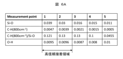
- FIG. 6A is a table showing an example of the measurement results of functional groups at each position of the glass coating layer in FIG. 5.
- 6A shows values of Si—O bond, C—H bond (800 cm ⁇ 1 ), [C—H bond (800 cm ⁇ 1 )/Si—O bond], and O—H bond at positions 1 to 5 shown in FIG. 5.
- the values shown in this figure are peak heights calculated by measuring absorbance by Fourier transform infrared spectroscopy (FTIR) using the ATR method and correcting the background.
- FTIR Fourier transform infrared spectroscopy
- Figure 6B is a graph showing the relationship between Si-O peak height and adhesive strength.
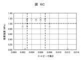
- Figure 6C is a graph showing the relationship between C-H peak height and adhesive strength.
- Figure 6D is a graph showing the relationship between O-H peak height and adhesive strength.
- Figure 6E is a graph showing the relationship between the ratio of the C-H peak to the Si-O peak (relative C-H/Si-O ratio) and adhesive strength.
- the horizontal axis represents the peak height of each functional group, and the vertical axis represents adhesive strength.
- the horizontal axis of the graph in Figure 6E represents the ratio of the C-H peak height to the Si-O peak height (C-H/Si-O relative ratio).
- the adhesive strength of 1.0 MPa which serves as the evaluation standard, is indicated by a dashed line.
- the peak height value of each functional group was obtained by measuring the local absorbance using FTIR (ATR method), plotting the logarithm of absorbance on the vertical axis, and correcting for the background.
- the adhesive strength was measured when a sample with a sealant applied between two steel plates with a glass coating layer was pulled using a tensile tester until the two steel plates separated.
- Figure 6F is a table summarizing the conditions for functional groups that result in highly reliable adhesion from Figures 6B to 6E. In other words, it shows the critical values for the peak height of each functional group.
- the glass coating layer 31a has a highly reliable adhesive region when, in terms of peak height, the SiO bond is 0.03 or more, the CH bond of the CH3 group is 0.003 to 0.007, the OH bond is 0.005 or more, and the C—H/Si—O relative ratio is 0.05 to 0.24.
- the highly reliable adhesive region must satisfy the requirement that the thickness t of the glass coating layer, as measured by film thickness measurement using X-ray fluorescence analysis (XRF), be 50 nm or more and 300 nm or less. If t is less than 50 nm, the corrosion resistance is insufficient, and the airtightness cannot be satisfied after corrosion in a salt damage test or the like. Furthermore, if t exceeds 300 nm, the bonding force within the glass coating layer decreases, the strength of the glass coating layer decreases, interlayer destruction occurs, and sufficient adhesive strength cannot be obtained. For this reason, the highly reliable adhesive region of the glass coating layer must have t of 50 nm or more and 300 nm or less. In other words, it must satisfy the requirement that 50 ⁇ t ⁇ 300 (unit: nm).
- XRF X-ray fluorescence analysis
- the pressure-receiving area of the cover due to the change in internal pressure is 0.03 m 2 , and the maximum internal pressure requirement is 85 kPa. Therefore, the load received by the seal material due to the internal pressure is 2550 N, calculated by multiplying the pressure-receiving area by the internal pressure.
- the adhesive area of the sealant 40 is 0.0027 m2
- the minimum tensile adhesive strength of the silicone adhesive after immersion in water is about 1.0 MPa. Therefore, the adhesive strength at the adhesive area of 0.0027 m2 is 2700 N.
- the load (2550N) that the sealant receives due to changes in internal pressure is smaller than the adhesive strength (2700N) in the sealed area, and taking into account variations in adhesive application, the seal width must be at least 4mm to satisfy the adhesive area required to maintain airtightness when internal pressure changes.
- the highly reliable adhesive region containing a sufficient amount of OH groups and CH3 groups is formed in the glass coating layer 31a to a width of at least 4 mm, and the width of the sealant 40 corresponding to the highly reliable adhesive region of the glass coating layer 31a is set to at least 4 mm as shown in Fig. 2, thereby preventing peeling and cohesive failure of the glass coating layer 31a and satisfying the airtightness, water resistance, and salt damage resistance. That is, the width of the sealant 40 is 4 mm or more, and the width of the glass coating layer 31a is substantially set as the upper limit.
- the glass coating layer 31a is preferably formed as a surface treatment film by a plasma glass coating process that allows high adhesion to the flange portion 31.
- the plasma glass coating process is preferably performed by attaching a nozzle (Plasmatreat: PFW10), a plasma control unit (Plasmatreat: PCU) and a plasma generator (Plasmatreat: FG5002S) to a plasma treatment device (Plasmatreat: PTU1212) and using a material containing an organic substance such as hexamethyldisiloxane or hexamethyldisilazane as a precursor. This allows the glass coating layer 31a having a CH3 group or the like to be formed.
- the precursor is not limited to the above, and may be any precursor having a carbon chain functional group, such as a CH3 group at the end of a Si group.
- the glass coating layer 31a may be formed by a method other than the plasma glass coating process, as long as the method can provide high adhesion to the flange portion 31. It is more preferable that the glass coating layer 31a is formed directly on the flange portion 31 with an adhesive strength of 1.0 MPa or more. This value of 1.0 MPa corresponds to the cohesive failure strength of commonly used silicone-based sealing materials.
- the adhesive strength between the flange portion 31 and the glass coating layer 31a is equal to or greater than the cohesive failure strength of the silicone-based sealant. Therefore, as long as the configuration satisfies this relationship, there are no numerical limitations.
- FIG. 7 is a graph showing an example of the analysis results of the steel sheet surface before bonding in this embodiment.
- the horizontal axis shows the wave number, and the vertical axis shows the logarithm of the absorbance.
- FTIR has detected OH groups at about 3300 cm -1 , CH groups at about 800 cm -1 and 1400 cm -1 , and SiO groups at about 1000 to 1200 cm -1 .
- the values related to the wave numbers measured vary slightly depending on the conditions, and are not limited to the wave numbers shown in this figure. The values are compared with a commonly used FTIR wave number database and include all values that match with OH groups and CH groups.
- the peak height for SiO groups is calculated by connecting the minimum points on both sides of the peak (maximum point) of the curve with straight lines (shown with dashed lines) and setting the zero point of the peak height with a diagonal line, thereby correcting for the background.
- the measurement by FTIR is performed, for example, using a Fourier transform infrared spectrometer (Micro infrared spectrophotometer Nicolet 6700/Continu ⁇ m manufactured by Thermo Fisher Scientific Co., Ltd.) by the ATR method under the conditions of a resolution of 4 cm ⁇ 1 , an MCT detector, and an accumulation count of 64 times, and the peak intensity of each functional group can be handled as a corrected height from the background.
- a Fourier transform infrared spectrometer Micro infrared spectrophotometer Nicolet 6700/Continu ⁇ m manufactured by Thermo Fisher Scientific Co., Ltd.
- the reason for using the ATR method is that, compared with a normal reflection microscopy method, it is possible to measure in a pinpoint range and calculate the functional group without including the inclined portion near the point to be measured, so that the truly necessary high reliability adhesive region can be clarified and the range containing the functional group can be sufficiently determined.
- the measurement device and method are not limited to this, and any device and conditions that can correctly detect surface functional groups can be used.
- the presence of the glass coating layer 31a having the above-mentioned highly reliable adhesive region makes it possible to prevent the flange portion 31 from coming into contact with water, even if the sealing material 40 should absorb water, thereby preventing corrosion of the flange portion 31, etc.
- the number of OH groups that bond with the OH groups of the sealing material through hydrogen bonds is increased compared to the surface state of a normal metal, and the intermolecular force of the CH3 groups and the covalent bond between the SiO groups are provided, so that the adhesive strength can be increased.
- the adhesive strength can be increased regardless of the state of the metal surface, and water resistance can be imparted by the CH3 groups, and durability against salt water, etc. can be imparted.
- the inventors have found that in previous environmental resistance tests for salt water and the like, an adhesive structure like that shown in FIG. 9 described below was able to satisfy the required adhesive strength. However, they have confirmed that the conventional adhesive structure like that shown in FIG. 9 cannot satisfy the increasingly stringent requirements for a long life in environments where the material comes into contact with salt water and the like. They have confirmed that the configuration of this embodiment satisfies the required level.
- a typical sealant for example, a silicone adhesive
- the high reliability adhesive region is arranged so that it receives tensile stress in a direction approximately perpendicular to the adhesive surface when the pressure (internal pressure) in the internal space formed by the first housing 20 and the second housing 30 increases. Therefore, it is possible to achieve high robustness, high adhesion, high reliability, and low cost.
- the width of the sealant can be reduced from 10 mm, which was previously thought to be necessary, to 4 mm, reducing the amount of sealant and glass coating applied, and cycle time. Also, by reducing the width of the sealant from 10 mm, which was previously thought to be necessary, to 4 mm, there is no longer a need to provide a labyrinth shape in the flange, which reduces the processing costs of the housing and the amount of sealant used. In addition, the dimensions of the flange can be reduced, allowing the housing to be made more compact.
- Figure 8 is a schematic cross-sectional view showing the chemical structure of the steel plate surface before bonding in a comparative example.
- This figure shows that OH groups are present on the surface of the housing 131.
- the density of the OH groups is relatively low.
- Figure 9 is a schematic cross-sectional view showing the chemical structure of the steel plate surface after bonding in the comparative example.
- OH groups, CH3 groups, etc. present on the surface of the sealant 140 are shown.
- the housing 131 and the sealant 140 are bonded by forming covalent bonds between SiO groups, and by forming hydrogen bonds between the OH groups present on the surface of the housing 131 and the OH groups of the sealant 140.
- the CH3 groups of the sealant 140 are not bonded to other functional groups because there are no CH3 groups on the surface of the housing 131.
- the adhesive strength is considered to be weaker by the amount of this intermolecular force.
- Figure 10 is a graph showing an example of the analysis results of the steel plate surface before bonding in a comparative example.
- the horizontal axis shows the wave number, and the vertical axis shows the logarithmic value of absorbance.
- FIG. 11 is an exploded perspective view showing the electronic control device according to this embodiment.
- the second housing 30 has an end 33.
- the cross section of the end 33 is L-shaped.
- the first housing 20 is provided with a peripheral groove 20a.
- the second housing 30 is provided with a housing end 30a that is a convex portion.
- FIG. 12 is a cross-sectional view of the main parts of the electronic control device according to this embodiment.
- the first housing 20 is provided with a flange portion 22 (flat portion), and a peripheral groove 20a is provided around the flange portion 22.
- the second housing 30 is provided with a flange portion 31, and an end portion 33 is provided around the flange portion 31. The end portion 33 is fitted into the peripheral groove 20a.
- a glass coating layer 31a is provided on the surface of the flange portion 31 facing the flange portion 22.
- the glass coating layer 31a contains many OH groups and CH3 groups.
- a seal material 40a is sandwiched between the glass coating layer 31a and the flange portion 22. OH groups and CH3 groups are exposed on the surfaces of the seal material 40a and the glass coating layer 31a.
- the gap between the inner wall surface 22a of the peripheral groove 20a and the end 33 is filled with a sealant 40.
- the gap between the inner wall surface 22a and the end 33 forms a labyrinth shape, extending the width of the adhesive surface of the sealant 40.
- the second housing 30 including the flange portion 31 is made of pre-plated steel sheet, there is no plating on the cut surface during molding, so by burying the end 33 in the sealant 40, etc., it is possible to prevent corrosion of the end 33.
- FIG. 13 is a cross-sectional view of the main parts of the electronic control device according to the third embodiment.
- a glass coating layer 22b is also formed on the flange portion 22 side of the first housing 20.
- This configuration allows the sealing material 40 to have a high adhesion structure similar to that of the first embodiment in both the portions that contact the first housing 20 and the second housing 30.
- FIG. 14 is a cross-sectional view of the main parts of the electronic control device according to the fourth embodiment.
- a glass coating layer 22b is also formed on the flange portion 22 side of the first housing 20. Therefore, the sealing material 40a is sandwiched between the glass coating layer 31a and the glass coating layer 22b.
- FIG. 15 is a cross-sectional view of the main parts of the electronic control device according to the fifth embodiment.
- a glass coating layer 22b is also formed on the flange portion 22 side of the first housing 20. Also, in this embodiment, unlike the first embodiment, the seal material 40 is disposed near the peripheral portions of the flange portion 22 and the flange portion 31.
- FIG. 16 is a cross-sectional view of the main parts of the electronic control device according to the sixth embodiment.
- the shapes of the first housing 20 and the second housing 30 are the same as those in FIG. 12.
- the first flat portion 23 on which the printed wiring board 10 is mounted is also the same.
- a glass coating layer 31b is provided on the outer periphery of the flange portion 31.
- a glass coating layer 22c is also provided on the surface of the peripheral groove 20a of the first housing 20 that faces the outer periphery of the flange portion 31.
- a sealant 40a is sandwiched between the glass coating layer 31b and the glass coating layer 22c. The outer surface of the sealant 40a is covered with a sealant 40.
- both the sealing material 40a and the glass coating layers 22c, 31b are arranged so that they receive stress (shear stress) in a direction approximately parallel to the adhesive surface when the pressure (internal pressure) in the internal space formed by the first housing 20 and the second housing 30 increases.
- the present disclosure is not limited to the above-described embodiments, and includes various modified examples.
- the above-described embodiments have been described in detail to clearly explain the present disclosure, and are not necessarily limited to those having all of the configurations described.
- it is possible to replace a part of the configuration of one embodiment with the configuration of another embodiment and it is also possible to add the configuration of another embodiment to the configuration of one embodiment.
- the electronic control device disclosed herein is particularly effective when the housing structure is made of hot-dip galvanized steel plate, which has excellent corrosion resistance, or lightweight aluminum die-casting.
- the configuration of this disclosure can also be used in a configuration that does not use bolts to secure the device, which simplifies the work and reduces costs.
- the configuration of this disclosure can also be used in a configuration in which the electronic control device is clamped and secured by a bracket or the like provided on the vehicle side.
- the configuration of the present disclosure is also applicable to electronic control devices, whose housings are becoming larger and whose connectors have an increasing number of poles as their functionality increases.
- the configuration of the present disclosure is particularly effective in situations where it is difficult to decentralize electronic control devices or to reduce the number of connector terminal poles and make them wireless (one example is an electronic control device for an engine or an electronic control device for a transmission that is mounted in the engine room).
- An electronic control device comprising: a first housing; a second housing fixed opposite to the first housing; and a sealant that seals an internal space formed by the first housing and the second housing, wherein OH groups and CH3 groups are present in the sealant, and at least one of the first housing and the second housing has a glass coating film containing the OH groups and the CH3 groups formed on at least a portion of an area of the surface of the first housing that contacts the sealant.
- the glass coating film has a highly reliable adhesive region with a width of 4 mm or more and a film thickness of 50 nm to 300 nm.
- the high reliability adhesive region is formed directly on the surfaces of the first housing and the second housing with an adhesive strength of 1.0 MPa or more.
- 1, 1A, 1B, 2, 2A, 2B electronic control device
- 10 printed wiring board
- 11 internal space
- 20 first housing, 20a: peripheral groove, 21: opening
- 23 first flat portion
- 50 51: screws
- 60 connector
- 61 housing
- 63 terminal
- 131: housing, 140 sealing material.
Landscapes
- Engineering & Computer Science (AREA)
- Microelectronics & Electronic Packaging (AREA)
- Casings For Electric Apparatus (AREA)
Abstract
Description
本開示は、電子制御装置に関する。 This disclosure relates to an electronic control device.
車載用の電子制御装置は、腐食や劣化に関する厳しい耐環境仕様と長寿命が求められている。特に、塩害が生じる環境下での長寿命化が求められており、隙間腐食の進展を回避するシール構造が重要である。また、車両の高機能化及び機能統合に伴い、電子制御装置のサイズが大型化している一方、安価でかつ高品質な製品が求められている。また、航空輸送などの際における高度変化に伴い、電子制御装置内に圧力差が生じる場合もあり、50kPa~85kPaという非常に高い耐圧を有するシール構造が求められる場合がある。 In-vehicle electronic control devices are required to have strict environmental resistance specifications against corrosion and deterioration, as well as a long lifespan. In particular, a long lifespan is required in environments where salt damage occurs, and a seal structure that prevents the progression of crevice corrosion is important. Furthermore, as vehicles become more sophisticated and functionally integrated, the size of electronic control devices is increasing, but there is a demand for inexpensive, high-quality products. Furthermore, pressure differences can occur inside electronic control devices due to altitude changes during air transport, etc., and a seal structure with extremely high pressure resistance of 50 kPa to 85 kPa may be required.
シール構造に関する特許技術として、特許文献1に関する技術がある。特許文献1には、中空のケース部材と、ケース部材の中空部を覆う蓋部と、を有する収納ケースにおいて、ケース部材の開口端面に、シリコーン系薄膜もしくはカーボン系薄膜の接合用薄膜を形成しておき、この接合用薄膜を介してシール部材とケース部材とが接着されるようにした構成により、海水(塩水)等が付着するような過酷な環境下においても、収納ケースの密封構造を確保したものが記載されている。
Patent technology relating to sealing structures includes technology related to
電子制御装置の高機能化、統合化、大型化等により、シールする部位が増える傾向があるが、コストを抑制するためには、シール材の使用量を減らすことが必要である。 As electronic control devices become more sophisticated, integrated, and larger, the number of parts that need to be sealed tends to increase, but in order to keep costs down, it is necessary to reduce the amount of sealing material used.
一方で、昨今の異常気象等で、自動車が水没する事態が発生しやすくなっているため、シールに対する要求レベルが高くなっている。 On the other hand, recent abnormal weather conditions have made it more likely that cars will become submerged in water, so the requirements for seals are rising.
また、電子制御装置の筐体は、自動車で求められる燃費改善に寄与するため、サイズの大型化に相反して、低背化と軽量化が求められる。そのため、変形を抑えつつ薄肉化を維持した筐体の成形技術が必要であるとともに、アルミニウム電解コンデンサだけでなく電子部品の低背化が必要であることから、防水するシール構造も低背化する必要がある。 In addition, to contribute to the fuel efficiency improvements required for automobiles, the housings of electronic control devices must be low-profile and lightweight, rather than large in size. This requires molding technology for the housings that maintain a thin wall while suppressing deformation, and because electronic components, not just aluminum electrolytic capacitors, need to be low-profile, the waterproof seal structure must also be low-profile.
以上のような状況の中で、低コストでかつ高い接着力を発揮する接着技術が求められている。 In light of the above circumstances, there is a demand for adhesive technology that is low cost and provides high adhesive strength.
本発明者は、塩水等が接触する環境における長寿命化について鋭意検討した結果、金属表面にシール材を塗布するのみでの気密構造では、金属表面に存在するOH基とシール材のOH基との間での水素結合による接着に頼る形であるが、金属表面に存在するOH基が安定しない場合、十分な塩害の防止を達成できず、リーク不良が発生してしまう場合がある点で改善の余地があることを見出した。 The inventors conducted extensive research into extending the life of sealants in environments where they come into contact with salt water, etc., and discovered that there is room for improvement in that an airtight structure created by simply applying a sealant to a metal surface relies on adhesion through hydrogen bonding between the OH groups on the metal surface and the OH groups of the sealant, but if the OH groups on the metal surface are not stable, sufficient salt damage cannot be prevented, and leak defects may occur.
特許文献1においては、シリコーン系薄膜もしくはカーボン系薄膜の接合用薄膜とシール部材とを接着することで接合強度を向上させることの記載があるが、低背化・低コスト化を実現しつつ十分な接着強度を得ることに対しては検討の余地が残されている。
本開示の目的は、厳格化している塩害防止の要請を満たす信頼性が高い気密性を有し、かつ、コンパクトな電子制御装置を提供することにある。 The objective of this disclosure is to provide a compact electronic control device that has highly reliable airtightness and meets the increasingly stringent requirements for preventing salt damage.
本開示の電子制御装置は、回路基板を収容する第1筐体及び第2筐体と、第1筐体及び第2筐体の少なくともいずれか一方に形成されたガラスコート層と、第1筐体と第2筐体との間に設けられたシール部材と、を備え、ガラスコート層は、シール部材と接するように配置されている。 The electronic control device disclosed herein comprises a first housing and a second housing that house a circuit board, a glass coating layer formed on at least one of the first housing and the second housing, and a sealing member provided between the first housing and the second housing, and the glass coating layer is arranged so as to be in contact with the sealing member.
本開示によれば、厳格化している塩害防止の要請を満たす信頼性が高い気密性を有し、かつ、コンパクトな電子制御装置を提供することができる。上記した以外の課題、構成および効果は、以下の実施例の説明により明らかにされる。 This disclosure makes it possible to provide a compact electronic control device that has a highly reliable airtightness that meets the increasingly stringent requirements for preventing salt damage. Issues, configurations, and effects other than those described above will become clear from the description of the examples below.
以下に本開示の第1乃至第6実施形態による電子制御装置を、図面を用いて説明する。なお、本明細書で用いる図面において、同一のまたは対応する構成要素には同一、または類似の符号を付け、これらの構成要素については繰り返しの説明を省略する場合がある。 The electronic control device according to the first to sixth embodiments of the present disclosure will be described below with reference to the drawings. Note that in the drawings used in this specification, identical or corresponding components are given the same or similar reference numerals, and repeated description of these components may be omitted.
<第1実施形態>
本開示の電子制御装置の第1実施形態について図1乃至図7を用いて説明する。
First Embodiment
A first embodiment of an electronic control device according to the present disclosure will be described with reference to FIGS. 1 to 7. FIG.
最初に、電子制御装置の全体構成について図1を用いて説明する。 First, the overall configuration of the electronic control device will be explained using Figure 1.
図1は、第1実施形態に係る電子制御装置を示す分解斜視図である。なお、図1では、図示の都合上、基板に実装している電子部品等は省略している。 FIG. 1 is an exploded perspective view showing an electronic control device according to the first embodiment. Note that, for convenience of illustration, electronic components mounted on a board are omitted from FIG. 1.
図1に示すように、電子制御装置1は、電子部品等が実装されているプリント配線基板10、第1筐体20(ケース)、第2筐体30(カバー)、コネクタ60、シール材40、シール材41、ねじ50、ねじ51等から構成されている。なお、プリント配線基板10は、回路基板の一例であり、本開示の内容は、プリント配線基板に限定されるものではない。ここで、シール材40、41は、「シール部材」ともいう。
As shown in FIG. 1, the
第1筐体20は、第2筐体30と合わせて、内部にプリント配線基板10を収容し、電子部品を実装したプリント配線基板10を水や異物などから保護する。第1筐体20は、電子部品で発生する熱を放熱するためやノイズをシールドするために、金属が好ましく、アルミニウムが好適である。特に、電子制御装置1が直噴エンジン用の場合は、シールド効果が求められる。
The
第1筐体20は、金型を用いたアルミダイカスト成形法により成形する。放熱やシールドが不要な電子部品で構成された電子制御装置の場合は、第1筐体20の材料は樹脂でもよい。樹脂の場合は、射出成形法により第1筐体20を成形する。
The
第2筐体30は、第1筐体20に対向して固定され、第1筐体20と第2筐体30との間には、内部空間11(図2参照)が形成される。第1筐体20のフランジ部と第2筐体30のフランジ部31との間には、シール材40が挟み込まれるため、内部空間11は密封される。
The
電子制御装置1の外形は、好適には240mm×160mmぐらいであり、エンジンルーム内に配置される電子制御装置の中では比較的サイズが大きく、上面の形状が略長方形である。従来の電子制御装置は、通常、160mm×160mm程度のサイズであり、本実施形態の電子制御装置1は、そのような従来品に比べて1.5倍以上のサイズである。
The external dimensions of the
第1筐体20には、貫通した開口部21が設けられている。開口部21は、コネクタ60が貫通するように構成されている。第1筐体20は、高度変化、温度変化など、自動車の輸送や使用する環境下において、第1筐体20の内部の圧力が変化する。このため、第1筐体20の中央部の形状が最も大きく変化する。第1筐体20の中央部は、内部の圧力が高い場合は外側に向かって膨らみ、内部の圧力が低い場合は内側に向かって凹む。したがって、開口部21は、第1筐体20の中央部から見て周縁部寄りに配置されることが好ましい。
The
第1筐体20において開口部21を設けていない部分には、放熱フィン25を設けている。放熱フィン25の向きは、図1においては、第1筐体20の長辺に平行としている。なお、放熱フィン25の向きは、本図に限定されるものではなく、第1筐体20の短辺に平行としてもよい。放熱フィン25の向きは、アルミダイカスト成形におけるゲートからの湯流れに平行とすることが望ましい。
アルミダイカスト成形におけるゲートの位置は、二種類ある。 There are two types of gate positions in aluminum die casting.
まず、一つ目は、コネクタ60の長手方向ならびに放熱フィン25に平行するように、長方形の第1筐体20の短辺側、且つ、開口部21と反対側を選定し、オーバーフローの位置は、ゲートと反対側の短辺側の面や側面側の面に設ける。
First, the short side of the rectangular
また、二つ目のゲートの位置は、長方形の第1筐体20の長辺側に設け、反対側の長辺側に、オーバーフローを設ける。サイズが大きく長方形の場合、アルミニウムが凝固する時間内に成形する必要があり、2つ目のゲート位置の方が、湯流れを改善でき、鋳造不良を少なくすることができる。湯流れが改善されると、空気の巻き込みが少なくなり、巣やウェルドマークなどのアルミダイカストの欠陥がなくなり、オーバーフローへ流れるアルミニウムの量が減り、低コストで成形することができる利点がある。湯流れが悪く、巣やウェルドマーク等の成形不良があると、熱伝導度の低下やクラックの原因となり、強度や外観に影響を与えるおそれがある。さらに、成形後の筐体の変形量が大きくなり、平面度を確保することが難しくなる。この場合、シール材による気密性が低下してしまうため、湯流れを改善できるものとすることが望ましい。
The second gate is located on the long side of the rectangular
第1筐体20には、プリント配線基板10を固定するための複数の台座が設けられている。例えば、ねじ50を締めるためのタップ加工を施している台座や放熱接着剤42が塗布される面精度を有する台座が設けてある。更に、第1筐体20には、ねじ51を介して第2筐体30に固定される台座も設けている。
The
シール材41は、防水のために設けられており、エンジンルームの環境仕様で要求される塩水等の異物を保護するため、耐熱性、耐水性、耐薬品性及び柔軟性のあるシリコーン接着剤が好適である。
The
シール材40は、防水するために設けられており、第1筐体20と第2筐体30によって形成される内部空間を封止する部材であり、シール材41と同様に、シリコーン接着剤が好適である。特に、第1筐体20の長辺は、温度変化による第1筐体20内の圧力変化において、第1筐体20に内圧がかかり、第1筐体20の中心が法線方向(図1の上側)に湾曲する変形になるため、長辺の中心が最も変形する。そのため、シール材40は、変形に耐え得る接着力を持つことができる。
The
第2筐体30には、第1筐体20と第2筐体30とを固定するねじ51を貫通させる穴が四隅に設けられている。第2筐体30と第1筐体20とは、シール材40とともに、ねじ51により固定される。シール材40の塗布軌跡が複雑とならないように、四隅にねじ51を配置することが望ましい。本実施形態の電子制御装置1は、従来の電子制御装置に比べて、サイズが約1.5倍大きいため、第2筐体30には薄肉の材料を選定しているが、リブやディンプル、段差などを設けて強度を確保している。
The
プリント配線基板10は、はんだ等の導電性合金を用いて電子部品等を実装する。両面に実装することもできる。電子部品は、抵抗やコンデンサ等の受動部品と、半導体等の能動部品であり、プリント配線基板10に表面実装方式や挿入実装方式により実装する。自動車用のエンジンルーム環境下に耐えうる高寿命な電子部品を採用することが望ましい。
Electronic components are mounted on the printed
電子部品のパッケージとして実装密度を上げるために、リード端子が延伸されたQFP(Quad Flat Package)とともに、高密度なBGA(Ball Grid Array)やQFN(Quad For Non-Lead Package)を用いている。BGAは、パッケージ底面の格子状に並ぶ端子へ、導電性合金の表面張力で半球状に形成された電極を持ち、プリント配線基板10とリフローで接合される。QFNは、QFPより端子が短く、導電性合金によりプリント配線基板10に接続される。プリント配線基板10の変形量が大きいと、接合部に応力を受けやすい構造であり、プリント配線基板10の変形量を抑制する必要がある。
In order to increase the packaging density of electronic components, high-density BGAs (Ball Grid Arrays) and QFNs (Quad For Non-Lead Packages) are used along with QFPs (Quad Flat Packages) with extended lead terminals. BGAs have electrodes formed into hemispheres by the surface tension of a conductive alloy attached to terminals arranged in a grid pattern on the bottom of the package, and are joined to the printed
プリント配線基板10は、複数のねじ50とともに、第1筐体20のタップ加工した台座に固定する。その際に、プリント配線基板10と第1筐体20の面精度を有する台座との間に放熱接着剤42を挟むように固定する。このような構成により、電子部品で発生する熱をプリント配線基板10のビアを介して台座に伝え、放熱フィン25を含めた第1筐体20の表面より放熱する。
The printed
プリント配線基板10の高さ位置は、第1筐体20と第2筐体30との中央にあることが望ましい。どちらか片方に寄ることを防ぐことで、搭載する電子部品の高さに制限を与え、両面に背の高い電子部品を配置できなくなることを避けることができる。また、プリント配線基板10の高さ位置が第1筐体20と第2筐体30の中央にあることで、電子制御装置1を低背にすることができる。電子制御装置1を低背にすることで、エンジンルーム内に搭載するとして、スペースを確保しやすくなり、冷却するための風を受け易くすることができる。
It is desirable that the height position of the printed
上述のように、本実施形態の電子制御装置1は、好適にはエンジンルーム内に配置される電子制御装置の中では比較的にサイズが大きいため、放熱接着剤42を介してプリント配線基板10を第1筐体20に固定するねじ50は、四本から七本用いる。
As described above, the
ねじ50の位置は、プリント配線基板10の四隅と、電子部品の配置を考慮しながら、各々のねじ50の距離を均等に配置することが望ましい。特に、ねじ50近傍のプリント配線基板10にはひずみが発生するため、コネクタ60や、BGAやQFNの導電性合金で形成された接合部にひずみを与えない配置が望ましく、近傍配置は避ける。
The
また、ねじ50は、ケースアースとしての機能を持ち、プリント配線基板10のGND配線パターンは、ねじ50を介して第1筐体20と導通する。ケースアースは、プリント配線基板10の配線パターンの引き回し上、プリント配線基板10の四隅にあることが望ましい。ここで、GNDは、グランドである。
The
プリント配線基板10は、ガラス繊維製の布を重ねたものに、エポキシ樹脂を含浸したガラスエポキシ基板が好適であり、絶縁体とパターンを積み重ねた多層基板であり、高密度実装が要求されるため、4層から8層の多層基板である。また、貫通したスルーホールで層間を配線する貫通板やビルドアップ工法によるビルドアップ板が好適である。
The printed
放熱接着剤42は、電子部品の熱をプリント配線基板10のビアを介して、第1筐体20の面精度を有する台座に伝える。放熱接着剤42の厚さは、薄ければ薄いほど、熱を伝えやすい。第1筐体20が法線方向(図1の上側)に変形すると、プリント配線基板10とのクリアランスが広がるため、放熱性能が低下する。このため、第1筐体20の変形を抑えることが有効である。放熱が必要な発熱する電子部品は、放熱フィン25の下に配置される。
The
コネクタ60は、ハウジング61と端子63とポッティング材(図示の都合上省略)から構成され、プリント配線基板10に接続される。
The
端子63は、熱伝導率の高い銅系でプレス成形される。端子63の形状は、直線であり、ハーネスサイドのコネクタまたはプリント配線基板10のスルーホールに誘い易く、先端に潰しを設けている。ハウジング61は、樹脂で射出成形法により成形され、端子63を圧入する。また、ハウジング61は、端子63を含めてインサート成形してもよい。ポッティング材は、ハウジング61と端子63との間に隙間があるため、気密する目的で用いられる。
The
コネクタ60のサイズは、端子63の極数や端子63の幅に依存する。端子63は、電流容量違いで、信号系の端子とパワー系の端子を合わせ持ち、合計で60極から80極程度である。パワー系の端子の方が幅広となる。はんだ等の導電性合金(図示省略)を用いて端子63とプリント配線基板10の貫通スルーホールを接続する。また、プレスフィット端子(図示省略)で機械的と電気的に接続してもよい。
The size of the
第1実施形態では、コネクタ60は三つであるが、三つに限定されず、三つ以上であってもよい。それに合わせて、第1筐体の開口部21も三つ以上となる。真ん中のコネクタ60が、最も外側に配置されることで、電子部品を実装する面積を増加することができる。また、プリント配線基板10の配線パターンも、高密度にならず、パターン配線の配線重なりも避けることができる。
In the first embodiment, there are three
本実施形態のコネクタ60の組立は、第1筐体20の開口部21の外側にシール材41を介して接続しているが、先にプリント配線基板10に接続した後に、第1筐体20の開口部21の内面側にシール材41を介して接続してもよい。第1筐体20の開口部21の外側からコネクタ60を接続する方が、コネクタ60のシール構造が小型化できる利点がある。
In this embodiment, the
つぎに、コネクタ60の第1筐体20への接続方法を説明する。
Next, we will explain how to connect the
コネクタ60のハウジング61の底辺の周囲にシール材41を設置し、硬化して封止する。第1筐体20のコネクタ60の周辺部が熱や圧力の影響で第1筐体20内が膨張して法線方向に変形するとき、シール材41が緩衝材として機能するが、クリアランスが小さいため、コネクタ60も同時に変形する。コネクタ60の変形は、端子63にも影響を与え、導電性接着剤を介してプリント配線基板10にも同時に変形が伝わる。
Sealing
図2は、本実施形態に係る電子制御装置の要部断面図である。 FIG. 2 is a cross-sectional view of the main parts of the electronic control device according to this embodiment.
本図に示すように、第2筐体30のフランジ部31の下面には、ガラスコート層31aが設けられている。このガラスコート層31aと第1筐体20のフランジ部22との間には、シール材40が挟み込まれている。シール材40の幅は、4mmである。ここで、シール材40の幅とは、シール材40の、フランジ部31の外周側の端部と内周側の端部との寸法をいう。言い換えると、当該幅は、図中、シール材40の左端から右端までの距離に等しい。
As shown in this figure, a
また、第2筐体30が先めっき鋼板の場合は、成形時の切断面にめっきが無いため、端部33は、ガラスコート層33aなどにより保護することが望ましい。鋼板の腐食を抑制するためである。ガラスコート層31aを設けることにより、万が一シール材40が水を含んでしまった場合でも、ガラスコート層31aによりフランジ部31が直接水に接触することを抑制でき、フランジ部31の腐食等を防止することができる。
In addition, if the
カバーとなる第2筐体30の材料は、鉄系またはアルミニウム系の板材が好適であるが、樹脂やアルミダイカストでもよい。金属である方がEMCの観点から好適である。
The material for the
一例として、第2筐体30は、板厚が一定の鋼板が好適であり、プレス成形法により成形される。鋼板の場合は、めっきされているとなお好適である。めっきは、亜鉛、アルミニウム、マグネシウムなど、エンジンルーム環境内で耐食性の高いものが好適である。
As an example, the
なお、ガラスコート層31aの表面は、第1筐体20又は第2筐体30に平行に形成されていることが好ましい。
It is preferable that the surface of the
図3は、本実施形態における接着前の鋼板表面の化学構造を示す模式断面図である。 FIG. 3 is a schematic cross-sectional view showing the chemical structure of the steel sheet surface before bonding in this embodiment.
本図に示すように、鋼板で形成されたフランジ部31の表面には、ガラスコート層31aが形成されている。ガラスコート層31aの表面には、OH基とともにCH3基が存在する。
As shown in the figure, a
図4は、本実施形態における接着後の鋼板表面の化学構造を示す模式断面図である。 FIG. 4 is a schematic cross-sectional view showing the chemical structure of the steel plate surface after bonding in this embodiment.
本図に示すように、塗布し硬化させたシール材40の表面には、OH基とともにCH3基が存在する。
As shown in the figure, on the surface of the applied and cured
ガラスコート層31aとシール材40とを接着すると、ガラスコート層31aのSiO基とシール材40のSiO基とが反応し、共有結合を形成する。また、ガラスコート層31aの表面のOH基とシール材40の表面のOH基とが水素結合を形成する。さらに、ガラスコート層31aの表面のCH3基とシール材40の表面のCH3基とは、分子間力(ファンデルワールス力)により結合する。
When the
本図においては、ガラスコート層31aとシール材40との間を結ぶ単結合を表す実線及びOが共有結合を表している。OH基のOとHとを結ぶ破線が水素結合を表している。破線の丸で囲んで示すCH3基が隣り合っている場合には分子間力による引力が生じる。本図においては、原子間及び分子間に働く力を概念的に表したものであり、当該力を生じる原子又は分子の種類がこれに限るものではないことは言うまでもない。例えば、CH3基(メチル基)以外の官能基としては、C2H5基(エチル基)、C3H7基(プロピル基)等が存在する場合も、メチル基と同様に分子間力による引力が生じ、接着力に寄与する。
In this figure, the solid line representing the single bond connecting the
ガラスコート層31aは、SiO基及びOH基の数が従来のむき出しの筐体の表面に比べて多いため、水素結合及び共有結合が従来に比べて強固になっている。それに加え、耐水性を有する分子間力が新たに付与されているため、従来構造に比べ、接着後の界面に疎水性が付与され、防水機能が高くなり、塩害試験後も高い接着力を保つことができる。
The
図5は、本実施形態におけるガラスコート層を示す模式断面図である。 FIG. 5 is a schematic cross-sectional view showing the glass coating layer in this embodiment.
本図に示すように、フランジ部31の表面には、所定の寸法を有するガラスコート層31aが形成されている。本図に示すガラスコート層31aの幅方向の断面は、平坦な頂上部分を有する山型形状である。ガラスコート層31aの厚さは、tで表している。
As shown in this figure, a
本図においては、ガラスコート層31aの中央部を符号1で示し、2mmの等間隔の位置を符号2~5で示している。符号1~2の位置は、ガラスコート層31aにおける平坦な頂上部分に属する。符号3~5の位置は、ガラスコート層31aの斜面に属する。図中左側の符号2と図中右側の符号2との間の範囲は、ガラスコート処理中心部に近いため、層の厚さtが安定し、官能基の含有も安定している。この範囲は、後述の高信頼性接着領域を示している。
In this diagram, the central portion of the
図6Aは、図5のガラスコート層の各位置における官能基の測定結果の一例を示す表である。 FIG. 6A is a table showing an example of the measurement results of functional groups at each position of the glass coating layer in FIG. 5.
図6Aにおいては、図5に示す符号1~5の位置におけるSi-O結合、C-H結合(800cm-1)、〔C-H結合(800cm-1)/Si-O結合〕及びO-H結合の値を示している。なお、本図に示す値は、ATR法によるフーリエ変換赤外分光法(FTIR)により測定し、得られた吸光度についてバックグラウンドを補正して算出したピーク高さである。ここで、ATRは、全反射測定法(Attenuated Total Reflection)の略称である。
6A shows values of Si—O bond, C—H bond (800 cm −1 ), [C—H bond (800 cm −1 )/Si—O bond], and O—H bond at
つぎに、各官能基のピーク高さと接着強度との関係について説明する。 Next, we will explain the relationship between the peak height of each functional group and the adhesive strength.
図6Bは、Si-Oピーク高さと接着強度との関係を示すグラフである。 Figure 6B is a graph showing the relationship between Si-O peak height and adhesive strength.
図6Cは、C-Hピーク高さと接着強度との関係を示すグラフである。 Figure 6C is a graph showing the relationship between C-H peak height and adhesive strength.
図6Dは、O-Hピーク高さと接着強度との関係を示すグラフである。 Figure 6D is a graph showing the relationship between O-H peak height and adhesive strength.
図6Eは、C-HピークとSi-Oピークとの比(C-H/Si-O相対比)と接着強度との関係を示すグラフである。 Figure 6E is a graph showing the relationship between the ratio of the C-H peak to the Si-O peak (relative C-H/Si-O ratio) and adhesive strength.
図6B~6Dのグラフにおいては、横軸に各官能基のピーク高さ、縦軸に接着強度をとっている。また、図6Eのグラフの横軸は、C-Hピーク高さとSi-Oピーク高さとの比(C-H/Si-O相対比)をとっている。これらの図においては、評価基準となる接着強度1.0MPaを破線で示している。 In the graphs of Figures 6B to 6D, the horizontal axis represents the peak height of each functional group, and the vertical axis represents adhesive strength. The horizontal axis of the graph in Figure 6E represents the ratio of the C-H peak height to the Si-O peak height (C-H/Si-O relative ratio). In these figures, the adhesive strength of 1.0 MPa, which serves as the evaluation standard, is indicated by a dashed line.
図6B~6Eのいずれのグラフにおいても、接着強度が基準以上のものをO印で示し、基準未満のものを△印で示している。そして、それぞれのピーク高さの下限値及び上限値を破線で示している。 In all of the graphs in Figures 6B to 6E, adhesive strengths equal to or greater than the standard are indicated with an O mark, and adhesive strengths below the standard are indicated with a △ mark. The lower and upper limits of each peak height are indicated with dashed lines.
各官能基のピーク高さの値は、FTIR(ATR法)で局所的な吸光度を測定し、縦軸を吸光度の対数でプロットし、バックグラウンドを補正して得られた値である。接着強度は、ガラスコート層を設けた2枚の鋼板の間にシール材を塗布したサンプルについて、引張試験機を用いて引っ張り、2枚の鋼板が分離した時の値である。 The peak height value of each functional group was obtained by measuring the local absorbance using FTIR (ATR method), plotting the logarithm of absorbance on the vertical axis, and correcting for the background. The adhesive strength was measured when a sample with a sealant applied between two steel plates with a glass coating layer was pulled using a tensile tester until the two steel plates separated.
図6Fは、図6B~6Eより、高信頼性接着となる官能基の条件を表にまとめたものである。すなわち、各官能基のピーク高さの臨界値を示している。 Figure 6F is a table summarizing the conditions for functional groups that result in highly reliable adhesion from Figures 6B to 6E. In other words, it shows the critical values for the peak height of each functional group.
図6Fより、ガラスコート層31aは、ピーク高さで、SiO結合が0.03以上、CH3基のCH結合が0.003以上0.007以下、OH結合が0.005以上、C-H/Si-O相対比が0.05以上0.24以下のとき、高信頼性接着領域を有する。
From FIG. 6F, the
また、高信頼性接着領域は、例えば、蛍光X線分析(XRF)を用いた膜厚測定によるガラスコート層の厚さtが、50nm以上300nm以下を満たす。tが50nm未満では、耐食性が不十分であり、塩害試験等による腐食後、気密性を満足できない。また、tが300nmを超えると、ガラスコート層内の結合力が低下し、ガラスコート層の強度が低下し、層間破壊が発生してしまい、十分な接着力が得られない。このため、ガラスコート層の中でも高信頼性接着領域は、tが50nm以上300nm以下を要する。すなわち、50≦t≦300(単位は[nm]である。)を満たす必要がある。 Furthermore, the highly reliable adhesive region must satisfy the requirement that the thickness t of the glass coating layer, as measured by film thickness measurement using X-ray fluorescence analysis (XRF), be 50 nm or more and 300 nm or less. If t is less than 50 nm, the corrosion resistance is insufficient, and the airtightness cannot be satisfied after corrosion in a salt damage test or the like. Furthermore, if t exceeds 300 nm, the bonding force within the glass coating layer decreases, the strength of the glass coating layer decreases, interlayer destruction occurs, and sufficient adhesive strength cannot be obtained. For this reason, the highly reliable adhesive region of the glass coating layer must have t of 50 nm or more and 300 nm or less. In other words, it must satisfy the requirement that 50≦t≦300 (unit: nm).
また、本開示の電子制御装置においては、内圧変化によるカバーの受圧面積は0.03m2、内圧要求は最大85kPaである。よって、内圧によりシール材が受ける荷重は受圧面積と内圧の積から、2550Nである。 In the electronic control device of the present disclosure, the pressure-receiving area of the cover due to the change in internal pressure is 0.03 m 2 , and the maximum internal pressure requirement is 85 kPa. Therefore, the load received by the seal material due to the internal pressure is 2550 N, calculated by multiplying the pressure-receiving area by the internal pressure.
シール材40の幅4mmでのシール材40の接着面積は、0.0027m2であり、シリコーン接着剤の没水後の引張接着強度は、最低値が約1.0MPaである。このため、接着面積0.0027m2における接着強度は、2700Nである。
When the width of the
よって、内圧変化によりシール材が受ける荷重(2550N)は、シール面積における接着強度 (2700N)より小となり、接着剤塗布のばらつきを考慮して、内圧変化時の気密性を保持するために必要な接着面積を満足するシール幅は、少なくとも4mm以上必要である。 Therefore, the load (2550N) that the sealant receives due to changes in internal pressure is smaller than the adhesive strength (2700N) in the sealed area, and taking into account variations in adhesive application, the seal width must be at least 4mm to satisfy the adhesive area required to maintain airtightness when internal pressure changes.
よって、コストやプロセスサイクルタイムを鑑み、ガラスコート層31aのうち、OH基とCH3基を十分に含む高信頼性接着領域である部分を少なくとも4mm以上形成し、図2に示すようにガラスコート層31aの高信頼性接着領域に対応するシール材40の幅を少なくとも4mm以上とすることにより、ガラスコート層31aの剥離及び凝集破壊を防止し、気密性、耐水性及び耐塩害性を満足することができる。すなわち、シール材40の幅は、4mm以上であって、実質上ガラスコート層31aの幅を上限値とする。
Therefore, in consideration of the cost and process cycle time, the highly reliable adhesive region containing a sufficient amount of OH groups and CH3 groups is formed in the
ガラスコート層31aは、フランジ部31に高接着が可能なプラズマガラスコート処理により、表面処理膜として形成されることが好ましい。プラズマガラスコート処理は、プラズマ処理設備(プラズマトリート:PTU1212)にノズル(プラズマトリート:PFW10)、プラズマコントロールユニット(プラズマトリート:PCU)及びプラズマジェネレータ(プラズマトリート:FG5002S)を取り付け、前駆体としてヘキサメチルジシロキサンやヘキサメチルジシラザン等の有機物を含む材料を用いて行うことが好ましい。これにより、CH3基等を有するガラスコート層31aを形成することができる。
The
なお、前駆体は、上記に限らず、Si基の末端がCH3基になるなどの炭素鎖の官能基が付与されているものであればよい。 The precursor is not limited to the above, and may be any precursor having a carbon chain functional group, such as a CH3 group at the end of a Si group.
また、ガラスコート層31aは、フランジ部31に高接着することができる手法であれば、プラズマガラスコート処理以外の方法で形成されてもよい。ガラスコート層31aは、フランジ部31に1.0MPa以上の接着強度で直接形成されていれば更に好ましい。この1.0MPaという数値は、通常用いられるシリコーン系シール材の凝集破壊強度に対応している。
The
換言すると、フランジ部31とガラスコート層31aとの接着強度が、シリコーン系シール材の凝集破壊強度以上であることが好ましいという意味である。よって、この関係を満たす構成であれば、数値に限定されるものではない。
In other words, it is preferable that the adhesive strength between the
図7は、本実施形態における接着前の鋼板表面の分析結果の一例を示すグラフである。横軸に波数、縦軸に吸光度の対数値をとっている。 FIG. 7 is a graph showing an example of the analysis results of the steel sheet surface before bonding in this embodiment. The horizontal axis shows the wave number, and the vertical axis shows the logarithm of the absorbance.
本図においては、FTIRにより、3300cm-1付近にOH基、800cm-1及び1400cm-1付近にCH基、1000~1200cm-1が付近にSiO基が検出されていることを示している。なお、測定される波数に関する値は、条件によってわずかに変化するため、本図に示されている波数のみとは限らない。当該値は、通常用いられているFTIRの波数データベースと照合し、OH基およびCH基と照合されるものをすべて含むものとする。 In this figure, FTIR has detected OH groups at about 3300 cm -1 , CH groups at about 800 cm -1 and 1400 cm -1 , and SiO groups at about 1000 to 1200 cm -1 . Note that the values related to the wave numbers measured vary slightly depending on the conditions, and are not limited to the wave numbers shown in this figure. The values are compared with a commonly used FTIR wave number database and include all values that match with OH groups and CH groups.
また、ピーク高さは、SiO基について、曲線のピーク(極大点)の両隣の極小点を直線(破線で示す。)で結び、ピーク高さの零点を斜線で設定することにより、バックグラウンドを補正して算出した例を示している。 In addition, the peak height for SiO groups is calculated by connecting the minimum points on both sides of the peak (maximum point) of the curve with straight lines (shown with dashed lines) and setting the zero point of the peak height with a diagonal line, thereby correcting for the background.
ここで、FTIRによる測定は、例えば、フーリエ変換赤外線分光分析装置(サーモフィッシャーサイエンティフィック(株)製:顕微赤外分光光度計Nicolet 6700/Continu μm)を用い、ATR法にて、分解能4cm-1、検出器はMCT、積算回数は64回の条件で実施し、各官能基のピーク強度をバックグランドからの補正高さで扱えるものである。ATR法を用いる理由は、通常の反射顕微法と比較して、ピンポイントな範囲で測定でき、測定したい点付近の傾斜部などを含めずに官能基を算出することができるため、真に必要な高信頼性接着領域を明確化し、十分に官能基を含む範囲を判別することができるからである。 Here, the measurement by FTIR is performed, for example, using a Fourier transform infrared spectrometer (Micro infrared spectrophotometer Nicolet 6700/Continu μm manufactured by Thermo Fisher Scientific Co., Ltd.) by the ATR method under the conditions of a resolution of 4 cm −1 , an MCT detector, and an accumulation count of 64 times, and the peak intensity of each functional group can be handled as a corrected height from the background. The reason for using the ATR method is that, compared with a normal reflection microscopy method, it is possible to measure in a pinpoint range and calculate the functional group without including the inclined portion near the point to be measured, so that the truly necessary high reliability adhesive region can be clarified and the range containing the functional group can be sufficiently determined.
なお、測定装置及び方法は、これに限らず、表面の官能基が正しく検出される装置及び条件であれば適用可能である。 The measurement device and method are not limited to this, and any device and conditions that can correctly detect surface functional groups can be used.
上述の高信頼性接着領域を有するガラスコート層31aが存在することにより、シール材40が万が一吸水してしまった場合でも、ガラスコート層31aによりフランジ部31が水に接することを抑制し、フランジ部31の腐食等を防止することができる。
The presence of the
次に、本実施形態の効果について説明する。 Next, we will explain the effects of this embodiment.
真に必要な高信頼性接着領域を明確化することで、塗布に必要なシール材の量を削減することができ、ガラスコート層を形成するための処理に用いる材料の量も削減できることから、サイクルタイムを削減することができる。また、シール材の幅を、従来必要と考えられていた10mmから4mmに低減できることで、シール材の塗布量を削減し、ラビリンス形状を設けることなく、気密性を確保することができる。 By clarifying the truly necessary high-reliability adhesive area, it is possible to reduce the amount of sealant required for application, and the amount of material used in the process to form the glass coating layer can also be reduced, resulting in a reduction in cycle time. In addition, by reducing the width of the sealant from the 10 mm previously considered necessary to 4 mm, the amount of sealant applied can be reduced, and airtightness can be ensured without creating a labyrinth shape.
本実施形態によれば、シール材のOH基と水素結合により接着するOH基が通常の金属の表面状態と比較して増加し、かつ、CH3基による分子間力及びSiO基間の共有結合付与されているため、接着力を高めることができる。これにより、金属表面の状態に関係なく、接着力を高めることができ、CH3基による耐水性も付与でき、塩水等に対する耐久性を付与することができる。 According to this embodiment, the number of OH groups that bond with the OH groups of the sealing material through hydrogen bonds is increased compared to the surface state of a normal metal, and the intermolecular force of the CH3 groups and the covalent bond between the SiO groups are provided, so that the adhesive strength can be increased. As a result, the adhesive strength can be increased regardless of the state of the metal surface, and water resistance can be imparted by the CH3 groups, and durability against salt water, etc. can be imparted.
本発明者は、これまでの塩水等の耐環境試験では、後述の図9のような接着構造でも、要求される接着力を満足できていたが、昨今のように厳格化している塩水等が接触する環境における長寿命化の要求に対しては、図9のような従来の接着構造では、要求水準を満足することができないことを確認し、本実施形態の構成により当該要求水準を満足することを確認した。 The inventors have found that in previous environmental resistance tests for salt water and the like, an adhesive structure like that shown in FIG. 9 described below was able to satisfy the required adhesive strength. However, they have confirmed that the conventional adhesive structure like that shown in FIG. 9 cannot satisfy the increasingly stringent requirements for a long life in environments where the material comes into contact with salt water and the like. They have confirmed that the configuration of this embodiment satisfies the required level.
また、筐体サイズが大きい場合、内圧の要求が厳しく気密性の確保が課題の場合等には、一般的なシール材、例えば、シリコーン接着剤は、接着面に対して、せん断方向の応力に対する強度に比べて、引張り方向に対する強度は約1.5倍であることから、本実施形態の電子制御装置1のような構造により、内圧に対してシール材40及びガラスコート層31aともに引張強さで受けることが有効である。言い換えると、高信頼性接着領域は、第1筐体20及び第2筐体30により形成される内部空間の圧力(内圧)が高くなった場合には、接着面に略垂直な方向の引張応力を受けるように配置されている。よって、高ロバスト且つ高接着で高信頼かつ低コストを実現できる。
In addition, when the housing size is large, there are strict requirements for internal pressure and ensuring airtightness is an issue, etc., a typical sealant, for example, a silicone adhesive, has a strength in the tensile direction that is about 1.5 times stronger than the strength against stress in the shear direction at the adhesive surface, so it is effective to use a structure such as the
さらに、真に必要な高信頼性接着領域を明確化することで、シール材の幅を、従来必要と考えられていた10mmから4mmに低減でき、シール材、ガラスコートの塗布量、サイクルタイムを削減することができる。また、シール材の幅を、従来必要と考えられていた10mmから4mmに低減できることで、フランジ部にラビリンス形状を設ける必要がなくなるため、筐体の加工コスト及びシール材の使用量を削減できる。また、フランジ部の寸法を小さくすることができ、筐体をコンパクト化することができる。 Furthermore, by clarifying the truly necessary high reliability adhesive area, the width of the sealant can be reduced from 10 mm, which was previously thought to be necessary, to 4 mm, reducing the amount of sealant and glass coating applied, and cycle time. Also, by reducing the width of the sealant from 10 mm, which was previously thought to be necessary, to 4 mm, there is no longer a need to provide a labyrinth shape in the flange, which reduces the processing costs of the housing and the amount of sealant used. In addition, the dimensions of the flange can be reduced, allowing the housing to be made more compact.
図8は、比較例の接着前の鋼板表面の化学構造を示す模式断面図である。 Figure 8 is a schematic cross-sectional view showing the chemical structure of the steel plate surface before bonding in a comparative example.
本図においては、筐体131の表面にOH基が存在する状態を示している。OH基の密度は、比較的低い。
This figure shows that OH groups are present on the surface of the
図9は、比較例の接着後の鋼板表面の化学構造を示す模式断面図である。 Figure 9 is a schematic cross-sectional view showing the chemical structure of the steel plate surface after bonding in the comparative example.
本図においては、シール材140の表面に存在するOH基、CH3基等を示している。筐体131とシール材140とは、SiO基間の共有結合を生成するとともに、筐体131の表面に存在するOH基がシール材140のOH基と水素結合を生成することにより、接着している。一方、シール材140のCH3基は、筐体131の表面にCH3基が存在しないため、他の官能基と結合していない。
In this figure, OH groups, CH3 groups, etc. present on the surface of the
本実施形態の図4においてはCH3基による分子間力が生じていることと比較すると、本比較例においては、この分子間力の分だけ接着力が弱いと考えられる。 In comparison with FIG. 4 of this embodiment, where an intermolecular force is generated by a CH3 group, in this comparative example, the adhesive strength is considered to be weaker by the amount of this intermolecular force.
図10は、比較例の接着前の鋼板表面の分析結果の一例を示すグラフである。横軸に波数、縦軸に吸光度の対数値をとっている。 Figure 10 is a graph showing an example of the analysis results of the steel plate surface before bonding in a comparative example. The horizontal axis shows the wave number, and the vertical axis shows the logarithmic value of absorbance.
本図においては、FTIRにより、3300cm-1付近にOH基が検出されていることを示している。 In this figure, it is shown that OH groups are detected near 3300 cm −1 by FTIR.
<第2実施形態>
第2実施形態の電子制御装置について、図11及び図12を用いて説明する。なお、本実施形態においては、第1実施形態と同様の構成については、説明を省略する。
Second Embodiment
The electronic control device of the second embodiment will be described with reference to Fig. 11 and Fig. 12. Note that in this embodiment, the description of the same configuration as in the first embodiment will be omitted.
図11は、本実施形態に係る電子制御装置を示す分解斜視図である。 FIG. 11 is an exploded perspective view showing the electronic control device according to this embodiment.
本図に示す電子制御装置2においては、第2筐体30は、端部33を有する。端部33の断面は、L字形状となっている。また、第1筐体20には、周縁溝20aが設けられている。第2筐体30には、凸部である筐体端部30aが設けられている。
In the
図12は、本実施形態に係る電子制御装置の要部断面図である。 FIG. 12 is a cross-sectional view of the main parts of the electronic control device according to this embodiment.
本図においては、第1筐体20にフランジ部22(平坦部)が設けられ、フランジ部22の周囲に周縁溝20aが設けられている。第2筐体30には、フランジ部31が設けられ、フランジ部31の周囲には端部33が設けられている。端部33は、周縁溝20aにはめ込まれている。
In this diagram, the
フランジ部22に対向するフランジ部31側の面には、ガラスコート層31aが設けられている。ガラスコート層31aには、多くのOH基及びCH3基が含まれている。ガラスコート層31aとフランジ部22との間には、シール材40aが挟み込まれている。シール材40a及びガラスコート層31aの表面には、OH基及びCH3基が露出している。
A
周縁溝20aの内壁面22aと端部33との間には、隙間を埋めるシール材40が充填されている。換言すれば、内壁面22aと端部33との間の隙間は、ラビリンス形状を形成し、シール材40の接着面の幅を延長している。さらに、フランジ部31を含む第2筐体30が先めっき鋼板で形成されている場合は、成形時の切断面にめっきが無いため、端部33をシール材40等の中に埋めることで端部33の腐食を防止するという効果も得られる。
The gap between the
<第3実施形態>
第3実施形態の電子制御装置について、図13を用いて説明する。なお、本実施形態においては、第1実施形態と同様の構成については、説明を省略する。
Third Embodiment
The electronic control device of the third embodiment will be described with reference to Fig. 13. Note that in this embodiment, the description of the same configuration as in the first embodiment will be omitted.
図13は、第3実施形態に係る電子制御装置の要部断面図である。 FIG. 13 is a cross-sectional view of the main parts of the electronic control device according to the third embodiment.
図13に示す電子制御装置1Aにおいては、第2筐体30のフランジ部31側のガラスコート層31aに加えて、第1筐体20のフランジ部22側にもガラスコート層22bが形成されている。
In the
この構成により、シール材40の、第1筐体20及び第2筐体30のいずれに接する部分においても、第1実施形態と同様の高接着構造とすることができる。
This configuration allows the sealing
<第4実施形態>
第4実施形態の電子制御装置について、図14を用いて説明する。なお、本実施形態においては、第2実施形態と同様の構成については、説明を省略する。
Fourth Embodiment
An electronic control device according to the fourth embodiment will be described with reference to Fig. 14. Note that in this embodiment, the description of the same configuration as in the second embodiment will be omitted.
図14は、第4実施形態に係る電子制御装置の要部断面図である。 FIG. 14 is a cross-sectional view of the main parts of the electronic control device according to the fourth embodiment.
図14に示す電子制御装置2Aにおいては、第2筐体30のフランジ部31側のガラスコート層31aに加えて、第1筐体20のフランジ部22側にもガラスコート層22bが形成されている。したがって、シール材40aは、ガラスコート層31aとガラスコート層22bとの間に挟み込まれている。
In the
<第5実施形態>
第5実施形態の電子制御装置について、図15を用いて説明する。なお、本実施形態においては、第1実施形態と同様の構成については、説明を省略する。
Fifth Embodiment
An electronic control device of the fifth embodiment will be described with reference to Fig. 15. Note that in this embodiment, the description of the same configuration as in the first embodiment will be omitted.
図15は、第5実施形態に係る電子制御装置の要部断面図である。 FIG. 15 is a cross-sectional view of the main parts of the electronic control device according to the fifth embodiment.
図15に示す電子制御装置1Bにおいては、第2筐体30のフランジ部31側のガラスコート層31aに加えて、第1筐体20のフランジ部22側にもガラスコート層22bが形成されている。また、本実施形態においては、第1実施形態と異なり、シール材40がフランジ部22及びフランジ部31の周縁部寄りに配置されている。
In the
<第6実施形態>
第6実施形態の電子制御装置について、図16を用いて説明する。なお、本実施形態においては、第2実施形態と同様の構成については、説明を省略する。
Sixth Embodiment
An electronic control device according to the sixth embodiment will be described with reference to Fig. 16. Note that in this embodiment, the description of the same configuration as in the second embodiment will be omitted.
図16は、第6実施形態に係る電子制御装置の要部断面図である。 FIG. 16 is a cross-sectional view of the main parts of the electronic control device according to the sixth embodiment.
図16に示す電子制御装置1Bにおいては、第1筐体20及び第2筐体30の形状については、図12と同様である。プリント配線基板10を設置する第1平坦部23も同様である。
In the
図16においては、図12と異なり、フランジ部31の外周部にガラスコート層31bが設けられている。また、第1筐体20の周縁溝20aのうちフランジ部31の外周部に対向する面にも、ガラスコート層22cが設けられている。ガラスコート層31bとガラスコート層22cとの間には、シール材40aが挟み込まれている。シール材40aの外面は、シール材40で覆われている。
In FIG. 16, unlike FIG. 12, a
本実施形態においては、シール材40a及びガラスコート層22c、31bはともに、すなわち高信頼性接着領域は、第1筐体20及び第2筐体30により形成される内部空間の圧力(内圧)が高くなった場合には、接着面に略平行な方向の応力(せん断応力)を受けるように配置されている。
In this embodiment, both the sealing
<その他>
なお、本開示は、上記した実施形態に限定されるものではなく、様々な変形例が含まれる。例えば、上述した実施形態は、本開示を分かりやすく説明するために詳細に説明したものであり、必ずしも説明した全ての構成を備えるものに限定されるものではない。また、ある実施形態の構成の一部を他の実施形態の構成に置き換えることが可能であり、また、ある実施形態の構成に他の実施形態の構成を加えることも可能である。また、各実施形態の構成の一部について、他の構成の追加・削除・置換をすることが可能である。
<Other>
The present disclosure is not limited to the above-described embodiments, and includes various modified examples. For example, the above-described embodiments have been described in detail to clearly explain the present disclosure, and are not necessarily limited to those having all of the configurations described. In addition, it is possible to replace a part of the configuration of one embodiment with the configuration of another embodiment, and it is also possible to add the configuration of another embodiment to the configuration of one embodiment. In addition, it is possible to add, delete, or replace a part of the configuration of each embodiment with another configuration.
本開示の電子制御装置においては、筐体構造としては、耐腐食性に優れている溶融亜鉛めっき鋼板や、軽量であるアルミダイカストを使用している場合に特に有効である。 The electronic control device disclosed herein is particularly effective when the housing structure is made of hot-dip galvanized steel plate, which has excellent corrosion resistance, or lightweight aluminum die-casting.
また、エンジンルーム内に搭載される電子制御装置は、車両における配置が制限されないように、取り付け自由度が高いことが求められている。作業を簡易化し、コストを低減したボルトで固定しない構成にも、本開示の構成は採用可能であり、一例として、車両側に設けたブラケット等により電子制御装置が挟み込みで固定される構成にも、本開示の構成は採用可能である。 In addition, electronic control devices mounted in the engine compartment are required to have a high degree of freedom in installation so that their placement in the vehicle is not restricted. The configuration of this disclosure can also be used in a configuration that does not use bolts to secure the device, which simplifies the work and reduces costs. As an example, the configuration of this disclosure can also be used in a configuration in which the electronic control device is clamped and secured by a bracket or the like provided on the vehicle side.
エンジンルーム内に搭載されている電子制御装置に対しては、完全気密のシール性や防水性、耐熱性、耐食性、耐振動性、機械的衝撃に対する耐性(耐衝撃性)、EMC(Electromagnetic Compatibility(電磁環境両立性))など多くの要求がある。また、製品の長寿命化が求められている。さらに、厳しい使用環境下においても、動作保証が求められている。 There are many demands placed on the electronic control devices installed in the engine compartment, including complete airtight sealing, waterproofing, heat resistance, corrosion resistance, vibration resistance, resistance to mechanical shock (shock resistance), and EMC (Electromagnetic Compatibility). There is also a demand for products with a long life span. Furthermore, there is a demand for guaranteed operation even in harsh operating environments.
また、高機能化に伴い筐体の大型化とコネクタ極数の多極化が進んでいる電子制御装置に対して、本開示の構成は適用可能である。電子制御装置の分散化や、コネクタの端子極数削減の無線化の実現が困難な状況(一例としては、エンジンルームに搭載するエンジン用の電子制御装置や変速機用の電子制御装置)において、本開示の構成は特に有効である。 The configuration of the present disclosure is also applicable to electronic control devices, whose housings are becoming larger and whose connectors have an increasing number of poles as their functionality increases. The configuration of the present disclosure is particularly effective in situations where it is difficult to decentralize electronic control devices or to reduce the number of connector terminal poles and make them wireless (one example is an electronic control device for an engine or an electronic control device for a transmission that is mounted in the engine room).
本開示の実施形態は、以下の態様であってもよい。 Embodiments of the present disclosure may be as follows:
(1)第1筐体と、前記第1筐体に対向して固定される第2筐体と、前記第1筐体と前記第2筐体によって形成される内部空間を封止するシール材と、を備え、前記シール材には、OH基およびCH3基が存在し、前記第1筐体および前記第2筐体のうち少なくともいずれか一方は、それらの表面のうち前記シール材に接する領域のうち少なくとの一部分に、前記OH基および前記CH3基を含むガラスコート膜が形成されている電子制御装置。 (1) An electronic control device comprising: a first housing; a second housing fixed opposite to the first housing; and a sealant that seals an internal space formed by the first housing and the second housing, wherein OH groups and CH3 groups are present in the sealant, and at least one of the first housing and the second housing has a glass coating film containing the OH groups and the CH3 groups formed on at least a portion of an area of the surface of the first housing that contacts the sealant.
(2)上記(1)記載の電子制御装置において、前記ガラスコート膜は、幅4mm以上、膜厚が50nm以上300nm以下となる高信頼性接着領域を有する。 (2) In the electronic control device described in (1) above, the glass coating film has a highly reliable adhesive region with a width of 4 mm or more and a film thickness of 50 nm to 300 nm.
(3)上記(2)記載の電子制御装置において、高信頼性接着領域には、FTIR(ATR法)で測定し、縦軸を吸光度の対数でプロットし、バックグラウンドを補正した際、ピーク高さはSiO結合が0.03以上、CH3基のCH結合が0.003以上0.007以下、SiO結合との相対比をとったCH3基のCH結合(CH/SiO)が0.05以上0.24以下となる。 (3) In the electronic control device described in (2) above, in the high reliability adhesion region, when the absorbance is measured by FTIR (ATR method) and the vertical axis is plotted as the logarithm of absorbance, and the background is corrected, the peak height of the SiO bond is 0.03 or more, the CH bond of the CH3 group is 0.003 or more and 0.007 or less, and the CH bond of the CH3 group relative to the SiO bond (CH/SiO) is 0.05 or more and 0.24 or less.
(4)上記(3)記載の電子制御装置において、高信頼性接着領域は、前記第1筐体および前記第2筐体の表面に1.0MPa以上の接着強度で直接形成されている。 (4) In the electronic control device described in (3) above, the high reliability adhesive region is formed directly on the surfaces of the first housing and the second housing with an adhesive strength of 1.0 MPa or more.
1、1A、1B、2、2A、2B:電子制御装置、10:プリント配線基板、11:内部空間、20:第1筐体、20a:周縁溝、21:開口部、22:フランジ部、22a:内壁面、22b、22c、31a、31b、31c:ガラスコート層、23:第1平坦部、25:放熱フィン、30:第2筐体、30a:筐体端部、31:フランジ部、33:端部、40、40a、41:シール材、42:放熱接着剤、50、51:ねじ、60:コネクタ、61:ハウジング、63:端子、131:筐体、140:シール材。 1, 1A, 1B, 2, 2A, 2B: electronic control device, 10: printed wiring board, 11: internal space, 20: first housing, 20a: peripheral groove, 21: opening, 22: flange portion, 22a: inner wall surface, 22b, 22c, 31a, 31b, 31c: glass coating layer, 23: first flat portion, 25: heat dissipation fin, 30: second housing, 30a: housing end, 31: flange portion, 33: end, 40, 40a, 41: sealing material, 42: heat dissipation adhesive, 50, 51: screws, 60: connector, 61: housing, 63: terminal, 131: housing, 140: sealing material.
Claims (7)
前記第1筐体及び前記第2筐体の少なくともいずれか一方に形成されたガラスコート層と、
前記第1筐体と前記第2筐体との間に設けられたシール部材と、を備え、
前記ガラスコート層は、前記シール部材と接するように配置されている、電子制御装置。 a first housing and a second housing for accommodating a circuit board;
a glass coating layer formed on at least one of the first housing and the second housing;
a seal member provided between the first housing and the second housing,
The glass coating layer is disposed so as to be in contact with the sealing member.
Priority Applications (3)
| Application Number | Priority Date | Filing Date | Title |
|---|---|---|---|
| CN202380101611.2A CN121713659A (en) | 2023-08-22 | 2023-08-22 | Electronic control device |
| JP2025541200A JPWO2025041246A1 (en) | 2023-08-22 | 2023-08-22 | |
| PCT/JP2023/030084 WO2025041246A1 (en) | 2023-08-22 | 2023-08-22 | Electronic control device |
Applications Claiming Priority (1)
| Application Number | Priority Date | Filing Date | Title |
|---|---|---|---|
| PCT/JP2023/030084 WO2025041246A1 (en) | 2023-08-22 | 2023-08-22 | Electronic control device |
Publications (1)
| Publication Number | Publication Date |
|---|---|
| WO2025041246A1 true WO2025041246A1 (en) | 2025-02-27 |
Family
ID=94731878
Family Applications (1)
| Application Number | Title | Priority Date | Filing Date |
|---|---|---|---|
| PCT/JP2023/030084 Pending WO2025041246A1 (en) | 2023-08-22 | 2023-08-22 | Electronic control device |
Country Status (3)
| Country | Link |
|---|---|
| JP (1) | JPWO2025041246A1 (en) |
| CN (1) | CN121713659A (en) |
| WO (1) | WO2025041246A1 (en) |
Citations (3)
| Publication number | Priority date | Publication date | Assignee | Title |
|---|---|---|---|---|
| JP2014086682A (en) * | 2012-10-26 | 2014-05-12 | Denso Corp | Housing case and manufacturing method thereof |
| WO2016017075A1 (en) * | 2014-08-01 | 2016-02-04 | 信越ポリマー株式会社 | Waterproof engagement body and waterproof engagement body manufacturing method |
| JP2023096624A (en) * | 2021-12-27 | 2023-07-07 | 株式会社レゾナック | Method for manufacturing on-vehicle ecu |
-
2023
- 2023-08-22 JP JP2025541200A patent/JPWO2025041246A1/ja active Pending
- 2023-08-22 WO PCT/JP2023/030084 patent/WO2025041246A1/en active Pending
- 2023-08-22 CN CN202380101611.2A patent/CN121713659A/en active Pending
Patent Citations (3)
| Publication number | Priority date | Publication date | Assignee | Title |
|---|---|---|---|---|
| JP2014086682A (en) * | 2012-10-26 | 2014-05-12 | Denso Corp | Housing case and manufacturing method thereof |
| WO2016017075A1 (en) * | 2014-08-01 | 2016-02-04 | 信越ポリマー株式会社 | Waterproof engagement body and waterproof engagement body manufacturing method |
| JP2023096624A (en) * | 2021-12-27 | 2023-07-07 | 株式会社レゾナック | Method for manufacturing on-vehicle ecu |
Also Published As
| Publication number | Publication date |
|---|---|
| CN121713659A (en) | 2026-03-20 |
| JPWO2025041246A1 (en) | 2025-02-27 |
Similar Documents
| Publication | Publication Date | Title |
|---|---|---|
| JP6488391B2 (en) | In-vehicle control device | |
| US11370372B2 (en) | Electronic control device | |
| US10829064B2 (en) | Electronic control device | |
| JP4585828B2 (en) | Control device and manufacturing method thereof | |
| JP6542642B2 (en) | Electronic control unit | |
| US8168896B2 (en) | Electronic housing | |
| US12519023B2 (en) | Module with gas flow-inhibiting sealing at module interface to mounting base | |
| US9756718B2 (en) | Module board | |
| CN101738288B (en) | Sensor assembly and the method for the manufacture of sensor assembly | |
| JP5188327B2 (en) | Transfer mold type electronic control device, method for manufacturing the same, and transmission | |
| JP7366276B2 (en) | Electronic control device and manufacturing method | |
| US20250240904A1 (en) | Electronic control device | |
| WO2025041246A1 (en) | Electronic control device | |
| JP7836228B2 (en) | Electronic control unit | |
| JP5056552B2 (en) | Electronic device mounting structure | |
| JP2009049109A (en) | Modular equipment |
Legal Events
| Date | Code | Title | Description |
|---|---|---|---|
| 121 | Ep: the epo has been informed by wipo that ep was designated in this application |
Ref document number: 23949707 Country of ref document: EP Kind code of ref document: A1 |
|
| ENP | Entry into the national phase |
Ref document number: 2025541200 Country of ref document: JP Kind code of ref document: A |