WO2025041239A1 - Dispositif de commande de communication - Google Patents
Dispositif de commande de communication Download PDFInfo
- Publication number
- WO2025041239A1 WO2025041239A1 PCT/JP2023/030054 JP2023030054W WO2025041239A1 WO 2025041239 A1 WO2025041239 A1 WO 2025041239A1 JP 2023030054 W JP2023030054 W JP 2023030054W WO 2025041239 A1 WO2025041239 A1 WO 2025041239A1
- Authority
- WO
- WIPO (PCT)
- Prior art keywords
- communication
- transmission
- rtt
- test packets
- path
- Prior art date
- Legal status (The legal status is an assumption and is not a legal conclusion. Google has not performed a legal analysis and makes no representation as to the accuracy of the status listed.)
- Pending
Links
Images







Classifications
-
- H—ELECTRICITY
- H04—ELECTRIC COMMUNICATION TECHNIQUE
- H04L—TRANSMISSION OF DIGITAL INFORMATION, e.g. TELEGRAPHIC COMMUNICATION
- H04L43/00—Arrangements for monitoring or testing data switching networks
- H04L43/10—Active monitoring, e.g. heartbeat, ping or trace-route
- H04L43/103—Active monitoring, e.g. heartbeat, ping or trace-route with adaptive polling, i.e. dynamically adapting the polling rate
Definitions
- the present invention relates to a communication control device that can be used for data communication between two points, a first node and a second node, connected via a communication network, and in particular to a communication control device that supports a redundant communication path including a main path and a backup path and has a function for measuring the network performance between the two points.
- various communication equipment used in the fifth generation mobile communication system needs to realize ultra-high speed, large volume data communication over various communication networks. Also, to maintain a stable communication state between two points on a communication network, it is necessary to measure the network performance in both directions between these two points.
- Protocols used to measure such network performance include TWAMP (Two-Way Active Measurement Protocol) disclosed in Non-Patent Document 1, STAMP (Simple Two-Way Active Measurement Protocol IETF RFC 8762), and OWAMP (A One-Way Active Measurement Protocol).
- TWAMP Tro-Way Active Measurement Protocol
- STAMP Simple Two-Way Active Measurement Protocol IETF RFC 8762
- OWAMP A One-Way Active Measurement Protocol
- network performance is measured at the application layer, making them useful for measuring the performance of real-time applications such as voice and video.
- LAG link aggregation
- Patent Document 1 a technology for a mobile terminal is known that variably controls the polling interval of a transceiver based on the presence or absence of spatial movement of the mobile terminal detected by a motion sensor.
- two devices (A, B) 100, 200 are prepared and connected via a communication network 300.
- Device 100 has a control client 101 and a session sender 102 as a TWAMP controller.
- Device 200 has a server 201 and a session reflector 202 as a TWAMP responder.
- TWAMP-Control In the TWAMP protocol, first, in communication between the control client 101 and the server 201 (TWAMP-Control), a connection between the two devices 100, 200 is set up. Secondly, in communication between the session sender 102 and the session reflector 202 (TWAMP-Test), the session sender 102 sends and receives UDP test packets. After the session reflector 202 receives the UDP test packets, it replies with a measurement packet. Finally, in communication between the control client 101 and the server 201 (TWAMP-Control), the connection is terminated.
- TWAMP-Control In the TWAMP protocol, first, in communication between the control client 101 and the server 201 (TWAMP-Control), a connection between the two devices 100, 200 is set up. Secondly, in communication between the session sender 102 and the session reflector 202 (TWAMP-Test), the session sender 102 sends and receives UDP test packets. After the session reflector 202 receives the UDP test packets, it replies with
- a communication system with a configuration as shown in FIG. 2 is used.
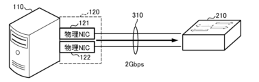
- a physical machine 110 and a network switch 210 are connected via a communication network 310.
- the physical machine 110 also has multiple physical NICs 121 and 122 as a communication interface 120. Similarly, there are multiple physical NICs on the network switch 210 side.
- the physical machine 110 bundles together multiple physical NICs 121 and 122, allowing the use of a single broadband link for communication between the physical machine 110 and the network switch 210.
- the two physical NICs 121 and 122 each have a communication performance of 1 Gbps, a single link with a communication performance of 2 Gbps can be used.
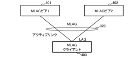
- multiple devices are connected to an MLAG client 403 via a communication network 320 that includes multiple switches and links that are bundled together using link aggregation.
- the MLAG client 403 can use multiple devices virtually as one device by switching between them.
- the device connected by an active link can be treated as a normal device (main device), and the device connected by an inactive link can be treated as a backup device. This makes it possible to quickly switch between the main device and the backup device in the event of a link or device failure.
- test packets P01, P02, ..., P0n, P11, P12, ..., P1n are normally communicated on the data plane between the session sender 102 and the session reflector 202, as shown in Figures 4 and 5.
- the receiver of each test packet can then measure the delay time (RTT), packet loss, jitter, number of hops, TTL (Time To Live), and processing time by updating the timestamp and sequence number.
- test packet transmission interval is constant.
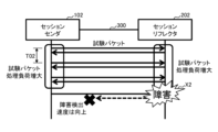
- Figure 4 shows an example of a communication state when the test packet transmission interval T01 is relatively large
- Figure 5 shows an example of a communication state when the test packet transmission interval T02 is relatively small.
- the test packet transmission interval T01 is large, so it takes a long time from when a failure X1 occurs until the session sender 102 detects the abnormality using test packets P1n.
- the test packet transmission interval T02 is small, so the time required from when a failure X2 occurs until the abnormality is detected using test packets is reduced.
- test packet transmission interval T02 because the test packet transmission interval T02 is short, the load on the session sender 102 for processing the test packets increases, which is expected to have a negative effect on processing other than the test packets.
- the load on the session reflector 202 for processing the test packets increases, which is expected to have a negative effect on processing other than the test packets.
- each test packet will be sent at the timings shown in Figures 6 and 7, in accordance with the provisions of IETF RFC4656, Sections 3.5 and 3.6.
- Figure 6 shows an example of "slot type 1" (fixed interval)
- Figure 7 shows an example of "slot type 0" (interval determined using exponentially distributed pseudorandom numbers).
- the request session message sent when establishing a test session includes the slot type and test packet transmission interval parameters.
- Type 0 indicates that exponentially distributed pseudo-random numbers are used, and type 1 indicates that a fixed amount is used.
- the test packet transmission interval parameter indicates a timestamp ( ⁇ Timestamp>).
- time slots SL1, SL2, ..., SLn appear in chronological order starting from start time t0, as shown in Figures 6 and 7.
- test packets Pt1, Pt2, ..., Ptm are transmitted when a certain time interval Ts has elapsed from the start time of each slot, as shown in Figure 6.
- test packets Pt1, Pt2, ..., Ptm are transmitted at time intervals Tx1, Tx2, ..., Txm from the start time of each slot.
- the size of each time interval Tx1, Tx2, ..., Txm is determined to be a time that is exponentially distributed with the average timestamp value. That is, in the example shown in FIG. 7, the transmission intervals of test packets Pt1, Pt2, ..., Ptm vary according to pseudo-random numbers.
- test packet transmission interval there is a trade-off between the test packet transmission interval and the software processing load. If test packets are sent frequently to prioritize anomaly detection, the software processing load of the node will increase. In particular, if abnormality detection on the backup route is delayed or not possible in a redundant configuration such as LAG, there is a risk of communication being cut off after route switching in the event of a fault on the main route. However, the above issues cannot be resolved using either of the controls shown in Figures 6 and 7.
- the present invention has been made in consideration of the above situation, and aims to provide a communication control device that performs data communication between two points, a first node and a second node, connected via a communication network, and that can appropriately transmit test packets in accordance with the operating status of the actual communication system when measuring the network performance between the two points by using a redundant communication path including a main path and a backup path.
- a communication control device of the present invention is a communication control device that can be used for data communication between a first node and a second node connected via a communication network, a communication unit corresponding to a communication path having a redundant configuration including a main path and a backup path; a test packet transmission unit for transmitting and receiving a predetermined test packet in order to measure the network performance in both directions between the two points; a transmission interval control unit that dynamically changes a transmission interval of the test packets on the main path and the backup path; The transmission interval control unit controls the transmission frequency of the test packets at least on the main path to be lower than the transmission frequency of the test packets on the backup path.
- data communication is performed between two points, a first node and a second node, which are connected via a communication network, and a redundant communication path including a main path and a backup path is used to measure the network performance between the two points, and test packets can be appropriately transmitted in accordance with the actual operating status of the communication system. That is, the frequency of transmission of the test packets on the main path is controlled to be lower than the frequency of transmission of the test packets on the backup path, so that the processing load on the main path associated with measuring the network performance of the node can be reduced and a decrease in performance of processes other than the network performance measurement can be prevented.
- FIG. 1 is a block diagram showing an example of the configuration of a communication system that uses the TWAMP protocol.
- FIG. 2 is a block diagram showing an example of the configuration of a communication system that uses link aggregation technology.
- FIG. 3 is a block diagram showing an example of the configuration of a communication system that uses the MLAG technology.
- FIG. 4 is a time chart showing an example 1 of a transmission operation of a test packet between a session sender and a session reflector when a protocol such as TWAMP is used.
- FIG. 5 is a time chart showing a second example of the transmission operation of a test packet between a session sender and a session reflector when a protocol such as TWAMP is used.
- FIG. 6 is a time chart showing example 1 of operation when sending test packets in accordance with the provisions of IETF RFC4656, Sections 3.5. and 3.6.
- Figure 7 is a time chart showing operation example 2 when sending test packets in accordance with the provisions of IETF RFC4656, Sections 3.5. and 3.6.
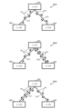
- FIG. 8 is a block diagram showing three types of operational examples of the communication system.
- FIG. 9 is a block diagram showing an example of the configuration of a physical machine and a communication system for implementing the present invention.
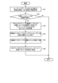
- FIG. 10 is a flowchart showing a first characteristic operational example of a physical machine embodying the present invention.
- FIG. 11 is a schematic diagram showing a specific example of a table used by a physical machine that performs the operation of FIG. FIG.
- FIG. 12 is a flowchart showing a second characteristic operational example of a physical machine embodying the present invention.
- FIG. 13 is a schematic diagram showing a specific example of a table used by a physical machine that performs the operation of FIG.
- FIG. 14 is a graph showing three types of examples of RTT changes.
- FIG. 15 is a flowchart showing a third characteristic operational example of a physical machine embodying the present invention.
- FIG. 16 is a schematic diagram showing a specific example of a table used by a physical machine that performs the operation of FIG.
- FIG. 8 The configuration and operation examples of three types of communication systems 500A, 500B, and 500C are shown in Fig. 8.
- Each of the communication systems 500A, 500B, and 500C shown in Fig. 8 has three nodes 501, 502, and 503.
- the nodes 501 and 502 are connected via a transmission path 511, and the nodes 501 and 503 are connected via a transmission path 512.
- data can be transmitted from the upstream node 501 to the user terminal via node 502, and data can also be transmitted from node 501 to the same user terminal via node 503.
- transmission path 511 is used as the main path (active system) and transmission path 512 is used as a backup path (standby system), and that in the event of a failure or the like, the active system and the standby system are switched for use.
- test packets Pt are transmitted in both directions between nodes 501 and 502, and further test packets Pt are transmitted in both directions between nodes 501 and 503.
- test packets Pt are transmitted in a general manner as shown in FIG. 6 or FIG. 7. Therefore, in communication system 500A, the transmission frequency of test packets Pt passing through transmission path 511 and the transmission frequency of test packets Pt passing through transmission path 512 are approximately equal.
- the transmission frequency of test packets Pt is dynamically controlled according to the situation to realize a more appropriate communication environment. Specifically, the transmission frequency of test packets Pt is controlled like the operation of communication systems 500B and 500C shown in FIG. 8.
- the communication system 500B shown in FIG. 8 uses the transmission path 511 connecting the nodes 501 and 502 as the main path (active system), and the transmission path 512 connecting the nodes 501 and 503 as the backup path (standby system).
- the transmission frequency of the test packets Pt on the transmission path 511, which is the main path is controlled to be lower than the transmission frequency of the test packets Pt on the transmission path 512, which is the backup path.
- the frequency with which test packets Pt are sent on the main route is low, reducing the processing load associated with measuring the network performance of the operational system and improving the processing performance of the operational system other than network performance measurement.
- the frequency with which test packets Pt are sent on the backup route is high, improving the network performance measurement function of the standby system, improving availability after switching between the operational and standby systems, and enabling early detection of failures.
- the transmission frequency of the test packets Pt in the active system is usually reduced from the standard value, and the transmission frequency of the test packets Pt in the standby system is increased from the standard value.
- the frequency of sending test packets Pt in the standby system is increased more than usual. This makes it easier to detect faults in the standby system early. Moreover, because only the standby system increases the frequency of sending test packets Pt, it is possible to avoid an increase in the processing load in the active system.
- transmission path 512 is switched from the standby system to the active system, and transmission path 511 is switched from the active system to the standby system.
- the frequency of sending test packets Pt on transmission path 512 is reduced in advance from the normal frequency.
- the multiple nodes 502 and 503 shown in FIG. 8 can also be housed in, for example, one physical machine.
- data communication is performed between two points, the first physical machine housing node 501, and the second physical machine housing the multiple nodes 502 and 503, via, for example, a specified gateway router.
- communication can be performed by switching the multiple transmission paths 511 and 512 between the active system and the standby system.
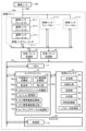
- FIG. 9 An example of the configuration of a physical machine and a communication system embodying the present invention is shown in Fig. 9.
- the physical machine 10A shown in Fig. 9 includes the function of the "communication control device" in the present invention.
- one physical machine 10A and another physical machine 10B are connected to each other via a communication network 300. Therefore, data communication can be performed between two points, a node on the physical machine 10A side and a node on the adjacent physical machine 10B side.
- the physical machine 10A shown in FIG. 9 includes multiple m physical interfaces 11-1, 11-2, ..., 11-m, communication buses 13, 14, a transmit packet processing unit 15, a receive packet processing unit 16, memory 17, a container engine 18, a virtualization container 19, and a host OS (operating system) 20. Also, the physical machine 10B in FIG. 9 includes the same components as the physical machine 10A. Note that in the drawings, interfaces are abbreviated as "IF.”
- Each of the physical interfaces 11-1 to 11-m is an independent physical NIC (network interface card) and can provide a physical function for communication using the communication network 300. Furthermore, the physical machine 10A can virtually allocate multiple n logical interfaces 12-1, 12-2, ..., 12-n to each of the physical interfaces 11-1 to 11-m. Furthermore, the physical machine 10A can bundle multiple physical interfaces 11-1 to 11-m and use them as one virtual NIC.
- NIC network interface card
- the links of the multiple transmission paths 511 and 512 shown in FIG. 8 can be used simultaneously, and the link of transmission path 511 can be assigned to the active system and the link of transmission path 512 can be assigned to the standby system, or the active system and the standby system can be switched. Also, in order to measure the network performance between two points of each of the multiple links, a test packet Pt can be transferred for each link as shown in FIG. 8.
- the transmission packet processing unit 15 in the physical machine 10A processes transmission packets.
- the reception packet processing unit 16 processes reception packets.
- the transmission packet processing unit 15 and the reception packet processing unit 16 can be used as the session sender 102 and the session reflector 202 shown in FIG. 1.
- the container engine 18 has the function of virtualizing OS resources for each container that serves as the development and execution environment for virtualized applications, and executing, operating, and managing the containers as if they were independent OSes. Specifically, it has the function of defining the slot schedule value for calculating the test packet transmission period required for OWAMP and TWAMP specified in the RFC, defining the "normal RTT value,” recording the "actual RTT value,” and calculating the RTT standard deviation.
- the container engine 18 includes a normal RTT definition unit 18a, a forwarding unit 18b, an RTT actual measurement value recording unit 18c, an insertion unit 18d, a slot schedule definition unit 18e, a session management unit 18f, an RTT standard deviation recording unit 18g, an RTT standard deviation calculation unit 18h, and a routing table recording unit 18i.
- the virtualization container 19 is a virtualized independent space in which an application environment, such as the main body and configuration files, is constructed. Specifically, it has the function of generating and transmitting test packets, and recording the transmission time of the test packets, which is necessary for calculating the RTT.
- the virtualization container 19 includes a generation unit 19a, an initialization unit 19b, a transmission unit 19c, an analysis unit 19d, a time recording unit 19e, and a parameter acquisition unit 19f.
- the host OS 20 is constructed by running software using an existing network OS.
- the control unit 21 in the host OS 20 has a function that allows multiple OSs to be used like applications. Specifically, it has a function to control the processing of received packets and transmitted packets.
- the data of the normal time RTT definition table TB11, the actual RTT value recording table TB12, and the slot schedule management table TB13 shown in FIG. 11 are stored in the normal time RTT definition section 18a, the actual RTT value recording section 18c, and the slot schedule definition section 18e of the container engine 18, respectively.
- the normal-time RTT definition table TB11 holds constant data for normal-time RTT (delay time) determined based on the results of prior measurement.
- the normal-time RTT definition table TB11 holds different constant data for each of multiple physical interface IDs and for each of multiple logical interface IDs.
- the LAG IDs are also held in the normal-time RTT definition table TB11.
- the RTT actual measurement value record table TB12 holds RTT data that indicates the actual measurement results.
- the actual RTT value is held for each measurement date and time, along with the physical interface ID, logical interface ID, and LAG ID.
- the data held in the RTT actual measurement value record table TB12 is updated each time the RTT is measured.
- the slot schedule management table TB13 holds multiple sets of constant data, each of which includes a schedule name, number of slots, parameters [ms], and type.
- different numbers of slots and parameter constants are registered for the slot schedule "Schedule1" of type "1" and the slot schedule "Schedule2" of type "0".
- the slot numbers, parameters, etc. in the slot schedule management table TB13 are appropriate constants calculated based on past actual RTT measurements, etc.
- step S11 the physical machine 10A acquires LAG-IDs representing specific links of the physical interfaces 11-1 to 11-m and logical interfaces 12-1 to 12-n to be controlled from the normal RTT definition table TB11. Specifically, the parameter acquisition unit 19f of the virtualization container 19 performs this process.
- step S12 the physical machine 10A acquires the parameters of the schedule "Schedule1" used when transmitting test packets at the normal frequency from the slot schedule management table TB13. Specifically, this process is performed by the parameter acquisition unit 19f of the virtualization container 19.
- step S13 the physical machine 10A assigns the specific physical interface 11 and the specific logical interface 12 associated with the LAG-ID of the link to the interface of the main route (active system) and establishes a communication session for transferring test packets of the active system.
- the analysis unit 19d of the virtualization container 19 determines the ID of the logical interface of the active system, and under the control of the container engine 18, the transmit packet processing unit 15 processes the test packets, and the receive packet processing unit 16 processes the receive packets.
- step S14 the physical machine 10A obtains the ID of the logical interface 12 with the lowest number other than the interface already assigned to the active system for the LAG-ID of the link from the normal RTT definition table TB11, and assigns this as the interface for the backup path (standby system).
- the container engine 18 extracts the logical interface ID from the normal RTT definition unit 18a, and the analysis unit 19d of the virtualization container 19 determines the interface for the standby system from the logical interface ID.
- step S15 the physical machine 10A acquires each parameter of the schedule "Schedule2" used to send test packets at a relatively high frequency from the slot schedule management table TB13.
- the parameter acquisition unit 19f of the virtualization container 19 acquires each parameter from the slot schedule definition unit 18e of the container engine 18.
- step S16 the physical machine 10A establishes a communication session for transferring test packets of the standby system, using the standby system interface assigned in step S14 and the parameters acquired in step S15.
- the analysis unit 19d of the virtualization container 19 determines the logical interface ID of the standby system interface, and under the control of the container engine 18, the transmit packet processing unit 15 processes the test packets, and the receive packet processing unit 16 processes the receive packets.
- step S17 the physical machine 10A specifies the acquired parameters in the request session packet from the previous step and transmits the request session packet. Specifically, the transmission packet processing unit 15 assigns the parameters acquired by the parameter acquisition unit 19f of the virtualization container 19 to the request session packet, and the transmission packet processing unit 15 transmits the request session packet.
- the transmission frequency of the active system and the standby system can be determined individually by the parameters of the low-frequency schedule "Schedule 1" and the high-frequency schedule "Schedule 2" when the physical machine 10A transmits a test packet. Therefore, for example, the transmission frequency of the active system of test packets Pt can be reduced and the transmission frequency of the standby system can be increased, as in the communication system 500B shown in FIG. 8.
- Control Example 2 A characteristic operation of "Control Example 2" in a physical machine implementing the present invention is shown in Fig. 12.
- a specific example of a table used by a physical machine implementing the operation of Fig. 12 is shown in Fig. 13.
- Graphs of three types of RTT change examples are shown in Fig. 14.
- the normal time RTT definition table TB21, the actual RTT value recording table TB22, the slot schedule management table TB23, and the RTT standard deviation management table TB24 shown in FIG. 13 are stored in the normal time RTT definition section 18a, the actual RTT value recording section 18c, the slot schedule definition section 18e, and the RTT standard deviation recording section 18g of the container engine 18, respectively.
- the contents of the normal RTT definition table TB21, the actual RTT value recording table TB22, and the slot schedule management table TB23 in FIG. 13 are the same as those of the tables in FIG. 11.
- the RTT standard deviation management table TB24 shown in FIG. 13 holds the actual RTT value standard deviation and its increment at each point in time calculated by the RTT standard deviation calculation unit 18h based on multiple actual RTT values, together with information on the date and time of the last actual RTT measurement.
- RTT change example G21 changes such as the three types of RTT change examples G21, G22, and G23 shown in Figure 14 are expected.
- the variation (standard deviation) of the actual RTT value is relatively small and the actual RTT value is below the threshold on average.
- RTT change example G21 corresponds to a situation in which communication quality is good.
- the variation in the actual RTT values is relatively small, and the actual RTT values exceed the threshold on average.
- the communication delay time is relatively large, RTT change example G22 corresponds to a situation in which communication quality is poor.
- the actual RTT values are below the threshold on average, but the variation in the actual RTT values is relatively large. Therefore, RTT change example G23 corresponds to a situation in which communication quality is poor.
- step S21 the physical machine 10A acquires the actual RTT value of the target interface in the most recent period T (a fixed length) from the actual RTT value recording table TB22.
- the RTT standard deviation calculation unit 18h of the container engine 18 acquires the actual RTT value from the RTT standard deviation recording unit 18g.
- step S22 the physical machine 10A calculates the average RTT (communication delay time) of the target interface in the most recent period T based on the multiple actual RTT values acquired in step S21.
- the result is obtained by dividing the sum of the actual RTT values acquired for period T by the number of data.
- the RTT standard deviation calculation unit 18h performs this calculation.
- step S23 the physical machine 10A obtains the normal RTT (communication delay time) of the target interface from the normal RTT definition table TB21.
- the analysis unit 19d of the virtualization container 19 obtains the normal RTT from the normal RTT definition unit 18a of the container engine 18.
- the analysis unit 19d of the virtualization container 19 obtains the average RTT (communication delay time) calculated one step before.
- step S24 the physical machine 10A compares the average RTT (communication delay time) obtained in step S22 for the target interface with the normal RTT (communication delay time) obtained in step S23. If the average RTT (communication delay time) is greater than the normal RTT (communication delay time), the process proceeds to step S29, and if this condition is not met, the process proceeds to step S25. Specifically, the analysis unit 19d of the virtualization container 19 performs this determination.
- step S25 the physical machine 10A calculates the deviation (difference) from the average RTT (communication delay time) for each of the acquired actual RTT values. Specifically, this calculation is performed by the RTT standard deviation calculation unit 18h of the container engine 18.
- step S26 the physical machine 10A derives the variance for all the acquired actual RTT values. In other words, it finds the result of dividing the "sum of the squared deviations of each actual RTT value" by the number of acquired RTTs. Specifically, this calculation is performed by the RTT standard deviation calculation unit 18h of the container engine 18.
- step S27 the physical machine 10A derives the standard deviation for all the acquired actual RTT values. In other words, it calculates the square root of the variance derived in step S26. Specifically, this calculation is performed by the RTT standard deviation calculation unit 18h of the container engine 18.
- step S28 the physical machine 10A identifies whether the variance obtained in step S26 has increased a predetermined number of times (N times) in succession. In other words, in step S28, it identifies whether the RTT (communication latency time) fluctuates significantly and the communication state is unstable. If this condition is met, the process proceeds to step S29, and if the condition is not met, the process returns to step S21. Specifically, the analysis unit 19d of the virtualization container 19 performs this determination.
- step S29 the physical machine 10A acquires each parameter of the schedule "Schedule2" used when transmitting test packets at a high frequency from the slot schedule management table TB23.
- the parameter acquisition unit 19f of the virtualization container 19 acquires each parameter from the slot schedule definition unit 18e of the container engine 18.
- step S30 the physical machine 10A sends a stop session packet through the standby interface and ends the test session.
- the analysis unit 19d of the virtualization container 19 determines the logical interface ID of the standby interface, and the transmission packet processing unit 15 sends the stop session packet.
- step S31 the physical machine 10A establishes a new test session with the standby interface.
- the analysis unit 19d of the virtualization container 19 determines the logical interface ID of the standby interface, and the transmission packet processing unit 15 transmits a new request session packet under the control of the container engine 18.
- step S32 the physical machine 10A specifies the acquired parameters in the request session packet from the previous step and transmits it. Specifically, the transmission packet processing unit 15 assigns the parameters acquired by the parameter acquisition unit 19f of the virtualization container 19 to the request session packet, and transmits this request session packet.
- step S24 when the physical machine 10A performs the operation shown in FIG. 12, if an RTT (communication delay time) change that differs from normal times occurs in the active system, this is detected in step S24, and the processing from step S29 onwards is executed. This increases the frequency of sending test packets in the standby system. Also, if the variation in RTT (communication delay time) becomes large, for example as in the RTT change example G23 in FIG. 14, this is detected in step S28, and the processing from step S29 onwards is executed. This increases the frequency of sending test packets in the standby system.
- RTT communication delay time
- the process may be modified so that the "moving average of actual RTT (communication delay time) values" is used instead of the “average RTT (communication delay time)” in each of steps S22 and S24 in FIG. 12.
- the transmission interval of the test packets is dynamically changed according to the increment of the standard deviation of the RTT (communication delay time) of the active route.
- Control Example 3 A characteristic operation of "Control Example 3" in a physical machine implementing the present invention is shown in Fig. 15. A concrete example of a table used by a physical machine implementing the operation of Fig. 15 is shown in Fig. 16.
- the routing table TB31 and slot schedule management table TB32 shown in FIG. 16 are stored in the routing table recording unit 18i and slot schedule definition unit 18e of the container engine 18, respectively.
- the routing table TB31 shown in FIG. 16 holds data on the item number, physical interface ID, route, next hop, and cost value for each of multiple route items.
- the slot schedule management table TB32 holds data on the schedule name, number of slots, parameter [ms], and type for each of multiple schedule items.
- the characteristic operations of the physical machine 10A shown in FIG. 15 will be described below.
- the physical machine 10A executes the operation shown in FIG. 15 when routing switching occurs.
- step S41 the physical machine 10A acquires information on each path of the active system and the standby system based on the contents of the routing table TB31.
- the physical interface ID associated with the LAG is searched for in the routing table TB31, and the cost value of the interface of each path is obtained from the contents of the routing table TB31.
- step S42 the physical machine 10A identifies whether the target interface is a standby route. Specifically, the analysis unit 19d of the virtualization container 19 regards the interface with the lower cost value acquired in step S31 as the active route and the interface with the higher cost value as the standby route, out of the two routes, active and standby, linked to the same LAG. Then, the process proceeds to step S43 and subsequent steps only when processing the standby route.
- step S43 the physical machine 10A acquires each parameter of the schedule "Schedule3" prepared for sending test packets at a low frequency from the slot schedule management table TB32. Specifically, the parameter acquisition unit 19f of the virtualization container 19 acquires each parameter of the low-frequency schedule "Schedule3" from the slot schedule definition unit 18e of the container engine 18.
- step S44 the physical machine 10A uses the interface of the standby system path to transmit a stop session packet and terminate the test session. Specifically, based on the result of the determination made by the analysis unit 19d of the virtualization container 19, the transmission packet processing unit 15 transmits a stop session packet using the interface of the standby system path.
- step S45 the physical machine 10A establishes a new test session using the interface of the standby system route. Specifically, based on the result of the determination made by the analysis unit 19d of the virtualization container 19, the transmission packet processing unit 15 transmits a request session packet using the interface of the standby system route.
- step S46 the physical machine 10A specifies the acquired parameters in the request session packet from the previous step and transmits it. Specifically, the transmission packet processing unit 15 assigns the parameters acquired by the parameter acquisition unit 19f of the virtualization container 19 to the request session packet and transmits it via the interface of the standby system route.
- the physical machine 10A executes the process shown in FIG. 15 in advance when switching routing, thereby reducing the frequency of test packet transmissions on the standby route before switching.
- the parameter changes from "60000 [ms]” to "90000 [ms]” and the type also changes, so that the frequency of test packet transmissions on the standby route decreases.
- the frequency of sending test packets Pt on the transmission path 512 decreases. Therefore, the routing process on the transmission path 512, which becomes the new active system after the route switching, can be given priority over the processing of test packets.
- the load on the standby system (active system after switching) for that process decreases, making it easier to smoothly execute the routing process associated with the route switching.
- a communication control device (physical machine 10A) that can be used for data communication between a first node and a second node that are connected via a communication network, a communication unit (physical interfaces 11-1 to 11-m) corresponding to a communication path having a redundant configuration including a main path (operational system) and a backup path (standby system); a test packet transmission unit (transmission packet processing unit 15) for transmitting and receiving predetermined test packets in order to measure the network performance in both directions between the two points; a transmission interval control unit (virtualization container 19) that dynamically changes the transmission intervals of the test packets on the main path and the backup path; the transmission interval control unit controls at least the transmission frequency of the test packets on the main path to be lower than the transmission frequency of the test packets on the backup path (S11 to S17).
- the communication control device having the configuration of [1] above can increase the frequency of test packet transmission on the backup route while keeping the frequency of test packet transmission on the main route low. In other words, by maintaining the frequency of test packet transmission on the main route low, it is possible to reduce the load that test packets place on the processing of the main route and the network resources consumed by transmitting test packets. Furthermore, by increasing the frequency of test packet transmission on the backup route, it becomes possible to detect the occurrence of a fault on the backup route early. Furthermore, it is possible to improve availability after route switching.
- the transmission interval control unit has a schedule management table (slot schedule management table TB13) that separately holds a first constant that affects the transmission frequency of the test packet on the main path and a second constant that affects the transmission frequency of the test packet on the backup path.
- schedule management table TB13 schedule management table that separately holds a first constant that affects the transmission frequency of the test packet on the main path and a second constant that affects the transmission frequency of the test packet on the backup path.
- the communication control device with the configuration of [2] above can determine the appropriate transmission frequency of test packets for each of the main path and the backup path using a predetermined constant, thereby reducing the processing load associated with sending test packets.
- the transmission interval control unit detects a change in the RTT of the main route that is different from a normal time, the transmission interval control unit increases only the transmission frequency of the test packets on the backup route (S21 to S32).
- the communication control device according to [1] above.
- the communication control device with the configuration of [3] above makes it easy to ensure a stable communication path.
- the delay time RTT on the main path increases on average, or when the variance in the delay time RTT increases, the communication quality of the main path is poor, so it is expected that there is a high possibility that the path used for normal communication will be switched from the main path to the backup path.
- the frequency of sending test packets on the backup path it becomes possible to detect the occurrence of a fault on the backup path early, and availability after the path switching can be improved.
- the transmission interval control unit temporarily reduces the transmission frequency of the test packets on the backup route compared to a normal transmission frequency (S41 to S46).
- the frequency of sending the test packets on the backup route decreases. This makes it possible to reduce the load that the test packets place on the processing of the backup route and the network resources consumed in transmitting the test packets. As a result, the reduced processing load and network resources consumed increase the capacity to execute other processes such as routing, making it possible to process route switching operations smoothly.
Landscapes
- Health & Medical Sciences (AREA)
- Cardiology (AREA)
- General Health & Medical Sciences (AREA)
- Engineering & Computer Science (AREA)
- Computer Networks & Wireless Communication (AREA)
- Signal Processing (AREA)
- Data Exchanges In Wide-Area Networks (AREA)
Abstract
Dans la présente invention, lorsqu'une communication est effectuée entre deux nœuds à l'aide d'un trajet principal (système actif) et d'un trajet de sauvegarde (système de secours), et que la performance de réseau de chacun des trajets est déterminée par la transmission de paquets de test, une augmentation de la charge de traitement en raison de la transmission de paquets de test et l'apparition d'une interruption de communication en raison d'un retard de détection de défaillance sont empêchées. La fréquence de transmission de paquets de test du système actif et la fréquence de transmission de paquets de test du système de secours sont commandées individuellement et dynamiquement. La fréquence de transmission de paquets de test du système actif est réglée pour être inférieure à la fréquence de transmission de paquets de test du système de secours. Des constantes des fréquences de transmission du système actif et du système de secours sont gérées à l'aide d'une table de gestion de programmation de créneaux. La fréquence de transmission de paquets de test du système de secours est augmentée lorsqu'un changement de RTT différent d'un temps normal est détecté dans le système actif. Lorsqu'une commutation de routage se produit, la fréquence de transmission de paquets de test du système de secours est réduite à l'avance de telle sorte que le traitement de routage peut être effectué en priorité.
Priority Applications (2)
| Application Number | Priority Date | Filing Date | Title |
|---|---|---|---|
| PCT/JP2023/030054 WO2025041239A1 (fr) | 2023-08-21 | 2023-08-21 | Dispositif de commande de communication |
| JP2025541195A JPWO2025041239A1 (fr) | 2023-08-21 | 2023-08-21 |
Applications Claiming Priority (1)
| Application Number | Priority Date | Filing Date | Title |
|---|---|---|---|
| PCT/JP2023/030054 WO2025041239A1 (fr) | 2023-08-21 | 2023-08-21 | Dispositif de commande de communication |
Publications (1)
| Publication Number | Publication Date |
|---|---|
| WO2025041239A1 true WO2025041239A1 (fr) | 2025-02-27 |
Family
ID=94731858
Family Applications (1)
| Application Number | Title | Priority Date | Filing Date |
|---|---|---|---|
| PCT/JP2023/030054 Pending WO2025041239A1 (fr) | 2023-08-21 | 2023-08-21 | Dispositif de commande de communication |
Country Status (2)
| Country | Link |
|---|---|
| JP (1) | JPWO2025041239A1 (fr) |
| WO (1) | WO2025041239A1 (fr) |
Citations (3)
| Publication number | Priority date | Publication date | Assignee | Title |
|---|---|---|---|---|
| JP2011518512A (ja) * | 2008-04-16 | 2011-06-23 | テレフオンアクチーボラゲット エル エム エリクソン(パブル) | 接続障害管理におけるトラフィック指示の拡張 |
| JP2012205286A (ja) * | 2011-03-28 | 2012-10-22 | Ntt Communications Kk | ネットワーク監視装置、ネットワーク試験方法、パス情報管理方法、及びプログラム |
| JP2017060136A (ja) * | 2015-09-18 | 2017-03-23 | 富士通株式会社 | ネットワーク診断システムおよびネットワーク診断方法 |
-
2023
- 2023-08-21 WO PCT/JP2023/030054 patent/WO2025041239A1/fr active Pending
- 2023-08-21 JP JP2025541195A patent/JPWO2025041239A1/ja active Pending
Patent Citations (3)
| Publication number | Priority date | Publication date | Assignee | Title |
|---|---|---|---|---|
| JP2011518512A (ja) * | 2008-04-16 | 2011-06-23 | テレフオンアクチーボラゲット エル エム エリクソン(パブル) | 接続障害管理におけるトラフィック指示の拡張 |
| JP2012205286A (ja) * | 2011-03-28 | 2012-10-22 | Ntt Communications Kk | ネットワーク監視装置、ネットワーク試験方法、パス情報管理方法、及びプログラム |
| JP2017060136A (ja) * | 2015-09-18 | 2017-03-23 | 富士通株式会社 | ネットワーク診断システムおよびネットワーク診断方法 |
Also Published As
| Publication number | Publication date |
|---|---|
| JPWO2025041239A1 (fr) | 2025-02-27 |
Similar Documents
| Publication | Publication Date | Title |
|---|---|---|
| JP4840236B2 (ja) | ネットワークシステム及びノード装置 | |
| US10785117B2 (en) | Methods and apparatus for configuring a standby WAN link in an adaptive private network | |
| US8661116B2 (en) | Network testing | |
| US10785093B2 (en) | Monitoring and detecting causes of failures of network paths | |
| EP2671352B1 (fr) | Système et procédé d'agrégation et d'estimation de bande passante de plusieurs interfaces réseau | |
| US9385944B2 (en) | Communication system, path switching method and communication device | |
| EP3219060B1 (fr) | Équilibrage de charge selon les circuits avec qualité de service dynamique | |
| US20160072706A1 (en) | Adaptive Private Network with Dynamic Conduit Process | |
| US7957330B1 (en) | Failsafe management of periodic communications during system upgrade for a network device | |
| CN109075996B (zh) | 用于监视网络性能的监视控制器及因此执行的方法 | |
| JP2000049858A (ja) | 通信システム | |
| CN100558046C (zh) | 一种对虚拟路由器冗余协议备份组进行管理的方法 | |
| US8428072B2 (en) | Methods and apparatus for advertising a route for transmitting data packets | |
| Reda et al. | Path persistence in the cloud: A study of the effects of inter-region traffic engineering in a large cloud provider's network | |
| US7974188B2 (en) | Repeater and communication method | |
| US20120117246A1 (en) | Method And System For The Efficient And Automated Management of Virtual Networks | |
| Xhonneux et al. | Flexible failure detection and fast reroute using eBPF and SRv6 | |
| JP4532253B2 (ja) | フレーム転送装置及びフレームのループ抑止方法 | |
| US20150381498A1 (en) | Network system and its load distribution method | |
| JP4559512B2 (ja) | パケット転送システムおよびパケット転送方法 | |
| Hassan et al. | Performance Evaluation of Bidirectional Forwarding Detection (BFD) over the Virtual Router Redundancy Protocol (VRRP) | |
| CN116208547B (zh) | 一种报文传输方法及装置 | |
| CN118803089A (zh) | 双通道数据传输方法和装置、计算机设备和存储介质 | |
| Holzinger et al. | SmartNIC-based load management and network health monitoring for time sensitive applications | |
| Zhang et al. | A Low-Overhead and Real-Time Service Recovery Mechanism for Data Center Networks with SDN |
Legal Events
| Date | Code | Title | Description |
|---|---|---|---|
| 121 | Ep: the epo has been informed by wipo that ep was designated in this application |
Ref document number: 23949700 Country of ref document: EP Kind code of ref document: A1 |
|
| ENP | Entry into the national phase |
Ref document number: 2025541195 Country of ref document: JP Kind code of ref document: A |
|
| WWE | Wipo information: entry into national phase |
Ref document number: 2025541195 Country of ref document: JP |
|
| NENP | Non-entry into the national phase |
Ref country code: DE |