WO2025041239A1 - 通信制御装置 - Google Patents
通信制御装置 Download PDFInfo
- Publication number
- WO2025041239A1 WO2025041239A1 PCT/JP2023/030054 JP2023030054W WO2025041239A1 WO 2025041239 A1 WO2025041239 A1 WO 2025041239A1 JP 2023030054 W JP2023030054 W JP 2023030054W WO 2025041239 A1 WO2025041239 A1 WO 2025041239A1
- Authority
- WO
- WIPO (PCT)
- Prior art keywords
- communication
- transmission
- rtt
- test packets
- path
- Prior art date
- Legal status (The legal status is an assumption and is not a legal conclusion. Google has not performed a legal analysis and makes no representation as to the accuracy of the status listed.)
- Pending
Links
Images







Classifications
-
- H—ELECTRICITY
- H04—ELECTRIC COMMUNICATION TECHNIQUE
- H04L—TRANSMISSION OF DIGITAL INFORMATION, e.g. TELEGRAPHIC COMMUNICATION
- H04L43/00—Arrangements for monitoring or testing data switching networks
- H04L43/10—Active monitoring, e.g. heartbeat, ping or trace-route
- H04L43/103—Active monitoring, e.g. heartbeat, ping or trace-route with adaptive polling, i.e. dynamically adapting the polling rate
Definitions
- the present invention relates to a communication control device that can be used for data communication between two points, a first node and a second node, connected via a communication network, and in particular to a communication control device that supports a redundant communication path including a main path and a backup path and has a function for measuring the network performance between the two points.
- various communication equipment used in the fifth generation mobile communication system needs to realize ultra-high speed, large volume data communication over various communication networks. Also, to maintain a stable communication state between two points on a communication network, it is necessary to measure the network performance in both directions between these two points.
- Protocols used to measure such network performance include TWAMP (Two-Way Active Measurement Protocol) disclosed in Non-Patent Document 1, STAMP (Simple Two-Way Active Measurement Protocol IETF RFC 8762), and OWAMP (A One-Way Active Measurement Protocol).
- TWAMP Tro-Way Active Measurement Protocol
- STAMP Simple Two-Way Active Measurement Protocol IETF RFC 8762
- OWAMP A One-Way Active Measurement Protocol
- network performance is measured at the application layer, making them useful for measuring the performance of real-time applications such as voice and video.
- LAG link aggregation
- Patent Document 1 a technology for a mobile terminal is known that variably controls the polling interval of a transceiver based on the presence or absence of spatial movement of the mobile terminal detected by a motion sensor.
- two devices (A, B) 100, 200 are prepared and connected via a communication network 300.
- Device 100 has a control client 101 and a session sender 102 as a TWAMP controller.
- Device 200 has a server 201 and a session reflector 202 as a TWAMP responder.
- TWAMP-Control In the TWAMP protocol, first, in communication between the control client 101 and the server 201 (TWAMP-Control), a connection between the two devices 100, 200 is set up. Secondly, in communication between the session sender 102 and the session reflector 202 (TWAMP-Test), the session sender 102 sends and receives UDP test packets. After the session reflector 202 receives the UDP test packets, it replies with a measurement packet. Finally, in communication between the control client 101 and the server 201 (TWAMP-Control), the connection is terminated.
- TWAMP-Control In the TWAMP protocol, first, in communication between the control client 101 and the server 201 (TWAMP-Control), a connection between the two devices 100, 200 is set up. Secondly, in communication between the session sender 102 and the session reflector 202 (TWAMP-Test), the session sender 102 sends and receives UDP test packets. After the session reflector 202 receives the UDP test packets, it replies with
- a communication system with a configuration as shown in FIG. 2 is used.
- a physical machine 110 and a network switch 210 are connected via a communication network 310.
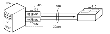
- the physical machine 110 also has multiple physical NICs 121 and 122 as a communication interface 120. Similarly, there are multiple physical NICs on the network switch 210 side.
- the physical machine 110 bundles together multiple physical NICs 121 and 122, allowing the use of a single broadband link for communication between the physical machine 110 and the network switch 210.
- the two physical NICs 121 and 122 each have a communication performance of 1 Gbps, a single link with a communication performance of 2 Gbps can be used.
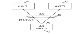
- multiple devices are connected to an MLAG client 403 via a communication network 320 that includes multiple switches and links that are bundled together using link aggregation.
- the MLAG client 403 can use multiple devices virtually as one device by switching between them.
- the device connected by an active link can be treated as a normal device (main device), and the device connected by an inactive link can be treated as a backup device. This makes it possible to quickly switch between the main device and the backup device in the event of a link or device failure.
- test packets P01, P02, ..., P0n, P11, P12, ..., P1n are normally communicated on the data plane between the session sender 102 and the session reflector 202, as shown in Figures 4 and 5.
- the receiver of each test packet can then measure the delay time (RTT), packet loss, jitter, number of hops, TTL (Time To Live), and processing time by updating the timestamp and sequence number.
- test packet transmission interval is constant.
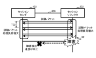
- Figure 4 shows an example of a communication state when the test packet transmission interval T01 is relatively large
- Figure 5 shows an example of a communication state when the test packet transmission interval T02 is relatively small.
- the test packet transmission interval T01 is large, so it takes a long time from when a failure X1 occurs until the session sender 102 detects the abnormality using test packets P1n.
- the test packet transmission interval T02 is small, so the time required from when a failure X2 occurs until the abnormality is detected using test packets is reduced.
- test packet transmission interval T02 because the test packet transmission interval T02 is short, the load on the session sender 102 for processing the test packets increases, which is expected to have a negative effect on processing other than the test packets.
- the load on the session reflector 202 for processing the test packets increases, which is expected to have a negative effect on processing other than the test packets.
- each test packet will be sent at the timings shown in Figures 6 and 7, in accordance with the provisions of IETF RFC4656, Sections 3.5 and 3.6.
- Figure 6 shows an example of "slot type 1" (fixed interval)
- Figure 7 shows an example of "slot type 0" (interval determined using exponentially distributed pseudorandom numbers).
- the request session message sent when establishing a test session includes the slot type and test packet transmission interval parameters.
- Type 0 indicates that exponentially distributed pseudo-random numbers are used, and type 1 indicates that a fixed amount is used.
- the test packet transmission interval parameter indicates a timestamp ( ⁇ Timestamp>).
- time slots SL1, SL2, ..., SLn appear in chronological order starting from start time t0, as shown in Figures 6 and 7.
- test packets Pt1, Pt2, ..., Ptm are transmitted when a certain time interval Ts has elapsed from the start time of each slot, as shown in Figure 6.
- test packets Pt1, Pt2, ..., Ptm are transmitted at time intervals Tx1, Tx2, ..., Txm from the start time of each slot.
- the size of each time interval Tx1, Tx2, ..., Txm is determined to be a time that is exponentially distributed with the average timestamp value. That is, in the example shown in FIG. 7, the transmission intervals of test packets Pt1, Pt2, ..., Ptm vary according to pseudo-random numbers.
- test packet transmission interval there is a trade-off between the test packet transmission interval and the software processing load. If test packets are sent frequently to prioritize anomaly detection, the software processing load of the node will increase. In particular, if abnormality detection on the backup route is delayed or not possible in a redundant configuration such as LAG, there is a risk of communication being cut off after route switching in the event of a fault on the main route. However, the above issues cannot be resolved using either of the controls shown in Figures 6 and 7.
- the present invention has been made in consideration of the above situation, and aims to provide a communication control device that performs data communication between two points, a first node and a second node, connected via a communication network, and that can appropriately transmit test packets in accordance with the operating status of the actual communication system when measuring the network performance between the two points by using a redundant communication path including a main path and a backup path.
- a communication control device of the present invention is a communication control device that can be used for data communication between a first node and a second node connected via a communication network, a communication unit corresponding to a communication path having a redundant configuration including a main path and a backup path; a test packet transmission unit for transmitting and receiving a predetermined test packet in order to measure the network performance in both directions between the two points; a transmission interval control unit that dynamically changes a transmission interval of the test packets on the main path and the backup path; The transmission interval control unit controls the transmission frequency of the test packets at least on the main path to be lower than the transmission frequency of the test packets on the backup path.
- data communication is performed between two points, a first node and a second node, which are connected via a communication network, and a redundant communication path including a main path and a backup path is used to measure the network performance between the two points, and test packets can be appropriately transmitted in accordance with the actual operating status of the communication system. That is, the frequency of transmission of the test packets on the main path is controlled to be lower than the frequency of transmission of the test packets on the backup path, so that the processing load on the main path associated with measuring the network performance of the node can be reduced and a decrease in performance of processes other than the network performance measurement can be prevented.
- FIG. 1 is a block diagram showing an example of the configuration of a communication system that uses the TWAMP protocol.
- FIG. 2 is a block diagram showing an example of the configuration of a communication system that uses link aggregation technology.
- FIG. 3 is a block diagram showing an example of the configuration of a communication system that uses the MLAG technology.
- FIG. 4 is a time chart showing an example 1 of a transmission operation of a test packet between a session sender and a session reflector when a protocol such as TWAMP is used.
- FIG. 5 is a time chart showing a second example of the transmission operation of a test packet between a session sender and a session reflector when a protocol such as TWAMP is used.
- FIG. 6 is a time chart showing example 1 of operation when sending test packets in accordance with the provisions of IETF RFC4656, Sections 3.5. and 3.6.
- Figure 7 is a time chart showing operation example 2 when sending test packets in accordance with the provisions of IETF RFC4656, Sections 3.5. and 3.6.
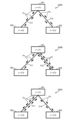
- FIG. 8 is a block diagram showing three types of operational examples of the communication system.
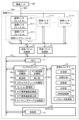
- FIG. 9 is a block diagram showing an example of the configuration of a physical machine and a communication system for implementing the present invention.
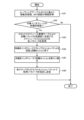
- FIG. 10 is a flowchart showing a first characteristic operational example of a physical machine embodying the present invention.
- FIG. 11 is a schematic diagram showing a specific example of a table used by a physical machine that performs the operation of FIG. FIG.
- FIG. 12 is a flowchart showing a second characteristic operational example of a physical machine embodying the present invention.
- FIG. 13 is a schematic diagram showing a specific example of a table used by a physical machine that performs the operation of FIG.
- FIG. 14 is a graph showing three types of examples of RTT changes.
- FIG. 15 is a flowchart showing a third characteristic operational example of a physical machine embodying the present invention.
- FIG. 16 is a schematic diagram showing a specific example of a table used by a physical machine that performs the operation of FIG.
- FIG. 8 The configuration and operation examples of three types of communication systems 500A, 500B, and 500C are shown in Fig. 8.
- Each of the communication systems 500A, 500B, and 500C shown in Fig. 8 has three nodes 501, 502, and 503.
- the nodes 501 and 502 are connected via a transmission path 511, and the nodes 501 and 503 are connected via a transmission path 512.
- data can be transmitted from the upstream node 501 to the user terminal via node 502, and data can also be transmitted from node 501 to the same user terminal via node 503.
- transmission path 511 is used as the main path (active system) and transmission path 512 is used as a backup path (standby system), and that in the event of a failure or the like, the active system and the standby system are switched for use.
- test packets Pt are transmitted in both directions between nodes 501 and 502, and further test packets Pt are transmitted in both directions between nodes 501 and 503.
- test packets Pt are transmitted in a general manner as shown in FIG. 6 or FIG. 7. Therefore, in communication system 500A, the transmission frequency of test packets Pt passing through transmission path 511 and the transmission frequency of test packets Pt passing through transmission path 512 are approximately equal.
- the transmission frequency of test packets Pt is dynamically controlled according to the situation to realize a more appropriate communication environment. Specifically, the transmission frequency of test packets Pt is controlled like the operation of communication systems 500B and 500C shown in FIG. 8.
- the communication system 500B shown in FIG. 8 uses the transmission path 511 connecting the nodes 501 and 502 as the main path (active system), and the transmission path 512 connecting the nodes 501 and 503 as the backup path (standby system).
- the transmission frequency of the test packets Pt on the transmission path 511, which is the main path is controlled to be lower than the transmission frequency of the test packets Pt on the transmission path 512, which is the backup path.
- the frequency with which test packets Pt are sent on the main route is low, reducing the processing load associated with measuring the network performance of the operational system and improving the processing performance of the operational system other than network performance measurement.
- the frequency with which test packets Pt are sent on the backup route is high, improving the network performance measurement function of the standby system, improving availability after switching between the operational and standby systems, and enabling early detection of failures.
- the transmission frequency of the test packets Pt in the active system is usually reduced from the standard value, and the transmission frequency of the test packets Pt in the standby system is increased from the standard value.
- the frequency of sending test packets Pt in the standby system is increased more than usual. This makes it easier to detect faults in the standby system early. Moreover, because only the standby system increases the frequency of sending test packets Pt, it is possible to avoid an increase in the processing load in the active system.
- transmission path 512 is switched from the standby system to the active system, and transmission path 511 is switched from the active system to the standby system.
- the frequency of sending test packets Pt on transmission path 512 is reduced in advance from the normal frequency.
- the multiple nodes 502 and 503 shown in FIG. 8 can also be housed in, for example, one physical machine.
- data communication is performed between two points, the first physical machine housing node 501, and the second physical machine housing the multiple nodes 502 and 503, via, for example, a specified gateway router.
- communication can be performed by switching the multiple transmission paths 511 and 512 between the active system and the standby system.
- FIG. 9 An example of the configuration of a physical machine and a communication system embodying the present invention is shown in Fig. 9.
- the physical machine 10A shown in Fig. 9 includes the function of the "communication control device" in the present invention.
- one physical machine 10A and another physical machine 10B are connected to each other via a communication network 300. Therefore, data communication can be performed between two points, a node on the physical machine 10A side and a node on the adjacent physical machine 10B side.
- the physical machine 10A shown in FIG. 9 includes multiple m physical interfaces 11-1, 11-2, ..., 11-m, communication buses 13, 14, a transmit packet processing unit 15, a receive packet processing unit 16, memory 17, a container engine 18, a virtualization container 19, and a host OS (operating system) 20. Also, the physical machine 10B in FIG. 9 includes the same components as the physical machine 10A. Note that in the drawings, interfaces are abbreviated as "IF.”
- Each of the physical interfaces 11-1 to 11-m is an independent physical NIC (network interface card) and can provide a physical function for communication using the communication network 300. Furthermore, the physical machine 10A can virtually allocate multiple n logical interfaces 12-1, 12-2, ..., 12-n to each of the physical interfaces 11-1 to 11-m. Furthermore, the physical machine 10A can bundle multiple physical interfaces 11-1 to 11-m and use them as one virtual NIC.
- NIC network interface card
- the links of the multiple transmission paths 511 and 512 shown in FIG. 8 can be used simultaneously, and the link of transmission path 511 can be assigned to the active system and the link of transmission path 512 can be assigned to the standby system, or the active system and the standby system can be switched. Also, in order to measure the network performance between two points of each of the multiple links, a test packet Pt can be transferred for each link as shown in FIG. 8.
- the transmission packet processing unit 15 in the physical machine 10A processes transmission packets.
- the reception packet processing unit 16 processes reception packets.
- the transmission packet processing unit 15 and the reception packet processing unit 16 can be used as the session sender 102 and the session reflector 202 shown in FIG. 1.
- the container engine 18 has the function of virtualizing OS resources for each container that serves as the development and execution environment for virtualized applications, and executing, operating, and managing the containers as if they were independent OSes. Specifically, it has the function of defining the slot schedule value for calculating the test packet transmission period required for OWAMP and TWAMP specified in the RFC, defining the "normal RTT value,” recording the "actual RTT value,” and calculating the RTT standard deviation.
- the container engine 18 includes a normal RTT definition unit 18a, a forwarding unit 18b, an RTT actual measurement value recording unit 18c, an insertion unit 18d, a slot schedule definition unit 18e, a session management unit 18f, an RTT standard deviation recording unit 18g, an RTT standard deviation calculation unit 18h, and a routing table recording unit 18i.
- the virtualization container 19 is a virtualized independent space in which an application environment, such as the main body and configuration files, is constructed. Specifically, it has the function of generating and transmitting test packets, and recording the transmission time of the test packets, which is necessary for calculating the RTT.
- the virtualization container 19 includes a generation unit 19a, an initialization unit 19b, a transmission unit 19c, an analysis unit 19d, a time recording unit 19e, and a parameter acquisition unit 19f.
- the host OS 20 is constructed by running software using an existing network OS.
- the control unit 21 in the host OS 20 has a function that allows multiple OSs to be used like applications. Specifically, it has a function to control the processing of received packets and transmitted packets.
- the data of the normal time RTT definition table TB11, the actual RTT value recording table TB12, and the slot schedule management table TB13 shown in FIG. 11 are stored in the normal time RTT definition section 18a, the actual RTT value recording section 18c, and the slot schedule definition section 18e of the container engine 18, respectively.
- the normal-time RTT definition table TB11 holds constant data for normal-time RTT (delay time) determined based on the results of prior measurement.
- the normal-time RTT definition table TB11 holds different constant data for each of multiple physical interface IDs and for each of multiple logical interface IDs.
- the LAG IDs are also held in the normal-time RTT definition table TB11.
- the RTT actual measurement value record table TB12 holds RTT data that indicates the actual measurement results.
- the actual RTT value is held for each measurement date and time, along with the physical interface ID, logical interface ID, and LAG ID.
- the data held in the RTT actual measurement value record table TB12 is updated each time the RTT is measured.
- the slot schedule management table TB13 holds multiple sets of constant data, each of which includes a schedule name, number of slots, parameters [ms], and type.
- different numbers of slots and parameter constants are registered for the slot schedule "Schedule1" of type "1" and the slot schedule "Schedule2" of type "0".
- the slot numbers, parameters, etc. in the slot schedule management table TB13 are appropriate constants calculated based on past actual RTT measurements, etc.
- step S11 the physical machine 10A acquires LAG-IDs representing specific links of the physical interfaces 11-1 to 11-m and logical interfaces 12-1 to 12-n to be controlled from the normal RTT definition table TB11. Specifically, the parameter acquisition unit 19f of the virtualization container 19 performs this process.
- step S12 the physical machine 10A acquires the parameters of the schedule "Schedule1" used when transmitting test packets at the normal frequency from the slot schedule management table TB13. Specifically, this process is performed by the parameter acquisition unit 19f of the virtualization container 19.
- step S13 the physical machine 10A assigns the specific physical interface 11 and the specific logical interface 12 associated with the LAG-ID of the link to the interface of the main route (active system) and establishes a communication session for transferring test packets of the active system.
- the analysis unit 19d of the virtualization container 19 determines the ID of the logical interface of the active system, and under the control of the container engine 18, the transmit packet processing unit 15 processes the test packets, and the receive packet processing unit 16 processes the receive packets.
- step S14 the physical machine 10A obtains the ID of the logical interface 12 with the lowest number other than the interface already assigned to the active system for the LAG-ID of the link from the normal RTT definition table TB11, and assigns this as the interface for the backup path (standby system).
- the container engine 18 extracts the logical interface ID from the normal RTT definition unit 18a, and the analysis unit 19d of the virtualization container 19 determines the interface for the standby system from the logical interface ID.
- step S15 the physical machine 10A acquires each parameter of the schedule "Schedule2" used to send test packets at a relatively high frequency from the slot schedule management table TB13.
- the parameter acquisition unit 19f of the virtualization container 19 acquires each parameter from the slot schedule definition unit 18e of the container engine 18.
- step S16 the physical machine 10A establishes a communication session for transferring test packets of the standby system, using the standby system interface assigned in step S14 and the parameters acquired in step S15.
- the analysis unit 19d of the virtualization container 19 determines the logical interface ID of the standby system interface, and under the control of the container engine 18, the transmit packet processing unit 15 processes the test packets, and the receive packet processing unit 16 processes the receive packets.
- step S17 the physical machine 10A specifies the acquired parameters in the request session packet from the previous step and transmits the request session packet. Specifically, the transmission packet processing unit 15 assigns the parameters acquired by the parameter acquisition unit 19f of the virtualization container 19 to the request session packet, and the transmission packet processing unit 15 transmits the request session packet.
- the transmission frequency of the active system and the standby system can be determined individually by the parameters of the low-frequency schedule "Schedule 1" and the high-frequency schedule "Schedule 2" when the physical machine 10A transmits a test packet. Therefore, for example, the transmission frequency of the active system of test packets Pt can be reduced and the transmission frequency of the standby system can be increased, as in the communication system 500B shown in FIG. 8.
- Control Example 2 A characteristic operation of "Control Example 2" in a physical machine implementing the present invention is shown in Fig. 12.
- a specific example of a table used by a physical machine implementing the operation of Fig. 12 is shown in Fig. 13.
- Graphs of three types of RTT change examples are shown in Fig. 14.
- the normal time RTT definition table TB21, the actual RTT value recording table TB22, the slot schedule management table TB23, and the RTT standard deviation management table TB24 shown in FIG. 13 are stored in the normal time RTT definition section 18a, the actual RTT value recording section 18c, the slot schedule definition section 18e, and the RTT standard deviation recording section 18g of the container engine 18, respectively.
- the contents of the normal RTT definition table TB21, the actual RTT value recording table TB22, and the slot schedule management table TB23 in FIG. 13 are the same as those of the tables in FIG. 11.
- the RTT standard deviation management table TB24 shown in FIG. 13 holds the actual RTT value standard deviation and its increment at each point in time calculated by the RTT standard deviation calculation unit 18h based on multiple actual RTT values, together with information on the date and time of the last actual RTT measurement.
- RTT change example G21 changes such as the three types of RTT change examples G21, G22, and G23 shown in Figure 14 are expected.
- the variation (standard deviation) of the actual RTT value is relatively small and the actual RTT value is below the threshold on average.
- RTT change example G21 corresponds to a situation in which communication quality is good.
- the variation in the actual RTT values is relatively small, and the actual RTT values exceed the threshold on average.
- the communication delay time is relatively large, RTT change example G22 corresponds to a situation in which communication quality is poor.
- the actual RTT values are below the threshold on average, but the variation in the actual RTT values is relatively large. Therefore, RTT change example G23 corresponds to a situation in which communication quality is poor.
- step S21 the physical machine 10A acquires the actual RTT value of the target interface in the most recent period T (a fixed length) from the actual RTT value recording table TB22.
- the RTT standard deviation calculation unit 18h of the container engine 18 acquires the actual RTT value from the RTT standard deviation recording unit 18g.
- step S22 the physical machine 10A calculates the average RTT (communication delay time) of the target interface in the most recent period T based on the multiple actual RTT values acquired in step S21.
- the result is obtained by dividing the sum of the actual RTT values acquired for period T by the number of data.
- the RTT standard deviation calculation unit 18h performs this calculation.
- step S23 the physical machine 10A obtains the normal RTT (communication delay time) of the target interface from the normal RTT definition table TB21.
- the analysis unit 19d of the virtualization container 19 obtains the normal RTT from the normal RTT definition unit 18a of the container engine 18.
- the analysis unit 19d of the virtualization container 19 obtains the average RTT (communication delay time) calculated one step before.
- step S24 the physical machine 10A compares the average RTT (communication delay time) obtained in step S22 for the target interface with the normal RTT (communication delay time) obtained in step S23. If the average RTT (communication delay time) is greater than the normal RTT (communication delay time), the process proceeds to step S29, and if this condition is not met, the process proceeds to step S25. Specifically, the analysis unit 19d of the virtualization container 19 performs this determination.
- step S25 the physical machine 10A calculates the deviation (difference) from the average RTT (communication delay time) for each of the acquired actual RTT values. Specifically, this calculation is performed by the RTT standard deviation calculation unit 18h of the container engine 18.
- step S26 the physical machine 10A derives the variance for all the acquired actual RTT values. In other words, it finds the result of dividing the "sum of the squared deviations of each actual RTT value" by the number of acquired RTTs. Specifically, this calculation is performed by the RTT standard deviation calculation unit 18h of the container engine 18.
- step S27 the physical machine 10A derives the standard deviation for all the acquired actual RTT values. In other words, it calculates the square root of the variance derived in step S26. Specifically, this calculation is performed by the RTT standard deviation calculation unit 18h of the container engine 18.
- step S28 the physical machine 10A identifies whether the variance obtained in step S26 has increased a predetermined number of times (N times) in succession. In other words, in step S28, it identifies whether the RTT (communication latency time) fluctuates significantly and the communication state is unstable. If this condition is met, the process proceeds to step S29, and if the condition is not met, the process returns to step S21. Specifically, the analysis unit 19d of the virtualization container 19 performs this determination.
- step S29 the physical machine 10A acquires each parameter of the schedule "Schedule2" used when transmitting test packets at a high frequency from the slot schedule management table TB23.
- the parameter acquisition unit 19f of the virtualization container 19 acquires each parameter from the slot schedule definition unit 18e of the container engine 18.
- step S30 the physical machine 10A sends a stop session packet through the standby interface and ends the test session.
- the analysis unit 19d of the virtualization container 19 determines the logical interface ID of the standby interface, and the transmission packet processing unit 15 sends the stop session packet.
- step S31 the physical machine 10A establishes a new test session with the standby interface.
- the analysis unit 19d of the virtualization container 19 determines the logical interface ID of the standby interface, and the transmission packet processing unit 15 transmits a new request session packet under the control of the container engine 18.
- step S32 the physical machine 10A specifies the acquired parameters in the request session packet from the previous step and transmits it. Specifically, the transmission packet processing unit 15 assigns the parameters acquired by the parameter acquisition unit 19f of the virtualization container 19 to the request session packet, and transmits this request session packet.
- step S24 when the physical machine 10A performs the operation shown in FIG. 12, if an RTT (communication delay time) change that differs from normal times occurs in the active system, this is detected in step S24, and the processing from step S29 onwards is executed. This increases the frequency of sending test packets in the standby system. Also, if the variation in RTT (communication delay time) becomes large, for example as in the RTT change example G23 in FIG. 14, this is detected in step S28, and the processing from step S29 onwards is executed. This increases the frequency of sending test packets in the standby system.
- RTT communication delay time
- the process may be modified so that the "moving average of actual RTT (communication delay time) values" is used instead of the “average RTT (communication delay time)” in each of steps S22 and S24 in FIG. 12.
- the transmission interval of the test packets is dynamically changed according to the increment of the standard deviation of the RTT (communication delay time) of the active route.
- Control Example 3 A characteristic operation of "Control Example 3" in a physical machine implementing the present invention is shown in Fig. 15. A concrete example of a table used by a physical machine implementing the operation of Fig. 15 is shown in Fig. 16.
- the routing table TB31 and slot schedule management table TB32 shown in FIG. 16 are stored in the routing table recording unit 18i and slot schedule definition unit 18e of the container engine 18, respectively.
- the routing table TB31 shown in FIG. 16 holds data on the item number, physical interface ID, route, next hop, and cost value for each of multiple route items.
- the slot schedule management table TB32 holds data on the schedule name, number of slots, parameter [ms], and type for each of multiple schedule items.
- the characteristic operations of the physical machine 10A shown in FIG. 15 will be described below.
- the physical machine 10A executes the operation shown in FIG. 15 when routing switching occurs.
- step S41 the physical machine 10A acquires information on each path of the active system and the standby system based on the contents of the routing table TB31.
- the physical interface ID associated with the LAG is searched for in the routing table TB31, and the cost value of the interface of each path is obtained from the contents of the routing table TB31.
- step S42 the physical machine 10A identifies whether the target interface is a standby route. Specifically, the analysis unit 19d of the virtualization container 19 regards the interface with the lower cost value acquired in step S31 as the active route and the interface with the higher cost value as the standby route, out of the two routes, active and standby, linked to the same LAG. Then, the process proceeds to step S43 and subsequent steps only when processing the standby route.
- step S43 the physical machine 10A acquires each parameter of the schedule "Schedule3" prepared for sending test packets at a low frequency from the slot schedule management table TB32. Specifically, the parameter acquisition unit 19f of the virtualization container 19 acquires each parameter of the low-frequency schedule "Schedule3" from the slot schedule definition unit 18e of the container engine 18.
- step S44 the physical machine 10A uses the interface of the standby system path to transmit a stop session packet and terminate the test session. Specifically, based on the result of the determination made by the analysis unit 19d of the virtualization container 19, the transmission packet processing unit 15 transmits a stop session packet using the interface of the standby system path.
- step S45 the physical machine 10A establishes a new test session using the interface of the standby system route. Specifically, based on the result of the determination made by the analysis unit 19d of the virtualization container 19, the transmission packet processing unit 15 transmits a request session packet using the interface of the standby system route.
- step S46 the physical machine 10A specifies the acquired parameters in the request session packet from the previous step and transmits it. Specifically, the transmission packet processing unit 15 assigns the parameters acquired by the parameter acquisition unit 19f of the virtualization container 19 to the request session packet and transmits it via the interface of the standby system route.
- the physical machine 10A executes the process shown in FIG. 15 in advance when switching routing, thereby reducing the frequency of test packet transmissions on the standby route before switching.
- the parameter changes from "60000 [ms]” to "90000 [ms]” and the type also changes, so that the frequency of test packet transmissions on the standby route decreases.
- the frequency of sending test packets Pt on the transmission path 512 decreases. Therefore, the routing process on the transmission path 512, which becomes the new active system after the route switching, can be given priority over the processing of test packets.
- the load on the standby system (active system after switching) for that process decreases, making it easier to smoothly execute the routing process associated with the route switching.
- a communication control device (physical machine 10A) that can be used for data communication between a first node and a second node that are connected via a communication network, a communication unit (physical interfaces 11-1 to 11-m) corresponding to a communication path having a redundant configuration including a main path (operational system) and a backup path (standby system); a test packet transmission unit (transmission packet processing unit 15) for transmitting and receiving predetermined test packets in order to measure the network performance in both directions between the two points; a transmission interval control unit (virtualization container 19) that dynamically changes the transmission intervals of the test packets on the main path and the backup path; the transmission interval control unit controls at least the transmission frequency of the test packets on the main path to be lower than the transmission frequency of the test packets on the backup path (S11 to S17).
- the communication control device having the configuration of [1] above can increase the frequency of test packet transmission on the backup route while keeping the frequency of test packet transmission on the main route low. In other words, by maintaining the frequency of test packet transmission on the main route low, it is possible to reduce the load that test packets place on the processing of the main route and the network resources consumed by transmitting test packets. Furthermore, by increasing the frequency of test packet transmission on the backup route, it becomes possible to detect the occurrence of a fault on the backup route early. Furthermore, it is possible to improve availability after route switching.
- the transmission interval control unit has a schedule management table (slot schedule management table TB13) that separately holds a first constant that affects the transmission frequency of the test packet on the main path and a second constant that affects the transmission frequency of the test packet on the backup path.
- schedule management table TB13 schedule management table that separately holds a first constant that affects the transmission frequency of the test packet on the main path and a second constant that affects the transmission frequency of the test packet on the backup path.
- the communication control device with the configuration of [2] above can determine the appropriate transmission frequency of test packets for each of the main path and the backup path using a predetermined constant, thereby reducing the processing load associated with sending test packets.
- the transmission interval control unit detects a change in the RTT of the main route that is different from a normal time, the transmission interval control unit increases only the transmission frequency of the test packets on the backup route (S21 to S32).
- the communication control device according to [1] above.
- the communication control device with the configuration of [3] above makes it easy to ensure a stable communication path.
- the delay time RTT on the main path increases on average, or when the variance in the delay time RTT increases, the communication quality of the main path is poor, so it is expected that there is a high possibility that the path used for normal communication will be switched from the main path to the backup path.
- the frequency of sending test packets on the backup path it becomes possible to detect the occurrence of a fault on the backup path early, and availability after the path switching can be improved.
- the transmission interval control unit temporarily reduces the transmission frequency of the test packets on the backup route compared to a normal transmission frequency (S41 to S46).
- the frequency of sending the test packets on the backup route decreases. This makes it possible to reduce the load that the test packets place on the processing of the backup route and the network resources consumed in transmitting the test packets. As a result, the reduced processing load and network resources consumed increase the capacity to execute other processes such as routing, making it possible to process route switching operations smoothly.
Landscapes
- Health & Medical Sciences (AREA)
- Cardiology (AREA)
- General Health & Medical Sciences (AREA)
- Engineering & Computer Science (AREA)
- Computer Networks & Wireless Communication (AREA)
- Signal Processing (AREA)
- Data Exchanges In Wide-Area Networks (AREA)
Abstract
メイン経路(稼動系)とバックアップ経路(待機系)とを使い2つのノード間で通信し、各経路のネットワーク性能を試験パケットの送信により把握する場合に、試験パケット送信に伴う処理負荷の増大や、障害検知の遅延に伴う通信断の発生を防止する。稼動系における試験パケットの送信頻度と、待機系における試験パケットの送信頻度とを個別に動的に制御する。稼動系の試験パケット送信頻度を待機系の試験パケット送信頻度よりも小さくする。スロットスケジュール管理テーブルを用いて稼動系、待機系の各送信頻度の定数を管理する。稼動系で平常時と異なるRTT変化を検出した場合は、待機系の試験パケット送信頻度を増大する。ルーティング切替発生の際には、事前に待機系の試験パケット送信頻度を減らして、ルーティング処理を優先的に処理可能にする。
Description
本発明は、通信ネットワークを経由して接続された第1ノードと第2ノードとの2点間のデータ通信に利用可能な通信制御装置に関し、特にメイン経路とバックアップ経路とを含む冗長構成の通信経路に対応し、前記2点間のネットワーク性能を測定する機能を有する通信制御装置に関する。
例えば、第5世代移動通信システム(5G)に用いられる各種通信設備においては、様々な通信ネットワーク上で超高速・大容量のデータ通信を実現する必要がある。また、通信ネットワーク上の2点間で安定した通信状態を維持するためには、この2点間で双方向のネットワーク性能を測定する事が必要とされる。
このようなネットワーク性能を測定するために使用されるプロトコルとしては、非特許文献1に開示されたTWAMP (Two-Way Active Measurement Protocol) や、STAMP (Simple Two-Way Active Measurement Protocol IETF RFC 8762)、OWAMP (A One-Way Active Measurement Protocol) 等がある。
このようなプロトコルを使用する場合は、アプリケーション層でネットワーク性能を測定するため、例えば音声やビデオなどのリアルタイム・アプリケーションの性能を測定する用途で有効利用できる。
一方、サーバ等に搭載した複数の物理NIC(ネットワーク・インタフェース・カード、ネットワークアダプタとも言う)を束ねて1つの仮想的なNICとして利用する技術として、リンクアグリゲーション(LAG)がある(例えば非特許文献2)。これにより、耐障害性の強化などが実現できる。
また、2台のネットワークスイッチをまたいでリンクアグリゲーションを構成する方式にMLAG (Multi-chassis link Aggregation) がある。この技術では、2台の機器が仮想的に1台のようにふるまい、停止時の肩代わり等を行う。
また、特許文献1に開示されているように、モーションセンサの検出する携帯端末の空間的な動きの有無に基づいてトランシーバのポーリング間隔を可変に制御する携帯端末の技術が知られている。
K. Hedayat et al., "A Two-Way Active Measurement Protocol (TWAMP)", Network Working Group, RFC 5357.
"teaming リンクアグリゲーション", "ネットワークエンジニアとして", [online], 2023/07/12, インターネット<URL:https://www.infraexpert.com/study/etherchannel1.html>
TWAMPのプロトコルを利用する場合には、例えば図1に示すように2つのデバイス(A,B)100、200を用意してこれらの間を通信ネットワーク300で接続する。デバイス100は、TWAMPコントローラとして制御クライアント101及びセッションセンダ102を備える。デバイス200は、TWAMPレスポンダとしてサーバ201及びセッションリフレクタ202を備える。
TWAMPのプロトコルでは、最初に、制御クライアント101とサーバ201との間の通信(TWAMP-Control)において、2つのデバイス100、200の間のコネクションのセットアップを実施する。2番目に、セッションセンダ102とセッションリフレクタ202との間の通信(TWAMP-Test)において、セッションセンダ102がUDP試験パケットの送受信を実施する。また、セッションリフレクタ202がUDP試験パケットを受信した後、測定パケットを返信する。最後に、制御クライアント101とサーバ201との間の通信(TWAMP-Control)において、コネクションを終了する。
また、リンクアグリゲーションの技術を利用する場合には、図2に示すような構成の通信システムを使用する。図2に示した例では、物理マシン110とネットワークスイッチ210との間が通信ネットワーク310を介して接続されている。また、物理マシン110は通信インタフェース120として複数の物理NIC121、122を備えている。同様にネットワークスイッチ210側にも複数の物理NICが存在する。
図2に示した通信システムにおいて、物理マシン110は複数の物理NIC121、122を1つに束ねて利用することで、物理マシン110とネットワークスイッチ210との間の通信において、1つの広帯域のリンクを使用できる。例えば、2つの物理NIC121、122がそれぞれ1[Gbps]の通信性能を有する場合に、2[Gbps]の通信性能の1つのリンクを使用できる。
一方、MLAGの技術を利用する場合には、例えば図3に示すように複数台の機器(MLAGピア401、402)を、複数のスイッチを含む通信ネットワーク320及びリンクアグリゲーションにより束ねたリンクを介してMLAGクライアント403と接続する。
図3のような構成の通信システムの場合は、MLAGクライアント403はスイッチ切替により複数台の機器を仮想的に1台の機器として使用できる。例えば、複数の機器のうち、アクティブリンクで接続された機器を通常時の機器(メイン機器)として扱い、非アクティブのリンクで接続された機器をバックアップ用の機器として扱うことができる。これにより、リンクの障害やデバイスの障害が発生した場合に、メイン機器とバックアップ用の機器とを迅速に切り替えることが可能になる。
一方、TWAMP等のプロトコルを用いる場合は、通常は、例えば図4、図5に示すようにセッションセンダ102とセッションリフレクタ202との間のデータプレーンに試験パケットP01、P02、・・・、P0n、P11、P12、・・・、P1nを疎通する。そして、各試験パケットの受信側は、タイムスタンプやシーケンス番号を更新することにより、遅延時間(RTT)、パケットロス、ジッタ、ホップ数、TTL(Time To Live)、処理時間を測定できる。
一般的には、試験パケットの送信間隔は一定である。図4は試験パケット送信間隔T01が比較的大きい場合、図5は試験パケット送信間隔T02が比較的小さい場合の通信状況の例をそれぞれ表している。
図4に示した例では、試験パケット送信間隔T01が大きいので、障害X1が発生してから、セッションセンダ102が試験パケットP1nにより異常を検知するまでに長い時間を要する。一方、図5に示した例では、試験パケット送信間隔T02が小さいので、障害X2が発生してからその異常を試験パケットにより検知するまでの所要時間が短縮される。
しかし、図5の例では試験パケット送信間隔T02が小さいので、セッションセンダ102側において試験パケットの処理にかかる負荷が増大し、試験パケット以外の処理に悪影響が生じることが予想される。同時に、試験パケット送信間隔T02が小さいので、セッションリフレクタ202側において試験パケットの処理にかかる負荷が増大し、試験パケット以外の処理に悪影響が生じることが予想される。
このように、試験パケットの送信間隔とソフトウェア処理負荷はトレードオフの関係にある。異常検知を優先して試験パケットを頻繁に送信すると、ノードのソフトウェア処理が増大する。特に、LAG等の冗長化構成でバックアップ経路の異常検知が遅れる、或いは検知できないと、メイン経路の障害時、経路切替後に通信断のおそれがある。
一般的に、試験パケットを送信する場合は、IETF RFC4656, 3.5., 3.6.節の規定に従い、図6、図7に示すようなタイミングで各試験パケットを送信することが想定される。図6は「スロットタイプ1」(一定間隔)の場合の例、図7は「スロットタイプ0」(指数分布の疑似乱数を用いて間隔を定める)の場合の例をそれぞれ表している。
テストセッション確立時のリクエストセッションメッセージは、スロットのタイプと試験パケット送信間隔のパラメータを含んでいる。スロットのタイプには、タイプ0とタイプ1とがある。タイプ0は、指数分布の疑似乱数を用いることを意味し、タイプ1は、一定量を用いることを表す。試験パケット送信間隔のパラメータは、タイムスタンプ(<Timestamp>)を表す。
各試験パケットを送信する際には、図6、図7に示すようにスタートタイムt0から時系列で、タイムスロットSL1、SL2、・・・、SLnが順番に現れる。また、「スロットタイプ1」の場合は図6に示すように各スロットの先頭時刻から一定の時間間隔Tsを経過した時点で試験パケットPt1、Pt2、・・・、Ptmがそれぞれ送信される。
また、「スロットタイプ0」の場合は図7に示すように各スロットの先頭時刻から時間間隔Tx1、Tx2、・・・、Txmを経過した時点で試験パケットPt1、Pt2、・・・、Ptmがそれぞれ送信される。ここで、各時間間隔Tx1、Tx2、・・・、Txmの大きさは、平均のタイムスタンプ値で指数分布する時間に決定される。つまり、図7に示した例では試験パケットPt1、Pt2、・・・、Ptmの送信間隔は、疑似乱数に従って変動する。
前述のように、試験パケットの送信間隔とソフトウェア処理負荷はトレードオフの関係にある。異常検知を優先して試験パケットを頻繁に送信すると、ノードのソフトウェア処理が増大する。特に、LAG等の冗長化構成でバックアップ経路の異常検知が遅れる、或いは検知できないと、メイン経路の障害時、経路切替後に通信断のおそれがある。しかし、図6、図7に示したいずれの制御を行う場合でも上記の課題は解決できない。
本発明は、上記の状況に鑑みてなされたものであり、通信ネットワークを経由して接続された第1ノードと第2ノードとの2点間のデータ通信を行うと共に、メイン経路とバックアップ経路とを含む冗長構成の通信経路を利用し、前記2点間のネットワーク性能を測定する際に、実際の通信システムの稼働状況に合わせて試験パケットを適切に送信することが可能な通信制御装置を提供することを目的とする。
本発明の通信制御装置は、通信ネットワークを経由して接続された第1ノードと第2ノードとの2点間のデータ通信に利用可能な通信制御装置であって、
メイン経路とバックアップ経路とを含む冗長構成の通信経路に対応した通信部と、
前記2点間の双方向のネットワーク性能測定のために、所定の試験パケットの送受信を実施する試験パケット伝送部と、
前記メイン経路および前記バックアップ経路における前記試験パケットの送信間隔を動的に変更する送信間隔制御部と、
を備え、前記送信間隔制御部は、少なくとも前記メイン経路における前記試験パケットの送信頻度を、前記バックアップ経路における前記試験パケットの送信頻度よりも小さく制御する。
メイン経路とバックアップ経路とを含む冗長構成の通信経路に対応した通信部と、
前記2点間の双方向のネットワーク性能測定のために、所定の試験パケットの送受信を実施する試験パケット伝送部と、
前記メイン経路および前記バックアップ経路における前記試験パケットの送信間隔を動的に変更する送信間隔制御部と、
を備え、前記送信間隔制御部は、少なくとも前記メイン経路における前記試験パケットの送信頻度を、前記バックアップ経路における前記試験パケットの送信頻度よりも小さく制御する。
本発明の通信制御装置によれば、通信ネットワークを経由して接続された第1ノードと第2ノードとの2点間のデータ通信を行うと共に、メイン経路とバックアップ経路とを含む冗長構成の通信経路を利用し、前記2点間のネットワーク性能を測定する際に、実際の通信システムの稼働状況に合わせて試験パケットを適切に送信することが可能である。すなわち、前記メイン経路における前記試験パケットの送信頻度を、前記バックアップ経路における前記試験パケットの送信頻度よりも小さく制御するので、前記メイン経路において、ノードのネットワーク性能測定に伴う処理負荷を減らし、ネットワーク性能測定以外の処理の性能低下を防止できる。また、前記バックアップ経路における前記試験パケットの送信頻度が比較的大きくなるので、前記バックアップ経路に問題が無いことを前記メイン経路よりも高い信頼度で把握できる。これにより、2つのノード間の通信経路を前記メイン経路から前記バックアップ経路に切り替えた後の可用性と耐障害性を高めることができる。
本発明の実施形態について各図を参照しながら以下に説明する。
<構成及び動作の概要>
3種類の通信システム500A、500B、500Cの構成及び動作例を図8に示す。図8に示した各通信システム500A、500B、500Cは、3つのノード501、502、503をそれぞれ有している。また、ノード501、502の間は伝送路511を介して接続され、ノード501、503の間は伝送路512を介して接続されている。
<構成及び動作の概要>
3種類の通信システム500A、500B、500Cの構成及び動作例を図8に示す。図8に示した各通信システム500A、500B、500Cは、3つのノード501、502、503をそれぞれ有している。また、ノード501、502の間は伝送路511を介して接続され、ノード501、503の間は伝送路512を介して接続されている。
例えば、ノード502の下流側、及びノード503の下流側にそれぞれ図示しない伝送路を経由して共通のユーザ端末を接続する場合には、上流のノード501からノード502を経由してユーザ端末にデータを送信することもできるし、ノード501からノード503を経由して同じユーザ端末にデータを送信することもできる。
したがって、ノード501から共通のユーザ端末などにデータを送信する場合に、ネットワークスイッチを跨いでリンクアグリゲーションを構成する場合には、2系統の伝送路511、512のいずれを利用することも可能である。代表例としては、伝送路511をメイン経路(稼動系)として利用し、伝送路512をバックアップ経路(待機系)として利用し、障害発生などの際に稼動系と待機系とを切り替えて使用することが想定される。
ここで、ネットワーク上の2点間のネットワーク性能を測定する必要がある。したがって、図8中の通信システム500A等においてはノード501とノード502との間で試験パケットPtを双方向に伝送し、更にノード501とノード503との間でも試験パケットPtを双方向に伝送することになる。
図8中に示した通信システム500Aの例では、図6又は図7に示すような一般的な方法で試験パケットPtを伝送する場合を想定している。したがって、通信システム500Aにおいて伝送路511を通過する試験パケットPtの送信頻度と、伝送路512を通過する試験パケットPtの送信頻度はほぼ均等になる。
しかし、異常検知を優先して試験パケットPtを頻繁に送信すると、ノードのソフトウェア処理が増大する。特に、LAG等の冗長化構成でバックアップ経路の異常検知が遅れる、或いは検知できないと、メイン経路の障害時、経路切替後に通信断のおそれがある。しかし、図6、図7に示したいずれの制御を行う場合でも上記の課題は解決できない
そこで、本発明の実施形態では、試験パケットPtの送信頻度を状況に合わせてダイナミックに制御し、より適切な通信環境を実現する。具体的には、図8に示した通信システム500B、500Cの動作のように、試験パケットPtの送信頻度を制御する。
図8中に示した通信システム500Bは、ノード501とノード502を結ぶ伝送路511をメイン経路(稼動系)として利用し、ノード501とノード503を結ぶ伝送路512をバックアップ経路(待機系)として利用している。また、メイン経路である伝送路511における試験パケットPtの送信頻度を、バックアップ経路である伝送路512における試験パケットPtの送信頻度よりも小さく制御する。
これにより、メイン経路における試験パケットPtの送信頻度が小さいので、稼動系のネットワーク性能測定に伴う処理負荷が減り、ネットワーク性能測定以外の稼動系の処理性能が向上する。また、バックアップ経路における試験パケットPtの送信頻度が大きいので、待機系のネットワーク性能測定機能が向上し、稼動系と待機系を切り替えた後の可用性が向上し、障害の早期検知が可能になる。
また、図8中の通信システム500Bにおいては、通常は稼動系における試験パケットPtの送信頻度を標準的な値よりも低減し、待機系における試験パケットPtの送信頻度は標準的な値よりも増大する。
また、図8中の通信システム500Bにおいては、稼動系で平常時とは異なる遅延時間(RTT)の変化を検出した場合には、待機系における試験パケットPtの送信頻度を通常よりも増大する。これにより、待機系における障害の早期検知が容易になる。しかも、試験パケットPtの送信頻度を上げるのは待機系だけであるため、稼動系で処理負荷が増大するのを避けることができる。
また、図8中の通信システム500Cにおいては、ルーティング切替発生に伴って、伝送路512を待機系から稼動系に切り替えると共に、伝送路511を稼動系から待機系に切り替える。ここで、切替後の稼動系におけるルーティング処理を優先的に処理するため、予め切替前の待機系である伝送路512における試験パケットPtの送信頻度を通常よりも減らしておく。
なお、図8中に示した複数のノード502、503は、例えば1つの物理マシンの中に収容することもできる。そのような構成の場合は、ノード501を収容した1番目の物理マシンと、複数のノード502、503を収容した2番目の物理マシンとの間の2点間で、例えば所定のゲートウェイルータを経由してデータ通信を行うことが想定される。その場合も、複数の伝送路511、512を稼動系、待機系として切り替えて通信できる。
<通信システムの構成例>
本発明を実施する物理マシン及び通信システムの構成例を図9に示す。例えば、図9中に示した物理マシン10Aが本発明における「通信制御装置」の機能を包含している。図9に示した例では、1台の物理マシン10Aともう1台の物理マシン10Bとが通信ネットワーク300を経由して互いに接続されている。したがって、物理マシン10A側のノードと、それに隣接する物理マシン10B側のノードとの2点間でデータ通信することができる。
本発明を実施する物理マシン及び通信システムの構成例を図9に示す。例えば、図9中に示した物理マシン10Aが本発明における「通信制御装置」の機能を包含している。図9に示した例では、1台の物理マシン10Aともう1台の物理マシン10Bとが通信ネットワーク300を経由して互いに接続されている。したがって、物理マシン10A側のノードと、それに隣接する物理マシン10B側のノードとの2点間でデータ通信することができる。
図9に示した物理マシン10Aは、複数のm個の物理インタフェース11-1、11-2、・・・、11-m、通信バス13、14、送信パケット処理部15、受信パケット処理部16、メモリ17、コンテナエンジン18、仮想化コンテナ19、ホストOS(オペレーティングシステム)20などを含んでいる。また、図9中の物理マシン10Bは物理マシン10Aと同様の構成要素を含んでいる。なお、図面ではインタフェースのことを“IF”と記載する。
物理インタフェース11-1~11-mは、それぞれが独立した物理NIC(ネットワーク・インタフェース・カード)であり、通信ネットワーク300を利用して通信するための物理機能を提供できる。また、物理マシン10Aは各物理インタフェース11-1~11-mの中に複数のn個の論理インタフェース12-1、12-2、・・・、12-nを仮想的に割り当てることができる。また、物理マシン10Aは複数の物理インタフェース11-1~11-mを束ねて1つの仮想的なNICとして利用できる。
これにより、リンクアグリゲーションの技術を利用できる。すなわち、図9中の物理マシン10A、10Bの間で通信ネットワーク300を介して通信する場合に、複数のリンクを同時に、或いは選択的に利用できる。
したがって、図9の通信システムを使用する場合には、例えば図8中に示した複数の伝送路511、512のリンクを同時に使用して、伝送路511のリンクを稼動系に割り当て、伝送路512のリンクを待機系に割り当てることもできるし、稼動系と待機系を切り替えることもできる。また、複数のリンクのそれぞれの2点間でネットワーク性能を測定するために、図8に示すようにリンク毎に試験パケットPtを転送することができる。
物理マシン10A内の送信パケット処理部15は、送信パケットの処理を実施する。また、受信パケット処理部16は受信パケットの処理を実施する。物理マシン10AがTWAMPのプロトコルを実行する場合には、送信パケット処理部15及び受信パケット処理部16を、図1中に示したセッションセンダ102及びセッションリフレクタ202として利用できる。
コンテナエンジン18は、仮想化されたアプリの開発・実行環境となる各コンテナに対してOSのリソースを仮想化し、独立したOSのように見せてコンテナを実行・運用・管理する機能を有する。具体的には、RFCで規定されたOWAMPやTWAMPで必要となる試験パケット送出周期を算出するためのスロットスケジュール値の定義、「平常時RTT値」の定義、「RTT実測値」の記録、RTT標準偏差の算出を行う機能を有する。
図9に示すように、コンテナエンジン18は平常時RTT定義部18a、転送部18b、RTT実測値記録部18c、挿入部18d、スロットスケジュール定義部18e、セッション管理部18f、RTT標準偏差記録部18g、RTT標準偏差算出部18h、及びルーティングテーブル記録部18iを備えている。
仮想化コンテナ19は、本体や設定ファイルなどのアプリケーション環境が構築された、仮想化された独立空間である。具体的には、試験パケットの生成や送信、RTTを算出するために必要となる試験パケット送信時刻の記録を行う機能を有する。
図9に示すように、仮想化コンテナ19は生成部19a、初期化部19b、送信部19c、分析部19d、時刻記録部19e、及びパラメータ取得部19fを有している。
ホストOS20は、既存のネットワークOSを用いてソフトウェアを稼働させて構築されたホストOSである。ホストOS20内の制御部21は、複数のOSをアプリケーションのように使うことができる機能を有する。具体的には、受信パケットや送信パケットの処理を制御する機能を有する。
ホストOS20は、既存のネットワークOSを用いてソフトウェアを稼働させて構築されたホストOSである。ホストOS20内の制御部21は、複数のOSをアプリケーションのように使うことができる機能を有する。具体的には、受信パケットや送信パケットの処理を制御する機能を有する。
<特徴的な制御の説明>
-<制御例-1>
本発明を実施する物理マシンにおける「制御例-1」の特徴的な動作を図10に示す。また、図10の動作を実施する物理マシンが使用するテーブルの具体例を図11に示す。
-<制御例-1>
本発明を実施する物理マシンにおける「制御例-1」の特徴的な動作を図10に示す。また、図10の動作を実施する物理マシンが使用するテーブルの具体例を図11に示す。
図11に示した平常時RTT定義テーブルTB11、RTT実測値記録テーブルTB12、及びスロットスケジュール管理テーブルTB13のデータは、それぞれコンテナエンジン18の平常時RTT定義部18a、RTT実測値記録部18c、及びスロットスケジュール定義部18eに保持されている。
平常時RTT定義テーブルTB11は、事前に計測した結果に基づき決定した平常時RTT(遅延時間)の定数データを保持している。図11に示した例では、複数の物理インタフェースのID毎、及び複数の論理インタフェースのID毎にそれぞれ異なる定数データを平常時RTT定義テーブルTB11が保持している。LAGのIDも平常時RTT定義テーブルTB11に保持されている。
RTT実測値記録テーブルTB12は、実測した結果を表すRTTのデータを保持している。図11に示した例では、計測した日時毎に、RTTの実測値が物理インタフェースのID、論理インタフェースのID、LAGのIDと共に保持されている。RTT実測値記録テーブルTB12が保持するデータは、RTTを計測する毎に更新される。
スロットスケジュール管理テーブルTB13は、それぞれがスケジュール名、スロット数、パラメータ[ms]、タイプを含む複数組の定数データを保持している。図11に示したスロットスケジュール管理テーブルTB13の例では、タイプ「1」のスロットスケジュール「Schedule1」と、タイプ「0」のスロットスケジュール「Schedule2」に、それぞれ異なるスロット数、及びパラメータの各定数が登録されている。スロットスケジュール管理テーブルTB13におけるスロット数、パラメータ等は、過去のRTT実測値等に基づいて算出した適切な定数である。
図10に示した物理マシン10Aの特徴的な動作について、以下に説明する。
ステップS11では、物理マシン10Aは、制御対象となる物理インタフェース11-1~11-m、論理インタフェース12-1~12-nの特定リンクを表すLAG-IDを平常時RTT定義テーブルTB11から取得する。具体的には、仮想化コンテナ19のパラメータ取得部19fがこの処理を実施する。
ステップS11では、物理マシン10Aは、制御対象となる物理インタフェース11-1~11-m、論理インタフェース12-1~12-nの特定リンクを表すLAG-IDを平常時RTT定義テーブルTB11から取得する。具体的には、仮想化コンテナ19のパラメータ取得部19fがこの処理を実施する。
ステップS12では、物理マシン10Aは、試験パケットを通常の頻度で送信する際に用いるスケジュール「Schedule1」の各パラメータを、スロットスケジュール管理テーブルTB13から取得する。具体的には、仮想化コンテナ19のパラメータ取得部19fがこの処理を実施する。
ステップS13では、物理マシン10Aは、当該リンクのLAG-IDに対応付けられた特定の物理インタフェース11及び特定の論理インタフェース12を、メイン経路(稼動系)のインタフェースに割り当てて、稼動系の試験パケット転送のための通信セッションを確立する。具体的には、仮想化コンテナ19の分析部19dで、稼動系の論理インタフェースのIDを判断し、コンテナエンジン18の制御により送信パケット処理部15が試験パケットを処理し、受信パケット処理部16が受信パケットを処理する。
ステップS14では、物理マシン10Aは、当該リンクのLAG-IDについて、既に稼動系に割り当てたインタフェース以外で最も若番の論理インタフェース12のIDを、平常時RTT定義テーブルTB11から取得し、これをバックアップ経路(待機系)のインタフェースとして割り当てる。具体的には、コンテナエンジン18が平常時RTT定義部18aから論理インタフェースIDを抽出し、仮想化コンテナ19の分析部19dが論理インタフェースIDから待機系のインタフェースを判断する。
ステップS15では、物理マシン10Aは、試験パケットを比較的高頻度で送信するために用いるスケジュール「Schedule2」の各パラメータを、スロットスケジュール管理テーブルTB13から取得する。具体的には、コンテナエンジン18のスロットスケジュール定義部18eから仮想化コンテナ19のパラメータ取得部19fが各パラメータを取得する。
ステップS16では、物理マシン10Aは、ステップS14で割り当てた待機系のインタフェース、及びステップS15で取得した各パラメータを用いて、待機系の試験パケット転送のための通信セッションを確立する。具体的には、仮想化コンテナ19の分析部19dで待機系インタフェースの論理インタフェースIDを判断し、コンテナエンジン18の制御により送信パケット処理部15が試験パケットを処理し、受信パケット処理部16が受信パケットを処理する。
ステップS17では、物理マシン10Aは、前ステップのリクエストセッションパケットで取得パラメータを指定して送信する。具体的には、送信パケット処理部15が仮想化コンテナ19のパラメータ取得部19fで取得したパラメータを、リクエストセッションパケットに割り当てて、送信パケット処理部15がそのリクエストセッションパケットを送信する。
図11に示した各テーブルを用いて図10に示した動作を実施する場合には、物理マシン10Aが試験パケットを送信するときに、稼動系、及び待機系の送信頻度を、それぞれ低頻度のスケジュール「Schedule1」及び高頻度のスケジュール「Schedule2」の各パラメータにより個別に決めることができる。したがって、例えば図8中に示した通信システム500Bのように試験パケットPtの稼動系の送信頻度を下げ、待機系の送信頻度を上げることができる。
-<制御例-2>
本発明を実施する物理マシンにおける「制御例-2」の特徴的な動作を図12に示す。また、図12の動作を実施する物理マシンが使用するテーブルの具体例を図13に示す。また、3種類のRTT変化例のグラフを図14に示す。
本発明を実施する物理マシンにおける「制御例-2」の特徴的な動作を図12に示す。また、図12の動作を実施する物理マシンが使用するテーブルの具体例を図13に示す。また、3種類のRTT変化例のグラフを図14に示す。
図13に示した平常時RTT定義テーブルTB21、RTT実測値記録テーブルTB22、スロットスケジュール管理テーブルTB23、及びRTT標準偏差管理テーブルTB24は、それぞれコンテナエンジン18の平常時RTT定義部18a、RTT実測値記録部18c、スロットスケジュール定義部18e、及びRTT標準偏差記録部18gに保持されている。
図13中の平常時RTT定義テーブルTB21、RTT実測値記録テーブルTB22、及びスロットスケジュール管理テーブルTB23の内容は、図11中の各テーブルと同様である。図13中に示したRTT標準偏差管理テーブルTB24は、RTTの複数の実測値に基づいてRTT標準偏差算出部18hが算出した各時点のRTT実測値標準偏差とその増分を、実測した最後のRTT実測日時の情報と共に保持している。
物理マシン10Aの通信環境におけるRTT実測値については、代表的に図14中に示した3種類のRTT変化例G21、G22、G23のような変化が想定される。例えば、1番目のRTT変化例G21では、RTT実測値のばらつき(標準偏差)が比較的小さく且つRTT実測値が平均的に閾値を下回っている。つまり、通信の遅延時間(RTT:Round Trip Time)が比較的小さいので、RTT変化例G21は通信品質が良好な状況に相当する。
また、2番目のRTT変化例G22では、RTT実測値のばらつきが比較的小さく、且つRTT実測値が平均的に閾値を上回っている。つまり、通信の遅延時間が比較的大きいので、RTT変化例G22は通信品質が悪い状況に相当する。また、3番目のRTT変化例G23では、RTT実測値が平均的に閾値を下回っているが、RTT実測値のばらつきが比較的大きい。したがって、RTT変化例G23は通信品質が悪い状況に相当する。
図12に示した物理マシン10Aの特徴的な動作について、以下に説明する。
ステップS21では、物理マシン10Aは、直近の期間T(一定の長さ)における対象インタフェースのRTT実測値を、RTT実測値記録テーブルTB22から取得する。具体的には、コンテナエンジン18のRTT標準偏差算出部18hが、RTT標準偏差記録部18gからRTT実測値を取得する。
ステップS21では、物理マシン10Aは、直近の期間T(一定の長さ)における対象インタフェースのRTT実測値を、RTT実測値記録テーブルTB22から取得する。具体的には、コンテナエンジン18のRTT標準偏差算出部18hが、RTT標準偏差記録部18gからRTT実測値を取得する。
ステップS22では、物理マシン10AはステップS21で取得した複数のRTT実測値に基づき、直近の期間Tにおける対象インタフェースの平均RTT(通信遅延時間)を算出する。つまり、期間Tについて取得したRTT実測値の総和をデータ数で除算した結果を求める。具体的には、RTT標準偏差算出部18hがこの計算を実施する。
ステップS23では、物理マシン10Aは対象インタフェースの平常時RTT(通信遅延時間)を、平常時RTT定義テーブルTB21から取得する。具体的には、仮想化コンテナ19の分析部19dが、コンテナエンジン18の平常時RTT定義部18aから平常時RTTを取得する。また、それと同じタイミングで、仮想化コンテナ19の分析部19dが、1ステップ前で算出した平均RTT(通信遅延時間)を取得する。
ステップS24では、物理マシン10Aは対象インタフェースについて、ステップS22で取得した平均RTT(通信遅延時間)と、ステップS23で取得した平常時RTT(通信遅延時間)とを比較する。そして、平均RTT(通信遅延時間)が平常時RTT(通信遅延時間)よりも大きい場合はステップS29に進み、この条件を満たさない場合はステップS25に進む。具体的には、仮想化コンテナ19の分析部19dがこの判断を実施する。
ステップS25では、物理マシン10Aは、取得した全てのRTT実測値について、平均RTT(通信遅延時間)との偏差(差分)をそれぞれ算出する。具体的には、コンテナエンジン18のRTT標準偏差算出部18hがこの計算を実施する。
ステップS26では、物理マシン10Aは、取得した全てのRTT実測値について、分散を導出する。すなわち、「各RTT実測値の偏差の二乗の合計値」を、取得したRTT数で除算した結果を求める。具体的には、コンテナエンジン18のRTT標準偏差算出部18hがこの計算を実施する。
ステップS27では、物理マシン10Aは、取得した全てのRTT実測値について、標準偏差を導出する。すなわち、ステップS26で導出した分散の平方根を算出する。具体的には、コンテナエンジン18のRTT標準偏差算出部18hがこの計算を実施する。
ステップS28では、物理マシン10Aは、ステップS26で取得した分散が所定回数(N回)連続して増大したか否かを識別する。すなわち、RTT(通信遅延時間)変動が大きく不安定な通信状態であるか否かをステップS28で識別する。そして、この条件を満たす場合はステップS29に進み、条件を満たさない場合はステップS21の処理に戻る。具体的には、仮想化コンテナ19の分析部19dがこの判断を実施する。
ステップS29では、物理マシン10Aは、試験パケットを高頻度で送信する際に用いるスケジュール「Schedule2」の各パラメータを、スロットスケジュール管理テーブルTB23から取得する。具体的には、仮想化コンテナ19のパラメータ取得部19fがコンテナエンジン18のスロットスケジュール定義部18eから各パラメータを取得する。
ステップS30では、物理マシン10Aは、待機系のインタフェースでストップセッションパケットを送信し、試験セッションを終了する。具体的には、仮想化コンテナ19の分析部19dが待機系インタフェースの論理インタフェースIDを判断し、送信パケット処理部15がストップセッションパケットを送信する。
ステップS31では、物理マシン10Aは、待機系のインタフェースで試験セッションを新たに確立する。具体的には、仮想化コンテナ19の分析部19dが待機系インタフェースの論理インタフェースIDを判断し、コンテナエンジン18の制御により送信パケット処理部15が新たなリクエストセッションパケットを送信する。
ステップS32では、物理マシン10Aは、前ステップのリクエストセッションパケットで取得パラメータを指定して送信する。具体的には、送信パケット処理部15が仮想化コンテナ19のパラメータ取得部19fで取得したパラメータをリクエストセッションパケットに割り当てて、このリクエストセッションパケットを送信する。
つまり、物理マシン10Aが図12に示した動作を実行する場合には、稼動系で平常時と異なるRTT(通信遅延時間)変化が生じると、これがステップS24で検出され、ステップS29以降の処理が実行される。これにより、待機系における試験パケットの送信頻度が増大する。また、例えば図14中のRTT変化例G23のようにRTT(通信遅延時間)のばらつきが大きくなると、これがステップS28で検出され、ステップS29以降の処理が実行される。これにより、待機系における試験パケットの送信頻度が増大する。
なお、例えば図12中の各ステップS22、S24で「平均RTT(通信遅延時間)」の代わりに「RTT(通信遅延時間)実測値の移動平均」を利用するように処理を変更してもよい。また、試験パケットの送信間隔は、稼働系経路のRTT(通信遅延時間)の標準偏差の増分に応じて動的に変更する。
-<制御例-3>
本発明を実施する物理マシンにおける「制御例-3」の特徴的な動作を図15に示す。また、図15の動作を実施する物理マシンが使用するテーブルの具体例を図16に示す。
本発明を実施する物理マシンにおける「制御例-3」の特徴的な動作を図15に示す。また、図15の動作を実施する物理マシンが使用するテーブルの具体例を図16に示す。
図16に示したルーティングテーブルTB31及びスロットスケジュール管理テーブルTB32は、それぞれコンテナエンジン18のルーティングテーブル記録部18i及びスロットスケジュール定義部18eに保持されている。
図16中に示したルーティングテーブルTB31は、複数のルート項目のそれぞれについて、項目番号、物理インタフェースID、ルート、ネクストホップ、及びコスト値のデータを保持している。また、スロットスケジュール管理テーブルTB32は、複数のスケジュール項目のそれぞれについて、スケジュール名、スロット数、パラメータ[ms]、及びタイプのデータを保持している。
図15に示した物理マシン10Aの特徴的な動作について、以下に説明する。
物理マシン10Aは、ルーティングの切替が発生する際に図15に示した動作を実行する。
ステップS41では、物理マシン10Aは、ルーティングテーブルTB31の内容に基づいて、稼動系および待機系の各経路の情報を取得する。まず、当該LAGに紐付けられた物理インタフェースIDをルーティングテーブルTB31上で検索し、各経路のインタフェースのコスト値をルーティングテーブルTB31の内容から把握する。
物理マシン10Aは、ルーティングの切替が発生する際に図15に示した動作を実行する。
ステップS41では、物理マシン10Aは、ルーティングテーブルTB31の内容に基づいて、稼動系および待機系の各経路の情報を取得する。まず、当該LAGに紐付けられた物理インタフェースIDをルーティングテーブルTB31上で検索し、各経路のインタフェースのコスト値をルーティングテーブルTB31の内容から把握する。
ステップS42では、物理マシン10Aは、対象インタフェースが待機系の経路か否かを識別する。具体的には、仮想化コンテナ19の分析部19dが、同じLAGに紐付けられた稼動系、待機系の2つの経路のうち、ステップS31で取得したコスト値が少ない方を稼動系、コスト値の多い方を待機系の経路のインタフェースとみなす。そして、待機系の経路を処理する場合のみステップS43以降の処理に進む。
ステップS43では、物理マシン10Aは、試験パケットを低頻度で送信するために用意されたスケジュール「Schedule3」の各パラメータを、スロットスケジュール管理テーブルTB32から取得する。具体的には、仮想化コンテナ19のパラメータ取得部19fが、コンテナエンジン18のスロットスケジュール定義部18eから低頻度用スケジュール「Schedule3」の各パラメータを取得する。
ステップS44では、物理マシン10Aは、待機系の経路のインタフェースを利用して、ストップセッションパケットを送信し、試験セッションを終了する。具体的には、仮想化コンテナ19の分析部19dが判断した結果に基づき、送信パケット処理部15が待機系の経路のインタフェースを用いてストップセッションパケットを送信する。
ステップS45では、物理マシン10Aは、待機系の経路のインタフェースを利用して、試験セッションを新たに確立する。具体的には、仮想化コンテナ19の分析部19dが判断した結果に基づき、送信パケット処理部15が待機系の経路のインタフェースを用いてリクエストセッションパケットを送信する。
ステップS46では、物理マシン10Aは、前ステップのリクエストセッションパケットで取得パラメータを指定して送信する。具体的には、送信パケット処理部15が、仮想化コンテナ19のパラメータ取得部19fで取得したパラメータをリクエストセッションパケットに割り当てて待機系の経路のインタフェースで送信する。
物理マシン10Aが、ルーティング切替の際に予め図15に示した処理を実行することで、切替前の待機系経路における試験パケットの送信頻度を下げることができる。例えば、図16に示したスロットスケジュール管理テーブルTB32を利用し、待機系のスロットスケジュールを「Schedule1」から「Schedule3」に切り替える場合は、パラメータが「60000[ms]」から「90000[ms]」に変わり、タイプも変わるので、待機系の経路で伝送される試験パケットの送信頻度が下がる。
例えば、図8に示した通信システム500Cが伝送路511及び512を、それぞれ稼動系及び待機系として使用している状態で、ルーティング切替の際に図15に示した処理を実行すると、経路切替前の待機系である伝送路512における試験パケットPtの送信頻度が小さくなる。そのため、経路切替後に新たな稼動系となる伝送路512におけるルーティング処理を試験パケットの処理に比べて優先的に行うことができる。すなわち、経路切替前の待機系において予め試験パケットPtの送信頻度を下げることで、その処理にかかる待機系(切替後の稼動系)の負荷が減少し、経路切替に伴うルーティング処理の円滑な実行が容易になる。
<通信制御装置の特徴>
本発明の通信制御装置に関する特徴的な事項について、以下の[1]~[4]に列挙する。
[1] 通信ネットワークを経由して接続された第1ノードと第2ノードとの2点間のデータ通信に利用可能な通信制御装置(物理マシン10A)であって、
メイン経路(稼動系)とバックアップ経路(待機系)とを含む冗長構成の通信経路に対応した通信部(物理インタフェース11-1~11-m)と、
前記2点間の双方向のネットワーク性能測定のために、所定の試験パケットの送受信を実施する試験パケット伝送部(送信パケット処理部15)と、
前記メイン経路および前記バックアップ経路における前記試験パケットの送信間隔を動的に変更する送信間隔制御部(仮想化コンテナ19)と、
を備え、前記送信間隔制御部は、少なくとも前記メイン経路における前記試験パケットの送信頻度を、前記バックアップ経路における前記試験パケットの送信頻度よりも小さく制御する(S11~S17)、通信制御装置。
本発明の通信制御装置に関する特徴的な事項について、以下の[1]~[4]に列挙する。
[1] 通信ネットワークを経由して接続された第1ノードと第2ノードとの2点間のデータ通信に利用可能な通信制御装置(物理マシン10A)であって、
メイン経路(稼動系)とバックアップ経路(待機系)とを含む冗長構成の通信経路に対応した通信部(物理インタフェース11-1~11-m)と、
前記2点間の双方向のネットワーク性能測定のために、所定の試験パケットの送受信を実施する試験パケット伝送部(送信パケット処理部15)と、
前記メイン経路および前記バックアップ経路における前記試験パケットの送信間隔を動的に変更する送信間隔制御部(仮想化コンテナ19)と、
を備え、前記送信間隔制御部は、少なくとも前記メイン経路における前記試験パケットの送信頻度を、前記バックアップ経路における前記試験パケットの送信頻度よりも小さく制御する(S11~S17)、通信制御装置。
上記[1]の構成の通信制御装置によれば、メイン経路における試験パケットの送信頻度が小さいままで、バックアップ経路における試験パケットの送信頻度を大きくできる。つまり、メイン経路における試験パケットの送信頻度を小さく維持することで、メイン経路の処理に試験パケットが及ぼす負荷や試験パケットの送信に伴って消費するネットワークリソースを減らすことができる。また、バックアップ経路における試験パケットの送信頻度を大きくすることで、バックアップ経路における障害の発生を早期に検知可能になる。また、経路切替後の可用性を向上できる。
[2] 前記送信間隔制御部は、前記メイン経路における前記試験パケットの送信頻度に影響を及ぼす第1の定数と、前記バックアップ経路における前記試験パケットの送信頻度に影響を及ぼす第2の定数とを個別に保持するスケジュール管理テーブル(スロットスケジュール管理テーブルTB13)を有する、
上記[1]に記載の通信制御装置。
上記[1]に記載の通信制御装置。
上記[2]の構成の通信制御装置によれば、メイン経路およびバックアップ経路のそれぞれについて、試験パケットの適切な送信頻度を事前に定めた定数を用いて決定できるので試験パケットの送信に伴う処理の負荷を軽減できる。
[3] 前記送信間隔制御部は、前記メイン経路の前記試験パケットにより把握した遅延時間RTTの平常時とは異なる変化を検知した場合に、前記バックアップ経路における前記試験パケットの送信頻度だけを増大する(S21~S32)、
上記[1]に記載の通信制御装置。
上記[1]に記載の通信制御装置。
上記[3]の構成の通信制御装置によれば、安定した通信経路の確保が容易になる。すなわち、メイン経路で遅延時間RTTが平均的に増大した場合や、遅延時間RTTのばらつきが大きくなった状態ではメイン経路の通信品質が悪いので、通常の通信で使う経路をメイン経路からバックアップ経路に切り替える可能性が高くなると予想される。その際に、前記バックアップ経路における試験パケットの送信頻度だけを増大することで、前記バックアップ経路における障害発生を早期に検出可能になり、経路切替後の可用性を向上できる。
[4] 前記送信間隔制御部は、ルーティングの切替発生が予想される場合に、前記バックアップ経路における前記試験パケットの送信頻度を定常時に比べて一時的に低減する(S41~S46)、
上記[1]に記載の通信制御装置。
上記[1]に記載の通信制御装置。
上記[4]の構成の通信制御装置によれば、例えば通常の通信で使う経路をメイン経路からバックアップ経路に切り替える直前に、前記バックアップ経路における前記試験パケットの送信頻度が小さくなる。したがって、前記バックアップ経路の処理に試験パケットが及ぼす負荷や試験パケットの送信に伴って消費するネットワークリソースを減らすことができる。これにより、処理の負荷や消費するネットワークリソースが減少した分だけ、ルーティングなど他の処理を実行する能力の余裕が増え、経路切替の動作を円滑に処理可能になる。
10A,10B 物理マシン
11,11-1,11-2,11-m 物理インタフェース
12,12-1,12-2,12-n 論理インタフェース
13,14 通信バス
15 送信パケット処理部
16 受信パケット処理部
17 メモリ
18 コンテナエンジン
18a 平常時RTT定義部
18b 転送部
18c RTT実測値記録部
18d 挿入部
18e スロットスケジュール定義部
18f セッション管理部
18g RTT標準偏差記録部
18h RTT標準偏差算出部
18i ルーティングテーブル記録部
19 仮想化コンテナ
19a 生成部
19b 初期化部
19c 送信部
19d 分析部
19e 時刻記録部
19f パラメータ取得部
20 ホストOS
21 制御部
100 デバイスA
101 制御クライアント
110 物理マシン
120 通信インタフェース
121,122 物理NIC
102 セッションセンダ
200 デバイスB
201 サーバ
202 セッションリフレクタ
210 ネットワークスイッチ
300,310,320 通信ネットワーク
401,402 MLAGピア
403 MLAGクライアント
500A,500B,500C 通信システム
501,502,503 ノード
511,512 伝送路
G21,G22,G23 RTT変化例
P01,P11,P0n,P1n 試験パケット
Pt,Pt1,Pt2,Pt3,Ptm 試験パケット
SL1,SL2,SL3,SLn タイムスロット
T01,T02 試験パケット送信間隔
Ts,Tx1,Tx2,Tx3,Txm 時間間隔
TB11,TB21 平常時RTT定義テーブル
TB12,TB22 RTT実測値記録テーブル
TB13,TB23,TB32 スロットスケジュール管理テーブル
TB24 RTT標準偏差管理テーブル
TB31 ルーティングテーブル
t0 スタートタイム
X1,X2 障害
11,11-1,11-2,11-m 物理インタフェース
12,12-1,12-2,12-n 論理インタフェース
13,14 通信バス
15 送信パケット処理部
16 受信パケット処理部
17 メモリ
18 コンテナエンジン
18a 平常時RTT定義部
18b 転送部
18c RTT実測値記録部
18d 挿入部
18e スロットスケジュール定義部
18f セッション管理部
18g RTT標準偏差記録部
18h RTT標準偏差算出部
18i ルーティングテーブル記録部
19 仮想化コンテナ
19a 生成部
19b 初期化部
19c 送信部
19d 分析部
19e 時刻記録部
19f パラメータ取得部
20 ホストOS
21 制御部
100 デバイスA
101 制御クライアント
110 物理マシン
120 通信インタフェース
121,122 物理NIC
102 セッションセンダ
200 デバイスB
201 サーバ
202 セッションリフレクタ
210 ネットワークスイッチ
300,310,320 通信ネットワーク
401,402 MLAGピア
403 MLAGクライアント
500A,500B,500C 通信システム
501,502,503 ノード
511,512 伝送路
G21,G22,G23 RTT変化例
P01,P11,P0n,P1n 試験パケット
Pt,Pt1,Pt2,Pt3,Ptm 試験パケット
SL1,SL2,SL3,SLn タイムスロット
T01,T02 試験パケット送信間隔
Ts,Tx1,Tx2,Tx3,Txm 時間間隔
TB11,TB21 平常時RTT定義テーブル
TB12,TB22 RTT実測値記録テーブル
TB13,TB23,TB32 スロットスケジュール管理テーブル
TB24 RTT標準偏差管理テーブル
TB31 ルーティングテーブル
t0 スタートタイム
X1,X2 障害
Claims (4)
- 通信ネットワークを経由して接続された第1ノードと第2ノードとの2点間のデータ通信に利用可能な通信制御装置であって、
メイン経路とバックアップ経路とを含む冗長構成の通信経路に対応した通信部と、
前記2点間の双方向のネットワーク性能測定のために、所定の試験パケットの送受信を実施する試験パケット伝送部と、
前記メイン経路および前記バックアップ経路における前記試験パケットの送信間隔を動的に変更する送信間隔制御部と、
を備え、前記送信間隔制御部は、少なくとも前記メイン経路における前記試験パケットの送信頻度を、前記バックアップ経路における前記試験パケットの送信頻度よりも小さく制御する、通信制御装置。 - 前記送信間隔制御部は、前記メイン経路における前記試験パケットの送信頻度に影響を及ぼす第1の定数と、前記バックアップ経路における前記試験パケットの送信頻度に影響を及ぼす第2の定数とを個別に保持するスケジュール管理テーブルを有する、
請求項1に記載の通信制御装置。 - 前記送信間隔制御部は、前記メイン経路の前記試験パケットにより把握した遅延時間RTTの平常時とは異なる変化を検知した場合に、前記バックアップ経路における前記試験パケットの送信頻度だけを増大する、
請求項1に記載の通信制御装置。 - 前記送信間隔制御部は、ルーティングの切替発生が予想される場合に、前記バックアップ経路における前記試験パケットの送信頻度を定常時に比べて一時的に低減する、
請求項1に記載の通信制御装置。
Priority Applications (2)
| Application Number | Priority Date | Filing Date | Title |
|---|---|---|---|
| PCT/JP2023/030054 WO2025041239A1 (ja) | 2023-08-21 | 2023-08-21 | 通信制御装置 |
| JP2025541195A JPWO2025041239A1 (ja) | 2023-08-21 | 2023-08-21 |
Applications Claiming Priority (1)
| Application Number | Priority Date | Filing Date | Title |
|---|---|---|---|
| PCT/JP2023/030054 WO2025041239A1 (ja) | 2023-08-21 | 2023-08-21 | 通信制御装置 |
Publications (1)
| Publication Number | Publication Date |
|---|---|
| WO2025041239A1 true WO2025041239A1 (ja) | 2025-02-27 |
Family
ID=94731858
Family Applications (1)
| Application Number | Title | Priority Date | Filing Date |
|---|---|---|---|
| PCT/JP2023/030054 Pending WO2025041239A1 (ja) | 2023-08-21 | 2023-08-21 | 通信制御装置 |
Country Status (2)
| Country | Link |
|---|---|
| JP (1) | JPWO2025041239A1 (ja) |
| WO (1) | WO2025041239A1 (ja) |
Citations (3)
| Publication number | Priority date | Publication date | Assignee | Title |
|---|---|---|---|---|
| JP2011518512A (ja) * | 2008-04-16 | 2011-06-23 | テレフオンアクチーボラゲット エル エム エリクソン(パブル) | 接続障害管理におけるトラフィック指示の拡張 |
| JP2012205286A (ja) * | 2011-03-28 | 2012-10-22 | Ntt Communications Kk | ネットワーク監視装置、ネットワーク試験方法、パス情報管理方法、及びプログラム |
| JP2017060136A (ja) * | 2015-09-18 | 2017-03-23 | 富士通株式会社 | ネットワーク診断システムおよびネットワーク診断方法 |
-
2023
- 2023-08-21 WO PCT/JP2023/030054 patent/WO2025041239A1/ja active Pending
- 2023-08-21 JP JP2025541195A patent/JPWO2025041239A1/ja active Pending
Patent Citations (3)
| Publication number | Priority date | Publication date | Assignee | Title |
|---|---|---|---|---|
| JP2011518512A (ja) * | 2008-04-16 | 2011-06-23 | テレフオンアクチーボラゲット エル エム エリクソン(パブル) | 接続障害管理におけるトラフィック指示の拡張 |
| JP2012205286A (ja) * | 2011-03-28 | 2012-10-22 | Ntt Communications Kk | ネットワーク監視装置、ネットワーク試験方法、パス情報管理方法、及びプログラム |
| JP2017060136A (ja) * | 2015-09-18 | 2017-03-23 | 富士通株式会社 | ネットワーク診断システムおよびネットワーク診断方法 |
Also Published As
| Publication number | Publication date |
|---|---|
| JPWO2025041239A1 (ja) | 2025-02-27 |
Similar Documents
| Publication | Publication Date | Title |
|---|---|---|
| JP4840236B2 (ja) | ネットワークシステム及びノード装置 | |
| US10785117B2 (en) | Methods and apparatus for configuring a standby WAN link in an adaptive private network | |
| US8661116B2 (en) | Network testing | |
| US10785093B2 (en) | Monitoring and detecting causes of failures of network paths | |
| EP2671352B1 (en) | System and method for aggregating and estimating the bandwidth of multiple network interfaces | |
| US9385944B2 (en) | Communication system, path switching method and communication device | |
| EP3219060B1 (en) | Circuit-aware load balancing with dynamic quality of service | |
| US20160072706A1 (en) | Adaptive Private Network with Dynamic Conduit Process | |
| US7957330B1 (en) | Failsafe management of periodic communications during system upgrade for a network device | |
| CN109075996B (zh) | 用于监视网络性能的监视控制器及因此执行的方法 | |
| JP2000049858A (ja) | 通信システム | |
| CN100558046C (zh) | 一种对虚拟路由器冗余协议备份组进行管理的方法 | |
| US8428072B2 (en) | Methods and apparatus for advertising a route for transmitting data packets | |
| Reda et al. | Path persistence in the cloud: A study of the effects of inter-region traffic engineering in a large cloud provider's network | |
| US7974188B2 (en) | Repeater and communication method | |
| US20120117246A1 (en) | Method And System For The Efficient And Automated Management of Virtual Networks | |
| Xhonneux et al. | Flexible failure detection and fast reroute using eBPF and SRv6 | |
| JP4532253B2 (ja) | フレーム転送装置及びフレームのループ抑止方法 | |
| US20150381498A1 (en) | Network system and its load distribution method | |
| JP4559512B2 (ja) | パケット転送システムおよびパケット転送方法 | |
| Hassan et al. | Performance Evaluation of Bidirectional Forwarding Detection (BFD) over the Virtual Router Redundancy Protocol (VRRP) | |
| CN116208547B (zh) | 一种报文传输方法及装置 | |
| CN118803089A (zh) | 双通道数据传输方法和装置、计算机设备和存储介质 | |
| Holzinger et al. | SmartNIC-based load management and network health monitoring for time sensitive applications | |
| Zhang et al. | A Low-Overhead and Real-Time Service Recovery Mechanism for Data Center Networks with SDN |
Legal Events
| Date | Code | Title | Description |
|---|---|---|---|
| 121 | Ep: the epo has been informed by wipo that ep was designated in this application |
Ref document number: 23949700 Country of ref document: EP Kind code of ref document: A1 |
|
| ENP | Entry into the national phase |
Ref document number: 2025541195 Country of ref document: JP Kind code of ref document: A |
|
| WWE | Wipo information: entry into national phase |
Ref document number: 2025541195 Country of ref document: JP |
|
| NENP | Non-entry into the national phase |
Ref country code: DE |