WO2025041237A1 - Dispositif de commande de mise à jour de logiciel - Google Patents
Dispositif de commande de mise à jour de logiciel Download PDFInfo
- Publication number
- WO2025041237A1 WO2025041237A1 PCT/JP2023/030050 JP2023030050W WO2025041237A1 WO 2025041237 A1 WO2025041237 A1 WO 2025041237A1 JP 2023030050 W JP2023030050 W JP 2023030050W WO 2025041237 A1 WO2025041237 A1 WO 2025041237A1
- Authority
- WO
- WIPO (PCT)
- Prior art keywords
- update
- pattern
- node
- control device
- period
- Prior art date
- Legal status (The legal status is an assumption and is not a legal conclusion. Google has not performed a legal analysis and makes no representation as to the accuracy of the status listed.)
- Pending
Links
Images


Classifications
-
- H—ELECTRICITY
- H04—ELECTRIC COMMUNICATION TECHNIQUE
- H04L—TRANSMISSION OF DIGITAL INFORMATION, e.g. TELEGRAPHIC COMMUNICATION
- H04L41/00—Arrangements for maintenance, administration or management of data switching networks, e.g. of packet switching networks
- H04L41/08—Configuration management of networks or network elements
- H04L41/0803—Configuration setting
- H04L41/0813—Configuration setting characterised by the conditions triggering a change of settings
- H04L41/082—Configuration setting characterised by the conditions triggering a change of settings the condition being updates or upgrades of network functionality
-
- H—ELECTRICITY
- H04—ELECTRIC COMMUNICATION TECHNIQUE
- H04L—TRANSMISSION OF DIGITAL INFORMATION, e.g. TELEGRAPHIC COMMUNICATION
- H04L41/00—Arrangements for maintenance, administration or management of data switching networks, e.g. of packet switching networks
- H04L41/08—Configuration management of networks or network elements
- H04L41/085—Retrieval of network configuration; Tracking network configuration history
- H04L41/0859—Retrieval of network configuration; Tracking network configuration history by keeping history of different configuration generations or by rolling back to previous configuration versions
-
- H—ELECTRICITY
- H04—ELECTRIC COMMUNICATION TECHNIQUE
- H04L—TRANSMISSION OF DIGITAL INFORMATION, e.g. TELEGRAPHIC COMMUNICATION
- H04L41/00—Arrangements for maintenance, administration or management of data switching networks, e.g. of packet switching networks
- H04L41/08—Configuration management of networks or network elements
- H04L41/0895—Configuration of virtualised networks or elements, e.g. virtualised network function or OpenFlow elements
Definitions
- the present invention relates to a software update control device.
- NFV Network Virtualization technology
- VNFs Virtualized Network Functions
- 5GC User Plane Functions
- rolling update is a technology that performs uninterrupted updates by switching between Active and Standby and updating each of them (Non-Patent Document 1).
- blue-green deployment is a technology that creates (deploys) a new version while maintaining the currently running VNF, and then deletes (undeploys) the old version after the switchover (Non-Patent Document 2).
- Figures 1 and 2 show an example of updating a VNF that functions as a device for routing packets between network devices.
- the present invention was made in consideration of the above points, and aims to make it possible to perform efficient software updates while making reversion as possible as possible.
- the software update control device has a generation unit configured to generate a schedule for the update by assigning to each of a plurality of virtual environments one of a plurality of types of update procedures, the required time for the software update and the amount of resource usage over time being known, and the start timing of the one of the procedures; and a determination unit configured to determine, each time the schedule is generated, whether or not a period of time will occur in which the upper limit of the resource will be exceeded, for each one or more nodes to which the virtual environment is deployed, based on the amount of resources over time required to perform the update based on the schedule and the resource usage status of the node, and the generation unit is configured to generate a new schedule by changing at least one of the type and start timing of the update procedure for the virtual environment to which the virtual environment is deployed, the node in which the period of time occurs.
- FIG. 1 is a diagram for explaining a rolling update.
- FIG. 1 is a diagram to explain blue-green deployment.
- FIG. 1 is a diagram for explaining the problems of blue-green deployment when updating multiple VNFs in parallel.
- FIG. 1 is a diagram for explaining the problems of blue-green deployment when updating multiple VNFs in series.
- 1 is a diagram showing an example of a configuration of a software update control system 1 according to an embodiment of the present invention.
- FIG. 13 is a diagram for explaining pattern 1.
- FIG. 13 is a diagram for explaining pattern 2.
- FIG. 13 is a diagram for explaining pattern 3.
- 1 is a diagram illustrating an example of a hardware configuration of a software update control device 10 according to an embodiment of the present invention.
- FIG. 1 is a diagram illustrating an example of a functional configuration of a software update control system 1 according to an embodiment of the present invention.
- FIG. 11 is a diagram illustrating an example of the configuration of pattern information.
- FIG. 11 is a diagram illustrating an example of the configuration of deployment destination information.
- FIG. 11 is a diagram illustrating an example of the configuration of resource usage information.
- 4 is a flowchart illustrating an example of a processing procedure executed by the software update control device 10.
- FIG. 13 is a diagram illustrating an example of an update plan that is initially generated.
- FIG. 13 is a diagram illustrating an example of converting resource usage information into the number of VNFs.
- FIG. 13 is a diagram illustrating an example of application of change method 1 to an update plan.
- FIG. 11 is a diagram illustrating an example of the configuration of pattern information.
- FIG. 11 is a diagram illustrating an example of the configuration of deployment destination information.
- FIG. 11 is a diagram illustrating an example of the configuration of resource usage
- FIG. 13 is a diagram illustrating an example of application of a combination of change methods 1 and 2 to an update plan.
- FIG. 13 is a diagram illustrating an example of application of change methods 1 and 3 to an update plan.
- FIG. 11 is a diagram for explaining an example of a method for dealing with a failure in updating.
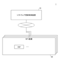
- FIG. 5 is a diagram showing an example of the configuration of a software update control system 1 in an embodiment of the present invention.
- a software update control device 10 is capable of communicating with one or more NFV platforms 20 via a network.
- the NFV platform 20 is a virtualization platform (NFV (Network Functions Virtualization)) on which one or more VNFs (Virtualized Network Functions) can be deployed.
- the NFV platform 20 has a one-to-one correspondence with nodes.
- a node is realized by one or more computers (physical servers) that make up a cluster.
- the NFV platform 20 may be a virtualization platform in an on-premise environment such as OpenStack (registered trademark) or VMware (registered trademark), or it may be a cloud platform such as AWS.
- a VNF is a network function that can be virtualized (an example of a virtual environment that functions as a device that handles packets, such as a virtual router or UPF).
- a VNF may be realized by a virtual machine (VM (Virtual Machine)), or by a container or VRF (Virtual Routing and Forwarding) that virtually separates functions.
- VM Virtual Machine
- VRF Virtual Routing and Forwarding
- the software update control device 10 is one or more computers (e.g., general-purpose servers) that control software updates (hereinafter simply referred to as “updates” or “updates”) for VNFs. This embodiment is particularly effective when there are multiple VNFs to be updated.
- the software update control device 10 can update each VNF using one of multiple types of update procedures (hereinafter referred to as "patterns"), each of which has a known update time and time-series resource consumption.
- patterns multiple types of update procedures
- the pattern assigned to each VNF may be different. In this embodiment, a case in which three patterns are used is described, but two patterns may be used, or four or more patterns may be defined.
- Pattern 1 The first pattern (hereinafter referred to as "Pattern 1") is an update using blue-green deployment as described in FIG. 2. In this embodiment, Pattern 1 is understood as being divided into multiple steps in chronological order.
- FIG. 6 is a diagram for explaining Pattern 1. As shown in Figure 6, Pattern 1 is composed of three steps, STEP 1 to STEP 3, in chronological order.
- STEP 1 is the step in which the new version's active system (Act) and standby system (Sby) are constructed.
- STEP 2 is the step in which the systems are switched (operations are switched from the old version to the new version).
- STEP 3 is the step in which the old version is deleted.
- Pattern 2 The second pattern (hereinafter referred to as "Pattern 2") is composed of the steps shown in Figure 7.
- Figure 7 is a diagram for explaining Pattern 2.
- Pattern 2 is composed of six steps, STEP 1 to STEP 6, in chronological order.
- STEP 1 is a step in which only the new version of the active system (hereinafter referred to as "new Act") is constructed.
- STEP 2 is a step in which operation is switched from the old version of the active system (hereinafter referred to as "old Act") to the new version of Act.
- STEP 3 is a step in which the old Act is deleted.
- STEP 4 is a step in which the new version of the standby system (hereinafter referred to as "new Sby”) is further constructed.
- STEP 5 is a step in which operation is switched from the old version of the standby system (hereinafter referred to as "old Sby") to the new version of Sby.
- STEP 6 is a step in which the old Sby is deleted.
- Pattern 3 The third pattern (hereinafter referred to as "Pattern 3") is composed of the steps shown in Figure 8.
- Figure 8 is a diagram for explaining Pattern 3. As shown in Figure 8, Pattern 3 is composed of five steps, STEP 1 to STEP 5, in chronological order.
- STEP 1 and 2 of pattern 3 are the same as STEP 1 and 2 of pattern 2.
- STEP 3 of pattern 3 is the step where a new Sby is further constructed. That is, in pattern 3, STEP 4 of pattern 2 is executed before STEP 3 of pattern 2.
- STEP 4 of pattern 3 is the step where operation is switched from the old Sby to the new version Sby.
- STEP 5 of pattern 3 is the step where the old Act and new Sby are deleted.
- pattern 3 the number of temporary VNFs (resource usage) is 3 or 4, which is inferior to pattern 2 in terms of resource usage.
- pattern 2 has the risk of not being able to switch back to the old version after STEP 3, pattern 3 does not have such a risk.
- Figures 6 to 8 show the time required and resource usage (number of VFNs (e.g., number of VMs)) for each step (i.e., in chronological order).
- “Act1/Sby” indicates that there is one active system and one standby system.
- the time required and resource usage are parameters that will be used later.
- Information indicating the time required and resource usage for each step of each pattern will be referred to as "pattern information" below.
- the pattern information may be measured in advance by trial updates using each pattern, or may be estimated by any method.
- the software update control device 10 generates an update schedule (a collection of update pipelines (hereinafter simply referred to as "pipelines") for each VNF) for multiple VNFs to be updated based on pattern information, information indicating the deployment destination nodes (NFV platforms 20) for the active and standby systems of multiple VNFs to be updated (hereinafter referred to as “deployment destination information"), and the resource usage or availability (free capacity) of each node.
- the update schedule is referred to as an "update plan.”
- a pipeline for a certain VNF refers to information indicating the pattern to be applied to that VNF and the start timing of each step of that pattern. The start timing of each step of each pipeline is specified as a relative value to the start timing of each step of other pipelines.
- FIG. 9 is a diagram showing an example of the hardware configuration of a software update control device 10 in an embodiment of the present invention.
- the software update control device 10 in FIG. 9 has a drive device 100, an auxiliary storage device 102, a memory device 103, a processor 104, and an interface device 105, which are all interconnected by a bus B.
- the program that realizes the processing in the software update control device 10 is provided by a recording medium 101 such as a CD-ROM.
- a recording medium 101 such as a CD-ROM.
- the program is installed from the recording medium 101 via the drive device 100 into the auxiliary storage device 102.
- the program does not necessarily have to be installed from the recording medium 101, but may be downloaded from another computer via a network.
- the auxiliary storage device 102 stores the installed program as well as necessary files, data, etc.
- the memory device 103 When an instruction to start a program is received, the memory device 103 reads out and stores the program from the auxiliary storage device 102.
- the processor 104 is a CPU or a GPU (Graphics Processing Unit), or a CPU and a GPU, and executes functions related to the software update control device 10 in accordance with the program stored in the memory device 103.
- the interface device 105 is used as an interface for connecting to a network.
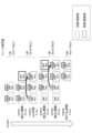
- FIG. 10 is a diagram showing an example of the functional configuration of the software update control system 1 in an embodiment of the present invention.
- Each NFV platform 20 has a resource management unit 21 in addition to one or more VNFs.
- the resource management unit 21 monitors the usage status (in other words, availability) of the resources (CPU, RAM, DISK, NW (communication resources)) of the nodes functioning as the NFV platform 20.
- VNF-1 an example is shown in which the active system (VNF-1 Act) is deployed on the NFV platform 20-1, and the standby system (VNF-1 Sby) is deployed on the NFV platform 20-2.
- VNF-2 an example is shown in which the active system (VNF-2 Act) is deployed on the NFV platform 20-2, and the standby system (VNF-2 Sby) is deployed on the NFV platform 20-3.
- VNF-3 an example is shown in which the active system (VNF-3 Act) is deployed on the NFV platform 20-3, and the standby system (VNF-3 Sby) is deployed on the NFV platform 20-1.
- VNF-4 an example is shown in which the active system (VNF-4 Act) is deployed on NFV platform 20-2, and the standby system (VNF-4 Sby) is deployed on NFV platform 20-1.
- VNF-4 Act active system
- VNF-4 Sby standby system
- each VNF is deployed on a different NFV platform 20 as an active system and a standby system.
- the software update control device 10 has a monitoring unit 11, a generating unit 12, a determining unit 13, and a control unit 14. Each of these units is realized by a process in which one or more programs installed in the software update control device 10 are executed by the processor 104.
- the software update control device 10 also uses a pattern information storage unit 15 and a deployment destination information storage unit 16. Each of these storage units can be realized, for example, by using an auxiliary storage device 102, or a storage device that can be connected to the software update control device 10 via a network, etc.
- the pattern information storage unit 15 stores pattern information for each pattern.
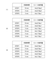
- FIG. 11 is a diagram showing an example of the configuration of pattern information.
- (1) is pattern information corresponding to pattern 1 shown in FIG. 6.
- (2) is pattern information corresponding to pattern 2 shown in FIG. 7.
- (3) is pattern information corresponding to pattern 3 shown in FIG. 8.
- the pattern information is information including the time required for each step constituting the pattern (and thus the time required for the entire pattern) and the resource usage (in chronological order) for each step.
- the pattern information is registered in advance in the pattern information storage unit 15 by being measured in advance by an update trial or estimated by any method.
- the deployment destination information storage unit 16 stores deployment destination information.
- FIG. 12 is a diagram showing an example of the configuration of deployment destination information.
- the deployment destination information is information including an active system deployment destination and a standby system deployment destination for each VNF.
- the active system deployment destination is the NFV platform 20 on which the active system is deployed.
- the standby system deployment destination is the NFV platform 20 on which the standby system is deployed.
- the notation "node N" (N is 1 to 4), which is the identification information of the active system deployment destination and the standby system deployment destination, is the node name of the node corresponding to the NFV platform 20-N.
- the deployment destination information in FIG. 12 corresponds to the deployment destination of each VFN in FIG. 10.
- the monitoring unit 11 obtains information indicating the resource usage (availability) in each NFV platform 20 (each node) (hereinafter referred to as “resource usage information") from the resource management unit 21 of each NFV platform 20.
- FIG. 13 is a diagram showing an example of the configuration of resource usage information.
- information including the respective usage rates of the CPU and RAM for each NFV platform 20 is shown as an example of resource usage information.
- the generation unit 12 generates an update plan by assigning to each of a plurality of VNFs one of a plurality of patterns in which the required time for software updates and the amount of resource usage over time are known, and the start timing of that one of the patterns.
- the determination unit 13 determines whether or not a period will occur in which the upper limit of the resource will be exceeded for each of the one or more nodes (NFV platforms 20) in which each VNF is deployed, based on the time-series resource amount required when performing an update based on the update plan and the resource usage status in the node. If there is a node in which the relevant period occurs, the generation unit 12 generates a new update plan by changing at least one of the type and start timing of the pattern related to the VNF in which the node in which the period occurs is the deployment destination (deployment destination of either the active system or the standby system).
- the control unit 14 controls the execution of updates for each VNF based on the update plan.
- Figure 14 is a flowchart for explaining an example of the processing procedure executed by the software update control device 10.
- step S101 the generation unit 12 generates an update plan to be processed (hereinafter referred to as the "target plan") by assigning the pipeline of pattern 1, which has the shortest required time based on the pattern information (Fig. 11), to all VNFs registered in the deployment destination information (Fig. 12) and assigning simultaneous start timings to the pipelines 1 assigned to each VNF.
- the target plan an update plan to be processed
- FIG. 15 is a diagram showing an example of the first update plan to be generated.
- FIG. 15 shows an update plan in which pipeline execution of pattern 1 is started simultaneously for VNF-1 to 4.
- Such an update plan is set as the first update plan (initial value of the update plan) because pattern 1 is completed the fastest, and therefore it is preferable from the perspective of shortening the update time to update all VNFs in parallel as much as possible with pattern 1.
- pipelines are generated for each VNF, and are not differentiated between active and standby systems. If there are N VNFs, N pipelines are generated, not N x 2. If the active and standby pipelines of a VNF are not common, each step of the update of that VNF will not be consistent between the active and standby systems, making it difficult to execute the update correctly.
- the determination unit 13 calculates information (hereinafter referred to as "required resource information") indicating, in time series, the amount of resources required by each node (NFV platform 20) when executing the target plan (S102).
- the amount of resources required by a certain node at a certain time can be calculated by finding the sum of the resource usage (resource usage of the active system or standby system) at that time of each VNF pipeline that is deployed at that node among the pipelines that make up the target plan.
- the resource usage of a certain pipeline at a certain node and at a certain time can be identified by referring to the value of the system (active system or standby system) deployed at the node among the resource usage of the NFV corresponding to the pipeline in the pattern information ( Figure 11) corresponding to the pattern related to the pipeline.
- the determination unit 13 determines whether or not there is a node (NFV platform 20) in which a period in which the resource upper limit of the node is exceeded (hereinafter referred to as an "excess period") occurs, based on the required resource information of the node and the resource usage information of the node (FIG. 13) (S103).
- the resource usage amount that is the basis of the required resource information is the number of VNFs.
- the resource usage information is the usage rate of the CPU or RAM. Therefore, the determination unit 13 performs such a determination by converting the number of VNFs to the usage rate of the CPU or RAM.
- the usage rate (usage rate) of the CPU or RAM of each VNF may be obtained from the NFV platform 20 where each VNF is deployed, or a conversion table may be generated in advance.
- the required resource information may be compared with the resource usage information (FIG. 13) by converting the resource usage information into the number of VNFs (number of units) based on a predetermined conversion formula or correspondence table, etc.
- the generation unit 12 updates the target plan (generates a new target plan) by modifying the partial update plan (hereinafter referred to as the "change target update plan") for the VNF that has the target node as its deployment destination so that the overage period is eliminated (so that an overage period does not occur) (S105).
- the change of the update plan to be changed is executed, for example, by any one of the following change methods 1 to 3, or a combination of two or more of the change methods 1 to 3.
- (Change Method 1) Changing the start timing of any of the pipelines that make up the update plan to be changed.
- (Change method 2) Change the pattern to be assigned to the VNF that has the target node as its deployment destination.
- (Change method 3) Delaying the start timing of any step of any of the pipelines that make up the update plan to be changed, and including a period during which nothing is executed between the steps of the pipeline (hereinafter referred to as an "interruption period").
- FIG. 18 is a diagram showing an example of applying a combination of change methods 1 and 2 to an update plan.
- FIG. 18 shows an example in which the pipelines of VNF-1 to 4 are changed to pattern 3, and the start timing of the pipelines of VNF-3 and VNF-4 is shifted back. As a result, the maximum amount of resources required by the target node in periods T1 and T2 can be reduced.
- FIG. 19 shows an example of applying change methods 1 and 3 to an update plan.
- the start timing of the VNF-3 pipeline is shifted back, and an example is shown in which interruption periods are inserted between STEPs 1 and 2 and between STEPs 2 and 3 of the pipeline.
- the generation unit 12 may generate multiple or all ways (combinations of patterns and start timing, etc.) for the update plan to be changed within the resource constraints (upper limit) of the target node, and select from among them the change method that will provide the shortest time required for the update plan to be changed (the period from start to finish).
- a constraint may be set that the start timing of the pipeline to be changed matches the boundary of a step of any of the other pipelines constituting the update plan to be changed, or of a pipeline related to another node, in order to make the total number of ways finite.
- an update plan with simultaneous execution of pattern 1 is initially attempted, but if the resource constraints cannot be met, one or more of change methods 1 to 3 are applied to search for an update plan that satisfies the resource constraints and can be executed in a short period of time.
- pattern 2 can reduce the amount of resources required for the update to 1.5 times that before the update, it becomes impossible to switch back to the old version after STEP 3.
- an update in a pipeline of pattern 1 or 3 fails, it is considered that there is a relatively high possibility that other pipelines will fail as well, compared to other cases where this is not the case. Therefore, it is desirable to execute pattern 2, which has a relatively high risk of causing a service interruption (for example, an interruption that exceeds the service interruption time allowed based on the SLA), after there is a proven track record of successful updates.
- a service interruption for example, an interruption that exceeds the service interruption time allowed based on the SLA
- the generation unit 12 may preferentially select the change method in which the start timing of pattern 2 is relatively late among the relevant change methods. By doing so, it is possible to ensure that the pipeline of pattern 2 is executed as late as possible in the update (patterns 1 and 3 are executed before pattern 2).
- risk tolerance a numerical value indicating the tolerable degree of the above-mentioned risks
- One example of risk tolerance is the tolerable service outage time.
- an index indicating the empirical difficulty of reverting e.g., 100 for a VNF that often fails, 10 for a VNF that rarely fails, etc.
- the generation unit 12 may preferentially assign pattern 2 to pipelines related to VNFs with a relatively high (large) risk tolerance.
- VNFs that can tolerate this may be pattern 2.
- the generation unit 12 may assign weights to these three conditions and calculate an evaluation value for each of the multiple generated change methods based on the weights (weighted sum of the weights and the degree to which each condition is satisfied). In this case, the generation unit 12 may select the change method to be adopted based on the evaluation value.
- steps S102 and onwards are repeated. Note that even if the overage period of the target node is resolved in step S105, a new overage period may occur in a node to which the same pipeline as the target node is assigned (a node to which a standby system or working system that is paired with the working system or standby system deployed in the target node is deployed).
- control unit 14 controls the update of each VNF based on the target plan at that time (S106). Specifically, the control unit 14 transmits commands corresponding to each step of each pipeline constituting the target plan to the VNF corresponding to that pipeline at a timing according to the pipeline.
- the generation unit 12 may generate an update plan by using an optimization algorithm such as mathematical optimization (schedule optimization problem).
- the generation unit 12 can generate an update plan by solving a problem of minimizing the required time for the entire update plan as an objective function, with the resource amount based on the resource usage information of each node as a constraint condition.
- step S101 of FIG. 14 the generation unit 12 assigns the pipeline of pattern 2, which has the smallest maximum resource usage based on the pattern information (FIG. 11), to all VNFs registered in the deployment destination information (FIG. 12) as the target plan, and generates an update plan in which simultaneous start timing is assigned to the pipelines 2 assigned to each VNF.
- step S105 the generation unit changes the update plan to be changed so that the overrun period is eliminated (so that the overrun period does not occur) by changing the start timing of one or more of the pipelines that make up the update plan to be changed.
- the pattern is not changed to reduce resource consumption (an update plan using only pattern 2 is searched for).
- a "risk-priority method” may be adopted instead of the time-priority method and the resource-priority method.
- a constraint that pattern 2 should not be used is added to the time-priority method. Therefore, the pattern of each pipeline constituting the update plan generated by the risk-priority method will be pattern 1 or pattern 3.
- Fig. 20 is a diagram for explaining an example of a method for dealing with an update failure.
- Fig. 20 shows an example in which STEP 4 of the pipeline for VNF-1 has failed. The following methods can be considered as methods for dealing with this case.
- the above (1) and (2) may be automatically executed by the control unit 14.
- the judgments in (3) and (4) may be made by the control unit 14 based on a policy set in advance, or an error may be output and left to the operator.
- VNF in which a network function (or network device) is virtualized (made into software) is described as a virtual environment, but this embodiment may also be applied to updates of a virtual environment in which a function (or device) other than a network function is virtualized.
Landscapes
- Engineering & Computer Science (AREA)
- Computer Networks & Wireless Communication (AREA)
- Signal Processing (AREA)
- Hardware Redundancy (AREA)
Abstract
L'invention concerne un dispositif de commande de mise à jour de logiciel générant un calendrier pour une mise à jour de logiciel pour chaque environnement parmi une pluralité d'environnements virtuels par attribution d'un type parmi une pluralité de types de procédures de mise à jour, le temps requis et l'utilisation de ressources dans le temps pour la mise à jour de logiciel étant connus et la synchronisation de début de la procédure de mise à jour. Chaque fois que le programme est généré, le dispositif de commande de mise à jour de logiciel détermine si une période dans laquelle la limite supérieure de la ressource est dépassée se produit dans chacun d'un ou plusieurs nœuds qui sont des destinations de déploiement de l'environnement virtuel sur la base de la quantité de ressources requises dans le temps lors de la réalisation de la mise à jour sur la base du calendrier et de l'état d'utilisation des ressources dans le nœud et génère un nouveau programme en modifiant le type et/ou la temporisation de début de la procédure de mise à jour relative à l'environnement virtuel ayant le nœud dans lequel la période se produit en tant que destination de déploiement, ce qui permet des mises à jour logicielles efficaces tout en permettant d'annuler autant que possible les mises à jour.
Priority Applications (1)
| Application Number | Priority Date | Filing Date | Title |
|---|---|---|---|
| PCT/JP2023/030050 WO2025041237A1 (fr) | 2023-08-21 | 2023-08-21 | Dispositif de commande de mise à jour de logiciel |
Applications Claiming Priority (1)
| Application Number | Priority Date | Filing Date | Title |
|---|---|---|---|
| PCT/JP2023/030050 WO2025041237A1 (fr) | 2023-08-21 | 2023-08-21 | Dispositif de commande de mise à jour de logiciel |
Publications (1)
| Publication Number | Publication Date |
|---|---|
| WO2025041237A1 true WO2025041237A1 (fr) | 2025-02-27 |
Family
ID=94731855
Family Applications (1)
| Application Number | Title | Priority Date | Filing Date |
|---|---|---|---|
| PCT/JP2023/030050 Pending WO2025041237A1 (fr) | 2023-08-21 | 2023-08-21 | Dispositif de commande de mise à jour de logiciel |
Country Status (1)
| Country | Link |
|---|---|
| WO (1) | WO2025041237A1 (fr) |
Citations (3)
| Publication number | Priority date | Publication date | Assignee | Title |
|---|---|---|---|---|
| JP2014067402A (ja) * | 2012-09-04 | 2014-04-17 | Fujitsu Ltd | プログラム、情報処理装置およびスケジュール決定方法 |
| WO2019160030A1 (fr) * | 2018-02-19 | 2019-08-22 | 日本電信電話株式会社 | Système de fourniture de service, procédé d'attribution de ressources et programme d'attribution de ressources |
| EP3734910A1 (fr) * | 2018-01-17 | 2020-11-04 | Huawei Technologies Co., Ltd. | Procédé et dispositif de mise à niveau de pilote |
-
2023
- 2023-08-21 WO PCT/JP2023/030050 patent/WO2025041237A1/fr active Pending
Patent Citations (3)
| Publication number | Priority date | Publication date | Assignee | Title |
|---|---|---|---|---|
| JP2014067402A (ja) * | 2012-09-04 | 2014-04-17 | Fujitsu Ltd | プログラム、情報処理装置およびスケジュール決定方法 |
| EP3734910A1 (fr) * | 2018-01-17 | 2020-11-04 | Huawei Technologies Co., Ltd. | Procédé et dispositif de mise à niveau de pilote |
| WO2019160030A1 (fr) * | 2018-02-19 | 2019-08-22 | 日本電信電話株式会社 | Système de fourniture de service, procédé d'attribution de ressources et programme d'attribution de ressources |
Similar Documents
| Publication | Publication Date | Title |
|---|---|---|
| US11169854B2 (en) | Node eligibility determinations | |
| KR102847916B1 (ko) | 엣지 컴퓨팅 장치를 위한 애플리케이션 배포 방법 및 시스템 | |
| JP5851618B2 (ja) | 複数の企業データセンタおよびクラウドにおける複数の仮想マシンマイグレーションのネットワーク対応調整 | |
| KR101781063B1 (ko) | 동적 자원 관리를 위한 2단계 자원 관리 방법 및 장치 | |
| KR102027604B1 (ko) | 상태 보존형 애플리케이션의 가용성 증가 기법 | |
| CN109525410B (zh) | 分布式存储系统升级管理的方法、装置及分布式存储系统 | |
| EP3234774A1 (fr) | Élasticité pour applications à haute disponibilité | |
| JP6374841B2 (ja) | 仮想マシン配置装置および仮想マシン配置方法 | |
| WO2019160030A1 (fr) | Système de fourniture de service, procédé d'attribution de ressources et programme d'attribution de ressources | |
| JPWO2017179537A1 (ja) | ソフトウェア更新制御装置、ソフトウェア更新制御システム、ソフトウェア更新制御方法、及び、ソフトウェア更新制御プログラムが格納された記録媒体 | |
| Aleyadeh et al. | Optimal container migration/re-instantiation in hybrid computing environments | |
| JP2022192052A5 (fr) | ||
| CN114020405B (zh) | 一种虚拟机调度方法、装置、设备及介质 | |
| CN113032102A (zh) | 资源重调度方法、装置、设备和介质 | |
| CN110134505A (zh) | 一种集群系统的分布式计算方法、系统及介质 | |
| CN113590281A (zh) | 基于动态集中式调度的分布式并行模糊测试方法及系统 | |
| CN104123183B (zh) | 集群作业调度方法和装置 | |
| CN114564305A (zh) | 一种分布式推理的控制方法、装置、设备及可读存储介质 | |
| JP6620609B2 (ja) | 分散処理実行管理プログラム、分散処理実行管理方法および分散処理実行管理装置 | |
| Rista et al. | Improving the network performance of a container-based cloud environment for hadoop systems | |
| EP3655856B1 (fr) | Corrélation de déclencheur destinée à une reconfiguration de système dynamique | |
| WO2025041237A1 (fr) | Dispositif de commande de mise à jour de logiciel | |
| JP2010205208A (ja) | ホストコンピュータ、マルチパスシステム、パス割当方法およびプログラム | |
| JP2009087213A (ja) | 計算機余力算出装置、計算機余力算出方法 | |
| JP2019139533A (ja) | 配置構成装置、および、配置構成方法 |
Legal Events
| Date | Code | Title | Description |
|---|---|---|---|
| 121 | Ep: the epo has been informed by wipo that ep was designated in this application |
Ref document number: 23949698 Country of ref document: EP Kind code of ref document: A1 |
|
| ENP | Entry into the national phase |
Ref document number: 2025541193 Country of ref document: JP Kind code of ref document: A |
|
| WWE | Wipo information: entry into national phase |
Ref document number: 2025541193 Country of ref document: JP |
|
| NENP | Non-entry into the national phase |
Ref country code: DE |