WO2025041237A1 - Software update control device - Google Patents
Software update control device Download PDFInfo
- Publication number
- WO2025041237A1 WO2025041237A1 PCT/JP2023/030050 JP2023030050W WO2025041237A1 WO 2025041237 A1 WO2025041237 A1 WO 2025041237A1 JP 2023030050 W JP2023030050 W JP 2023030050W WO 2025041237 A1 WO2025041237 A1 WO 2025041237A1
- Authority
- WO
- WIPO (PCT)
- Prior art keywords
- update
- pattern
- node
- control device
- period
- Prior art date
- Legal status (The legal status is an assumption and is not a legal conclusion. Google has not performed a legal analysis and makes no representation as to the accuracy of the status listed.)
- Pending
Links
Images


Classifications
-
- H—ELECTRICITY
- H04—ELECTRIC COMMUNICATION TECHNIQUE
- H04L—TRANSMISSION OF DIGITAL INFORMATION, e.g. TELEGRAPHIC COMMUNICATION
- H04L41/00—Arrangements for maintenance, administration or management of data switching networks, e.g. of packet switching networks
- H04L41/08—Configuration management of networks or network elements
- H04L41/0803—Configuration setting
- H04L41/0813—Configuration setting characterised by the conditions triggering a change of settings
- H04L41/082—Configuration setting characterised by the conditions triggering a change of settings the condition being updates or upgrades of network functionality
-
- H—ELECTRICITY
- H04—ELECTRIC COMMUNICATION TECHNIQUE
- H04L—TRANSMISSION OF DIGITAL INFORMATION, e.g. TELEGRAPHIC COMMUNICATION
- H04L41/00—Arrangements for maintenance, administration or management of data switching networks, e.g. of packet switching networks
- H04L41/08—Configuration management of networks or network elements
- H04L41/085—Retrieval of network configuration; Tracking network configuration history
- H04L41/0859—Retrieval of network configuration; Tracking network configuration history by keeping history of different configuration generations or by rolling back to previous configuration versions
-
- H—ELECTRICITY
- H04—ELECTRIC COMMUNICATION TECHNIQUE
- H04L—TRANSMISSION OF DIGITAL INFORMATION, e.g. TELEGRAPHIC COMMUNICATION
- H04L41/00—Arrangements for maintenance, administration or management of data switching networks, e.g. of packet switching networks
- H04L41/08—Configuration management of networks or network elements
- H04L41/0895—Configuration of virtualised networks or elements, e.g. virtualised network function or OpenFlow elements
Definitions
- the present invention relates to a software update control device.
- NFV Network Virtualization technology
- VNFs Virtualized Network Functions
- 5GC User Plane Functions
- rolling update is a technology that performs uninterrupted updates by switching between Active and Standby and updating each of them (Non-Patent Document 1).
- blue-green deployment is a technology that creates (deploys) a new version while maintaining the currently running VNF, and then deletes (undeploys) the old version after the switchover (Non-Patent Document 2).
- Figures 1 and 2 show an example of updating a VNF that functions as a device for routing packets between network devices.
- the present invention was made in consideration of the above points, and aims to make it possible to perform efficient software updates while making reversion as possible as possible.
- the software update control device has a generation unit configured to generate a schedule for the update by assigning to each of a plurality of virtual environments one of a plurality of types of update procedures, the required time for the software update and the amount of resource usage over time being known, and the start timing of the one of the procedures; and a determination unit configured to determine, each time the schedule is generated, whether or not a period of time will occur in which the upper limit of the resource will be exceeded, for each one or more nodes to which the virtual environment is deployed, based on the amount of resources over time required to perform the update based on the schedule and the resource usage status of the node, and the generation unit is configured to generate a new schedule by changing at least one of the type and start timing of the update procedure for the virtual environment to which the virtual environment is deployed, the node in which the period of time occurs.
- FIG. 1 is a diagram for explaining a rolling update.
- FIG. 1 is a diagram to explain blue-green deployment.
- FIG. 1 is a diagram for explaining the problems of blue-green deployment when updating multiple VNFs in parallel.
- FIG. 1 is a diagram for explaining the problems of blue-green deployment when updating multiple VNFs in series.
- 1 is a diagram showing an example of a configuration of a software update control system 1 according to an embodiment of the present invention.
- FIG. 13 is a diagram for explaining pattern 1.
- FIG. 13 is a diagram for explaining pattern 2.
- FIG. 13 is a diagram for explaining pattern 3.
- 1 is a diagram illustrating an example of a hardware configuration of a software update control device 10 according to an embodiment of the present invention.
- FIG. 1 is a diagram illustrating an example of a functional configuration of a software update control system 1 according to an embodiment of the present invention.
- FIG. 11 is a diagram illustrating an example of the configuration of pattern information.
- FIG. 11 is a diagram illustrating an example of the configuration of deployment destination information.
- FIG. 11 is a diagram illustrating an example of the configuration of resource usage information.
- 4 is a flowchart illustrating an example of a processing procedure executed by the software update control device 10.
- FIG. 13 is a diagram illustrating an example of an update plan that is initially generated.
- FIG. 13 is a diagram illustrating an example of converting resource usage information into the number of VNFs.
- FIG. 13 is a diagram illustrating an example of application of change method 1 to an update plan.
- FIG. 11 is a diagram illustrating an example of the configuration of pattern information.
- FIG. 11 is a diagram illustrating an example of the configuration of deployment destination information.
- FIG. 11 is a diagram illustrating an example of the configuration of resource usage
- FIG. 13 is a diagram illustrating an example of application of a combination of change methods 1 and 2 to an update plan.
- FIG. 13 is a diagram illustrating an example of application of change methods 1 and 3 to an update plan.
- FIG. 11 is a diagram for explaining an example of a method for dealing with a failure in updating.
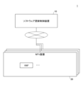
- FIG. 5 is a diagram showing an example of the configuration of a software update control system 1 in an embodiment of the present invention.
- a software update control device 10 is capable of communicating with one or more NFV platforms 20 via a network.
- the NFV platform 20 is a virtualization platform (NFV (Network Functions Virtualization)) on which one or more VNFs (Virtualized Network Functions) can be deployed.
- the NFV platform 20 has a one-to-one correspondence with nodes.
- a node is realized by one or more computers (physical servers) that make up a cluster.
- the NFV platform 20 may be a virtualization platform in an on-premise environment such as OpenStack (registered trademark) or VMware (registered trademark), or it may be a cloud platform such as AWS.
- a VNF is a network function that can be virtualized (an example of a virtual environment that functions as a device that handles packets, such as a virtual router or UPF).
- a VNF may be realized by a virtual machine (VM (Virtual Machine)), or by a container or VRF (Virtual Routing and Forwarding) that virtually separates functions.
- VM Virtual Machine
- VRF Virtual Routing and Forwarding
- the software update control device 10 is one or more computers (e.g., general-purpose servers) that control software updates (hereinafter simply referred to as “updates” or “updates”) for VNFs. This embodiment is particularly effective when there are multiple VNFs to be updated.
- the software update control device 10 can update each VNF using one of multiple types of update procedures (hereinafter referred to as "patterns"), each of which has a known update time and time-series resource consumption.
- patterns multiple types of update procedures
- the pattern assigned to each VNF may be different. In this embodiment, a case in which three patterns are used is described, but two patterns may be used, or four or more patterns may be defined.
- Pattern 1 The first pattern (hereinafter referred to as "Pattern 1") is an update using blue-green deployment as described in FIG. 2. In this embodiment, Pattern 1 is understood as being divided into multiple steps in chronological order.
- FIG. 6 is a diagram for explaining Pattern 1. As shown in Figure 6, Pattern 1 is composed of three steps, STEP 1 to STEP 3, in chronological order.
- STEP 1 is the step in which the new version's active system (Act) and standby system (Sby) are constructed.
- STEP 2 is the step in which the systems are switched (operations are switched from the old version to the new version).
- STEP 3 is the step in which the old version is deleted.
- Pattern 2 The second pattern (hereinafter referred to as "Pattern 2") is composed of the steps shown in Figure 7.
- Figure 7 is a diagram for explaining Pattern 2.
- Pattern 2 is composed of six steps, STEP 1 to STEP 6, in chronological order.
- STEP 1 is a step in which only the new version of the active system (hereinafter referred to as "new Act") is constructed.
- STEP 2 is a step in which operation is switched from the old version of the active system (hereinafter referred to as "old Act") to the new version of Act.
- STEP 3 is a step in which the old Act is deleted.
- STEP 4 is a step in which the new version of the standby system (hereinafter referred to as "new Sby”) is further constructed.
- STEP 5 is a step in which operation is switched from the old version of the standby system (hereinafter referred to as "old Sby") to the new version of Sby.
- STEP 6 is a step in which the old Sby is deleted.
- Pattern 3 The third pattern (hereinafter referred to as "Pattern 3") is composed of the steps shown in Figure 8.
- Figure 8 is a diagram for explaining Pattern 3. As shown in Figure 8, Pattern 3 is composed of five steps, STEP 1 to STEP 5, in chronological order.
- STEP 1 and 2 of pattern 3 are the same as STEP 1 and 2 of pattern 2.
- STEP 3 of pattern 3 is the step where a new Sby is further constructed. That is, in pattern 3, STEP 4 of pattern 2 is executed before STEP 3 of pattern 2.
- STEP 4 of pattern 3 is the step where operation is switched from the old Sby to the new version Sby.
- STEP 5 of pattern 3 is the step where the old Act and new Sby are deleted.
- pattern 3 the number of temporary VNFs (resource usage) is 3 or 4, which is inferior to pattern 2 in terms of resource usage.
- pattern 2 has the risk of not being able to switch back to the old version after STEP 3, pattern 3 does not have such a risk.
- Figures 6 to 8 show the time required and resource usage (number of VFNs (e.g., number of VMs)) for each step (i.e., in chronological order).
- “Act1/Sby” indicates that there is one active system and one standby system.
- the time required and resource usage are parameters that will be used later.
- Information indicating the time required and resource usage for each step of each pattern will be referred to as "pattern information" below.
- the pattern information may be measured in advance by trial updates using each pattern, or may be estimated by any method.
- the software update control device 10 generates an update schedule (a collection of update pipelines (hereinafter simply referred to as "pipelines") for each VNF) for multiple VNFs to be updated based on pattern information, information indicating the deployment destination nodes (NFV platforms 20) for the active and standby systems of multiple VNFs to be updated (hereinafter referred to as “deployment destination information"), and the resource usage or availability (free capacity) of each node.
- the update schedule is referred to as an "update plan.”
- a pipeline for a certain VNF refers to information indicating the pattern to be applied to that VNF and the start timing of each step of that pattern. The start timing of each step of each pipeline is specified as a relative value to the start timing of each step of other pipelines.
- FIG. 9 is a diagram showing an example of the hardware configuration of a software update control device 10 in an embodiment of the present invention.
- the software update control device 10 in FIG. 9 has a drive device 100, an auxiliary storage device 102, a memory device 103, a processor 104, and an interface device 105, which are all interconnected by a bus B.
- the program that realizes the processing in the software update control device 10 is provided by a recording medium 101 such as a CD-ROM.
- a recording medium 101 such as a CD-ROM.
- the program is installed from the recording medium 101 via the drive device 100 into the auxiliary storage device 102.
- the program does not necessarily have to be installed from the recording medium 101, but may be downloaded from another computer via a network.
- the auxiliary storage device 102 stores the installed program as well as necessary files, data, etc.
- the memory device 103 When an instruction to start a program is received, the memory device 103 reads out and stores the program from the auxiliary storage device 102.
- the processor 104 is a CPU or a GPU (Graphics Processing Unit), or a CPU and a GPU, and executes functions related to the software update control device 10 in accordance with the program stored in the memory device 103.
- the interface device 105 is used as an interface for connecting to a network.
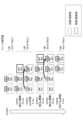
- FIG. 10 is a diagram showing an example of the functional configuration of the software update control system 1 in an embodiment of the present invention.
- Each NFV platform 20 has a resource management unit 21 in addition to one or more VNFs.
- the resource management unit 21 monitors the usage status (in other words, availability) of the resources (CPU, RAM, DISK, NW (communication resources)) of the nodes functioning as the NFV platform 20.
- VNF-1 an example is shown in which the active system (VNF-1 Act) is deployed on the NFV platform 20-1, and the standby system (VNF-1 Sby) is deployed on the NFV platform 20-2.
- VNF-2 an example is shown in which the active system (VNF-2 Act) is deployed on the NFV platform 20-2, and the standby system (VNF-2 Sby) is deployed on the NFV platform 20-3.
- VNF-3 an example is shown in which the active system (VNF-3 Act) is deployed on the NFV platform 20-3, and the standby system (VNF-3 Sby) is deployed on the NFV platform 20-1.
- VNF-4 an example is shown in which the active system (VNF-4 Act) is deployed on NFV platform 20-2, and the standby system (VNF-4 Sby) is deployed on NFV platform 20-1.
- VNF-4 Act active system
- VNF-4 Sby standby system
- each VNF is deployed on a different NFV platform 20 as an active system and a standby system.
- the software update control device 10 has a monitoring unit 11, a generating unit 12, a determining unit 13, and a control unit 14. Each of these units is realized by a process in which one or more programs installed in the software update control device 10 are executed by the processor 104.
- the software update control device 10 also uses a pattern information storage unit 15 and a deployment destination information storage unit 16. Each of these storage units can be realized, for example, by using an auxiliary storage device 102, or a storage device that can be connected to the software update control device 10 via a network, etc.
- the pattern information storage unit 15 stores pattern information for each pattern.
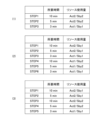
- FIG. 11 is a diagram showing an example of the configuration of pattern information.
- (1) is pattern information corresponding to pattern 1 shown in FIG. 6.
- (2) is pattern information corresponding to pattern 2 shown in FIG. 7.
- (3) is pattern information corresponding to pattern 3 shown in FIG. 8.
- the pattern information is information including the time required for each step constituting the pattern (and thus the time required for the entire pattern) and the resource usage (in chronological order) for each step.
- the pattern information is registered in advance in the pattern information storage unit 15 by being measured in advance by an update trial or estimated by any method.
- the deployment destination information storage unit 16 stores deployment destination information.
- FIG. 12 is a diagram showing an example of the configuration of deployment destination information.
- the deployment destination information is information including an active system deployment destination and a standby system deployment destination for each VNF.
- the active system deployment destination is the NFV platform 20 on which the active system is deployed.
- the standby system deployment destination is the NFV platform 20 on which the standby system is deployed.
- the notation "node N" (N is 1 to 4), which is the identification information of the active system deployment destination and the standby system deployment destination, is the node name of the node corresponding to the NFV platform 20-N.
- the deployment destination information in FIG. 12 corresponds to the deployment destination of each VFN in FIG. 10.
- the monitoring unit 11 obtains information indicating the resource usage (availability) in each NFV platform 20 (each node) (hereinafter referred to as “resource usage information") from the resource management unit 21 of each NFV platform 20.
- FIG. 13 is a diagram showing an example of the configuration of resource usage information.
- information including the respective usage rates of the CPU and RAM for each NFV platform 20 is shown as an example of resource usage information.
- the generation unit 12 generates an update plan by assigning to each of a plurality of VNFs one of a plurality of patterns in which the required time for software updates and the amount of resource usage over time are known, and the start timing of that one of the patterns.
- the determination unit 13 determines whether or not a period will occur in which the upper limit of the resource will be exceeded for each of the one or more nodes (NFV platforms 20) in which each VNF is deployed, based on the time-series resource amount required when performing an update based on the update plan and the resource usage status in the node. If there is a node in which the relevant period occurs, the generation unit 12 generates a new update plan by changing at least one of the type and start timing of the pattern related to the VNF in which the node in which the period occurs is the deployment destination (deployment destination of either the active system or the standby system).
- the control unit 14 controls the execution of updates for each VNF based on the update plan.
- Figure 14 is a flowchart for explaining an example of the processing procedure executed by the software update control device 10.
- step S101 the generation unit 12 generates an update plan to be processed (hereinafter referred to as the "target plan") by assigning the pipeline of pattern 1, which has the shortest required time based on the pattern information (Fig. 11), to all VNFs registered in the deployment destination information (Fig. 12) and assigning simultaneous start timings to the pipelines 1 assigned to each VNF.
- the target plan an update plan to be processed
- FIG. 15 is a diagram showing an example of the first update plan to be generated.
- FIG. 15 shows an update plan in which pipeline execution of pattern 1 is started simultaneously for VNF-1 to 4.
- Such an update plan is set as the first update plan (initial value of the update plan) because pattern 1 is completed the fastest, and therefore it is preferable from the perspective of shortening the update time to update all VNFs in parallel as much as possible with pattern 1.
- pipelines are generated for each VNF, and are not differentiated between active and standby systems. If there are N VNFs, N pipelines are generated, not N x 2. If the active and standby pipelines of a VNF are not common, each step of the update of that VNF will not be consistent between the active and standby systems, making it difficult to execute the update correctly.
- the determination unit 13 calculates information (hereinafter referred to as "required resource information") indicating, in time series, the amount of resources required by each node (NFV platform 20) when executing the target plan (S102).
- the amount of resources required by a certain node at a certain time can be calculated by finding the sum of the resource usage (resource usage of the active system or standby system) at that time of each VNF pipeline that is deployed at that node among the pipelines that make up the target plan.
- the resource usage of a certain pipeline at a certain node and at a certain time can be identified by referring to the value of the system (active system or standby system) deployed at the node among the resource usage of the NFV corresponding to the pipeline in the pattern information ( Figure 11) corresponding to the pattern related to the pipeline.
- the determination unit 13 determines whether or not there is a node (NFV platform 20) in which a period in which the resource upper limit of the node is exceeded (hereinafter referred to as an "excess period") occurs, based on the required resource information of the node and the resource usage information of the node (FIG. 13) (S103).
- the resource usage amount that is the basis of the required resource information is the number of VNFs.
- the resource usage information is the usage rate of the CPU or RAM. Therefore, the determination unit 13 performs such a determination by converting the number of VNFs to the usage rate of the CPU or RAM.
- the usage rate (usage rate) of the CPU or RAM of each VNF may be obtained from the NFV platform 20 where each VNF is deployed, or a conversion table may be generated in advance.
- the required resource information may be compared with the resource usage information (FIG. 13) by converting the resource usage information into the number of VNFs (number of units) based on a predetermined conversion formula or correspondence table, etc.
- the generation unit 12 updates the target plan (generates a new target plan) by modifying the partial update plan (hereinafter referred to as the "change target update plan") for the VNF that has the target node as its deployment destination so that the overage period is eliminated (so that an overage period does not occur) (S105).
- the change of the update plan to be changed is executed, for example, by any one of the following change methods 1 to 3, or a combination of two or more of the change methods 1 to 3.
- (Change Method 1) Changing the start timing of any of the pipelines that make up the update plan to be changed.
- (Change method 2) Change the pattern to be assigned to the VNF that has the target node as its deployment destination.
- (Change method 3) Delaying the start timing of any step of any of the pipelines that make up the update plan to be changed, and including a period during which nothing is executed between the steps of the pipeline (hereinafter referred to as an "interruption period").
- FIG. 18 is a diagram showing an example of applying a combination of change methods 1 and 2 to an update plan.
- FIG. 18 shows an example in which the pipelines of VNF-1 to 4 are changed to pattern 3, and the start timing of the pipelines of VNF-3 and VNF-4 is shifted back. As a result, the maximum amount of resources required by the target node in periods T1 and T2 can be reduced.
- FIG. 19 shows an example of applying change methods 1 and 3 to an update plan.
- the start timing of the VNF-3 pipeline is shifted back, and an example is shown in which interruption periods are inserted between STEPs 1 and 2 and between STEPs 2 and 3 of the pipeline.
- the generation unit 12 may generate multiple or all ways (combinations of patterns and start timing, etc.) for the update plan to be changed within the resource constraints (upper limit) of the target node, and select from among them the change method that will provide the shortest time required for the update plan to be changed (the period from start to finish).
- a constraint may be set that the start timing of the pipeline to be changed matches the boundary of a step of any of the other pipelines constituting the update plan to be changed, or of a pipeline related to another node, in order to make the total number of ways finite.
- an update plan with simultaneous execution of pattern 1 is initially attempted, but if the resource constraints cannot be met, one or more of change methods 1 to 3 are applied to search for an update plan that satisfies the resource constraints and can be executed in a short period of time.
- pattern 2 can reduce the amount of resources required for the update to 1.5 times that before the update, it becomes impossible to switch back to the old version after STEP 3.
- an update in a pipeline of pattern 1 or 3 fails, it is considered that there is a relatively high possibility that other pipelines will fail as well, compared to other cases where this is not the case. Therefore, it is desirable to execute pattern 2, which has a relatively high risk of causing a service interruption (for example, an interruption that exceeds the service interruption time allowed based on the SLA), after there is a proven track record of successful updates.
- a service interruption for example, an interruption that exceeds the service interruption time allowed based on the SLA
- the generation unit 12 may preferentially select the change method in which the start timing of pattern 2 is relatively late among the relevant change methods. By doing so, it is possible to ensure that the pipeline of pattern 2 is executed as late as possible in the update (patterns 1 and 3 are executed before pattern 2).
- risk tolerance a numerical value indicating the tolerable degree of the above-mentioned risks
- One example of risk tolerance is the tolerable service outage time.
- an index indicating the empirical difficulty of reverting e.g., 100 for a VNF that often fails, 10 for a VNF that rarely fails, etc.
- the generation unit 12 may preferentially assign pattern 2 to pipelines related to VNFs with a relatively high (large) risk tolerance.
- VNFs that can tolerate this may be pattern 2.
- the generation unit 12 may assign weights to these three conditions and calculate an evaluation value for each of the multiple generated change methods based on the weights (weighted sum of the weights and the degree to which each condition is satisfied). In this case, the generation unit 12 may select the change method to be adopted based on the evaluation value.
- steps S102 and onwards are repeated. Note that even if the overage period of the target node is resolved in step S105, a new overage period may occur in a node to which the same pipeline as the target node is assigned (a node to which a standby system or working system that is paired with the working system or standby system deployed in the target node is deployed).
- control unit 14 controls the update of each VNF based on the target plan at that time (S106). Specifically, the control unit 14 transmits commands corresponding to each step of each pipeline constituting the target plan to the VNF corresponding to that pipeline at a timing according to the pipeline.
- the generation unit 12 may generate an update plan by using an optimization algorithm such as mathematical optimization (schedule optimization problem).
- the generation unit 12 can generate an update plan by solving a problem of minimizing the required time for the entire update plan as an objective function, with the resource amount based on the resource usage information of each node as a constraint condition.
- step S101 of FIG. 14 the generation unit 12 assigns the pipeline of pattern 2, which has the smallest maximum resource usage based on the pattern information (FIG. 11), to all VNFs registered in the deployment destination information (FIG. 12) as the target plan, and generates an update plan in which simultaneous start timing is assigned to the pipelines 2 assigned to each VNF.
- step S105 the generation unit changes the update plan to be changed so that the overrun period is eliminated (so that the overrun period does not occur) by changing the start timing of one or more of the pipelines that make up the update plan to be changed.
- the pattern is not changed to reduce resource consumption (an update plan using only pattern 2 is searched for).
- a "risk-priority method” may be adopted instead of the time-priority method and the resource-priority method.
- a constraint that pattern 2 should not be used is added to the time-priority method. Therefore, the pattern of each pipeline constituting the update plan generated by the risk-priority method will be pattern 1 or pattern 3.
- Fig. 20 is a diagram for explaining an example of a method for dealing with an update failure.
- Fig. 20 shows an example in which STEP 4 of the pipeline for VNF-1 has failed. The following methods can be considered as methods for dealing with this case.
- the above (1) and (2) may be automatically executed by the control unit 14.
- the judgments in (3) and (4) may be made by the control unit 14 based on a policy set in advance, or an error may be output and left to the operator.
- VNF in which a network function (or network device) is virtualized (made into software) is described as a virtual environment, but this embodiment may also be applied to updates of a virtual environment in which a function (or device) other than a network function is virtualized.
Landscapes
- Engineering & Computer Science (AREA)
- Computer Networks & Wireless Communication (AREA)
- Signal Processing (AREA)
- Hardware Redundancy (AREA)
Abstract
Description
本発明は、ソフトウェア更新制御装置に関する。 The present invention relates to a software update control device.
ネットワーク仮想化技術(NFV(Network Functions Virtualization))は、複数台のネットワーク機能を汎用サーバなどの仮想化基盤上に仮想化して、VNF(Virtualized Network Function)として構築する技術である。ルータやUPF(5GC)などのVNFはActive/Standby構成といった冗長構成によって高可用化される。 Network virtualization technology (NFV (Network Functions Virtualization)) is a technology that virtualizes the network functions of multiple devices on a virtualization platform such as a general-purpose server, and builds them as VNFs (Virtualized Network Functions). VNFs such as routers and UPFs (5GC) are made highly available by using redundant configurations such as an Active/Standby configuration.
したがって、VNFに関するソフトウェアアップデート時においても可能な限り通信断を発生させないこと、また、アップデート後に問題が発生した場合切り戻し(ロールバック)が可能なことが求められる。 Therefore, there is a need to avoid communication interruptions as much as possible when updating software related to VNF, and to be able to roll back if a problem occurs after the update.
Active/Standby構成の従来のソフトウェアアップデート技術として、ローリングアップデート及びブルーグリーン・デプロイメント(「ブルーグリーンアップデート」ともいう。)等がある。 Traditional software update technologies with an Active/Standby configuration include rolling updates and blue-green deployments (also known as "blue-green updates").
ローリングアップデートとは、図1に示されるように、Active-Standbyを切り替えながらそれぞれを更新することで無中断アップデートを実施する技術である(非特許文献1)。 As shown in Figure 1, rolling update is a technology that performs uninterrupted updates by switching between Active and Standby and updating each of them (Non-Patent Document 1).
ブルーグリーン・デプロイメントとは、図2に示されるように、稼働中のVNFは維持したまま新版を新設し(deploy)、切り替えた後に旧版を削除する(undeploy)する技術である(非特許文献2)。 As shown in Figure 2, blue-green deployment is a technology that creates (deploys) a new version while maintaining the currently running VNF, and then deletes (undeploys) the old version after the switchover (Non-Patent Document 2).
なお、図1及び図2では、ネットワーク機器間のパケットをルーティングする機器として機能するVNFのアップデートの例が示されている。 Note that Figures 1 and 2 show an example of updating a VNF that functions as a device for routing packets between network devices.
ローリングアップデートには、使用リソース量を増大させることなくアップデートが可能であるという利点がある反面、アップデート後に問題が発生した場合の切り戻し(新版から旧版へのロールバック)が困難であるという欠点がある。 While rolling updates have the advantage of allowing updates without increasing the amount of resources used, they have the disadvantage that it is difficult to roll back (roll back from the new version to the old version) if a problem occurs after the update.
ブルーグリーン・デプロイメントには、アップデート後に問題が発生した場合に、旧版が残っているため切り戻しが可能であるという利点がある反面、アップデート中の一時的なリソース使用量が増大してしまうという欠点がある。例えば、図3に示されるように、VNF-1~Nの複数の(N個)VNFのアップデートを同時に(並列に)実行する場合、アップデート期間において、N個のVNFのリソース使用量の合計の倍のリソースが必要となってしまう。この場合、空きリソースに余裕がなければアップデートは失敗してしまう。一方、N個のVNFのアップデート期間を単純にずらした場合(つまり、アップデートを直列的に実行した場合)、VNF-1のアップデートが開始されてからVNF-Nのアップデートが終了するまでの期間が長期化してしまうという問題がある。 While blue-green deployment has the advantage that if a problem occurs after an update, it is possible to roll back because the old version remains, it has the disadvantage that the amount of temporary resource usage increases during the update. For example, as shown in Figure 3, when updating multiple (N) VNFs, VNF-1 to N, simultaneously (in parallel), twice the total amount of resources required during the update period will be required as compared to the total amount of resources used by the N VNFs. In this case, if there are not enough free resources, the update will fail. On the other hand, if the update periods for the N VNFs are simply staggered (i.e., when the updates are performed serially), there is a problem in that the period from when the update of VNF-1 starts to when the update of VNF-N finishes will be longer.
本発明は、上記の点に鑑みてなされたものであって、切り戻しをできるだけ可能にしつつ効率的なソフトウェア更新を実行可能とすることを目的とする。 The present invention was made in consideration of the above points, and aims to make it possible to perform efficient software updates while making reversion as possible as possible.
そこで上記課題を解決するため、ソフトウェア更新制御装置は、複数の仮想環境のそれぞれに対して、ソフトウェアの更新に関する所要時間と時系列でのリソース使用量とが既知である複数種類の更新手順のうちのいずれか一つと当該一つの開始タイミングとを割り当てることで前記更新のスケジュールを生成するように構成されている生成部と、前記スケジュールが生成されるたびに、前記仮想環境の配備先である1以上のノードごとに、前記スケジュールに基づいて前記更新を行う場合に必要となる時系列のリソース量と、当該ノードにおけるリソースの使用状況とに基づいて、当該リソースの上限を超過する期間の発生の有無を判定するように構成されている判定部と、を有し、前記生成部は、前記期間が発生するノードを配備先とする前記仮想環境に係る前記更新手順の種類及び開始タイミングの少なくともいずれか一方を変更することで新たな前記スケジュールを生成するように構成されている。 In order to solve the above problem, the software update control device has a generation unit configured to generate a schedule for the update by assigning to each of a plurality of virtual environments one of a plurality of types of update procedures, the required time for the software update and the amount of resource usage over time being known, and the start timing of the one of the procedures; and a determination unit configured to determine, each time the schedule is generated, whether or not a period of time will occur in which the upper limit of the resource will be exceeded, for each one or more nodes to which the virtual environment is deployed, based on the amount of resources over time required to perform the update based on the schedule and the resource usage status of the node, and the generation unit is configured to generate a new schedule by changing at least one of the type and start timing of the update procedure for the virtual environment to which the virtual environment is deployed, the node in which the period of time occurs.
切り戻しをできるだけ可能にしつつ効率的なソフトウェア更新を実行可能とすることができる。 This makes it possible to perform efficient software updates while allowing as much rollback as possible.
以下、図面に基づいて本発明の実施の形態を説明する。図5は、本発明の実施の形態におけるソフトウェア更新制御システム1の構成例を示す図である。図5において、ソフトウェア更新制御装置10は、1以上のNFV基盤20とネットワークを介して通信可能である。
Below, an embodiment of the present invention will be described with reference to the drawings. FIG. 5 is a diagram showing an example of the configuration of a software
NFV基盤20は、1以上のVNF(Virtualized Network Function))を配備可能な仮想化基盤(NFV(Network Functions Virtualization))である。NFV基盤20は、ノードと1対1に対応する。ノードとは、クラスタを構成する1以上のコンピュータ(物理サーバ)によって実現される。なお、NFV基盤20は、OpenStack(登録商標)やVmware(登録商標)などのオンプレミス環境における仮想化基盤であってもよいし、AWSなどのクラウド基盤であてもよい。
The NFV
VNFは、仮想化可能なネットワーク機能(仮想ルータ、UPFなどパケットを扱う機器として機能する仮想環境の一例)である。VNFは、仮想マシン(VM(Virtual Machine))によって実現されてもよいし、コンテナやVRF(Virtual Routing and Forwarding)といった仮想的に機能を分離するものによって実現されてもよい。 A VNF is a network function that can be virtualized (an example of a virtual environment that functions as a device that handles packets, such as a virtual router or UPF). A VNF may be realized by a virtual machine (VM (Virtual Machine)), or by a container or VRF (Virtual Routing and Forwarding) that virtually separates functions.
ソフトウェア更新制御装置10は、VNFについてソフトウェアに関するアップデート(以下、単に「アップデート」又は「更新」という。)を制御する1以上のコンピュータ(例えば、汎用サーバ)である。本実施の形態は、更新対象となるVNFが複数存在する場合において特に有効である。
The software
本実施の形態において、ソフトウェア更新制御装置10は、各VNFについて、それぞれアップデートに関する所要時間と時系列での消費リソースとが既知である複数種類の更新手順(以下、「パターン」という。)のうちのいずれかのパターンによってアップデートを行うことができる。複数のVNFのアップデートを並列的に実行する場合、各VNFに対して割り当てられるパターンは異なってもよい。本実施の形態では、3つのパターンを利用する場合について説明するが、2つのパターンが用いられてもよいし、4つ以上のパターンが定義されてもよい。
In this embodiment, the software
1つ目のパターン(以下、「パターン1」という。)は、図2において説明したブルーグリーン・デプロイメントによるアップデートである。本実施の形態において、パターン1は、複数のステップに時系列に分割されて把握される。
The first pattern (hereinafter referred to as "
図6は、パターン1を説明するための図である。図6に示されるように、パターン1は、時系列順にSTEP1~3の3つのステップによって構成される。
Figure 6 is a diagram for explaining
STEP1は、新版の稼働系(Act)及び待機系(Sby)が構築されるステップである。STEP2は、系切り替え(旧版から新版への運用の切り替え)のステップである。STEP3は、旧版が削除されるステップである。
2つ目のパターン(以下、「パターン2」という。)は、図7に示されるステップによって構成される。図7は、パターン2を説明するための図である。図7に示されるように、パターン2は、時系列順にSTEP1~6の6つのステップによって構成される。
The second pattern (hereinafter referred to as "
STEP1は、新版の稼働系(以下、「新Act」という。)のみが構築されるステップである。STEP2は、旧版の稼働系(以下、「旧Act」という。)から新版Actへ運用が切り替えられるステップである。STEP3は、旧Actが削除されるステップである。STEP4は、新版の待機系(以下、「新Sby」という。)が更に構築されるステップである。STEP5は、旧版の待機系(以下、「旧Sby」という。)から新版Sbyへ運用が切り替えられるステップである。STEP6は、旧Sbyが削除されるステップである。
パターン2では、一時的なVNFの個数(リソース使用量)の最大値が3である。したがって、パターン1よりもリソース使用量を抑制することができる。
In
3つ目のパターン(以下、「パターン3」という。)は、図8に示されるステップによって構成される。図8は、パターン3を説明するための図である。図8に示されるように、パターン3は、時系列順にSTEP1~5の5つのステップによって構成される。
The third pattern (hereinafter referred to as "
パターン3のSTEP1及び2は、パターン2のSTEP1及び2と同じである。パターン3のSTEP3は、新Sbyが更に構築されるステップである。すなわち、パターン3では、パターン2のSTEP3の前にパターン2のSTEP4が実行される。パターン3のSTEP4は、旧Sbyから新版Sbyへ運用が切り替えられるステップである。パターン3のSTEP5は、旧Act及び新Sbyが削除されるステップである。
パターン3では、一時的なVNFの個数(リソース使用量)が3又は4であり、リソース使用量に関してはパターン2よりも劣る。但し、パターン2は、STEP3以降において旧版への切り戻しができなくなるリスクがあるのに対し、パターン3にはそのようなリスクはない。
In
なお、図6~図8には、ステップごとに(つまり、時系列に)所要時間とリソース使用量(VFNの個数(例えば、VMの台数))とが記載されている。リソース使用量の表記において、「Act1/Sby」は、稼働系(Avtive系)が1つであり待機系(Standby系)が1つであることを示す。所要時間及びリソース使用量は、後述において使用されるパラメータである。各パターンのステップごとの所要時間及びリソース使用量を示す情報を、以下「パターン情報」という。パターン情報は、各パターンによるアップデートの試行により予め計測されてもよいし、任意の方法によって推測されてもよい。 Note that Figures 6 to 8 show the time required and resource usage (number of VFNs (e.g., number of VMs)) for each step (i.e., in chronological order). In the notation of resource usage, "Act1/Sby" indicates that there is one active system and one standby system. The time required and resource usage are parameters that will be used later. Information indicating the time required and resource usage for each step of each pattern will be referred to as "pattern information" below. The pattern information may be measured in advance by trial updates using each pattern, or may be estimated by any method.
ソフトウェア更新制御装置10は、パターン情報や、更新対象とされる複数のVNFの稼働系及び待機系それぞれの配備先のノード(NFV基盤20)を示す情報(以下、「配備先情報」という。)、及び各ノードのリソースの使用状況又は空き状況(空き容量)等に基づいて、更新対象とされる複数のVNFについて、更新のスケジュール(VNFごとのアップデートパイプライン(以下、単に「パイプライン」という。)の集合)を生成する。以下、更新のスケジュールを「アップデート計画」という。或るVNFに対するパイプラインは、当該VNFに適用されるパターンと、当該パターンの各ステップの開始タイミングとを示す情報をいう。各パイプラインの各ステップの開始タイミングは、他のパイプラインの各ステップの開始タイミングに対する相対的な値で規定される。
The software
図9は、本発明の実施の形態におけるソフトウェア更新制御装置10のハードウェア構成例を示す図である。図9のソフトウェア更新制御装置10は、それぞれバスBで相互に接続されているドライブ装置100、補助記憶装置102、メモリ装置103、プロセッサ104、及びインタフェース装置105等を有する。
FIG. 9 is a diagram showing an example of the hardware configuration of a software
ソフトウェア更新制御装置10での処理を実現するプログラムは、CD-ROM等の記録媒体101によって提供される。プログラムを記憶した記録媒体101がドライブ装置100にセットされると、プログラムが記録媒体101からドライブ装置100を介して補助記憶装置102にインストールされる。但し、プログラムのインストールは必ずしも記録媒体101より行う必要はなく、ネットワークを介して他のコンピュータよりダウンロードするようにしてもよい。補助記憶装置102は、インストールされたプログラムを格納すると共に、必要なファイルやデータ等を格納する。
The program that realizes the processing in the software
メモリ装置103は、プログラムの起動指示があった場合に、補助記憶装置102からプログラムを読み出して格納する。プロセッサ104は、CPU若しくはGPU(Graphics Processing Unit)、又はCPU及びGPUであり、メモリ装置103に格納されたプログラムに従ってソフトウェア更新制御装置10に係る機能を実行する。インタフェース装置105は、ネットワークに接続するためのインタフェースとして用いられる。
When an instruction to start a program is received, the
図10は、本発明の実施の形態におけるソフトウェア更新制御システム1の機能構成例を示す図である。図10には、NFV基盤20-1~3の3つのNFV基盤20が示されている。各NFV基盤20は、1以上のVNFに加えて、リソース管理部21を有する。リソース管理部21は、NFV基盤20として機能するノードのリソース(CPU、RAM、DISK、NW(通信リソース))の使用状況(換言すれば空き状況)を監視する。
FIG. 10 is a diagram showing an example of the functional configuration of the software
なお、図10には、VNF-1については、稼働系(VNF-1 Act)がNFV基盤20-1に配備され、待機系(VNF-1 Sby)がNFV基盤20-2に配備された例が示されている。また、VNF-2については、稼働系(VNF-2 Act)がNFV基盤20-2に配備され、待機系(VNF-2 Sby)がNFV基盤20-3に配備された例が示されている。また、VNF-3については、稼働系(VNF-3 Act)がNFV基盤20-3に配備され、待機系(VNF-3 Sby)がNFV基盤20-1に配備された例が示されている。また、VNF-4については、稼働系(VNF-4 Act)がNFV基盤20-2に配備され、待機系(VNF-4 Sby)がNFV基盤20-1に配備された例が示されている。このように、各VNFは、単一の物理故障時の影響を抑制するために、稼働系と待機系とで相互に異なるNFV基盤20に配備される。
In addition, in FIG. 10, for VNF-1, an example is shown in which the active system (VNF-1 Act) is deployed on the NFV platform 20-1, and the standby system (VNF-1 Sby) is deployed on the NFV platform 20-2. Also, for VNF-2, an example is shown in which the active system (VNF-2 Act) is deployed on the NFV platform 20-2, and the standby system (VNF-2 Sby) is deployed on the NFV platform 20-3. Also, for VNF-3, an example is shown in which the active system (VNF-3 Act) is deployed on the NFV platform 20-3, and the standby system (VNF-3 Sby) is deployed on the NFV platform 20-1. Also, for VNF-4, an example is shown in which the active system (VNF-4 Act) is deployed on NFV platform 20-2, and the standby system (VNF-4 Sby) is deployed on NFV platform 20-1. In this way, in order to reduce the impact of a single physical failure, each VNF is deployed on a
一方、ソフトウェア更新制御装置10は、監視部11、生成部12、判定部13及び制御部14を有する。これら各部は、ソフトウェア更新制御装置10にインストールされた1以上のプログラムが、プロセッサ104に実行させる処理により実現される。ソフトウェア更新制御装置10は、また、パターン情報記憶部15及び配備先情報記憶部16を利用する。これら各記憶部は、例えば、補助記憶装置102、又はソフトウェア更新制御装置10にネットワークを介して接続可能な記憶装置等を用いて実現可能である。
On the other hand, the software
パターン情報記憶部15には、パターンごとにパターン情報が記憶されている。図11は、パターン情報の構成例を示す図である。図11において、(1)は、図6に示したパターン1に対応するパターン情報である。(2)は、図7に示したパターン2に対応するパターン情報である。(3)、図8に示したパターン3に対応するパターン情報である。パターン情報は、パターンを構成する各ステップの所要時間(ひいては、パターン全体の所要時間)と、ステップごとの(時系列での)リソース使用量とを含む情報である。上記したように、パターン情報は、アップデートの試行により予め計測されたり、任意の方法によって推測されたりすることで、予めパターン情報記憶部15に登録される。
The pattern
配備先情報記憶部16には、配備先情報が記憶されている。図12は、配備先情報の構成例を示す図である。図12に示されるように、配備先情報は、VNFごとに、稼働系配備先及び待機系配備先を含む情報である。稼働系配備先とは、稼働系の配備先となるNFV基盤20である。待機系配備先とは、待機系の配備先となるNFV基盤20である。なお、稼働系配備先及び待機系配備先の識別情報である「ノードN」という表記(Nは1~4)は、NFV基盤20-Nに対応するノードのノード名である。図12の配備先情報は、図10における各VFNの配備先に対応する。
The deployment destination
監視部11は、各NFV基盤20(各ノード)におけるリソースの使用状況(空き状況)を示す情報(以下、「リソース使用情報」という。)を各NFV基盤20のリソース管理部21から取得する。
The
図13は、リソース使用情報の構成例を示す図である。図13には、NFV基盤20ごとに、CPU及びRAMのそれぞれの使用率を含む情報がリソース使用情報の一例として示されている。
FIG. 13 is a diagram showing an example of the configuration of resource usage information. In FIG. 13, information including the respective usage rates of the CPU and RAM for each
生成部12は、複数のVNFのそれぞれに対し、ソフトウェアの更新に関する所要時間と時系列でのリソース使用量とが既知である複数種類のパターンのうちのいずれか一つと当該一つの開始タイミングとを割り当てることでアップデート計画を生成する。
The
判定部13は、アップデート計画が生成されるたびに、各VNFの配備先である1以上のノード(NFV基盤20)ごとに、アップデート計画に基づいて更新を行う場合に必要となる時系列のリソース量と、当該ノードにおけるリソースの使用状況とに基づいて、当該リソースの上限を超過する期間の発生の有無を判定する。該当する期間が発生するノードが有る場合、生成部12は、当該期間が発生するノードを配備先(稼働系及び待機系のいずれかの配備先)とするVNFに係るパターンの種類及び開始タイミングの少なくともいずれか一方を変更することで新たなアップデート計画を生成する。
Each time an update plan is generated, the
制御部14は、アップデート計画に基づいて、各VNFについてアップデートの実行を制御する。
The
以下、ソフトウェア更新制御装置10が実行する処理手順について説明する。図14は、ソフトウェア更新制御装置10が実行する処理手順の一例を説明するためのフローチャートである。
The following describes the processing procedure executed by the software
ステップS101において、生成部12は、処理対象とするアップデート計画(以下、「対象計画」という。)として、配備先情報(図12)に登録されている全てのVNFについて、パターン情報(図11)に基づいて所要時間が最短であるパターン1のパイプラインを割り当て、各VNFに割り当てたパイプライン1に対して同時の開始タイミングを割り当てることでアップデート計画を生成する。
In step S101, the
図15は、最初に生成されるアップデート計画の一例を示す図である。図15には、VNF-1~4についてパターン1のパイプラインの実行が同時に開始されるアップデート計画が示されている。このようなアップデート計画を最初のアップデート計画(アップデート計画の初期値)とするのは、パターン1が最も早く完了するため、可能な限りパターン1で全てのVNFを並列にアップデートすることが、アップデート時間の短縮化の観点において好ましいからである。
FIG. 15 is a diagram showing an example of the first update plan to be generated. FIG. 15 shows an update plan in which pipeline execution of
なお、パイプラインは、VNFごとに生成され、稼働系及び待機系ごとには区別されない。N個のVNFがある場合、生成されるパイプラインはN個であり、N×2個ではない。或るVNFの稼働系及び待機系のパイプラインが共通でないと、当該VNFのアップデートの各ステップが稼働系及び待機系の間で整合しなくなってしまい、アップデートを正常に実行することが困難になってしまうからである。 Note that pipelines are generated for each VNF, and are not differentiated between active and standby systems. If there are N VNFs, N pipelines are generated, not N x 2. If the active and standby pipelines of a VNF are not common, each step of the update of that VNF will not be consistent between the active and standby systems, making it difficult to execute the update correctly.
続いて、判定部13は、対象計画を実行する場合に各ノード(NFV基盤20)が必要とするリソース量を時系列で示す情報(以下、「必要リソース情報」という。)を算出する(S102)。或るノードが或る時点において必要とするリソース量は、対象計画を構成するパイプラインのうち、当該ノードを配備先とする各VNFのパイプラインの当該時点におけるリソース使用量(稼働系又は待機系のリソース使用量)の総和を求めることで算出することができる。或るパイプラインの或るノード及び或る時点におけるリソース使用量は、当該パイプラインに係るパターンに対応するパターン情報(図11)において、当該パイプラインに対応するNFVのリソース使用量のうち当該ノードに配備される系(稼働系又は待機系)の値を参照して特定することができる。
Then, the
続いて、判定部13は、ノード(NFV基盤20)ごとに、当該ノードの必要リソース情報と、当該ノードのリソース使用情報(図13)とに基づいて、当該ノードのリソースの上限を超過する期間(以下、「超過期間」という。)が発生するノードの有無を判定する(S103)。なお、必要リソース情報の元となるリソース使用量は、VNFの個数である。一方、リソース使用情報は、CPUやRAMの使用率である。したがって、判定部13は、VNFの個数をCPUやRAMの使用率に変換することでこのような判定を行う。各VNFのCPUやRAMの使用量(使用率)については、各VNFの配備先のNFV基盤20から取得してもよいし、予め換算表が生成されていてもよい。又は、図16に示されるように、所定の換算式又は対応表等に基づいてリソース使用情報をVNFの個数(台数)に変換することで、必要リソース情報とリソース使用情報(図13)との比較が行われてもよい。
Then, the
超過期間が発生するノード(以下、「対象ノード」という。)が有る場合(S104でNo)、生成部12は、対象ノードを配備先とするVNFに関する部分的なアップデート計画(以下、「変更対象アップデート計画」という。)を、超過期間が解消するように(超過期間が発生しないように)変更することで、対象計画を更新(新たな対象計画を生成)する(S105)。
If there is a node (hereinafter referred to as the "target node") in which an overage period occurs (No in S104), the
変更対象アップデート計画の変更は、例えば、以下の変更方法1~3のいずれか、又は変更方法1~3のうちの2以上の組み合わせによって実行される。
(変更方法1)変更対象アップデート計画を構成するいずれかのパイプラインの開始タイミングを変更すること。
(変更方法2)対象ノードを配備先とするVNFに割り当てるパターンを変更すること。
(変更方法3)変更対象アップデート計画を構成するいずれかのパイプラインのいずれかのステップの開始タイミングを遅延させて、当該パイプラインのステップ間に何も実行しない期間(以下、「中断期間」という。)を含めること。
The change of the update plan to be changed is executed, for example, by any one of the following
(Change Method 1) Changing the start timing of any of the pipelines that make up the update plan to be changed.
(Change method 2) Change the pattern to be assigned to the VNF that has the target node as its deployment destination.
(Change method 3) Delaying the start timing of any step of any of the pipelines that make up the update plan to be changed, and including a period during which nothing is executed between the steps of the pipeline (hereinafter referred to as an "interruption period").
図17は、アップデート計画に対する変更方法1の適用例を示す図である。図17では、VNF-3のパイプラインの開始タイミングが後方にずらされる例が示されている。その結果、期間T1において対象ノードが必要とするリソース量の最大値を低下させることができる。なお、変更対象とするパイプラインの開始タイミングを前方にずらすような変更が行われてもよい。
FIG. 17 is a diagram showing an example of applying
図18は、アップデート計画に対する変更方法1及び2の組み合わせの適用例を示す図である。図18では、VNF-1~4のパイプラインがパターン3に変更され、VNF-3及びVNF-4のパイプラインの開始タイミングが後方にずらされる例が示されている。その結果、期間T1及びT2において対象ノードが必要とするリソース量の最大値を低下させることができる。
FIG. 18 is a diagram showing an example of applying a combination of
図19は、アップデート計画に対する変更方法1及び3の適用例を示す図である。図19では、VNF-3のパイプラインの開始タイミングが後方にずらされ、更に、当該パイプラインのSTTEP1と2の間とSTEP2と3の間のそれぞれに中断期間が挿入される例が示されている。
FIG. 19 shows an example of applying
上記より明らかなように、変更対象アップデート計画の変更方法は複数通りが存在しうる。例えば、生成部12は、変更対象アップデート計画について、対象ノードのリソースの制約(上限)の範囲内において複数通り又は全通りの変更方法(パターン及び開始タイミング等の組み合わせ)を生成し、その中で変更対象アップデート計画の所要時間(開始から終了までの期間)が最短となる変更方法を選択してもよい。全通りの変更方法を生成する場合、全通りを有限にするために、変更対象のパイプラインの開始タイミングが変更対象アップデート計画を構成する他のいずれかのパイプライン、又は他のノードに係るパイプラインのステップの境界に一致するという制約が設けられてもよい。
As is clear from the above, there may be multiple ways to change the update plan to be changed. For example, the
このように、本実施の形態では、当初はパターン1の同時実行でのアップデート計画を試みるが、リソースの制約を満たすことができない場合には、変更方法1~3のいずれか1以上を適用することでリソース制約を満たしつつ、短期間で実行可能なアップデート計画が探索される。
In this way, in this embodiment, an update plan with simultaneous execution of
なお、パターン2は、アップデートに必要なリソース量をアップデート前の1.5倍に抑えられるが、STEP3以降になると旧版への切り戻しができなくなる。また、パターン1や3のパイプラインでのアップデートが失敗した場合には、そうでない場合に比べて他のパイプラインも同様に失敗する可能性が相対的に高いと考えられる。したがって、サービスの中断(例えば、SLAに基づいて許容されるサービス断時間を超える中断)が発生するリスクが相対的に高いパターン2はアップデートの成功実績ができた後に実行されることが望ましい。そうすることで、パターン1や3のパイプラインでのアップデートが失敗した場合に、同様に失敗する可能性があるパターン2のパイプラインも事前に中止することができ、上記のリスクを回避することができる。
In addition, while
そこで、生成部12は、変更対象アップデート計画に対する複数通りの変更方法のうち、パターン2への変更を含む変更方法がある場合には、該当する変更方法の中でパターン2の開始タイミングが相対的に遅い変更方法を優先的に選択するようにしてもよい。そうすることで、パターン2のパイプラインができるだけアップデートの後半に実行されるように(パターン2よりも前にパターン1や3が実行されるように)することができる。
Then, when there is a change method that includes a change to
また、上記のリスクについて許容される度合いを示す数値(以下、「リスク許容度」という。)がVNFごとに設定されるようにしてもよい。リスク許容度の一例として、許容されるサービス断時間が挙げられる。また、切り戻しの経験上の難易度を表した指標(よく失敗することが多いVNFは100、失敗が少ないVNFは10など)がリスク許容度とされてもよい。この場合、生成部12は、複数のパイプラインのいずれかをパターン2に変更したい場合、リスク許容度が相対的に高い(大きい)VNFに係るパイプラインを優先的にパターン2の割り当て対象としてもよい。つまり、切り戻しに失敗すると人間による対処が必要なことが多いため、サービス断時間が長くなる。それを許容できるVNFはパターン2でもよいという考え方である。
Furthermore, a numerical value indicating the tolerable degree of the above-mentioned risks (hereinafter referred to as "risk tolerance") may be set for each VNF. One example of risk tolerance is the tolerable service outage time. Furthermore, an index indicating the empirical difficulty of reverting (e.g., 100 for a VNF that often fails, 10 for a VNF that rarely fails, etc.) may be set as the risk tolerance. In this case, when the
なお、変更対象アップデート計画の所要時間を短縮化すること、パターン2をできるだけ遅らせること、及びリスク許容度が高いVNFに係るパイプラインをパターン2の優先的な割り当て対象とすることのいずれか2以上の条件を組み合わせる場合、生成部12は、これら3つの条件に対して重みを付与し、当該重みに基づく加重和(重みと各条件を満たす度合いとの加重和)によって、生成した複数通りの変更方法のそれぞれについて評価値を算出してもよい。この場合、生成部12は、当該評価値に基づいて採用する変更方法を選択してもよい。
In addition, when two or more of the conditions of shortening the time required for the change target update plan, delaying
ステップS105に続いて、ステップS102以降が繰り返される。なお、ステップS105において対象ノードの超過期間が解消したとしても、対象ノードと同じパイプラインが割り当てられているノード(対象ノードに配備される稼働系又は待機系と対となる待機系又は稼働系が配備されるノード)において、超過期間が新たに発生する可能性が有る。 Following step S105, steps S102 and onwards are repeated. Note that even if the overage period of the target node is resolved in step S105, a new overage period may occur in a node to which the same pipeline as the target node is assigned (a node to which a standby system or working system that is paired with the working system or standby system deployed in the target node is deployed).
ステップS102以降が繰り返される過程において、超過期間が発生するノードが無くなると(S104でYes)、制御部14は、その時点での対象計画に基づき各VNFのアップデートを制御する(S106)。具体的には、制御部14は、対象計画を構成する各パイプラインに従ったタイミングで、当該パイプラインの各ステップに対応する命令を当該パイプラインに対応するVNFに対して送信する。
When there are no more nodes in which an overrun period occurs while steps S102 and after are repeated (Yes in S104), the
なお、生成部12は、図14の処理手順を実行する代わりに、数理最適化(スケジュール最適化問題)といった最適化アルゴリズムを使用することでアップデート計画を生成してもよい。この場合、生成部12は、各ノードのリソース使用情報に基づくリソース量を制約条件とし、アップデート計画全体の所要時間を目的関数として最小化する問題を解くことで、アップデート計画を生成することができる。
In addition, instead of executing the processing procedure of FIG. 14, the
また、上記では、全体の所要時間が最短となる方式(「時間優先方式」)を採用する例について説明したが、例えば、時間に余裕があるがリソース消費(又はアップデートに要する(経済的な)コスト)はなるべく抑制したい場合は「リソース優先方式」に基づいてアップデート計画が生成されてもよい。パターン1~3の中で、リソース使用量の最大値(つまり、コストの最大値)を最も抑制することができるのはパターン2である。したがって、リソース優先方式の場合、図14のステップS101において、生成部12は、対象計画として、配備先情報(図12)に登録されている全てのVNFについて、パターン情報(図11)に基づいてリソース使用量の最大値が最小であるパターン2のパイプラインを割り当て、各VNFに割り当てたパイプライン2に対して同時の開始タイミングを割り当てたアップデート計画を生成する。
In addition, in the above, an example of adopting a method that minimizes the total required time ("time priority method") has been described, but for example, if there is time to spare but it is desired to suppress resource consumption (or the (economic) cost required for the update) as much as possible, an update plan may be generated based on the "resource priority method". Among
また、リソース優先方式の場合、ステップS105において、生成部は、変更対象アップデート計画を構成するいずれか1以上のパイプラインの開始タイミングを変更することによって、超過期間が解消するように(超過期間が発生しないように)変更対象アップデート計画を変更する。つまり、リソース優先方式の場合、リソース消費を抑制するためにパターンの変更は行われない(パターン2のみを用いたアップデート計画が探索される。)。
In addition, in the case of the resource priority method, in step S105, the generation unit changes the update plan to be changed so that the overrun period is eliminated (so that the overrun period does not occur) by changing the start timing of one or more of the pipelines that make up the update plan to be changed. In other words, in the case of the resource priority method, the pattern is not changed to reduce resource consumption (an update plan using
又は、切り戻し失敗のリスクを最小限にすることを目的とする場合、時間優先方式及びリソース優先方式ではなく、「リスク優先方式」が採用されてもよい。リスク優先方式では、時間優先方式に対してパターン2を使用しないという制約が追加されればよい。したがって、リスク優先方式によって生成されるアップデート計画を構成する各パイプラインのパターンは、パターン1又はパターン3となる。
Alternatively, if the objective is to minimize the risk of rollback failure, a "risk-priority method" may be adopted instead of the time-priority method and the resource-priority method. In the risk-priority method, a constraint that
なお、時間優先方式、リソース優先方式及びリスク優先方式のいずれの場合であっても、図14のステップS106において制御部14がアップデート計画に基づいてアップデートの制御を実行中に、いずれかのパイプラインが失敗する可能性が有る。この場合の対処方法について説明する。
Note that in any of the cases of the time-priority method, the resource-priority method, and the risk-priority method, while the
図20は、アップデートの失敗時の対処方法の一例を説明するための図である。図20では、VNF-1に対するパイプラインのSTEP4が失敗した例が示されている。この場合の対処方法として以下が考えられる。
(1)実行済みパイプライン:何もしない。
(2)失敗パイプライン:切り戻す(フェイルバック)。
(3)実行中パイプライン:そのまま継続するか又は切り戻すか(フェイルバックするか)を判断する。
(4)未実行パイプライン:予定通り実行するか又は実行を中止するかを判断する。
Fig. 20 is a diagram for explaining an example of a method for dealing with an update failure. Fig. 20 shows an example in which
(1) Executed pipeline: Do nothing.
(2) Failed Pipeline: Failback.
(3) A running pipeline: Determine whether to continue or to fail back.
(4) Unexecuted pipeline: Determine whether to execute the pipeline as scheduled or to abort the execution.
上記の(1)及び(2)は、制御部14が自動的に実行すればよい。(3)及び(4)における判断は、制御部14が事前に設定されたポリシーに基づいて行ってもよいし、エラーを出力して運用者に委ねてもよい。
The above (1) and (2) may be automatically executed by the
上述したように、本実施の形態によれば、切り戻しをできるだけ可能にしつつ効率的なソフトウェア更新を実行可能とすることができる。例えば、リソースの制約の範囲内において所要時間が短くなる(最短となる)、又は消費リソースが少なくなる(最小となる)アップデート計画を生成することで、効率的なソフトウェア更新を実行可能とすることができる。 As described above, according to this embodiment, it is possible to perform efficient software updates while making reversion possible as much as possible. For example, by generating an update plan that requires less time (shortest possible time) or consumes fewer resources (minimum possible time) within the resource constraints, it is possible to perform efficient software updates.
なお、本実施の形態では、ネットワーク機能(又はネットワーク機器)が仮想化(ソフトウェア化)されたVNFを仮想環境について説明したが、ネットワーク機能以外の機能(又は機器)が仮想化された仮想環境の更新に対して本実施の形態が適用されてもよい。 In this embodiment, the VNF in which a network function (or network device) is virtualized (made into software) is described as a virtual environment, but this embodiment may also be applied to updates of a virtual environment in which a function (or device) other than a network function is virtualized.
以上、本発明の実施の形態について詳述したが、本発明は斯かる特定の実施形態に限定されるものではなく、請求の範囲に記載された本発明の要旨の範囲内において、種々の変形・変更が可能である。 The above describes in detail the embodiments of the present invention, but the present invention is not limited to such specific embodiments, and various modifications and variations are possible within the scope of the gist of the present invention as described in the claims.
1 ソフトウェア更新制御システム
10 ソフトウェア更新制御装置
11 監視部
12 生成部
13 判定部
14 制御部
15 パターン情報記憶部
16 配備先情報記憶部
20 NFV基盤
21 リソース管理部
100 ドライブ装置
101 記録媒体
102 補助記憶装置
103 メモリ装置
104 プロセッサ
105 インタフェース装置
B バス
Claims (4)
前記スケジュールが生成されるたびに、前記仮想環境の配備先である1以上のノードごとに、前記スケジュールに基づいて前記更新を行う場合に必要となる時系列のリソース量と、当該ノードにおけるリソースの使用状況とに基づいて、当該リソースの上限を超過する期間の発生の有無を判定するように構成されている判定部と、
を有し、
前記生成部は、前記期間が発生するノードを配備先とする前記仮想環境に係る前記更新手順の種類及び開始タイミングの少なくともいずれか一方を変更することで新たな前記スケジュールを生成するように構成されている、
ことを特徴とするソフトウェア更新制御装置。 a generating unit configured to generate a schedule of the updates by assigning to each of a plurality of virtual environments one of a plurality of types of update procedures, each of which has a known required time for updating software and a known amount of resource usage over time, and a start timing of the one of the update procedures;
a determination unit configured to determine, each time the schedule is generated, for each one or more nodes to which the virtual environment is deployed, whether or not a period will occur in which the upper limit of the resource will be exceeded, based on a time-series resource amount required when the update is performed based on the schedule and a resource usage status in the node;
having
the generation unit is configured to generate a new schedule by changing at least one of a type and a start timing of the update procedure related to the virtual environment in which the node in which the period occurs is a deployment destination.
A software update control device comprising:
ことを特徴とする請求項1記載のソフトウェア更新制御装置。 the generation unit is configured to select a combination that minimizes a required time for the update in a node in which the period occurs from among a plurality of combinations of the update procedures and the start timings that can eliminate the occurrence of the period.
2. The software update control device according to claim 1,
ことを特徴とする請求項1記載のソフトウェア更新制御装置。 the generation unit is configured to select a combination that minimizes a maximum value of a resource usage amount in a node in which the period occurs from among a plurality of combinations of the update procedure and the start timing that can eliminate the occurrence of the period.
2. The software update control device according to claim 1.
ことを特徴とする請求項2又は3記載のソフトウェア更新制御装置。 The generation unit is configured to select a combination in which the start timing of the update procedure is relatively late, which makes it impossible to switch back, from among a plurality of combinations of the update procedure and the start timing that can eliminate the occurrence of the period.
4. The software update control device according to claim 2 or 3.
Priority Applications (1)
| Application Number | Priority Date | Filing Date | Title |
|---|---|---|---|
| PCT/JP2023/030050 WO2025041237A1 (en) | 2023-08-21 | 2023-08-21 | Software update control device |
Applications Claiming Priority (1)
| Application Number | Priority Date | Filing Date | Title |
|---|---|---|---|
| PCT/JP2023/030050 WO2025041237A1 (en) | 2023-08-21 | 2023-08-21 | Software update control device |
Publications (1)
| Publication Number | Publication Date |
|---|---|
| WO2025041237A1 true WO2025041237A1 (en) | 2025-02-27 |
Family
ID=94731855
Family Applications (1)
| Application Number | Title | Priority Date | Filing Date |
|---|---|---|---|
| PCT/JP2023/030050 Pending WO2025041237A1 (en) | 2023-08-21 | 2023-08-21 | Software update control device |
Country Status (1)
| Country | Link |
|---|---|
| WO (1) | WO2025041237A1 (en) |
Citations (3)
| Publication number | Priority date | Publication date | Assignee | Title |
|---|---|---|---|---|
| JP2014067402A (en) * | 2012-09-04 | 2014-04-17 | Fujitsu Ltd | Program, information processing apparatus, and schedule determination method |
| WO2019160030A1 (en) * | 2018-02-19 | 2019-08-22 | 日本電信電話株式会社 | Service provision system, resource allocation method, and resource allocation program |
| EP3734910A1 (en) * | 2018-01-17 | 2020-11-04 | Huawei Technologies Co., Ltd. | Method and device for upgrading driver |
-
2023
- 2023-08-21 WO PCT/JP2023/030050 patent/WO2025041237A1/en active Pending
Patent Citations (3)
| Publication number | Priority date | Publication date | Assignee | Title |
|---|---|---|---|---|
| JP2014067402A (en) * | 2012-09-04 | 2014-04-17 | Fujitsu Ltd | Program, information processing apparatus, and schedule determination method |
| EP3734910A1 (en) * | 2018-01-17 | 2020-11-04 | Huawei Technologies Co., Ltd. | Method and device for upgrading driver |
| WO2019160030A1 (en) * | 2018-02-19 | 2019-08-22 | 日本電信電話株式会社 | Service provision system, resource allocation method, and resource allocation program |
Similar Documents
| Publication | Publication Date | Title |
|---|---|---|
| US11169854B2 (en) | Node eligibility determinations | |
| KR102847916B1 (en) | Method and system for distributing application for edge computing devices | |
| JP5851618B2 (en) | Network-ready coordination of multiple virtual machine migrations in multiple corporate data centers and clouds | |
| KR101781063B1 (en) | Two-level resource management method and appratus for dynamic resource management | |
| KR102027604B1 (en) | Increasing availability of stateful applications | |
| CN109525410B (en) | Distributed storage system upgrade management method, device and distributed storage system | |
| EP3234774A1 (en) | Elasticity for highly availabile applications | |
| JP6374841B2 (en) | Virtual machine placement apparatus and virtual machine placement method | |
| WO2019160030A1 (en) | Service provision system, resource allocation method, and resource allocation program | |
| JPWO2017179537A1 (en) | SOFTWARE UPDATE CONTROL DEVICE, SOFTWARE UPDATE CONTROL SYSTEM, SOFTWARE UPDATE CONTROL METHOD, AND RECORDING MEDIUM CONTAINING SOFTWARE UPDATE CONTROL PROGRAM | |
| Aleyadeh et al. | Optimal container migration/re-instantiation in hybrid computing environments | |
| JP2022192052A5 (en) | ||
| CN114020405B (en) | Virtual machine scheduling method, device, equipment and medium | |
| CN113032102A (en) | Resource rescheduling method, device, equipment and medium | |
| CN110134505A (en) | A kind of distributed computing method of group system, system and medium | |
| CN113590281A (en) | Distributed parallel fuzzy test method and system based on dynamic centralized scheduling | |
| CN104123183B (en) | Cluster job scheduling method and apparatus | |
| CN114564305A (en) | Control method, device and equipment for distributed inference and readable storage medium | |
| JP6620609B2 (en) | Distributed processing execution management program, distributed processing execution management method, and distributed processing execution management device | |
| Rista et al. | Improving the network performance of a container-based cloud environment for hadoop systems | |
| EP3655856B1 (en) | Trigger correlation for dynamic system reconfiguration | |
| WO2025041237A1 (en) | Software update control device | |
| JP2010205208A (en) | Host computer, multipath system, and method and program for allocating path | |
| JP2009087213A (en) | Computer reserve capacity calculating device and computer reserve capacity calculating method | |
| JP2019139533A (en) | Arrangement configuration device and arrangement configuration method |
Legal Events
| Date | Code | Title | Description |
|---|---|---|---|
| 121 | Ep: the epo has been informed by wipo that ep was designated in this application |
Ref document number: 23949698 Country of ref document: EP Kind code of ref document: A1 |
|
| ENP | Entry into the national phase |
Ref document number: 2025541193 Country of ref document: JP Kind code of ref document: A |
|
| WWE | Wipo information: entry into national phase |
Ref document number: 2025541193 Country of ref document: JP |
|
| NENP | Non-entry into the national phase |
Ref country code: DE |