WO2025041232A1 - Dispositif à cycle de réfrigération et procédé de commande pour dispositif à cycle de réfrigération - Google Patents
Dispositif à cycle de réfrigération et procédé de commande pour dispositif à cycle de réfrigération Download PDFInfo
- Publication number
- WO2025041232A1 WO2025041232A1 PCT/JP2023/030037 JP2023030037W WO2025041232A1 WO 2025041232 A1 WO2025041232 A1 WO 2025041232A1 JP 2023030037 W JP2023030037 W JP 2023030037W WO 2025041232 A1 WO2025041232 A1 WO 2025041232A1
- Authority
- WO
- WIPO (PCT)
- Prior art keywords
- indoor units
- operating
- refrigeration cycle
- units
- control device
- Prior art date
- Legal status (The legal status is an assumption and is not a legal conclusion. Google has not performed a legal analysis and makes no representation as to the accuracy of the status listed.)
- Pending
Links
Images

Classifications
-
- F—MECHANICAL ENGINEERING; LIGHTING; HEATING; WEAPONS; BLASTING
- F24—HEATING; RANGES; VENTILATING
- F24F—AIR-CONDITIONING; AIR-HUMIDIFICATION; VENTILATION; USE OF AIR CURRENTS FOR SCREENING
- F24F11/00—Control or safety arrangements
- F24F11/30—Control or safety arrangements for purposes related to the operation of the system, e.g. for safety or monitoring
- F24F11/48—Control or safety arrangements for purposes related to the operation of the system, e.g. for safety or monitoring prior to normal operation, e.g. pre-heating or pre-cooling
Definitions
- This disclosure relates to a refrigeration cycle device and a method for controlling a refrigeration cycle device.
- Japanese Patent Application Laid-Open Publication No. 10-9689 discloses a refrigeration unit.
- This refrigeration unit has an indoor unit, a heat source unit, and the like.
- This refrigeration unit stores a set temperature and detects the indoor temperature of the indoor unit. Then, when the indoor temperature is higher than the detected temperature, the refrigeration unit performs cooling by the indoor unit (performs thermo ON control). On the other hand, when the indoor temperature is lower than the detected temperature, the refrigeration unit stops cooling by the indoor unit (performs thermo OFF control).
- thermo-ON timing and thermo-OFF timing of the multiple indoor units depend on the indoor temperatures of the multiple indoor units. Therefore, in this refrigeration cycle device, the number of indoor units for which thermo-ON control is executed may become excessively large. In this case, the capacity of the heat source unit may become excessive, and the coefficient of performance (COP) of the refrigeration cycle device may decrease.
- COP coefficient of performance
- the refrigeration cycle device includes a heat source unit, a plurality of indoor units, a control unit, and a plurality of temperature sensors.
- the heat source unit has a compressor that discharges a refrigerant.
- the control unit has a memory that stores the set temperature of each of the plurality of indoor units.
- the plurality of temperature sensors detect the temperature of each room in which each of the plurality of indoor units is installed as a detected temperature.
- the control unit executes a first process of determining the number of indoor units to be operated among the plurality of indoor units based on the detected temperature of each of the plurality of indoor units and a plurality of first difference values between the detected temperature and the corresponding set temperature.
- the control unit executes a second process of determining the indoor units of the operating number from the plurality of indoor units as operating indoor units.
- the control unit then executes a third process of operating the operating indoor units.
- the control method disclosed herein is a method for controlling a refrigeration cycle device.
- the refrigeration cycle device includes a heat source unit, a plurality of indoor units, a control unit, and a plurality of temperature sensors.
- the heat source unit has a compressor that discharges a refrigerant.
- the control unit has a memory that stores the set temperatures of the plurality of indoor units.
- the plurality of temperature sensors detect the temperature of each room in which each of the plurality of indoor units is installed as a detected temperature.
- the control method includes determining the number of indoor units to be operated among the plurality of indoor units based on the detected temperature of each of the plurality of indoor units and a plurality of first difference values between the detected temperature and the corresponding set temperature.
- the control method includes determining the operating number of indoor units from the plurality of indoor units as operating indoor units.
- the control method then includes operating the operating indoor units.
- FIG. 1 is a diagram showing a configuration example of a refrigeration cycle device according to the present disclosure.
- FIG. 2 is a functional block diagram of a control device.
- 4 is a flowchart showing main processing of a control device. 4 is a main flowchart of a number-of-vehicles process according to the first embodiment.
- FIG. 11 is a diagram showing changes in room temperature in each room in a refrigeration cycle device of a comparative example. 4 is a diagram showing changes in room temperature of each room in the refrigeration cycle device of the present embodiment.
- FIG. 1 is a diagram showing changes in ⁇ T of five chambers 51 to 55 in the refrigeration cycle device of the present embodiment.
- FIG. FIG. 13 is a diagram showing the relationship between the number of thermo-ON units and the coefficient of performance. 13 is a main flowchart of the number processing according to the second embodiment.
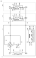
- Fig. 1 is a diagram showing a refrigerant circuit of a refrigeration cycle apparatus 1 according to the first embodiment.
- the refrigeration cycle apparatus 1 includes a heat source unit 2 and N indoor units (N is an integer equal to or greater than 2).
- the N indoor units are also referred to as indoor units 31 to 3N.
- the indoor units 31 to 3N are disposed in chambers 51 to 5N, respectively.
- the refrigeration cycle apparatus 1 includes pipes 89, 90, 92, 94, 96, 97, 98, and 99.
- the refrigeration cycle apparatus 1 is capable of performing cooling operation and heating operation according to settings made by a user or the like.
- the heat source unit 2 includes a compressor 10, an outdoor heat exchanger 40, an outdoor fan 61, a four-way valve 100, and a control device 300.
- the indoor units 31 to 3N include indoor fans 211 to 21N, indoor heat exchangers 201 to 20N, and electronic expansion valves (LEV: Linear Expansion Valves) 111 to 11N, respectively. Note that below, the indoor units 31 to 3N, the indoor fans 211 to 21N, the indoor heat exchangers 201 to 20N, and the electronic expansion valves 111 to 11N are also collectively referred to as the indoor unit 3, the indoor fan 21, the indoor heat exchanger 20, and the electronic expansion valve 11, respectively.
- Tube 92 connects the liquid side refrigerant pipe connection port of the heat source unit 2 to the electronic expansion valves 111-11N.
- Tube 94 connects the liquid side refrigerant pipe connection port of the heat source unit 2 to port P3 of the outdoor heat exchanger 40.
- Tube 96 connects port P4 of the outdoor heat exchanger 40 to port F of the four-way valve 100.
- Tube 98 connects the refrigerant inlet 10a of the compressor 10 to port E of the four-way valve 100.
- Tube 99 is connected between the refrigerant outlet 10b of the compressor 10 and port G of the four-way valve 100.
- the indoor heat exchangers 201-20N are connected to the electronic expansion valves 111-11N, respectively.
- the control device 300 controls the compressor 10, the four-way valve 100, the electronic expansion valve 11, the outdoor fan 61, the indoor fan 21, etc., in response to the outputs of various sensors and operation command signals transmitted from a remote controller or the like.
- the remote controller is operated by a user or the like. Note that in the example of FIG. 1, it is described that temperatures T1 to TN detected by each of the temperature sensors 41 to 4N (temperature sensor 4) are input to the control device 300. Also, in the example of FIG. 1, it is shown that the control device 300 outputs control signals to the compressor 10 and each of the electronic expansion valves 111 to 11N (electronic expansion valve 11).
- the control device 300 includes a CPU (Central Processing Unit) 301, a memory 302, a communication interface 303, etc.
- the memory 302 has, for example, a ROM (Read Only Memory) and a RAM (Random Access Memory). Note that the control of the control device 300 is not limited to processing by software, but can also be processed by dedicated hardware (electronic circuitry).
- the control device 300 controls the operating frequency of the compressor 10 so that the evaporation temperature of the refrigerant (ET: Evaporating Temperature) reaches a predetermined target value.
- the predetermined target value of the evaporation temperature is, for example, 0 degrees.
- the control device 300 controls the operating frequency of the compressor 10 so that the condensation temperature of the refrigerant (CT: Condensation Temperature) reaches a predetermined target value.
- the predetermined target value of the condensation temperature is, for example, 45 degrees.
- the opening of the electronic expansion valve 11 is controlled by a control signal received from the control device 300 to either fully open, perform SH (superheat: degree of superheat, Super Heat) control, SC (subcool: degree of subcooling, Sub Cool) control or close (fully closed).
- SH superheat: degree of superheat, Super Heat
- SC subcool: degree of subcooling, Sub Cool
- the control device 300 adjusts the opening of the electronic expansion valve 11 so that the SH of the refrigerant outlet of the indoor unit 3 reaches a predetermined target value. Also, during heating operation, the control device 300 adjusts the opening of the electronic expansion valve 11 so that the subcooling of the refrigerant outlet of the indoor unit 3 reaches a predetermined target value.
- the predetermined target value is, for example, 3 degrees. Note that sensors for detecting superheat and subcooling are not shown in FIG. 1.
- the temperature sensors 41 to 4N detect the indoor temperatures of rooms 51 to 5N as detected temperatures T1 to TN, respectively.
- the temperature sensors 41 to 4N are shown installed in the indoor units 31 to 3N, respectively. However, the temperature sensors 41 to 4N may be installed in other locations as long as they can detect the indoor temperatures of rooms 51 to 5N.
- the temperature sensors 41 to 4N may be installed outside the indoor units 31 to 3N, respectively.
- the temperature sensors 41 to 4N may also be installed in the remote controllers corresponding to the indoor units 31 to 3N, respectively.
- the fan rotation speed of the indoor fan 21 is driven by a control signal received from the control device 300.
- the fan rotation speed is controlled at a fixed value designed to balance energy saving and noise.
- thermo-ON control The control of allowing at least a portion of the refrigerant compressed and discharged from the compressor 10 to flow into the indoor heat exchanger 20 by opening the electronic expansion valve 11 or the like is also referred to as "first control”.
- the first control is also referred to as “thermo-ON control”.
- the thermo-ON control corresponds to "control for operating the indoor unit” in this disclosure.
- second control the control of not allowing the refrigerant compressed and discharged from the compressor 10 to flow into the indoor heat exchanger 20 by blocking the electronic expansion valve 11 or the like.
- second control The first control is also referred to as "thermo-OFF control”.
- the thermo-OFF control corresponds to "control for stopping operation of the indoor unit” in this disclosure.
- the control device 300 performs thermo-ON and thermo-OFF (first control and second control) for each indoor unit 31-3N by operating the compressor 10 (operating frequency of the compressor 10), opening and closing (adjusting the opening degree) the electronic expansion valves 111-11N, and driving the indoor fans 211-21N.
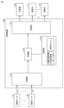
- Fig. 2 is a functional block diagram of the control device 300.
- the control device 300 has a receiving unit 312, a processing unit 314, a storage unit 316, and a transmitting unit 318.
- the receiving unit 312 and the transmitting unit 318 correspond to the communication interface 303 in Fig. 1.
- the processing unit 314 corresponds to the CPU 301.
- the storage unit 316 corresponds to the memory 302.
- temperature sensors 41-4N detect the temperatures of chambers 51-5N as detected temperatures T1-TN, respectively.
- the detected temperatures T1-TN are input to the control device 300, and the receiving unit 312 of the control device 300 receives the detected temperatures T1-TN.
- the detected temperatures T1-TN are output to the processing unit 314.
- the memory unit 316 stores the set temperatures Ts1 to TsN of the indoor units 31 to 3N.
- the set temperatures Ts1 to TsN are set, for example, by a user (such as the administrator of the refrigeration cycle device 1).
- the "previous ⁇ Ta" stored in the memory unit 316 will be described later.
- the processing unit 314 executes unit number processing and determination processing so as to improve the COP of the refrigeration cycle device 1.
- the unit number processing is a process for determining the number of indoor units 3 (operating number) to be operated (thermo-ON).
- the "operating number” is also referred to as the "thermo-ON number”.
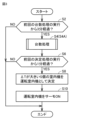
- the processing unit 314 executes the unit number processing for each first cycle. In this embodiment, the first cycle is "3 minutes" as shown in step S2 of FIG. 3 described below.
- the determination process is a process for determining which indoor units will have their thermostats turned ON, based on the number of units with their thermostats turned ON determined by the unit count process.
- the processing unit 314 executes the determination process for each second cycle.
- the second cycle is shorter than the first cycle, and is "1 minute" as shown in step S6 in FIG. 3, which will be described later.
- step S6 the control device 300 determines whether one minute (second cycle) has passed since the previous (most recent) execution of the decision process. If one minute has not passed since the previous (most recent) execution of the decision process (NO in step S6), the process in FIG. 3 ends. If one minute has passed since the previous (most recent) execution of the decision process, the process proceeds to step S8.
- step S8 the control device 300 executes a determination process. Specifically, the control device 300 determines the number S of indoor units with the thermo-ON determined by the number process in step S4. In this embodiment, the control device 300 executes a determination process in which, from the N indoor units 3, the S indoor units with the larger first difference value ⁇ T are determined as the "operating indoor units 3s". The "operating indoor units 3s" are indoor units that will have their thermo-ON. The difference value ⁇ T will be described later.
- step S10 the control device 300 actually operates the operating indoor unit 3s determined in step S8 (executes thermo-ON control for the operating indoor unit). Specifically, in step S10, the control device 300 executes a process to control the operating frequency of the motor of the compressor 10 so that the refrigerant pressure (refrigerant evaporation pressure) of the operating indoor unit 3s becomes a predetermined value.
- the predetermined value will be explained.
- the refrigerant pressure at which the evaporation temperature of the refrigerant corresponds to a first predetermined temperature (for example, 0 degrees) is set as the predetermined value.
- the control device 300 may also predict the heat load based on predetermined parameters (such as outside air temperature), and if the heat load is small, the refrigerant pressure at which the evaporation temperature corresponds to a higher evaporation temperature (for example, 10 degrees) may be set as the predetermined value.
- the refrigerant pressure at which the condensation temperature corresponds to a second predetermined temperature (for example, 45 degrees) is set as the predetermined value.
- the heat load may also be predicted based on the above-mentioned predetermined parameters, and if the heat load is expected to be small, the refrigerant pressure at which the condensation temperature corresponds to a second predetermined temperature (for example, 40 degrees) may be set as the predetermined value.
- a second predetermined temperature for example, 40 degrees
- step S10 the control device 300 adjusts the opening degree of the electronic expansion valve 11s of the operating indoor unit 3s and drives the indoor fan 21s of the operating indoor unit 3s.
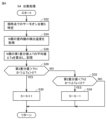
- step S24 the control device 300 acquires the detected temperatures T1 to TN of all N indoor units 31 to 3N from the temperature sensors 41 to 4N.
- step S26 the processing unit 314 calculates multiple first difference values ⁇ Ta1 to ⁇ TaN between the acquired detected temperatures T1 to TN and the set temperatures Ts1 to TsN corresponding to the detected temperatures. Specifically, the processing unit 314 calculates the first difference value ⁇ Ta1 between the detected temperature T1 and the set temperature Ts1, calculates the first difference value ⁇ Ta2 between the detected temperature T2 and the set temperature Ts2, . . . and calculates the first difference value ⁇ TaN between the detected temperature TN and the set temperature TsN.
- the first difference values ⁇ Ta1 to ⁇ TaN are values obtained by subtracting the set temperature from the detected temperature.
- the first difference values ⁇ Ta1 to ⁇ TaN are values obtained by subtracting the detected temperature from the set temperature.
- control device 300 calculates the average value ⁇ Ta of the first difference values ⁇ Ta1 to ⁇ TaN.
- the processing unit 314 calculates the average value ⁇ Ta using the following formula (1).
- step S26 each time the control device 300 calculates the average value ⁇ Ta, the control device 300 stores the average value ⁇ Ta in the memory unit 316 as the previous average value ⁇ Ta (see FIG. 2).
- step S28 the process proceeds to step S28.
- the average value ⁇ Ta is a value indicating the overall deviation (difference) of the N indoor units 3 between the current temperature (detected temperature) and the set temperature. If this average value ⁇ Ta is gradually increasing, it means that the deviation is increasing, so it is preferable to increase the number of thermo-ON units to reduce the deviation. On the other hand, if this average value ⁇ Ta is gradually decreasing, it means that the deviation is decreasing, so it is preferable to decrease the number of thermo-ON units to reduce power consumption.
- step S28 the processing unit 314 calculates a difference value by subtracting the "average value ⁇ Ta calculated previously" from the "average value ⁇ Ta calculated currently". This difference value corresponds to the "second difference value" of the present disclosure.
- a first threshold value Th1 and a second threshold value Th2 that are defined in advance are used.
- the first threshold value Th1 is a positive value
- the second threshold value Th2 is a negative value.
- this second difference value is greater than the first threshold value Th1
- the control device 300 uses the average value ⁇ Ta calculated this time. Specifically, it determines whether the average value ⁇ Ta is positive or negative. In general, it is preferable that the average value ⁇ Ta is closer to "0". Therefore, when the average value ⁇ Ta calculated this time is positive, the number of devices with the thermo ON is increased to bring the average value ⁇ Ta closer to "0". On the other hand, when the average value ⁇ Ta calculated this time is negative, the number of devices with the thermo ON is decreased to reduce power consumption and bring the average value ⁇ Ta closer to "0".
- step S28 the control device 300 determines whether the second difference value is greater than the first threshold value Th1 and ⁇ Ta is positive. If the answer is YES in step S28, that is, if the second difference value is greater than the first threshold value Th1 and ⁇ Ta is positive, the process proceeds to step S30. On the other hand, if the answer is NO in step S28, the process proceeds to step S32.
- step S32 the control device 300 determines whether the second difference value is smaller than the second threshold value Th2 and ⁇ Ta is negative. If step S32 is YES, that is, if the second difference value is smaller than the second threshold value Th2 and ⁇ Ta is negative, the process proceeds to step S34. On the other hand, if step S32 is NO, the process of step S4 ends.
- step S30 the control device 300 determines the number of thermo-ON devices S to be a value calculated by increasing the current number of thermo-ON devices S (the number of thermo-ON devices S identified in step S22) by one.
- step S32 the control device 300 determines the number of thermo-ON devices S to be a value calculated by decreasing the current number of thermo-ON devices S (the number of thermo-ON devices S identified in step S22) by one.
- the process of step S30 corresponds to the "first number process" of this disclosure.
- the process of step S32 corresponds to the "second number process” of this disclosure.
- the control device 300 determines not to change the current number of thermo-ON devices S. This decision corresponds to the "third number process" of this disclosure.
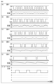
- FIG. 5 is a diagram showing the change in room temperature of each room and the change in the number of thermo-ON units in the comparative refrigeration cycle device.
- FIG. 6 is a diagram showing the change in room temperature of each room and the change in the number of thermo-ON units in the refrigeration cycle device 1 of the present embodiment.
- the capacity of the refrigeration cycle device 1 applied in the simulation will be explained.
- the number of indoor units is "five", and the five indoor units are arranged in the five corresponding rooms. That is, in the example of FIG. 1, indoor units 31 to 35 are arranged in rooms 51 to 55, respectively.
- the capacity of all five indoor units is standardized at 4.5 kW.
- the loads of the five rooms are 2 kW, 2.5 kW, 3 kW, 3.5 kW, and 4 kW, respectively.
- the set temperature of the five indoor units is 27 degrees, and the initial temperature of the five rooms is 27 degrees.
- the control device executes thermo OFF control when the detected temperature (room temperature) reaches a temperature 0.5 degrees lower than the set temperature (i.e., the detected temperature reaches 26.5 degrees). In the refrigeration cycle device of the comparative example, the control device executes thermo ON control when the detected temperature (room temperature) reaches a temperature 0.5 degrees higher than the set temperature (i.e., the detected temperature reaches 27 degrees).
- the first and second cycles in the refrigeration cycle device 1 of this embodiment are 3 minutes and 1 minute, respectively.
- Figures 5(A)-(E) and Figures 6(A)-(E) respectively show the thermo-ON and thermo-OFF states of each indoor unit in rooms 51-55.
- the lower parts of Figures 5(A)-(E) and Figures 6(A)-(E) show the room temperatures in rooms 51-55.
- Figures 5(F) and 6(F) show the change in the number of units with the thermo-ON.
- the horizontal axis of Figures 5(A)-(F) and Figures 6(A)-(F) shows time.
- the number of thermo-ON units varies within a range of 0 to 5 units.
- the range of variation in the number of thermo-ON units is large in the refrigeration cycle device of the comparative example.
- the reason for this variation depends on the indoor temperatures of the multiple indoor units, so the control device executes thermo-ON and thermo-OFF for each indoor unit independently. Therefore, the thermo-ON timing and thermo-OFF timing of each indoor unit are accidental and follow the flow. Therefore, in the refrigeration cycle device of the comparative example, the number of thermo-ON units may be excessive, in which case the instantaneous capacity of the heat source unit may become excessive, and the coefficient of performance of the refrigeration cycle device may decrease.
- the number of thermo-ON units can be changed in increments of three or four units.
- the refrigeration cycle apparatus 1 of this embodiment can reduce the maximum value of the number of thermo-ON units and the range of change in the number of thermo-ON units compared to the refrigeration cycle apparatus of the comparative example. This is because the refrigeration cycle apparatus 1 of this embodiment executes thermo-ON control based on the first difference in all of the multiple indoor units.
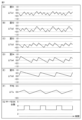
- FIG. 7 is a diagram showing changes in ⁇ T for chambers 51 to 55 in the refrigeration cycle device 1 of this embodiment.
- FIGS. 7(A) to 7(E) show changes in the first difference values ⁇ Ta1 to ⁇ Ta5 for chambers 51 to 55, respectively.
- FIG. 7(F) shows changes in the average value ⁇ Ta of the first difference values.
- FIG. 7(G) shows changes in the number of thermo-ON units, and is a diagram similar to FIG. 6(F).
- the refrigerant circulating flow rate passing through the outdoor heat exchanger 40 of the heat source unit 2 can be reduced, and the heat transfer area of the outdoor heat exchanger 40 of the heat source unit 2 can be increased relative to the refrigerant circulating flow rate. Therefore, when the number of indoor units with the thermostat turned on is small, the coefficient of performance of the refrigeration cycle device 1 can be improved more than when the number of indoor units with the thermostat turned on is large.
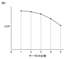
- FIG. 8 is a diagram showing the relationship between the number of thermo-ON units and the coefficient of performance (COP).
- the vertical axis indicates the coefficient of performance
- the horizontal axis indicates the number of thermo-ON units.
- the example of FIG. 8 shows that when the number of indoor units with thermo-ON is small, the coefficient of performance of the refrigeration cycle device 1 is improved more than when the number of indoor units with thermo-ON is large.
- the average COP of the refrigeration cycle device 1 of this embodiment in which the fluctuation range of the number of thermo-ON units is small, is higher than the average COP of the refrigeration cycle device of the comparative example, in which the fluctuation range of the number of thermo-ON units is large.
- the control device 300 executes the first process (the number process in step S4 in FIG. 3).
- the first process is a process for determining the number of indoor units (the number S with thermo-ON) to be operated among the N indoor units 31 to 3N based on a plurality of first difference values ⁇ Ta1 to ⁇ TaN.
- the plurality of first difference values ⁇ Ta1 to ⁇ TaN are difference values between the detected temperatures T1 to TN (indoor temperatures) of the N rooms 51 to 5N and the set temperatures Ts1 to TsN corresponding to the detected temperatures.
- the control device 300 executes the second process (the process in step S8 in FIG.
- the number of indoor units to be operated is determined based on the detected temperatures of each of the multiple indoor units and multiple difference values between the detected temperatures and the corresponding set temperatures, and the determined number of indoor units are operated as operating indoor units. Therefore, for example, the coefficient of performance of the refrigeration cycle device can be improved compared to the refrigeration cycle device of the comparative example described above (see the explanations of Figures 5 to 8).
- the control device 300 executes the first process (the process for the number of units in S4 in FIG. 3) for each first period (step S2 in FIG. 3).
- the control device 300 also executes the second process (the process for step S8 in FIG. 3) for each second period (step S6 in FIG. 3).
- the control device 300 calculates multiple (N) first difference values ⁇ Ta1 to ⁇ TaN by subtracting the set temperatures Ts1 to TsN corresponding to the detected temperatures from the detected temperatures T1 to TN of each of the N indoor units.
- step S28 the control device 300 determines that the number of operating indoor units is too low, and that the average value tends to move away from the desirable value of "0". Therefore, if this is the case, the average value can be brought closer to "0" by increasing the number of operating units in step S30.
- the average value ⁇ Ta is negative (YES in step S32)
- the number of operating units is too high, and that the average value tends to move away from the desirable value of "0”. Therefore, by decreasing the number of operating units in step S34, the power consumption can be reduced and the average value can be brought closer to "0".
- the second process shown in step S8 in FIG. 3 is a process for determining the indoor unit to be operated from among the N indoor units 31 to 3N in order of the indoor unit with the largest first difference value (giving priority to indoor units with large first difference values). Therefore, the refrigeration cycle device 1 can reduce the degree of deviation between the detected temperature and the set temperature by operating an indoor unit with a large degree of deviation.
- the control device 300 controls the operating frequency of the motor of the compressor 10 so that the refrigerant pressure (refrigerant evaporation pressure) of the operating indoor units 3s becomes a predetermined value regardless of the number of indoor units with the thermo-ON.
- the control device 300 can automatically lower the compressor frequency in response to a decrease in the number of indoor units with the thermo-ON.
- the heat transfer area of the outdoor heat exchanger 40 of the heat source unit 2 can be increased relative to the refrigerant circulating flow rate. Therefore, when the number of indoor units with the thermo-ON is small, the coefficient of performance of the refrigeration cycle device 1 can be improved more than when the number of indoor units with the thermo-ON is large.
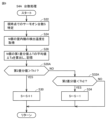
- step S4 in Fig. 3 is replaced by step S4A.
- Fig. 9 is a flowchart of the number processing in step S4A. Comparing Fig. 9 with Fig. 4, steps S28 and S32 in Fig. 4 are replaced by steps S28A and S32A, respectively, in the flowchart in Fig. 9.
- control device 300 does not execute the process of determining whether ⁇ Ta>0 in step S28A, and does not execute the process of determining whether ⁇ Ta ⁇ 0 in step S32A.
- control device 300 may determine whether the second difference value is greater than the first threshold value Th1 in step S28A, and determine whether the second difference value is less than the second threshold value Th2 in step S32A.
- the refrigeration cycle apparatus 1 of the above embodiment uses the average value ⁇ Ta of the first difference values ⁇ Ta1 to ⁇ TaN.
- the refrigeration cycle apparatus 1 may use another value based on the first difference values ⁇ Ta1 to ⁇ TaN instead of the average value ⁇ Ta.
- the other value may be, for example, a total value of the first difference values ⁇ Ta1 to ⁇ TaN.
- the other value may be a multiplication value of the first difference values ⁇ Ta1 to ⁇ TaN.
- the first threshold value Th1 in step S28 of FIG. 4 may be a positive value that is very close to "0". In this case, the process of determining whether the second difference value is greater than the first threshold value Th1 is replaced by a process of determining whether the currently calculated ⁇ Ta is greater than the previously calculated ⁇ Ta. Also, the second threshold value Th2 in step S32 of FIG. 4 may be a negative value that is very close to "0". In this case, the process of determining whether the second difference value is smaller than the second threshold value Th2 is replaced by a process of determining whether the currently calculated ⁇ Ta is smaller than the previously calculated ⁇ Ta.
- 1 refrigeration cycle device 1 refrigeration cycle device, 2 heat source unit, 3 indoor unit, 3s operating indoor unit, 4 temperature sensor, 10 compressor, 10a refrigerant inlet, 10b refrigerant outlet, 11 electronic expansion valve, 20 indoor heat exchanger, 21 indoor fan, 40 outdoor heat exchanger, 61 outdoor fan, 100 four-way valve, 300 control device, 302 memory, 303 communication interface, 312 receiving unit, 314 processing unit, 316 storage unit, 318 transmitting unit.
Landscapes
- Engineering & Computer Science (AREA)
- Chemical & Material Sciences (AREA)
- Combustion & Propulsion (AREA)
- Mechanical Engineering (AREA)
- General Engineering & Computer Science (AREA)
- Air Conditioning Control Device (AREA)
Abstract
L'invention concerne un dispositif à cycle de réfrigération (1) qui comprend une machine source de chaleur (10), une pluralité d'unités intérieures (3), un dispositif de commande (300) et une pluralité de capteurs de température (4). Le dispositif de commande (300) détermine le nombre d'unités intérieures fonctionnelles à mettre en fonctionnement, sur la base d'une pluralité de premières valeurs de différence entre une température détectée de chacune de la pluralité d'unités intérieures (3) et une température de consigne qui correspond à la température détectée. Le dispositif de commande (300) détermine le nombre d'unités intérieures fonctionnelles comme étant les unités intérieures fonctionnelles. Le dispositif de commande (300) met en fonctionnement les unités intérieures fonctionnelles.
Priority Applications (1)
| Application Number | Priority Date | Filing Date | Title |
|---|---|---|---|
| PCT/JP2023/030037 WO2025041232A1 (fr) | 2023-08-21 | 2023-08-21 | Dispositif à cycle de réfrigération et procédé de commande pour dispositif à cycle de réfrigération |
Applications Claiming Priority (1)
| Application Number | Priority Date | Filing Date | Title |
|---|---|---|---|
| PCT/JP2023/030037 WO2025041232A1 (fr) | 2023-08-21 | 2023-08-21 | Dispositif à cycle de réfrigération et procédé de commande pour dispositif à cycle de réfrigération |
Publications (1)
| Publication Number | Publication Date |
|---|---|
| WO2025041232A1 true WO2025041232A1 (fr) | 2025-02-27 |
Family
ID=94731833
Family Applications (1)
| Application Number | Title | Priority Date | Filing Date |
|---|---|---|---|
| PCT/JP2023/030037 Pending WO2025041232A1 (fr) | 2023-08-21 | 2023-08-21 | Dispositif à cycle de réfrigération et procédé de commande pour dispositif à cycle de réfrigération |
Country Status (1)
| Country | Link |
|---|---|
| WO (1) | WO2025041232A1 (fr) |
Citations (2)
| Publication number | Priority date | Publication date | Assignee | Title |
|---|---|---|---|---|
| JPH07318184A (ja) * | 1994-05-23 | 1995-12-08 | Matsushita Electric Ind Co Ltd | 空気調和機 |
| WO2020003447A1 (fr) * | 2018-06-28 | 2020-01-02 | 三菱電機株式会社 | Système de climatisation |
-
2023
- 2023-08-21 WO PCT/JP2023/030037 patent/WO2025041232A1/fr active Pending
Patent Citations (2)
| Publication number | Priority date | Publication date | Assignee | Title |
|---|---|---|---|---|
| JPH07318184A (ja) * | 1994-05-23 | 1995-12-08 | Matsushita Electric Ind Co Ltd | 空気調和機 |
| WO2020003447A1 (fr) * | 2018-06-28 | 2020-01-02 | 三菱電機株式会社 | Système de climatisation |
Similar Documents
| Publication | Publication Date | Title |
|---|---|---|
| CN110671777B (zh) | 一种空调器的控制方法、装置和空调器 | |
| JP6642379B2 (ja) | 空調機 | |
| US10830515B2 (en) | System and method for controlling refrigerant in vapor compression system | |
| US8522568B2 (en) | Refrigeration system | |
| KR101485601B1 (ko) | 공기 조화기 및 그의 제어방법 | |
| US10941951B2 (en) | Systems and methods for temperature and humidity control | |
| JP6609417B2 (ja) | 空気調和機 | |
| JP6910554B2 (ja) | 空気調和装置及び空気調和方法 | |
| CN100516711C (zh) | 多制式空调机的膨胀阀控制方法 | |
| KR20030097179A (ko) | 공기조화기의 압축기 동작방법 | |
| KR102558826B1 (ko) | 공기 조화 시스템 및 제어 방법 | |
| JP2004218879A (ja) | 空気調和機及びその制御方法 | |
| CN103644621A (zh) | 一种中央运算型多联机空调系统及其状态切换控制法 | |
| US20170030621A1 (en) | Low ambient cooling scheme and control | |
| JP6618609B2 (ja) | 冷凍装置 | |
| JP6672619B2 (ja) | 空調システム | |
| JP2001272114A (ja) | 多室形空気調和機の冷媒制御 | |
| WO2025041232A1 (fr) | Dispositif à cycle de réfrigération et procédé de commande pour dispositif à cycle de réfrigération | |
| JP2001241799A (ja) | 多室形空気調和機 | |
| JPH09178247A (ja) | 多室空気調和機の制御装置 | |
| JP2754933B2 (ja) | 多室形空気調和機 | |
| JP6245207B2 (ja) | 空気調和装置 | |
| KR20050034080A (ko) | 실내기 설치 위치에 따른 멀티형 에어컨의 운전 방법 | |
| KR20190094017A (ko) | 멀티형 공기조화기 | |
| WO2024009434A1 (fr) | Dispositif de climatisation et système de climatisation |
Legal Events
| Date | Code | Title | Description |
|---|---|---|---|
| 121 | Ep: the epo has been informed by wipo that ep was designated in this application |
Ref document number: 23949693 Country of ref document: EP Kind code of ref document: A1 |
|
| NENP | Non-entry into the national phase |
Ref country code: DE |