WO2025041232A1 - Refrigeration cycle device and control method for refrigeration cycle device - Google Patents
Refrigeration cycle device and control method for refrigeration cycle device Download PDFInfo
- Publication number
- WO2025041232A1 WO2025041232A1 PCT/JP2023/030037 JP2023030037W WO2025041232A1 WO 2025041232 A1 WO2025041232 A1 WO 2025041232A1 JP 2023030037 W JP2023030037 W JP 2023030037W WO 2025041232 A1 WO2025041232 A1 WO 2025041232A1
- Authority
- WO
- WIPO (PCT)
- Prior art keywords
- indoor units
- operating
- refrigeration cycle
- units
- control device
- Prior art date
- Legal status (The legal status is an assumption and is not a legal conclusion. Google has not performed a legal analysis and makes no representation as to the accuracy of the status listed.)
- Pending
Links
Images

Classifications
-
- F—MECHANICAL ENGINEERING; LIGHTING; HEATING; WEAPONS; BLASTING
- F24—HEATING; RANGES; VENTILATING
- F24F—AIR-CONDITIONING; AIR-HUMIDIFICATION; VENTILATION; USE OF AIR CURRENTS FOR SCREENING
- F24F11/00—Control or safety arrangements
- F24F11/30—Control or safety arrangements for purposes related to the operation of the system, e.g. for safety or monitoring
- F24F11/48—Control or safety arrangements for purposes related to the operation of the system, e.g. for safety or monitoring prior to normal operation, e.g. pre-heating or pre-cooling
Definitions
- This disclosure relates to a refrigeration cycle device and a method for controlling a refrigeration cycle device.
- Japanese Patent Application Laid-Open Publication No. 10-9689 discloses a refrigeration unit.
- This refrigeration unit has an indoor unit, a heat source unit, and the like.
- This refrigeration unit stores a set temperature and detects the indoor temperature of the indoor unit. Then, when the indoor temperature is higher than the detected temperature, the refrigeration unit performs cooling by the indoor unit (performs thermo ON control). On the other hand, when the indoor temperature is lower than the detected temperature, the refrigeration unit stops cooling by the indoor unit (performs thermo OFF control).
- thermo-ON timing and thermo-OFF timing of the multiple indoor units depend on the indoor temperatures of the multiple indoor units. Therefore, in this refrigeration cycle device, the number of indoor units for which thermo-ON control is executed may become excessively large. In this case, the capacity of the heat source unit may become excessive, and the coefficient of performance (COP) of the refrigeration cycle device may decrease.
- COP coefficient of performance
- the refrigeration cycle device includes a heat source unit, a plurality of indoor units, a control unit, and a plurality of temperature sensors.
- the heat source unit has a compressor that discharges a refrigerant.
- the control unit has a memory that stores the set temperature of each of the plurality of indoor units.
- the plurality of temperature sensors detect the temperature of each room in which each of the plurality of indoor units is installed as a detected temperature.
- the control unit executes a first process of determining the number of indoor units to be operated among the plurality of indoor units based on the detected temperature of each of the plurality of indoor units and a plurality of first difference values between the detected temperature and the corresponding set temperature.
- the control unit executes a second process of determining the indoor units of the operating number from the plurality of indoor units as operating indoor units.
- the control unit then executes a third process of operating the operating indoor units.
- the control method disclosed herein is a method for controlling a refrigeration cycle device.
- the refrigeration cycle device includes a heat source unit, a plurality of indoor units, a control unit, and a plurality of temperature sensors.
- the heat source unit has a compressor that discharges a refrigerant.
- the control unit has a memory that stores the set temperatures of the plurality of indoor units.
- the plurality of temperature sensors detect the temperature of each room in which each of the plurality of indoor units is installed as a detected temperature.
- the control method includes determining the number of indoor units to be operated among the plurality of indoor units based on the detected temperature of each of the plurality of indoor units and a plurality of first difference values between the detected temperature and the corresponding set temperature.
- the control method includes determining the operating number of indoor units from the plurality of indoor units as operating indoor units.
- the control method then includes operating the operating indoor units.
- FIG. 1 is a diagram showing a configuration example of a refrigeration cycle device according to the present disclosure.
- FIG. 2 is a functional block diagram of a control device.
- 4 is a flowchart showing main processing of a control device. 4 is a main flowchart of a number-of-vehicles process according to the first embodiment.
- FIG. 11 is a diagram showing changes in room temperature in each room in a refrigeration cycle device of a comparative example. 4 is a diagram showing changes in room temperature of each room in the refrigeration cycle device of the present embodiment.
- FIG. 1 is a diagram showing changes in ⁇ T of five chambers 51 to 55 in the refrigeration cycle device of the present embodiment.
- FIG. FIG. 13 is a diagram showing the relationship between the number of thermo-ON units and the coefficient of performance. 13 is a main flowchart of the number processing according to the second embodiment.
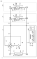
- Fig. 1 is a diagram showing a refrigerant circuit of a refrigeration cycle apparatus 1 according to the first embodiment.
- the refrigeration cycle apparatus 1 includes a heat source unit 2 and N indoor units (N is an integer equal to or greater than 2).
- the N indoor units are also referred to as indoor units 31 to 3N.
- the indoor units 31 to 3N are disposed in chambers 51 to 5N, respectively.
- the refrigeration cycle apparatus 1 includes pipes 89, 90, 92, 94, 96, 97, 98, and 99.
- the refrigeration cycle apparatus 1 is capable of performing cooling operation and heating operation according to settings made by a user or the like.
- the heat source unit 2 includes a compressor 10, an outdoor heat exchanger 40, an outdoor fan 61, a four-way valve 100, and a control device 300.
- the indoor units 31 to 3N include indoor fans 211 to 21N, indoor heat exchangers 201 to 20N, and electronic expansion valves (LEV: Linear Expansion Valves) 111 to 11N, respectively. Note that below, the indoor units 31 to 3N, the indoor fans 211 to 21N, the indoor heat exchangers 201 to 20N, and the electronic expansion valves 111 to 11N are also collectively referred to as the indoor unit 3, the indoor fan 21, the indoor heat exchanger 20, and the electronic expansion valve 11, respectively.
- Tube 92 connects the liquid side refrigerant pipe connection port of the heat source unit 2 to the electronic expansion valves 111-11N.
- Tube 94 connects the liquid side refrigerant pipe connection port of the heat source unit 2 to port P3 of the outdoor heat exchanger 40.
- Tube 96 connects port P4 of the outdoor heat exchanger 40 to port F of the four-way valve 100.
- Tube 98 connects the refrigerant inlet 10a of the compressor 10 to port E of the four-way valve 100.
- Tube 99 is connected between the refrigerant outlet 10b of the compressor 10 and port G of the four-way valve 100.
- the indoor heat exchangers 201-20N are connected to the electronic expansion valves 111-11N, respectively.
- the control device 300 controls the compressor 10, the four-way valve 100, the electronic expansion valve 11, the outdoor fan 61, the indoor fan 21, etc., in response to the outputs of various sensors and operation command signals transmitted from a remote controller or the like.
- the remote controller is operated by a user or the like. Note that in the example of FIG. 1, it is described that temperatures T1 to TN detected by each of the temperature sensors 41 to 4N (temperature sensor 4) are input to the control device 300. Also, in the example of FIG. 1, it is shown that the control device 300 outputs control signals to the compressor 10 and each of the electronic expansion valves 111 to 11N (electronic expansion valve 11).
- the control device 300 includes a CPU (Central Processing Unit) 301, a memory 302, a communication interface 303, etc.
- the memory 302 has, for example, a ROM (Read Only Memory) and a RAM (Random Access Memory). Note that the control of the control device 300 is not limited to processing by software, but can also be processed by dedicated hardware (electronic circuitry).
- the control device 300 controls the operating frequency of the compressor 10 so that the evaporation temperature of the refrigerant (ET: Evaporating Temperature) reaches a predetermined target value.
- the predetermined target value of the evaporation temperature is, for example, 0 degrees.
- the control device 300 controls the operating frequency of the compressor 10 so that the condensation temperature of the refrigerant (CT: Condensation Temperature) reaches a predetermined target value.
- the predetermined target value of the condensation temperature is, for example, 45 degrees.
- the opening of the electronic expansion valve 11 is controlled by a control signal received from the control device 300 to either fully open, perform SH (superheat: degree of superheat, Super Heat) control, SC (subcool: degree of subcooling, Sub Cool) control or close (fully closed).
- SH superheat: degree of superheat, Super Heat
- SC subcool: degree of subcooling, Sub Cool
- the control device 300 adjusts the opening of the electronic expansion valve 11 so that the SH of the refrigerant outlet of the indoor unit 3 reaches a predetermined target value. Also, during heating operation, the control device 300 adjusts the opening of the electronic expansion valve 11 so that the subcooling of the refrigerant outlet of the indoor unit 3 reaches a predetermined target value.
- the predetermined target value is, for example, 3 degrees. Note that sensors for detecting superheat and subcooling are not shown in FIG. 1.
- the temperature sensors 41 to 4N detect the indoor temperatures of rooms 51 to 5N as detected temperatures T1 to TN, respectively.
- the temperature sensors 41 to 4N are shown installed in the indoor units 31 to 3N, respectively. However, the temperature sensors 41 to 4N may be installed in other locations as long as they can detect the indoor temperatures of rooms 51 to 5N.
- the temperature sensors 41 to 4N may be installed outside the indoor units 31 to 3N, respectively.
- the temperature sensors 41 to 4N may also be installed in the remote controllers corresponding to the indoor units 31 to 3N, respectively.
- the fan rotation speed of the indoor fan 21 is driven by a control signal received from the control device 300.
- the fan rotation speed is controlled at a fixed value designed to balance energy saving and noise.
- thermo-ON control The control of allowing at least a portion of the refrigerant compressed and discharged from the compressor 10 to flow into the indoor heat exchanger 20 by opening the electronic expansion valve 11 or the like is also referred to as "first control”.
- the first control is also referred to as “thermo-ON control”.
- the thermo-ON control corresponds to "control for operating the indoor unit” in this disclosure.
- second control the control of not allowing the refrigerant compressed and discharged from the compressor 10 to flow into the indoor heat exchanger 20 by blocking the electronic expansion valve 11 or the like.
- second control The first control is also referred to as "thermo-OFF control”.
- the thermo-OFF control corresponds to "control for stopping operation of the indoor unit” in this disclosure.
- the control device 300 performs thermo-ON and thermo-OFF (first control and second control) for each indoor unit 31-3N by operating the compressor 10 (operating frequency of the compressor 10), opening and closing (adjusting the opening degree) the electronic expansion valves 111-11N, and driving the indoor fans 211-21N.
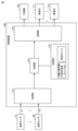
- Fig. 2 is a functional block diagram of the control device 300.
- the control device 300 has a receiving unit 312, a processing unit 314, a storage unit 316, and a transmitting unit 318.
- the receiving unit 312 and the transmitting unit 318 correspond to the communication interface 303 in Fig. 1.
- the processing unit 314 corresponds to the CPU 301.
- the storage unit 316 corresponds to the memory 302.
- temperature sensors 41-4N detect the temperatures of chambers 51-5N as detected temperatures T1-TN, respectively.
- the detected temperatures T1-TN are input to the control device 300, and the receiving unit 312 of the control device 300 receives the detected temperatures T1-TN.
- the detected temperatures T1-TN are output to the processing unit 314.
- the memory unit 316 stores the set temperatures Ts1 to TsN of the indoor units 31 to 3N.
- the set temperatures Ts1 to TsN are set, for example, by a user (such as the administrator of the refrigeration cycle device 1).
- the "previous ⁇ Ta" stored in the memory unit 316 will be described later.
- the processing unit 314 executes unit number processing and determination processing so as to improve the COP of the refrigeration cycle device 1.
- the unit number processing is a process for determining the number of indoor units 3 (operating number) to be operated (thermo-ON).
- the "operating number” is also referred to as the "thermo-ON number”.
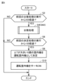
- the processing unit 314 executes the unit number processing for each first cycle. In this embodiment, the first cycle is "3 minutes" as shown in step S2 of FIG. 3 described below.
- the determination process is a process for determining which indoor units will have their thermostats turned ON, based on the number of units with their thermostats turned ON determined by the unit count process.
- the processing unit 314 executes the determination process for each second cycle.
- the second cycle is shorter than the first cycle, and is "1 minute" as shown in step S6 in FIG. 3, which will be described later.
- step S6 the control device 300 determines whether one minute (second cycle) has passed since the previous (most recent) execution of the decision process. If one minute has not passed since the previous (most recent) execution of the decision process (NO in step S6), the process in FIG. 3 ends. If one minute has passed since the previous (most recent) execution of the decision process, the process proceeds to step S8.
- step S8 the control device 300 executes a determination process. Specifically, the control device 300 determines the number S of indoor units with the thermo-ON determined by the number process in step S4. In this embodiment, the control device 300 executes a determination process in which, from the N indoor units 3, the S indoor units with the larger first difference value ⁇ T are determined as the "operating indoor units 3s". The "operating indoor units 3s" are indoor units that will have their thermo-ON. The difference value ⁇ T will be described later.
- step S10 the control device 300 actually operates the operating indoor unit 3s determined in step S8 (executes thermo-ON control for the operating indoor unit). Specifically, in step S10, the control device 300 executes a process to control the operating frequency of the motor of the compressor 10 so that the refrigerant pressure (refrigerant evaporation pressure) of the operating indoor unit 3s becomes a predetermined value.
- the predetermined value will be explained.
- the refrigerant pressure at which the evaporation temperature of the refrigerant corresponds to a first predetermined temperature (for example, 0 degrees) is set as the predetermined value.
- the control device 300 may also predict the heat load based on predetermined parameters (such as outside air temperature), and if the heat load is small, the refrigerant pressure at which the evaporation temperature corresponds to a higher evaporation temperature (for example, 10 degrees) may be set as the predetermined value.
- the refrigerant pressure at which the condensation temperature corresponds to a second predetermined temperature (for example, 45 degrees) is set as the predetermined value.
- the heat load may also be predicted based on the above-mentioned predetermined parameters, and if the heat load is expected to be small, the refrigerant pressure at which the condensation temperature corresponds to a second predetermined temperature (for example, 40 degrees) may be set as the predetermined value.
- a second predetermined temperature for example, 40 degrees
- step S10 the control device 300 adjusts the opening degree of the electronic expansion valve 11s of the operating indoor unit 3s and drives the indoor fan 21s of the operating indoor unit 3s.
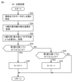
- step S24 the control device 300 acquires the detected temperatures T1 to TN of all N indoor units 31 to 3N from the temperature sensors 41 to 4N.
- step S26 the processing unit 314 calculates multiple first difference values ⁇ Ta1 to ⁇ TaN between the acquired detected temperatures T1 to TN and the set temperatures Ts1 to TsN corresponding to the detected temperatures. Specifically, the processing unit 314 calculates the first difference value ⁇ Ta1 between the detected temperature T1 and the set temperature Ts1, calculates the first difference value ⁇ Ta2 between the detected temperature T2 and the set temperature Ts2, . . . and calculates the first difference value ⁇ TaN between the detected temperature TN and the set temperature TsN.
- the first difference values ⁇ Ta1 to ⁇ TaN are values obtained by subtracting the set temperature from the detected temperature.
- the first difference values ⁇ Ta1 to ⁇ TaN are values obtained by subtracting the detected temperature from the set temperature.
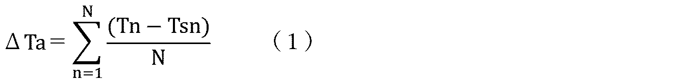
- control device 300 calculates the average value ⁇ Ta of the first difference values ⁇ Ta1 to ⁇ TaN.
- the processing unit 314 calculates the average value ⁇ Ta using the following formula (1).
- step S26 each time the control device 300 calculates the average value ⁇ Ta, the control device 300 stores the average value ⁇ Ta in the memory unit 316 as the previous average value ⁇ Ta (see FIG. 2).
- step S28 the process proceeds to step S28.
- the average value ⁇ Ta is a value indicating the overall deviation (difference) of the N indoor units 3 between the current temperature (detected temperature) and the set temperature. If this average value ⁇ Ta is gradually increasing, it means that the deviation is increasing, so it is preferable to increase the number of thermo-ON units to reduce the deviation. On the other hand, if this average value ⁇ Ta is gradually decreasing, it means that the deviation is decreasing, so it is preferable to decrease the number of thermo-ON units to reduce power consumption.
- step S28 the processing unit 314 calculates a difference value by subtracting the "average value ⁇ Ta calculated previously" from the "average value ⁇ Ta calculated currently". This difference value corresponds to the "second difference value" of the present disclosure.
- a first threshold value Th1 and a second threshold value Th2 that are defined in advance are used.
- the first threshold value Th1 is a positive value
- the second threshold value Th2 is a negative value.
- this second difference value is greater than the first threshold value Th1
- the control device 300 uses the average value ⁇ Ta calculated this time. Specifically, it determines whether the average value ⁇ Ta is positive or negative. In general, it is preferable that the average value ⁇ Ta is closer to "0". Therefore, when the average value ⁇ Ta calculated this time is positive, the number of devices with the thermo ON is increased to bring the average value ⁇ Ta closer to "0". On the other hand, when the average value ⁇ Ta calculated this time is negative, the number of devices with the thermo ON is decreased to reduce power consumption and bring the average value ⁇ Ta closer to "0".
- step S28 the control device 300 determines whether the second difference value is greater than the first threshold value Th1 and ⁇ Ta is positive. If the answer is YES in step S28, that is, if the second difference value is greater than the first threshold value Th1 and ⁇ Ta is positive, the process proceeds to step S30. On the other hand, if the answer is NO in step S28, the process proceeds to step S32.
- step S32 the control device 300 determines whether the second difference value is smaller than the second threshold value Th2 and ⁇ Ta is negative. If step S32 is YES, that is, if the second difference value is smaller than the second threshold value Th2 and ⁇ Ta is negative, the process proceeds to step S34. On the other hand, if step S32 is NO, the process of step S4 ends.
- step S30 the control device 300 determines the number of thermo-ON devices S to be a value calculated by increasing the current number of thermo-ON devices S (the number of thermo-ON devices S identified in step S22) by one.
- step S32 the control device 300 determines the number of thermo-ON devices S to be a value calculated by decreasing the current number of thermo-ON devices S (the number of thermo-ON devices S identified in step S22) by one.
- the process of step S30 corresponds to the "first number process" of this disclosure.
- the process of step S32 corresponds to the "second number process” of this disclosure.
- the control device 300 determines not to change the current number of thermo-ON devices S. This decision corresponds to the "third number process" of this disclosure.
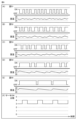
- FIG. 5 is a diagram showing the change in room temperature of each room and the change in the number of thermo-ON units in the comparative refrigeration cycle device.
- FIG. 6 is a diagram showing the change in room temperature of each room and the change in the number of thermo-ON units in the refrigeration cycle device 1 of the present embodiment.
- the capacity of the refrigeration cycle device 1 applied in the simulation will be explained.
- the number of indoor units is "five", and the five indoor units are arranged in the five corresponding rooms. That is, in the example of FIG. 1, indoor units 31 to 35 are arranged in rooms 51 to 55, respectively.
- the capacity of all five indoor units is standardized at 4.5 kW.
- the loads of the five rooms are 2 kW, 2.5 kW, 3 kW, 3.5 kW, and 4 kW, respectively.
- the set temperature of the five indoor units is 27 degrees, and the initial temperature of the five rooms is 27 degrees.
- the control device executes thermo OFF control when the detected temperature (room temperature) reaches a temperature 0.5 degrees lower than the set temperature (i.e., the detected temperature reaches 26.5 degrees). In the refrigeration cycle device of the comparative example, the control device executes thermo ON control when the detected temperature (room temperature) reaches a temperature 0.5 degrees higher than the set temperature (i.e., the detected temperature reaches 27 degrees).
- the first and second cycles in the refrigeration cycle device 1 of this embodiment are 3 minutes and 1 minute, respectively.
- Figures 5(A)-(E) and Figures 6(A)-(E) respectively show the thermo-ON and thermo-OFF states of each indoor unit in rooms 51-55.
- the lower parts of Figures 5(A)-(E) and Figures 6(A)-(E) show the room temperatures in rooms 51-55.
- Figures 5(F) and 6(F) show the change in the number of units with the thermo-ON.
- the horizontal axis of Figures 5(A)-(F) and Figures 6(A)-(F) shows time.
- the number of thermo-ON units varies within a range of 0 to 5 units.
- the range of variation in the number of thermo-ON units is large in the refrigeration cycle device of the comparative example.
- the reason for this variation depends on the indoor temperatures of the multiple indoor units, so the control device executes thermo-ON and thermo-OFF for each indoor unit independently. Therefore, the thermo-ON timing and thermo-OFF timing of each indoor unit are accidental and follow the flow. Therefore, in the refrigeration cycle device of the comparative example, the number of thermo-ON units may be excessive, in which case the instantaneous capacity of the heat source unit may become excessive, and the coefficient of performance of the refrigeration cycle device may decrease.
- the number of thermo-ON units can be changed in increments of three or four units.
- the refrigeration cycle apparatus 1 of this embodiment can reduce the maximum value of the number of thermo-ON units and the range of change in the number of thermo-ON units compared to the refrigeration cycle apparatus of the comparative example. This is because the refrigeration cycle apparatus 1 of this embodiment executes thermo-ON control based on the first difference in all of the multiple indoor units.
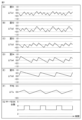
- FIG. 7 is a diagram showing changes in ⁇ T for chambers 51 to 55 in the refrigeration cycle device 1 of this embodiment.
- FIGS. 7(A) to 7(E) show changes in the first difference values ⁇ Ta1 to ⁇ Ta5 for chambers 51 to 55, respectively.
- FIG. 7(F) shows changes in the average value ⁇ Ta of the first difference values.
- FIG. 7(G) shows changes in the number of thermo-ON units, and is a diagram similar to FIG. 6(F).
- the refrigerant circulating flow rate passing through the outdoor heat exchanger 40 of the heat source unit 2 can be reduced, and the heat transfer area of the outdoor heat exchanger 40 of the heat source unit 2 can be increased relative to the refrigerant circulating flow rate. Therefore, when the number of indoor units with the thermostat turned on is small, the coefficient of performance of the refrigeration cycle device 1 can be improved more than when the number of indoor units with the thermostat turned on is large.
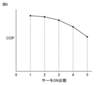
- FIG. 8 is a diagram showing the relationship between the number of thermo-ON units and the coefficient of performance (COP).
- the vertical axis indicates the coefficient of performance
- the horizontal axis indicates the number of thermo-ON units.
- the example of FIG. 8 shows that when the number of indoor units with thermo-ON is small, the coefficient of performance of the refrigeration cycle device 1 is improved more than when the number of indoor units with thermo-ON is large.
- the average COP of the refrigeration cycle device 1 of this embodiment in which the fluctuation range of the number of thermo-ON units is small, is higher than the average COP of the refrigeration cycle device of the comparative example, in which the fluctuation range of the number of thermo-ON units is large.
- the control device 300 executes the first process (the number process in step S4 in FIG. 3).
- the first process is a process for determining the number of indoor units (the number S with thermo-ON) to be operated among the N indoor units 31 to 3N based on a plurality of first difference values ⁇ Ta1 to ⁇ TaN.
- the plurality of first difference values ⁇ Ta1 to ⁇ TaN are difference values between the detected temperatures T1 to TN (indoor temperatures) of the N rooms 51 to 5N and the set temperatures Ts1 to TsN corresponding to the detected temperatures.
- the control device 300 executes the second process (the process in step S8 in FIG.
- the number of indoor units to be operated is determined based on the detected temperatures of each of the multiple indoor units and multiple difference values between the detected temperatures and the corresponding set temperatures, and the determined number of indoor units are operated as operating indoor units. Therefore, for example, the coefficient of performance of the refrigeration cycle device can be improved compared to the refrigeration cycle device of the comparative example described above (see the explanations of Figures 5 to 8).
- the control device 300 executes the first process (the process for the number of units in S4 in FIG. 3) for each first period (step S2 in FIG. 3).
- the control device 300 also executes the second process (the process for step S8 in FIG. 3) for each second period (step S6 in FIG. 3).
- the control device 300 calculates multiple (N) first difference values ⁇ Ta1 to ⁇ TaN by subtracting the set temperatures Ts1 to TsN corresponding to the detected temperatures from the detected temperatures T1 to TN of each of the N indoor units.
- step S28 the control device 300 determines that the number of operating indoor units is too low, and that the average value tends to move away from the desirable value of "0". Therefore, if this is the case, the average value can be brought closer to "0" by increasing the number of operating units in step S30.
- the average value ⁇ Ta is negative (YES in step S32)
- the number of operating units is too high, and that the average value tends to move away from the desirable value of "0”. Therefore, by decreasing the number of operating units in step S34, the power consumption can be reduced and the average value can be brought closer to "0".
- the second process shown in step S8 in FIG. 3 is a process for determining the indoor unit to be operated from among the N indoor units 31 to 3N in order of the indoor unit with the largest first difference value (giving priority to indoor units with large first difference values). Therefore, the refrigeration cycle device 1 can reduce the degree of deviation between the detected temperature and the set temperature by operating an indoor unit with a large degree of deviation.
- the control device 300 controls the operating frequency of the motor of the compressor 10 so that the refrigerant pressure (refrigerant evaporation pressure) of the operating indoor units 3s becomes a predetermined value regardless of the number of indoor units with the thermo-ON.
- the control device 300 can automatically lower the compressor frequency in response to a decrease in the number of indoor units with the thermo-ON.
- the heat transfer area of the outdoor heat exchanger 40 of the heat source unit 2 can be increased relative to the refrigerant circulating flow rate. Therefore, when the number of indoor units with the thermo-ON is small, the coefficient of performance of the refrigeration cycle device 1 can be improved more than when the number of indoor units with the thermo-ON is large.
- step S4 in Fig. 3 is replaced by step S4A.
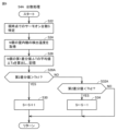
- Fig. 9 is a flowchart of the number processing in step S4A. Comparing Fig. 9 with Fig. 4, steps S28 and S32 in Fig. 4 are replaced by steps S28A and S32A, respectively, in the flowchart in Fig. 9.
- control device 300 does not execute the process of determining whether ⁇ Ta>0 in step S28A, and does not execute the process of determining whether ⁇ Ta ⁇ 0 in step S32A.
- control device 300 may determine whether the second difference value is greater than the first threshold value Th1 in step S28A, and determine whether the second difference value is less than the second threshold value Th2 in step S32A.
- the refrigeration cycle apparatus 1 of the above embodiment uses the average value ⁇ Ta of the first difference values ⁇ Ta1 to ⁇ TaN.
- the refrigeration cycle apparatus 1 may use another value based on the first difference values ⁇ Ta1 to ⁇ TaN instead of the average value ⁇ Ta.
- the other value may be, for example, a total value of the first difference values ⁇ Ta1 to ⁇ TaN.
- the other value may be a multiplication value of the first difference values ⁇ Ta1 to ⁇ TaN.
- the first threshold value Th1 in step S28 of FIG. 4 may be a positive value that is very close to "0". In this case, the process of determining whether the second difference value is greater than the first threshold value Th1 is replaced by a process of determining whether the currently calculated ⁇ Ta is greater than the previously calculated ⁇ Ta. Also, the second threshold value Th2 in step S32 of FIG. 4 may be a negative value that is very close to "0". In this case, the process of determining whether the second difference value is smaller than the second threshold value Th2 is replaced by a process of determining whether the currently calculated ⁇ Ta is smaller than the previously calculated ⁇ Ta.
- 1 refrigeration cycle device 1 refrigeration cycle device, 2 heat source unit, 3 indoor unit, 3s operating indoor unit, 4 temperature sensor, 10 compressor, 10a refrigerant inlet, 10b refrigerant outlet, 11 electronic expansion valve, 20 indoor heat exchanger, 21 indoor fan, 40 outdoor heat exchanger, 61 outdoor fan, 100 four-way valve, 300 control device, 302 memory, 303 communication interface, 312 receiving unit, 314 processing unit, 316 storage unit, 318 transmitting unit.
Landscapes
- Engineering & Computer Science (AREA)
- Chemical & Material Sciences (AREA)
- Combustion & Propulsion (AREA)
- Mechanical Engineering (AREA)
- General Engineering & Computer Science (AREA)
- Air Conditioning Control Device (AREA)
Abstract
Description
本開示は、冷凍サイクル装置、および冷凍サイクル装置の制御方法に関する。 This disclosure relates to a refrigeration cycle device and a method for controlling a refrigeration cycle device.
たとえば、特開平10-9689号公報には、冷蔵ユニットが開示されている。この冷蔵ユニットは、室内機、および熱源機などを有する。この冷凍ユニットは、設定温度を記憶するとともに、室内機の室内温度を検出する。そして、冷凍ユニットは、室内温度が検出温度よりも大きい場合に、室内機による冷却を実行する(サーモON制御を実行する)。一方、冷凍ユニットは、室内温度が検出温度よりも小さい場合に、室内機による冷却を停止する(サーモOFF制御を実行する)。 For example, Japanese Patent Application Laid-Open Publication No. 10-9689 discloses a refrigeration unit. This refrigeration unit has an indoor unit, a heat source unit, and the like. This refrigeration unit stores a set temperature and detects the indoor temperature of the indoor unit. Then, when the indoor temperature is higher than the detected temperature, the refrigeration unit performs cooling by the indoor unit (performs thermo ON control). On the other hand, when the indoor temperature is lower than the detected temperature, the refrigeration unit stops cooling by the indoor unit (performs thermo OFF control).
たとえば、1つの熱源機に複数の室内機が接続されるいわゆるマルチエアコンが存在する。上記の冷蔵ユニットの技術を、該マルチエアコンに適用する冷凍サイクル装置が考えられる。しかしながら、この冷凍サイクル装置では、複数の室内機のサーモONタイミングおよびサーモOFFタイミングは、該複数の室内機の室内温度に依存する。したがって、この冷凍サイクル装置では、サーモON制御が実行される室内機の数が過大に多くなる場合がある。この場合には、熱源機の能力が過大となり、冷凍サイクル装置の成績係数(COP:Coefficient Of Performance)が低下する場合がある。 For example, there are so-called multi-air conditioners in which multiple indoor units are connected to one heat source unit. A refrigeration cycle device can be considered in which the above-mentioned refrigeration unit technology is applied to such a multi-air conditioner. However, in this refrigeration cycle device, the thermo-ON timing and thermo-OFF timing of the multiple indoor units depend on the indoor temperatures of the multiple indoor units. Therefore, in this refrigeration cycle device, the number of indoor units for which thermo-ON control is executed may become excessively large. In this case, the capacity of the heat source unit may become excessive, and the coefficient of performance (COP) of the refrigeration cycle device may decrease.
本開示の目的は、成績係数を向上させる冷凍サイクル装置、および冷凍サイクル装置の制御方法を提供することである。 The objective of this disclosure is to provide a refrigeration cycle device that improves the coefficient of performance, and a method for controlling a refrigeration cycle device.
本実施の形態に係る冷凍サイクル装置は、熱源機と、複数の室内機と、制御装置と、複数の温度センサとを備える。熱源機は、冷媒を吐出する圧縮機を有する。制御装置は、複数の室内機の各々の設定温度を記憶するメモリを有する。複数の温度センサは、複数の室内機の各々が設置されている各室の温度を検出温度として検出する。前記制御装置は、前記複数の室内機の各々の検出温度と、該検出温度と対応する設定温度との複数の第1差分値に基づいて、前記複数の室内機のうち運転する室内機の運転台数を決定する第1処理を実行する。制御装置は、前記複数の室内機から前記運転台数の室内機を運転室内機として決定する第2処理を実行する。そして、制御装置は、前記運転室内機を運転する第3処理を実行する。 The refrigeration cycle device according to this embodiment includes a heat source unit, a plurality of indoor units, a control unit, and a plurality of temperature sensors. The heat source unit has a compressor that discharges a refrigerant. The control unit has a memory that stores the set temperature of each of the plurality of indoor units. The plurality of temperature sensors detect the temperature of each room in which each of the plurality of indoor units is installed as a detected temperature. The control unit executes a first process of determining the number of indoor units to be operated among the plurality of indoor units based on the detected temperature of each of the plurality of indoor units and a plurality of first difference values between the detected temperature and the corresponding set temperature. The control unit executes a second process of determining the indoor units of the operating number from the plurality of indoor units as operating indoor units. The control unit then executes a third process of operating the operating indoor units.
本開示の制御方法は、冷凍サイクル装置の制御方法である。冷凍サイクル装置は、熱源機と、複数の室内機と、制御装置と、複数の温度センサとを備える。熱源機は、冷媒を吐出する圧縮機を有する。制御装置は、複数の室内機の各々の設定温度を記憶するメモリを有する。複数の温度センサは、複数の室内機の各々が設置されている各室の温度を検出温度として検出する。制御方法は、複数の室内機の各々の検出温度と、該検出温度と対応する設定温度との複数の第1差分値に基づいて、前記複数の室内機のうち運転する室内機の運転台数を決定することを備える。制御方法は、複数の室内機から前記運転台数の室内機を運転室内機として決定することを備える。そして、制御方法は、運転室内機を運転することを備える。 The control method disclosed herein is a method for controlling a refrigeration cycle device. The refrigeration cycle device includes a heat source unit, a plurality of indoor units, a control unit, and a plurality of temperature sensors. The heat source unit has a compressor that discharges a refrigerant. The control unit has a memory that stores the set temperatures of the plurality of indoor units. The plurality of temperature sensors detect the temperature of each room in which each of the plurality of indoor units is installed as a detected temperature. The control method includes determining the number of indoor units to be operated among the plurality of indoor units based on the detected temperature of each of the plurality of indoor units and a plurality of first difference values between the detected temperature and the corresponding set temperature. The control method includes determining the operating number of indoor units from the plurality of indoor units as operating indoor units. The control method then includes operating the operating indoor units.
本開示によれば、成績係数を向上させることができる。 This disclosure makes it possible to improve the coefficient of performance.
以下、本発明の実施の形態について、図面を参照しながら詳細に説明する。以下では、複数の実施の形態について説明するが、各実施の形態で説明された構成を適宜組合わせることは出願当初から予定されている。なお、図中同一又は相当部分には同一符号を付してその説明は繰返さない。 Below, the embodiments of the present invention will be described in detail with reference to the drawings. Several embodiments will be described below, but it is planned from the beginning of the application that the configurations described in each embodiment will be appropriately combined. Note that the same or corresponding parts in the drawings will be given the same reference numerals and their description will not be repeated.
実施の形態1.
図1は、実施の形態1に係る冷凍サイクル装置1の冷媒回路を示す図である。図1を参照して、冷凍サイクル装置1は、熱源機2と、N(Nは2以上の整数)個の室内機とを備える。N個の室内機は、室内機31~室内機3Nとも称される。また、室内機31~室内機3Nは、それぞれ、室51~室5Nに配置される。さらに、冷凍サイクル装置1は、管89,90,92,94,96,97,98,99を備える。冷凍サイクル装置1は、ユーザなどの設定により、冷房運転および暖房運転を実行可能である。
Fig. 1 is a diagram showing a refrigerant circuit of a
熱源機2は、圧縮機10と、室外熱交換器40と、室外ファン61と、四方弁100と、制御装置300とを備える。室内機31~室内機3Nは、それぞれ、室内ファン211~21Nと、室内熱交換器201~20Nと、電子膨張弁(LEV:Linear Expansion Valve)111~11Nとを有する。なお、以下では、室内機31~室内機3N、室内ファン211~21N、室内熱交換器201~20N、および電子膨張弁111~11Nは、それぞれ、まとめて、室内機3、室内ファン21、室内熱交換器20、および電子膨張弁11とも称される。
The
管89は、四方弁100のポートHと熱源機2のガス側冷媒管接続口とを接続する。管90は、熱源機2のガス側冷媒管接続口と、室内熱交換器201~20NのそれぞれのポートP11~P1Nとを接続する。
Tube 89 connects port H of four-
管92は、熱源機2の液側冷媒管接続口と、電子膨張弁111~11Nとを接続する。管94は、熱源機2の液側冷媒管接続口と室外熱交換器40のポートP3とを接続する。管96は、室外熱交換器40のポートP4と四方弁100のポートFとを接続する。管98は、圧縮機10の冷媒入口10aと四方弁100のポートEとを接続する。管99は、圧縮機10の冷媒出口10bと四方弁100のポートGとの間に接続される。
Tube 92 connects the liquid side refrigerant pipe connection port of the
室内機31~3Nの内部で、それぞれ、室内熱交換器201~20Nと電子膨張弁111~11Nとが接続される。 Inside the indoor units 31-3N, the indoor heat exchangers 201-20N are connected to the electronic expansion valves 111-11N, respectively.
制御装置300は、各種センサの出力、およびリモートコントローラなどから送信される運転指令信号などに応じて、圧縮機10と、四方弁100と、電子膨張弁11と、室外ファン61と、室内ファン21などを制御する。リモートコントローラは、ユーザなどにより操作される。なお、図1の例では、温度センサ41~4N(温度センサ4)の各々が検出した温度T1~TNが制御装置300に入力されていることが記載されている。また、図1の例では、制御装置300が、圧縮機10、および電子膨張弁111~11N(電子膨張弁11)の各々に制御信号を出力することが示されている。
The
制御装置300は、CPU(Central Processing Unit)301、メモリ302、通信インタフェース303などを含む。メモリ302は、たとえば、ROM(Read Only Memory)、およびRAM(Random Access Memory)を有する。なお、制御装置300の制御については、ソフトウェアによる処理に限られず、専用のハードウェア(電子回路)で処理することも可能である。
The
圧縮機10は、冷媒入口10aから吸入された冷媒を圧縮する。そして、圧縮機10は、圧縮した冷媒を冷媒出口10bから吐出する。圧縮機10は、制御装置300から受ける制御信号によって運転周波数を変更するように構成される。圧縮機10のモータの運転周波数を変更することにより圧縮機10の出力が調整される。圧縮機10には種々のタイプ、たとえば、ロータリータイプ、往復タイプ、スクロールタイプ、スクリュータイプが採用され得る。
The
たとえば、制御装置300は、冷房運転中には、冷媒の蒸発温度(ET:Evaporating Temperature)が所定の目標値に到達するように、圧縮機10の運転周波数を制御する。蒸発温度の所定の目標値は、たとえば、0度とされる。また、制御装置300は、暖房運転中には、冷媒の凝縮温度(CT: Condensation Temperature)が所定の目標値に到達するように、圧縮機10の運転周波数を制御する。凝縮温度の所定の目標値は、たとえば、45度とされる。
For example, during cooling operation, the
四方弁100は、制御装置300から受ける制御信号によって状態A(冷房運転状態)および状態B(暖房運転状態)のいずれかになるように制御される。状態Aは、ポートEとポートHとが連通し、ポートFとポートGとが連通する状態である。状態Bは、ポートEとポートFとが連通し、ポートHとポートGとが連通する状態である。状態A(冷房運転状態)で圧縮機10を運転することによって、実線矢印に示す向きに冷媒が冷媒回路中を循環する。また、状態B(暖房運転状態)で圧縮機10を運転することによって、破線矢印に示す向きに冷媒が冷媒回路中を循環する。
The four-
電子膨張弁11の開度は、制御装置300から受ける制御信号によって、全開、SH(スーパーヒート:過熱度、Super Heat)制御、SC(サブクール:過冷却度、Sub Cool)制御または閉止(全閉)のいずれかを行なうように制御される。
The opening of the electronic expansion valve 11 is controlled by a control signal received from the
制御装置300は、冷房運転中には、室内機3の冷媒出口のSHが所定の目標値に到達するように、電子膨張弁11の開度を調整する。また、制御装置300は、暖房運転中には、室内機3の冷媒出口のサブクールが所定の目標値に到達するように、電子膨張弁11の開度を調整する。所定の目標値は、たとえば、3度である。なお、図1においては、スーパーヒートおよびサブクールを検出するためのセンサは記載されていない。
During cooling operation, the
温度センサ41~4Nは、それぞれ、室51~5Nの室内温度を検出温度T1~TNとして検出する。なお、図1の例では、温度センサ41~4Nは、それぞれ、室内機31~3Nに設置されている例が示されている。しかしながら、温度センサ41~4Nは、室51~5Nの室内温度を検出できるのであれば、他の場所に設置されていてもよい。温度センサ41~4Nは、それぞれ、室内機31~3Nの外部に設置されていてもよい。また、温度センサ41~4Nは、それぞれ、室内機31~3Nの各々に対応するリモートコントローラに設置されていてもよい。
The
室内ファン21のファン回転速度は、制御装置300から受ける制御信号によって、駆動する。ファン回転速度は省エネと騒音のバランスを考慮して設計された固定値で制御される。
The fan rotation speed of the indoor fan 21 is driven by a control signal received from the
圧縮機10から圧縮されて吐出された冷媒の少なくとも一部の冷媒を、電子膨張弁11の開放などにより室内熱交換器20に流入させる制御は「第1制御」とも称される。第1制御は、「サーモON制御」とも称される。サーモON制御は、本開示の「室内機を運転する制御」に対応する。また、圧縮機10から圧縮されて吐出された冷媒を、電子膨張弁11の閉塞などにより室内熱交換器20に流入させない制御は「第2制御」とも称される。第1制御は、「サーモOFF制御」とも称される。サーモOFF制御は、本開示の「室内機の運転を停止する制御」に対応する。
The control of allowing at least a portion of the refrigerant compressed and discharged from the
制御装置300は、圧縮機10の運転(圧縮機10の運転周波数)、電子膨張弁111~11Nの開閉(開度の調整)、および室内ファン211~21Nの駆動により、各室内機31~3NのサーモONおよびサーモOFF(第1制御および第2制御)を実行する。
The
[制御装置300の機能ブロック図]
図2は、制御装置300の機能ブロック図である。制御装置300は、受信部312と、処理部314と、記憶部316と、送信部318とを有する。受信部312と、送信部318とは、図1の通信インタフェース303に対応する。処理部314は、CPU301に対応する。記憶部316は、メモリ302に対応する。
[Functional block diagram of the control device 300]
Fig. 2 is a functional block diagram of the
上述のように、温度センサ41~4Nは、それぞれ、室51~5Nの温度を検出温度T1~TNとして検出する。検出温度T1~TNは、制御装置300に入力され、該制御装置300の受信部312は、該検出温度T1~TNを受信する。該検出温度T1~TNは、処理部314に出力される。
As described above, temperature sensors 41-4N detect the temperatures of chambers 51-5N as detected temperatures T1-TN, respectively. The detected temperatures T1-TN are input to the
記憶部316には、室内機31~3Nの各々の設定温度Ts1~TsNが記憶されている。設定温度Ts1~TsNは、たとえば、ユーザ(冷凍サイクル装置1の管理者など)により設定される。また、記憶部316に記憶されている「前回のΔTa」については後述する。
The
処理部314は、冷凍サイクル装置1のCOPを向上させるように、台数処理と、決定処理とを実行する。台数処理は、運転させる(サーモONさせる)室内機3の台数(運転台数)を決定する処理である。「運転台数」は、「サーモON台数」とも称される。処理部314は、第1周期毎に台数処理を実行する。本実施の形態においては、第1周期は、後述の図3のステップS2により示されるように「3分」である。
The
決定処理は、台数処理により決定されたサーモON台数で、サーモONさせる室内機を決定する処理である。処理部314は、第2周期毎に決定処理を実行する。本実施の形態においては、第2周期は、第1周期よりも短く、後述の図3のステップS6により示されるように「1分」である。
The determination process is a process for determining which indoor units will have their thermostats turned ON, based on the number of units with their thermostats turned ON determined by the unit count process. The
[フローチャート]
図3は、制御装置300の主な処理を示すフローチャートである。図3のフローチャートは、たとえば、定期的(たとえば、1秒毎)に実行される。まず、ステップS2において、制御装置300は、前回の(直近の)台数処理の実行から、3分(第1周期)経過したか否かを判断する。前回の台数処理の実行から、3分経過していない場合には(ステップS2でNO)、図3の処理は終了する。前回の(直近の)台数処理の実行から、3分経過した場合には、処理は、ステップS4に進む。ステップS4においては、制御装置300は、サーモON台数Sを決定する。ステップS4の詳細は、後述の図4で説明される。
[flowchart]
FIG. 3 is a flowchart showing the main processing of the
次に、ステップS6において、制御装置300は、前回の(直近の)決定処理の実行から、1分(第2周期)経過したか否かを判断する。前回の(直近の)決定処理の実行から、1分経過していない場合には(ステップS6でNO)、図3の処理を終了する。前回の(直近の)決定処理の実行から、1分経過した場合には、処理は、ステップS8に進む。
Next, in step S6, the
ステップS8においては、制御装置300は、決定処理を実行する。具体的には、制御装置300は、ステップS4の台数処理により決定されたサーモON台数Sの室内機を決定する。本実施の形態においては、制御装置300は、N個の室内機3から、第1差分値ΔTが大きいS個の室内機を優先して「運転室内機3s」として決定する処理を、決定処理として実行する。「運転室内機3s」は、サーモONさせる室内機である。差分値ΔTについては後述する。
In step S8, the
次に、ステップS10において、制御装置300は、ステップS8で決定された運転室内機3sを実際に運転させる(該運転室内機に対してサーモON制御を実行する)。具体的には、ステップS10においては、制御装置300は、運転室内機3sの冷媒の圧力(冷媒の蒸発圧力)が所定値となるように圧縮機10のモータの運転周波数を制御する処理を実行する。
Next, in step S10, the
ここで、所定値を説明する。例えば冷房運転中は、たとえば、冷媒の蒸発温度が第1所定温度(たとえば、0度)に相当する冷媒圧力が所定値とされる。また、制御装置300は、所定パラメータ(外気温など)に基づいて熱負荷を予測し、熱負荷が小さければより高い蒸発温度(例えば10度)に相当する冷媒圧力を所定値とするようにしてもよい。また、暖房運転中においては、凝縮温度が第2所定温度(たとえば、45度)に相当する冷媒圧力が、所定値とされる。また、上記所定パラメータに基づいて熱負荷を予測し、熱負荷が小さいと予想されれば、第2所定温度より低い凝縮温度(例えば40度)に相当する冷媒圧力を所定値としてもよい。
Here, the predetermined value will be explained. For example, during cooling operation, the refrigerant pressure at which the evaporation temperature of the refrigerant corresponds to a first predetermined temperature (for example, 0 degrees) is set as the predetermined value. The
また、ステップS10においては、制御装置300は、運転室内機3sの電子膨張弁11sの開度の調整、および運転室内機3sの室内ファン21sの駆動を実行する。
In addition, in step S10, the
図4は、ステップS4の台数処理の主なフローチャートである。ステップS22において、制御装置300は、現時点でのサーモON台数Sを特定する。サーモON台数Sの特定については、たとえば、制御装置300は、サーモONしている室内機の室内機ID(identification)をメモリ302のRAMに格納する。そして、ステップS22においては、RAMの室内機IDを確認することにより、サーモON台数Sを特定する。なお、ステップS22で特定されたサーモON台数Sは、本開示の「現時点の運転室内機の台数」に対応する。
FIG. 4 is a main flowchart of the number processing in step S4. In step S22, the
次に、ステップS24において、制御装置300は、N個の全ての室内機31~3Nの各々の検出温度T1~TNを、温度センサ41~4Nから取得する。次に、ステップS26において、処理部314は、取得した検出温度T1~TNと、該検出温度と対応する設定温度Ts1~TsNとの複数の第1差分値ΔTa1~ΔTaNを算出する。具体的には、処理部314は、検出温度T1と設定温度Ts1との第1差分値ΔTa1を算出し、検出温度T2と設定温度Ts2との第1差分値ΔTa2を算出し、...、検出温度TNと設定温度TsNとの第1差分値ΔTaNを算出する。
Next, in step S24, the
ここで、第1差分値の算出の詳細を説明する。冷凍サイクル装置1が冷房運転を実行している場合には、第1差分値ΔTa1~ΔTaNは、検出温度から設定温度を差引いた値とする。冷凍サイクル装置1が暖房運転を実行している場合には、第1差分値ΔTa1~ΔTaNは、設定温度から検出温度を差引いた値とする。
Here, the calculation of the first difference value will be described in detail. When the
さらに、制御装置300は、第1差分値ΔTa1~ΔTaNの平均値ΔTaを算出する。つまり、処理部314は、冷房運転中には、以下の式(1)により、平均値ΔTaを算出する。
Furthermore, the
なお、制御装置300は、暖房運転中には、上記の式(1)の右辺の分子が、「Tsn-Tn」となる。さらに、ステップS26においては、制御装置300は、平均値ΔTaを算出する毎に記憶部316に該平均値ΔTaを前回の平均値ΔTa(図2参照)として記憶する。ステップS26の処理が終了すると、処理は、ステップS28に進む。
Note that during heating operation, the numerator on the right side of the above formula (1) becomes "Tsn-Tn". Furthermore, in step S26, each time the
次に、ステップS28の処理を説明する。平均値ΔTaは、現在温度(検出温度)と設定温度との、N台の室内機3の全体的な乖離度(差分)を示す値である。この平均値ΔTaが徐々に増加している場合には、当該乖離度が増加しているということであることから、サーモON台数を増加させて該乖離度を減少させることが好ましい。一方、この平均値ΔTaが徐々に減少している場合には、当該乖離度が減少しているということであることから、サーモON台数を減少させて消費電力を減少させることが好ましい。
Next, the processing of step S28 will be described. The average value ΔTa is a value indicating the overall deviation (difference) of the N
以下、ステップS28の具体的な処理を説明する。ステップS28においては、処理部314は、「今回算出した平均値ΔTa」から「前回算出した平均値ΔTa」から差引いた差分値を算出する。該差分値が、本開示の「第2差分値」に対応する。また、以下の処理では、予め規定された第1閾値Th1および第2閾値Th2が用いられる。第1閾値Th1は正の値であり、第2閾値Th2は負の値である。
The specific processing of step S28 will be described below. In step S28, the
この第2差分値が第1閾値Th1よりも大きい場合とは、今回算出された平均値ΔTaが前回算出された平均値ΔTaよりも増加している(上記乖離度が増加している)場合ということである。したがって、制御装置300は、サーモON台数を増加させて該乖離度を減少させる。
When this second difference value is greater than the first threshold value Th1, this means that the average value ΔTa calculated this time is greater than the average value ΔTa calculated last time (the deviation degree has increased). Therefore, the
一方、この第2差分値が第2閾値Th2よりも小さい場合には、今回算出された平均値ΔTaが前回算出された平均値ΔTaよりも減少している(上記乖離度が減少している)場合ということである。したがって、制御装置300は、サーモON台数を減少させて消費電力を減少させる。
On the other hand, if this second difference value is smaller than the second threshold value Th2, this means that the average value ΔTa calculated this time is smaller than the average value ΔTa calculated previously (the deviation degree is reduced). Therefore, the
さらに、ステップS28およびステップS32においては、制御装置300は、今回算出された平均値ΔTaを用いる。具体的には、平均値ΔTaが正および負のいずれであるかを特定する。一般的に、平均値ΔTaは“0”に近い方が好ましい。したがって、今回算出された平均値ΔTaが正である場合において、サーモON台数を多くして平均値ΔTaを“0”に近づけるようにする。一方、今回算出された平均値ΔTaが負である場合において、サーモON台数を少なくして、消費電力を減少させつつ平均値ΔTaを“0”に近づけるようにする。
Furthermore, in steps S28 and S32, the
以上の説明を踏まえて、ステップS28において、制御装置300は、第2差分値が第1閾値Th1よりも大きく、かつΔTaが正であるか否かを判断する。ステップS28でYESである場合、つまり、第2差分値が第1閾値Th1よりも大きく、かつΔTaが正である場合には、処理は、ステップS30に進む。一方、ステップS28でNOと判断された場合には、処理は、ステップS32に進む。
In light of the above explanation, in step S28, the
ステップS32において、制御装置300は、第2差分値が第2閾値Th2よりも小さく、かつΔTaが負であるか否かを判断する。ステップS32でYESである場合、つまり、第2差分値が第2閾値Th2よりも小さく、かつΔTaが負である場合には、処理は、ステップS34に進む。一方、ステップS32でNOと判断された場合には、ステップS4の処理は終了する。
In step S32, the
ステップS30においては、制御装置300は、現時点のサーモON台数S(ステップS22で特定したサーモON台数S)から1台増加させることにより算出された値を、サーモON台数Sとして決定する。また、ステップS32においては、制御装置300は、現時点のサーモON台数S(ステップS22で特定したサーモON台数S)から1台減少させることにより算出された値を、サーモON台数Sとして決定する。ステップS30の処理は、本開示の「第1台数処理」に対応する。ステップS32の処理は、本開示の「第2台数処理」に対応する。また、ステップS32でNOと判断された場合には、制御装置300は、現時点のサーモON台数Sを変更させないように決定する。該決定は、本開示の「第3台数処理」に対応する。
In step S30, the
[本実施の形態の冷凍サイクル装置が奏する効果]
次に、本実施の形態の冷凍サイクル装置1が奏する効果を説明するためのシミュレーション結果を説明する。以下では、1つの熱源機に複数の室内機が接続されるいわゆるマルチエアコンに対して、特開平10-9689号公報に記載の思想を適用した冷凍サイクル装置は、「比較例の冷凍サイクル装置」とも称される。図5は、比較例の冷凍サイクル装置における、各部屋の室温の変化、およびサーモON台数の変化を示す図である。図6は、本実施の形態の冷凍サイクル装置1における、各室の室温の変化、およびサーモON台数の変化を示す図である。
[Effects of the refrigeration cycle device of this embodiment]
Next, a simulation result for explaining the effect of the
次に、シミュレーションで適用された冷凍サイクル装置1の能力などを説明する。このシミュレーション結果では、冷凍サイクル装置1により冷房運転が実行された場合が説明される。また、室内機の台数は「5個」であり、該5個の室内機は、それぞれ、対応する5つの室に配置されている。つまり、図1の例では、室内機31~35が、それぞれ、室51~室55に配置されている。5個の室内機の能力は全て4.5kWで統一されている。5室の負荷は、それぞれ、2kW、2.5kW、3kW、3.5kW、および4kWである。5個の室内機の設定温度は27度であり、5室の初期温度は27度である。
Next, the capacity of the
比較例の冷凍サイクル装置においては、検出温度(室内温度)が設定温度から0.5度低い温度に到達した(つまり、検出温度が26.5度となった)タイミングで、制御装置はサーモOFF制御を実行する。また、比較例の冷凍サイクル装置においては、検出温度(室内温度)が、設定温度から0.5度高い温度に到達した(つまり、検出温度が27度となった)タイミングで、制御装置はサーモON制御を実行する。本実施の形態の冷凍サイクル装置1における第1周期および第2周期は、それぞれ、3分間および1分間とする。
In the refrigeration cycle device of the comparative example, the control device executes thermo OFF control when the detected temperature (room temperature) reaches a temperature 0.5 degrees lower than the set temperature (i.e., the detected temperature reaches 26.5 degrees). In the refrigeration cycle device of the comparative example, the control device executes thermo ON control when the detected temperature (room temperature) reaches a temperature 0.5 degrees higher than the set temperature (i.e., the detected temperature reaches 27 degrees). The first and second cycles in the
図5(A)~(E)および図6(A)~(E)の上部は、それぞれ、室51~55のそれぞれの各室内機のサーモONおよびサーモOFFを示す。図5(A)~(E)および図6(A)~(E)の下部は、室51~55の室温を示す。図5(F)および図6(F)は、サーモON台数の変化を示す。図5(A)~(F)および図6(A)~(F)の横軸は時間を示す。 The upper parts of Figures 5(A)-(E) and Figures 6(A)-(E) respectively show the thermo-ON and thermo-OFF states of each indoor unit in rooms 51-55. The lower parts of Figures 5(A)-(E) and Figures 6(A)-(E) show the room temperatures in rooms 51-55. Figures 5(F) and 6(F) show the change in the number of units with the thermo-ON. The horizontal axis of Figures 5(A)-(F) and Figures 6(A)-(F) shows time.
図5(F)に示すように、比較例の冷凍サイクル装置においては、サーモON台数は、0台~5台の幅で変化する。このように、比較例の冷凍サイクル装置においては、サーモON台数の変化幅は大きくなる。このように変化する理由については複数の室内機の室内温度に依存することから、制御装置は、各室内機が独立してサーモONおよびサーモOFFを実行する。したがって、各室内機のサーモONタイミングおよびサーモOFFタイミングは偶発的で成り行きとなる。よって、比較例の冷凍サイクル装置においては、サーモON台数が過多となる場合があり、この場合には熱源機の瞬時能力が過大となり、冷凍サイクル装置の成績係数が低下する場合がある。 As shown in FIG. 5(F), in the refrigeration cycle device of the comparative example, the number of thermo-ON units varies within a range of 0 to 5 units. In this way, the range of variation in the number of thermo-ON units is large in the refrigeration cycle device of the comparative example. The reason for this variation depends on the indoor temperatures of the multiple indoor units, so the control device executes thermo-ON and thermo-OFF for each indoor unit independently. Therefore, the thermo-ON timing and thermo-OFF timing of each indoor unit are accidental and follow the flow. Therefore, in the refrigeration cycle device of the comparative example, the number of thermo-ON units may be excessive, in which case the instantaneous capacity of the heat source unit may become excessive, and the coefficient of performance of the refrigeration cycle device may decrease.
一方、図6(F)に示すように、本実施の形態の冷凍サイクル装置1においては、サーモON台数は、3台または4台の幅での変化とすることができる。このように、本実施の形態の冷凍サイクル装置1は、比較例の冷凍サイクル装置よりも、サーモON台数の最大値およびサーモON台数の変化幅を小さくできる。何故なら、本実施の形態の冷凍サイクル装置1においては、複数の室内機の全てにおける第1差分に基づいて、サーモON制御を実行するからである。
On the other hand, as shown in FIG. 6 (F), in the
図7は、本実施の形態の冷凍サイクル装置1における、室51~55のΔTの変化などを示す図である。図7(A)~図7(E)は、それぞれ、室51~室55の第1差分値ΔTa1~ΔTa5の変化を示す。図7(F)は、第1差分値の平均値ΔTaの変化を示す。図7(G)は、サーモON台数の変化を示し、図6(F)と同様の図である。
FIG. 7 is a diagram showing changes in ΔT for
ところで、一般的に、サーモONされる室内機の数が少ない場合には、熱源機2の室外熱交換器40を通過する冷媒循環流量を減少させることができることから、熱源機2の室外熱交換器40の伝熱面積を冷媒循環流量に対して相対的に増大できる。したがって、サーモONされる室内機の数が少ない場合には、サーモONされる室内機の数が多い場合よりも、冷凍サイクル装置1の成績係数を向上させることができる。
In general, when the number of indoor units with the thermostat turned on is small, the refrigerant circulating flow rate passing through the
図8は、サーモON台数と、成績係数(COP)との関係を示す図である。図8の例においては、縦軸が成績係数を示し、横軸がサーモON台数を示す。図8の例では、上述したように、サーモONされる室内機の数が少ない場合には、サーモONされる室内機の台数が多い場合よりも、冷凍サイクル装置1の成績係数を向上されていることが示されている。ここで、一般的に、図8に示されているように、サーモONされる室内機の台数の減少に伴うCOPの向上は、鈍化(飽和)する特性がある。したがって、サーモON台数の変動幅が小さい本実施の形態の冷凍サイクル装置1の平均COPの方が、サーモON台数の変動幅が大きい比較例の冷凍サイクル装置の平均COPよりも高い。
FIG. 8 is a diagram showing the relationship between the number of thermo-ON units and the coefficient of performance (COP). In the example of FIG. 8, the vertical axis indicates the coefficient of performance, and the horizontal axis indicates the number of thermo-ON units. As described above, the example of FIG. 8 shows that when the number of indoor units with thermo-ON is small, the coefficient of performance of the
以上、本実施の形態の冷凍サイクル装置1は、比較例の冷凍サイクル装置よりも、サーモON台数の最大値を低減できることから、熱源機2の瞬時能力を低減できる。したがって、本実施の形態の冷凍サイクル装置1は、比較例の冷凍サイクル装置よりも成績係数を向上させることができる。また、本実施の形態の冷凍サイクル装置1は、比較例の冷凍サイクル装置よりも、サーモON台数の変動幅を低減できることから、比較例の冷凍サイクル装置よりも成績係数を向上させることができる。
As described above, the
[総括]
(1) 以上の説明のように、制御装置300は、第1処理(図3のステップS4の台数処理)を実行する。第1処理は、複数の第1差分値ΔTa1~ΔTaNに基づいて、N個の室内機31~3Nのうち運転する室内機の運転台数(サーモON台数S)を決定する処理である。複数の第1差分値ΔTa1~ΔTaNは、N個の室51~5Nの各々の検出温度T1~TN(室内温度)と、該検出温度と対応する設定温度Ts1~TsNとの差分値である。そして、制御装置300は、N個の室内機31~3Nから、運転台数(サーモON台数S)の室内機を運転室内機として決定する第2処理(図3のステップS8の処理)を実行する。そして、制御装置300は、第2処理により決定された運転室内機を運転する第3処理(図3のステップS10)を実行する。
[Summary]
(1) As described above, the
このような構成によれば、複数の室内機の各々の検出温度と、該検出温度と対応する設定温度との複数の差分値に基づいて、室内機の運転台数を決定し、該運転台数の室内機を運転室内機として運転する。したがって、たとえば、上記の比較例の冷凍サイクル装置と比較して冷凍サイクル装置の成績係数を向上させることができる(図5~図8の説明参照)。 With this configuration, the number of indoor units to be operated is determined based on the detected temperatures of each of the multiple indoor units and multiple difference values between the detected temperatures and the corresponding set temperatures, and the determined number of indoor units are operated as operating indoor units. Therefore, for example, the coefficient of performance of the refrigeration cycle device can be improved compared to the refrigeration cycle device of the comparative example described above (see the explanations of Figures 5 to 8).
(2) 制御装置300は、第1周期(図3のステップS2)毎に第1処理(図3のS4の台数処理)を実行する。また、制御装置300は、第2周期(図3のステップS6)毎に第2処理(図3のステップS8の処理)を実行する。制御装置300は、冷凍サイクル装置1が冷房運転を実行している場合には、N個の室内機の各々の検出温度T1~TNから、該検出温度と対応する設定温度Ts1~TsNを差引くことにより複数(N個)の第1差分値ΔTa1~ΔTaNを算出する。また、制御装置300は、冷凍サイクル装置1が暖房運転を実行している場合には、N個の室内機の各々の設定温度Ts1~TsNから、該設定温度と対応する検出温度T1~TNを差引くことにより複数(N個)の第1差分値ΔTa1~ΔTaNを算出する。そして、制御装置300は、台数処理として、図4に示すように、N個の第1差分値ΔTの平均値ΔTaを算出する(ステップS26および上記式(1)参照)。
(2) The
そして、制御装置300は、ステップS28において、今回算出した平均値から前回算出した平均値を差引いた第2差分値が第1閾値(正の値)よりも大きく(前回よりもΔTaが増加しており)、かつ今回された平均値ΔTaが正であるか否かを判断する。ステップS28でYESであるという第1状況である場合、制御装置300は、運転台数を、現時点の運転台数(ステップS22)から増加させるように決定する第1台数処理(ステップS30)を実行する。
Then, in step S28, the
また、制御装置300は、ステップS32において、第2差分値が負である第2閾値よりも小さく(前回よりもΔTaが減少しており)、かつ今回算出した平均値ΔTaが負であるか否かを判断する。ステップS32でYESであるという第2状況である場合、制御装置300は、運転台数を、現時点の運転台数(ステップS22)から減少させるように決定する第2台数処理(ステップS34)を実行する。
In addition, in step S32, the
このような構成によれば、制御装置300は、平均値ΔTaが増加傾向にある(ステップS28の第2差分値が第1閾値Th1よりも大きい)場合には、N台の室内機において、検出温度と設定温度との全体的な乖離度が増加しているということであることから、室内機の運転台数を増加させて該乖離度を減少させることができる。一方、平均値ΔTaが減少傾向にある(ステップS32の第2差分値が第2閾値Th2よりも小さい)場合には、N台の室内機において、検出温度と設定温度との全体的な乖離度が減少しているということであることから、室内機の運転台数を減少させつつ該乖離度を減少させることができる。したがって、本実施の形態の冷凍サイクル装置1は、第1台数処理および第2台数処理により、サーモON台数を適正化できる。
With this configuration, when the average value ΔTa is on the rise (the second difference value in step S28 is greater than the first threshold value Th1), the
さらに、制御装置300は、ステップS28において平均値ΔTaが正である場合には(ステップS28でYES)、運転されている室内機の運転台数が過少であり、該平均値の好ましい値である“0”から遠ざかる傾向にある。したがって、このような傾向である場合には、ステップS30で運転台数を増加させることにより、該平均値を“0”に近づけることができる。一方、平均値ΔTaが負である場合には(ステップS32でYES)、運転台数が過多であり、該平均値の好ましい値である“0”から遠ざかる傾向にある。したがって、ステップS34で運転台数を減少させることにより、消費電力を減少させるとともに該平均値を“0”に近づけることができる。
Furthermore, if the average value ΔTa is positive in step S28 (YES in step S28), the
(3) 制御装置300は、第1状況および第2状況のいずれとも異なる状況である場合(ステップS32でNOと判断された場合)、運転台数を変更させない(ステップS30およびステップS34のいずれも実行しない)。したがって、第1状況および第2状況のいずれとも異なる状況では、平均値ΔTaが適正な値であると想定されることから、運転台数を維持する。したがって、冷凍サイクル装置1は、適正な値である平均値ΔTaを維持できる。
(3) If the current situation is different from either the first situation or the second situation (if NO is determined in step S32), the
(4) ステップS30の第1台数処理は、運転台数を、現時点の運転台数から1台増加させるように決定する処理である。また、ステップS34の第2台数処理は、運転台数を、現時点の運転台数から1台減少させるように決定する処理である。したがって、制御装置300は、運転台数を増加させる処理および減少させる処理を共に簡易な処理とすることができる。
(4) The first number process in step S30 is a process for determining the number of operating vehicles to be increased by one from the current number of operating vehicles. The second number process in step S34 is a process for determining the number of operating vehicles to be decreased by one from the current number of operating vehicles. Therefore, the
(5) 図3のステップS8に示される第2処理は、N個の室内機31~3Nのうち第1差分値が大きい室内機から(第1差分値が大きい室内機を優先して)、運転室内機として決定する処理である。したがって、冷凍サイクル装置1は、検出温度と設定温度との乖離度が大きい室内機を運転することにより、該乖離度を減少することができる。
(5) The second process shown in step S8 in FIG. 3 is a process for determining the indoor unit to be operated from among the N
(6) 第2周期(図3のステップS6に示すように1分間)は、第1周期(図3のステップS2に示すように3分間)よりも短い。このように、第1周期が第2周期よりも長いことから、運転台数の増加および減少が頻繁に実行されることを抑制でき、圧縮機10の負担を軽減できる。また、第2周期が第1周期よりも短いことから、N個の室内機における検出温度と設定温度との差分値を抑制できる。
(6) The second period (one minute as shown in step S6 of FIG. 3) is shorter than the first period (three minutes as shown in step S2 of FIG. 3). As the first period is longer than the second period, frequent increases and decreases in the number of operating units can be suppressed, and the burden on the
(7) 制御装置300は、サーモON台数に関わらず運転室内機3sの冷媒の圧力(冷媒の蒸発圧力)が所定値となるように圧縮機10のモータの運転周波数を制御する。このような構成により室内機のサーモON台数の減少に応じて、制御装置300は、圧縮機の周波数を自動的に低下させることができる。冷媒循環量を減少させると、熱源機2の室外熱交換器40の伝熱面積を冷媒循環流量に対して相対的に増大できる。したがって、サーモONされる室内機の数が少ない場合には、サーモONされる室内機の数が多い場合よりも、冷凍サイクル装置1の成績係数を向上させることができる。
(7) The
実施の形態2.
実施の形態2においては、図3のステップS4がステップS4Aに代替される。図9は、ステップS4Aの台数処理のフローチャートである。図9と、図4と比較すると、図4のステップS28およびステップS32が、それぞれ、ステップS28AおよびステップS32Aに代替されたフローチャートが図9となる。
In the second embodiment, step S4 in Fig. 3 is replaced by step S4A. Fig. 9 is a flowchart of the number processing in step S4A. Comparing Fig. 9 with Fig. 4, steps S28 and S32 in Fig. 4 are replaced by steps S28A and S32A, respectively, in the flowchart in Fig. 9.
図9の例では、制御装置300は、ステップS28AにおいてはΔTa>0であるか否かを判断する処理を実行せず、かつステップS32AにおいてはΔTa<0であるか否かを判断する処理を実行しない。つまり、図9の例では、制御装置300は、ステップS28Aにおいては第2差分値が第1閾値Th1よりも大きいか否かを判断し、ステップS32Aにおいては第2差分値が第2閾値Th2よりも小さいか否かを判断するようにしてもよい。
In the example of FIG. 9, the
このような構成の場合には、第2差分値が第2閾値Th2よりも大きく第1閾値Th1よりも小さい場合、運転台数を変更させない(ステップS30およびステップS34の処理を実行しない)。したがって、実施の形態2の冷凍サイクル装置1は、平均値ΔTaが増加傾向および減少傾向のいずれでもない場合には、運転台数は適正であると想定されることから室内機の台数を維持できる。
In this configuration, if the second difference value is greater than the second threshold value Th2 and less than the first threshold value Th1, the number of operating units is not changed (the processes of steps S30 and S34 are not executed). Therefore, in the
以下に、実施の形態1および実施の形態2の変形例を説明する。
(1) 上述の実施形態の冷凍サイクル装置1は、第1差分値ΔTa1~ΔTaNの平均値ΔTaを用いた。しかしながら、冷凍サイクル装置1は、平均値ΔTaではなく、第1差分値ΔTa1~ΔTaNに基づいた他の値を用いてもよい。他の値は、たとえば、第1差分値ΔTa1~ΔTaNの合計値としてもよい。また、他の値は、第1差分値ΔTa1~ΔTaNの乗算値としてもよい。
Modifications of the first and second embodiments will be described below.
(1) The
(2) 図4のステップS28の第1閾値Th1は正でありかつ“0”に極めて近い値としてもよい。この場合には、第2差分値が第1閾値Th1より大きいか否かの処理は、今回算出されたΔTaは、前回算出されたΔTaよりも大きいか否かという判断処理に代替される。また、図4のステップS32の第2閾値Th2は負でありかつ“0”に極めて近い値としてもよい。この場合には、第2差分値が第2閾値Th2より小さいか否かの処理は、今回算出されたΔTaは、前回算出されたΔTaよりも小さいか否かという判断処理に代替される。 (2) The first threshold value Th1 in step S28 of FIG. 4 may be a positive value that is very close to "0". In this case, the process of determining whether the second difference value is greater than the first threshold value Th1 is replaced by a process of determining whether the currently calculated ΔTa is greater than the previously calculated ΔTa. Also, the second threshold value Th2 in step S32 of FIG. 4 may be a negative value that is very close to "0". In this case, the process of determining whether the second difference value is smaller than the second threshold value Th2 is replaced by a process of determining whether the currently calculated ΔTa is smaller than the previously calculated ΔTa.
今回開示された実施の形態は、すべての点で例示であって制限的なものではないと考えられるべきである。本発明の範囲は、上記した実施の形態の説明ではなくて請求の範囲によって示され、請求の範囲と均等の意味及び範囲内でのすべての変更が含まれることが意図される。 The embodiments disclosed herein should be considered in all respects as illustrative and not restrictive. The scope of the present invention is indicated by the claims, not by the description of the embodiments above, and is intended to include all modifications within the meaning and scope of the claims.
1 冷凍サイクル装置、2 熱源機、3 室内機、3s 運転室内機、4 温度センサ、10 圧縮機、10a 冷媒入口、10b 冷媒出口、11 電子膨張弁、20 室内熱交換器、21 室内ファン、40 室外熱交換器、61 室外ファン、100 四方弁、300 制御装置、302 メモリ、303 通信インタフェース、312 受信部、314 処理部、316 記憶部、318 送信部。 1 refrigeration cycle device, 2 heat source unit, 3 indoor unit, 3s operating indoor unit, 4 temperature sensor, 10 compressor, 10a refrigerant inlet, 10b refrigerant outlet, 11 electronic expansion valve, 20 indoor heat exchanger, 21 indoor fan, 40 outdoor heat exchanger, 61 outdoor fan, 100 four-way valve, 300 control device, 302 memory, 303 communication interface, 312 receiving unit, 314 processing unit, 316 storage unit, 318 transmitting unit.
Claims (10)
複数の室内機と、
前記複数の室内機の各々の設定温度を記憶するメモリを有する制御装置と、
前記複数の室内機の各々が設置されている各室の温度を検出温度として検出する複数の温度センサとを備え、
前記制御装置は、
前記複数の室内機の各々の検出温度と、該検出温度と対応する設定温度との複数の第1差分値に基づいて、前記複数の室内機のうち運転する室内機の運転台数を決定する第1処理を実行し、
前記複数の室内機から前記運転台数の室内機を運転室内機として決定する第2処理を実行し、
前記運転室内機を運転する第3処理を実行する、冷凍サイクル装置。 A heat source machine having a compressor that discharges a refrigerant;
A plurality of indoor units;
A control device having a memory that stores the set temperatures of each of the indoor units;
a plurality of temperature sensors that detect the temperature of each room in which the plurality of indoor units are installed as a detected temperature;
The control device includes:
execute a first process of determining the number of indoor units to be operated among the plurality of indoor units based on a plurality of first difference values between the detected temperatures of the plurality of indoor units and the set temperatures corresponding to the detected temperatures;
execute a second process of determining the number of indoor units in operation from the plurality of indoor units as operating indoor units;
A refrigeration cycle apparatus that executes a third process of operating the operating indoor unit.
第1周期毎に前記第1処理を実行し、
第2周期毎に前記第2処理を実行し、
前記複数の第1差分値は、
前記冷凍サイクル装置が冷房運転を実行している場合には、前記複数の室内機の各々の検出温度から、該検出温度と対応する設定温度を差引くことにより算出され、
前記冷凍サイクル装置が暖房運転を実行している場合には、前記複数の室内機の各々の設定温度から、該設定温度と対応する検出温度を差引くことにより算出され、
前記制御装置は、前記第1処理として、
前記複数の第1差分値の平均値を算出し、
今回算出した平均値から前回算出した平均値を差引いた第2差分値が正である第1閾値よりも大きい場合、前記運転台数を現時点の前記運転台数から増加させるように決定する第1台数処理を実行し、
前記第2差分値が負である第2閾値よりも小さい場合、前記運転台数を前記現時点の前記運転台数から減少させるように決定する第2台数処理を実行する、請求項1に記載の冷凍サイクル装置。 The control device includes:
execute the first process for each first period;
execute the second process every second period;
The plurality of first difference values are
When the refrigeration cycle device is performing a cooling operation, the temperature is calculated by subtracting a set temperature corresponding to the detected temperature from the detected temperature of each of the plurality of indoor units,
When the refrigeration cycle device is performing a heating operation, the temperature setting of each of the indoor units is calculated by subtracting the detected temperature corresponding to the set temperature from the set temperature of each of the indoor units,
The control device, as the first process,
Calculating an average value of the plurality of first difference values;
execute a first number-of-vehicles process to determine an increase in the number of operating vehicles from the current number of operating vehicles when a second difference value obtained by subtracting the previously calculated average value from the currently calculated average value is greater than a first threshold value that is positive;
The refrigeration cycle apparatus according to claim 1 , further comprising: a second number-of-units process for determining the number of operating units to be decreased from the current number of operating units when the second difference value is smaller than a negative second threshold value.
前記第2差分値が前記第1閾値よりも大きくかつ前記今回算出した前記平均値が正である第1状況である場合、前記第1台数処理を実行し、
前記第2差分値が前記第2閾値よりも小さくかつ前記今回算出した前記平均値が負である第2状況である場合、前記第2台数処理を実行する、請求項2に記載の冷凍サイクル装置。 The control device includes:
When the second difference value is greater than the first threshold value and the currently calculated average value is a positive value, the first number process is executed.
The refrigeration cycle apparatus according to claim 2 , wherein the second number process is executed in a second situation in which the second difference value is smaller than the second threshold value and the currently calculated average value is negative.
前記第2台数処理は、前記運転台数を、前記現時点の前記運転台数から1台減少させるように決定する処理である、請求項2~請求項5のいずれか1項に記載の冷凍サイクル装置。 The first number process is a process of determining the number of operating vehicles to be increased by one from the current number of operating vehicles,
The refrigeration cycle apparatus according to any one of claims 2 to 5, wherein the second number process is a process of determining the number of operating units to be reduced by one from the current number of operating units.
冷媒を吐出する圧縮機を有する熱源機と、
複数の室内機と、
前記複数の室内機の各々の設定温度を記憶するメモリを有する制御装置とを備え、
前記複数の室内機の各々は、該室内機が設置されている室の温度を検出温度として検出する温度センサを有し、
前記制御方法は、
前記複数の室内機の各々の検出温度と、該検出温度と対応する設定温度との複数の第1差分値に基づいて、前記複数の室内機のうち運転する室内機の運転台数を決定することと、
前記複数の室内機から前記運転台数の室内機を運転室内機として決定することと、
前記運転室内機を運転することとを備える、冷凍サイクル装置の制御方法。 A method for controlling a refrigeration cycle device, comprising:
A heat source machine having a compressor that discharges a refrigerant;
A plurality of indoor units;
a control device having a memory that stores the set temperatures of the indoor units,
Each of the indoor units has a temperature sensor that detects the temperature of a room in which the indoor unit is installed as a detected temperature,
The control method includes:
determining a number of indoor units to be operated among the plurality of indoor units based on a plurality of first difference values between the detected temperatures of the plurality of indoor units and the set temperatures corresponding to the detected temperatures;
determining the number of indoor units in operation from the plurality of indoor units as operating indoor units;
and operating the operating indoor unit.
Priority Applications (1)
| Application Number | Priority Date | Filing Date | Title |
|---|---|---|---|
| PCT/JP2023/030037 WO2025041232A1 (en) | 2023-08-21 | 2023-08-21 | Refrigeration cycle device and control method for refrigeration cycle device |
Applications Claiming Priority (1)
| Application Number | Priority Date | Filing Date | Title |
|---|---|---|---|
| PCT/JP2023/030037 WO2025041232A1 (en) | 2023-08-21 | 2023-08-21 | Refrigeration cycle device and control method for refrigeration cycle device |
Publications (1)
| Publication Number | Publication Date |
|---|---|
| WO2025041232A1 true WO2025041232A1 (en) | 2025-02-27 |
Family
ID=94731833
Family Applications (1)
| Application Number | Title | Priority Date | Filing Date |
|---|---|---|---|
| PCT/JP2023/030037 Pending WO2025041232A1 (en) | 2023-08-21 | 2023-08-21 | Refrigeration cycle device and control method for refrigeration cycle device |
Country Status (1)
| Country | Link |
|---|---|
| WO (1) | WO2025041232A1 (en) |
Citations (2)
| Publication number | Priority date | Publication date | Assignee | Title |
|---|---|---|---|---|
| JPH07318184A (en) * | 1994-05-23 | 1995-12-08 | Matsushita Electric Ind Co Ltd | Air conditioner |
| WO2020003447A1 (en) * | 2018-06-28 | 2020-01-02 | 三菱電機株式会社 | Air-conditioning system |
-
2023
- 2023-08-21 WO PCT/JP2023/030037 patent/WO2025041232A1/en active Pending
Patent Citations (2)
| Publication number | Priority date | Publication date | Assignee | Title |
|---|---|---|---|---|
| JPH07318184A (en) * | 1994-05-23 | 1995-12-08 | Matsushita Electric Ind Co Ltd | Air conditioner |
| WO2020003447A1 (en) * | 2018-06-28 | 2020-01-02 | 三菱電機株式会社 | Air-conditioning system |
Similar Documents
| Publication | Publication Date | Title |
|---|---|---|
| CN110671777B (en) | An air conditioner control method, device and air conditioner | |
| JP6642379B2 (en) | air conditioner | |
| US10830515B2 (en) | System and method for controlling refrigerant in vapor compression system | |
| US8522568B2 (en) | Refrigeration system | |
| KR101485601B1 (en) | Air conditioner and method of controlling the same | |
| US10941951B2 (en) | Systems and methods for temperature and humidity control | |
| JP6609417B2 (en) | Air conditioner | |
| JP6910554B2 (en) | Air conditioner and air conditioner | |
| CN100516711C (en) | Expansion valve control method for multi-system air conditioner | |
| KR20030097179A (en) | Heat-Pump Air Conditioner's Operating Method | |
| KR102558826B1 (en) | Air conditioner system and control method | |
| JP2004218879A (en) | Air conditioner and its control method | |
| CN103644621A (en) | Central arithmetic type multi-split air conditioner system and state switching control method thereof | |
| US20170030621A1 (en) | Low ambient cooling scheme and control | |
| JP6618609B2 (en) | Refrigeration equipment | |
| JP6672619B2 (en) | Air conditioning system | |
| JP2001272114A (en) | Refrigerant control of multi-room air conditioner | |
| WO2025041232A1 (en) | Refrigeration cycle device and control method for refrigeration cycle device | |
| JP2001241799A (en) | Multi-room air conditioner | |
| JPH09178247A (en) | Control device for multi-room air conditioner | |
| JP2754933B2 (en) | Multi-room air conditioner | |
| JP6245207B2 (en) | Air conditioner | |
| KR20050034080A (en) | Method for operating of multi type air-conditioner by install position of indoor-unit | |
| KR20190094017A (en) | Multi type air conditioner | |
| WO2024009434A1 (en) | Air conditioning device and air conditioning system |
Legal Events
| Date | Code | Title | Description |
|---|---|---|---|
| 121 | Ep: the epo has been informed by wipo that ep was designated in this application |
Ref document number: 23949693 Country of ref document: EP Kind code of ref document: A1 |
|
| NENP | Non-entry into the national phase |
Ref country code: DE |