WO2025041227A1 - Terminal, wireless communication method, and base station - Google Patents
Terminal, wireless communication method, and base station Download PDFInfo
- Publication number
- WO2025041227A1 WO2025041227A1 PCT/JP2023/030006 JP2023030006W WO2025041227A1 WO 2025041227 A1 WO2025041227 A1 WO 2025041227A1 JP 2023030006 W JP2023030006 W JP 2023030006W WO 2025041227 A1 WO2025041227 A1 WO 2025041227A1
- Authority
- WO
- WIPO (PCT)
- Prior art keywords
- csi
- model
- information
- monitoring
- resource
- Prior art date
- Legal status (The legal status is an assumption and is not a legal conclusion. Google has not performed a legal analysis and makes no representation as to the accuracy of the status listed.)
- Pending
Links
Images


Classifications
-
- H—ELECTRICITY
- H04—ELECTRIC COMMUNICATION TECHNIQUE
- H04W—WIRELESS COMMUNICATION NETWORKS
- H04W24/00—Supervisory, monitoring or testing arrangements
- H04W24/10—Scheduling measurement reports ; Arrangements for measurement reports
-
- H—ELECTRICITY
- H04—ELECTRIC COMMUNICATION TECHNIQUE
- H04W—WIRELESS COMMUNICATION NETWORKS
- H04W72/00—Local resource management
- H04W72/20—Control channels or signalling for resource management
- H04W72/23—Control channels or signalling for resource management in the downlink direction of a wireless link, i.e. towards a terminal
- H04W72/232—Control channels or signalling for resource management in the downlink direction of a wireless link, i.e. towards a terminal the control data signalling from the physical layer, e.g. DCI signalling
Definitions
- This disclosure relates to terminals, wireless communication methods, and base stations in next-generation mobile communication systems.
- LTE Long Term Evolution
- UMTS Universal Mobile Telecommunications System
- Non-Patent Document 1 LTE-Advanced (3GPP Rel. 10-14) was specified for the purpose of achieving higher capacity and greater sophistication over LTE (Third Generation Partnership Project (3GPP (registered trademark)) Release (Rel.) 8, 9).
- LTE 5th generation mobile communication system
- 5G+ 5th generation mobile communication system
- 6G 6th generation mobile communication system
- NR New Radio
- AI artificial intelligence
- ML machine learning
- DL beam prediction Spatial domain downlink (DL) beam prediction, temporal DL beam prediction, positioning, etc. are being considered as use cases for utilizing AI models.
- beam prediction methods may be called AI-based beam prediction (beam reporting), AI-based positioning, AI-based beam management (BM), etc.
- Temporal DL beam prediction may be called, for example, time domain Channel State Information (CSI) prediction.
- CSI Channel State Information
- CSI Channel State Information
- Performance monitoring of the AI model may be performed at the terminal (user terminal, User Equipment (UE)) or at the base station (Base Station (BS)).
- UE User Equipment
- BS Base Station
- the proxy model needs to be constructed as a simple model, there may be limitations on the complexity on the UE side. This means that there is a problem in that the accuracy of performance monitoring on the UE side cannot be sufficiently ensured.
- a terminal has a receiving unit that receives a performance indicator for performance monitoring of an artificial intelligence (AI)-based channel state information (CSI) report, and a control unit that controls performance monitoring of the artificial intelligence (AI)-based channel state information (CSI) report based on the performance indicator.
- AI artificial intelligence
- CSI channel state information
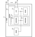
- FIG. 1 is a diagram illustrating an example of a framework for managing AI models.
- FIG. 2 is a diagram showing an example of specifying an AI model.
- FIG. 3 is a diagram showing an example of CSI feedback using an encoder/decoder.
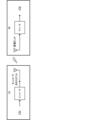
- FIG. 4 illustrates an example life cycle management framework for performance monitoring in a UE according to an embodiment.
- FIG. 5 illustrates an example life cycle management framework for performance monitoring in a BS according to one embodiment.
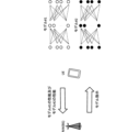
- 6A and 6B are diagrams showing an example of an AI-based beam report.
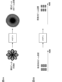
- FIG. 7 illustrates an example of performance monitoring of CSI compression at the UE side.
- FIG. 8 is a diagram showing an example of CSI reconstruction using a proxy model.
- FIG. 1 is a diagram illustrating an example of a framework for managing AI models.
- FIG. 2 is a diagram showing an example of specifying an AI model.
- FIG. 3 is a diagram showing an example of CSI feedback using an encoder/decoder.
- FIG. 4 illustrates
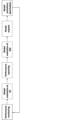
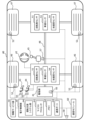
- FIG. 9 is a sequence diagram between a terminal (UE) and a base station (NW) showing an overall view of each embodiment of the present disclosure.
- FIG. 10 is a diagram showing association between RS resources for CSI reporting and RS resources for monitoring reporting.
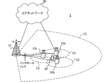
- FIG. 11 is a diagram illustrating an example of a schematic configuration of a wireless communication system according to an embodiment.
- FIG. 12 is a diagram illustrating an example of the configuration of a base station according to an embodiment.
- FIG. 13 is a diagram illustrating an example of the configuration of a user terminal according to an embodiment.
- FIG. 14 is a diagram illustrating an example of the hardware configuration of a base station and a user terminal according to an embodiment.
- FIG. 15 is a diagram illustrating an example of a vehicle according to an embodiment.
- the UE generates (also called determining, calculating, estimating, measuring, etc.) CSI based on a reference signal (RS) (or a resource for the RS) and transmits (also called reporting, feedback, etc.) the generated CSI to a network (e.g., a base station).
- RS reference signal
- the CSI may be transmitted to the base station using, for example, an uplink control channel (e.g., a Physical Uplink Control Channel (PUCCH)) or an uplink shared channel (e.g., a Physical Uplink Shared Channel (PUSCH)).
- PUCCH Physical Uplink Control Channel
- PUSCH Physical Uplink Shared Channel
- CSI includes a Channel Quality Indicator (CQI), a Precoding Matrix Indicator (PMI), a CSI-RS Resource Indicator (CRI), a SS/PBCH Block Resource Indicator (SSBRI), a Layer Indicator (LI), a Rank Indicator (RI), and a Layer 1 Reference Signal Received Power (L1-RSRP).
- CQI Channel Quality Indicator
- PMI Precoding Matrix Indicator
- CRI CSI-RS Resource Indicator
- SSBRI SS/PBCH Block Resource Indicator
- LI Layer Indicator
- RI Rank Indicator
- L1-RSRP Layer 1 Reference Signal Received Power
- L1-Reference Signal Received Power L1-RSRQ
- L1-SINR Signal to Interference plus Noise Ratio
- L1-SNR Signal to Noise Ratio
- information on the channel matrix or channel coefficients
- information on the precoding matrix or precoding coefficients
- information on the beam/Transmission Configuration Indication state TCI state/spatial relation, etc.
- the RS used to generate the CSI may be, for example, at least one of a Channel State Information Reference Signal (CSI-RS), a Synchronization Signal/Physical Broadcast Channel (SS/PBCH) block, a Synchronization Signal (SS), and a DeModulation Reference Signal (DMRS).
- CSI-RS Channel State Information Reference Signal
- SS/PBCH Synchronization Signal/Physical Broadcast Channel
- SS Synchronization Signal
- DMRS DeModulation Reference Signal
- RS Non Zero Power (NZP) CSI-RS, Zero Power (ZP) CSI-RS, CSI Interference Measurement (CSI-IM), CSI-SSB, and SSB
- NZP Non Zero Power
- ZP Zero Power
- CSI-IM CSI Interference Measurement
- CSI-SSB CSI Interference Measurement
- SSB SSB
- CSI-RS may include other reference signals.
- the UE may receive configuration information regarding CSI reporting (which may be referred to as CSI report configuration, report setting, etc.) and control CSI reporting based on the configuration information.
- the report configuration information may be, for example, a Radio Resource Control (RRC) Information Element (IE) "CSI-ReportConfig.”
- RRC Radio Resource Control
- IE Radio Resource Control Information Element
- the CSI reporting configuration may include at least one of the following information: Information regarding the CSI resources used for CSI measurements (resource configuration ID, for example, "CSI-ResourceConfigId”); Information regarding one or more quantities (CSI parameters) of CSI to be reported (report quantity information, e.g., "reportQuantity”); - Report type information (eg, "reportConfigType”) indicating the time domain behavior of the reporting configuration.
- resource configuration ID for example, "CSI-ResourceConfigId”
- Information regarding one or more quantities (CSI parameters) of CSI to be reported report quantity information, e.g., "reportQuantity”
- - Report type information eg, "reportConfigType" indicating the time domain behavior of the reporting configuration.
- a CSI resource may be interchangeably referred to as a time instance, a CSI-RS opportunity/CSI-IM opportunity/SSB opportunity, a CSI-RS resource (one/multiple) opportunity, a CSI opportunity, an opportunity, a CSI-RS resource/CSI-IM resource/SSB resource, a time resource, a frequency resource, an antenna port (e.g., a CSI-RS port), etc.
- the time unit of a CSI resource may be a slot, a symbol, etc.
- the information on the CSI resources may include information on CSI resources for channel measurement, information on CSI resources for interference measurement (NZP-CSI-RS resources), information on CSI-IM resources for interference measurement, etc.
- the reporting amount information may specify any one of the above CSI parameters (e.g., CRI, RI, PMI, CQI, LI, L1-RSRP, etc.) or a combination of these.
- CSI parameters e.g., CRI, RI, PMI, CQI, LI, L1-RSRP, etc.
- the report type information may indicate a periodic CSI (Periodic CSI (P-CSI)) report, an aperiodic CSI (A-CSI) report, or a semi-persistent CSI (Semi-Persistent CSI (SP-CSI)) report.
- P-CSI Period CSI
- A-CSI aperiodic CSI
- SP-CSI semi-persistent CSI
- the UE performs CSI-RS/SSB/CSI-IM measurements based on the CSI resource configuration corresponding to the CSI reporting configuration (the CSI resource configuration associated with CSI-ResourceConfigId) and derives the CSI to be reported based on the measurement results.
- the CSI resource configuration (e.g., the CSI-ResourceConfig information element) may include a csi-RS-ResourceSetList field indicating more specific CSI-RS/SSB resources, resource type information (e.g., "resourceType") indicating the time domain behavior of the resource configuration, etc.
- the resource type information may indicate a P-CSI resource, an A-CSI resource, or an SP-CSI resource.
- AI Artificial Intelligence
- ML machine learning
- CSI channel state information
- UE user equipment
- BS base stations
- CSI channel state information
- UE user equipment
- beam management e.g., improving accuracy, prediction in the time/space domain
- position measurement e.g., improving position estimation/prediction
- the AI model may output at least one piece of information such as an estimate, a prediction, a selected action, a classification, etc. based on the input information.
- the UE/BS may input channel state information, reference signal measurements, etc. to the AI model, and output highly accurate channel state information/measurements/beam selection/position, future channel state information/radio link quality, etc.
- AI may be interpreted as an object (also called a target, object, data, function, program, etc.) having (implementing) at least one of the following characteristics: - Estimation based on observed or collected information; - making choices based on observed or collected information; - Predictions based on observed or collected information.
- estimation, prediction, and inference may be interpreted as interchangeable. Also, in this disclosure, estimate, predict, and infer may be interpreted as interchangeable.
- an object may be, for example, an apparatus such as a UE or a BS, or a device. Also, in the present disclosure, an object may correspond to a program/model/entity that operates in the apparatus.
- an AI model may be interpreted as an object having (implementing) at least one of the following characteristics: - Producing estimates by feeding information, - Predicting estimates by providing information - Discover features by providing information, - Select an action by providing information.
- an AI model may refer to a data-driven algorithm that applies AI techniques to generate a set of outputs based on a set of inputs.
- AI model, model, ML model, predictive analytics, predictive analysis model, tool, autoencoder, encoder, decoder, neural network model, AI algorithm, scheme, etc. may be interchangeable.
- AI model may be derived using at least one of regression analysis (e.g., linear regression analysis, multiple regression analysis, logistic regression analysis), support vector machine, random forest, neural network, deep learning, etc.
- autoencoder may be interchangeably referred to as any autoencoder, such as a stacked autoencoder or a convolutional autoencoder.
- the encoder/decoder of this disclosure may employ models such as Residual Network (ResNet), DenseNet, and RefineNet.
- encoder encoding, encoding/encoded, modification/alteration/control by an encoder, compressing, compress/compressed, generating, generate/generated, etc. may be read as interchangeable terms.
- decoder decoding, decode/decoded, modification/alteration/control by a decoder, decompressing, decompress/decompressed, reconstructing, reconstruct/reconstructed, etc.
- decompressing decompress/decompressed, reconstructing, reconstruct/reconstructed, etc.
- a layer (of an AI model) may be interpreted as a layer (input layer, intermediate layer, etc.) used in an AI model.
- a layer in the present disclosure may correspond to at least one of an input layer, intermediate layer, output layer, batch normalization layer, convolution layer, activation layer, dense layer, normalization layer, pooling layer, attention layer, dropout layer, fully connected layer, etc.
- methods for training an AI model may include supervised learning, unsupervised learning, reinforcement learning, federated learning, and the like.
- Supervised learning may refer to the process of training a model from inputs and corresponding labels.
- Unsupervised learning may refer to the process of training a model without labeled data.
- Reinforcement learning may refer to the process of training a model from inputs (i.e., states) and feedback signals (i.e., rewards) resulting from the model's outputs (i.e., actions) in the environment with which the model interacts.
- terms such as generate, calculate, derive, etc. may be interchangeable.
- terms such as implement, operate, operate, execute, etc. may be interchangeable.
- terms such as train, learn, update, retrain, etc. may be interchangeable.
- terms such as infer, after-training, production use, actual use, etc. may be interchangeable.
- terms such as signal and signal/channel may be interchangeable.
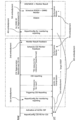
- FIG. 1 shows an example of a framework for managing an AI model.
- each stage related to the AI model is shown as a block.
- This example is also referred to as Life Cycle Management (LCM) of the AI model.
- LCM Life Cycle Management
- the data collection stage corresponds to the stage of collecting data for generating/updating an AI model.
- the data collection stage may include data organization (e.g., determining which data to transfer for model training/model inference), data transfer (e.g., transferring data to an entity (e.g., UE, gNB) that performs model training/model inference), etc.
- data collection may refer to a process in which data is collected by a network node, management entity, or UE for the purpose of AI model training/data analysis/inference.
- process and procedure may be interpreted as interchangeable.
- collection may also refer to obtaining a data set (e.g., usable as input/output) for training/inference of an AI model based on measurements (channel measurements, beam measurements, radio link quality measurements, position estimation, etc.).
- offline field data may be data collected from the field (real world) and used for offline training of an AI model.
- online field data may be data collected from the field (real world) and used for online training of an AI model.
- model training is performed based on the data (training data) transferred from the collection stage.
- This stage may include data preparation (e.g., performing data preprocessing, cleaning, formatting, conversion, etc.), model training/validation, model testing (e.g., checking whether the trained model meets performance thresholds), model exchange (e.g., transferring the model for distributed learning), model deployment/update (deploying/updating the model to the entities that will perform model inference), etc.
- AI model training may refer to a process for training an AI model in a data-driven manner and obtaining a trained AI model for inference.
- AI model validation may refer to a sub-process of training to evaluate the quality of an AI model using a dataset different from the dataset used to train the model. This sub-process helps select model parameters that generalize beyond the dataset used to train the model.
- AI model testing may refer to a sub-process of training to evaluate the performance of the final AI model using a dataset different from the dataset used for model training/validation. Note that testing, unlike validation, does not necessarily require subsequent model tuning.
- model inference is performed based on the data (inference data) transferred from the collection stage.
- This stage may include data preparation (e.g., performing data preprocessing, cleaning, formatting, transformation, etc.), model inference, model monitoring (e.g., monitoring the performance of model inference), model performance feedback (feeding back model performance to the entity performing the model training), output (providing model output to the actor), etc.
- AI model inference may refer to the process of using a trained AI model to produce a set of outputs from a set of inputs.
- a UE side model may refer to an AI model whose inference is performed entirely in the UE.
- a network side model may refer to an AI model whose inference is performed entirely in the network (e.g., gNB).
- a one-sided model may refer to a UE-side model or a network-side model.
- a two-sided model may refer to a pair of AI models where joint inference is performed.
- joint inference may include AI inference where the inference is performed jointly across the UE and the network, e.g., a first part of the inference may be performed first by the UE and the remaining part by the gNB (or vice versa).
- AI model monitoring may refer to the process of monitoring the inference performance of an AI model, and may be interpreted interchangeably as model performance monitoring, performance monitoring, etc.
- model registration may refer to making a model executable (registering) through assigning a version identifier to the model and compiling it into the specific hardware used in the inference stage.
- Model deployment may refer to distributing (or activating at) a fully developed and tested run-time image (or an image of the execution environment) of the model to the target (e.g., UE/gNB) where inference will be performed.
- Actor stages may include action triggers (e.g., deciding whether to trigger an action on another entity), feedback (e.g., feeding back information needed for training data/inference data/performance feedback), etc.
- action triggers e.g., deciding whether to trigger an action on another entity
- feedback e.g., feeding back information needed for training data/inference data/performance feedback
- training of a model for mobility optimization may be performed in, for example, Operation, Administration and Maintenance (Management) (OAM) in a network (NW)/gNodeB (gNB).
- OAM Operation, Administration and Maintenance
- NW network
- gNodeB gNodeB
- In the former case interoperability, large capacity storage, operator manageability, and model flexibility (feature engineering, etc.) are advantageous.
- the latency of model updates and the absence of data exchange for model deployment are advantageous.
- Inference of the above model may be performed in, for example, a gNB.
- the entity performing the training/inference may be different.
- the function of the AI model may include beam management, beam prediction, autoencoder (or information compression), CSI feedback, positioning, etc.
- the OAM/gNB may perform model training and the gNB may perform model inference.
- a Location Management Function may perform model training and the LMF may perform model inference.
- the OAM/gNB/UE may perform model training and the gNB/UE may perform model inference (jointly).
- the OAM/gNB/UE may perform model training and the UE may perform model inference.
- model activation may mean activating an AI model for a particular function.
- Model deactivation may mean disabling an AI model for a particular function.
- Model switching may mean deactivating a currently active AI model for a particular function and activating a different AI model.
- Model transfer may also refer to distributing an AI model over the air interface. This may include distributing either or both of the parameters of the model structure already known at the receiving end, or a new model with the parameters. This may also include a complete model or a partial model.
- Model download may refer to model transfer from the network to the UE.
- Model upload may refer to model transfer from the UE to the network.
- Figure 2 shows an example of specifying an AI model.
- the UE and NW e.g., a base station (BS)
- NW e.g., a base station (BS)
- the UE may report, for example, the capabilities of model #1 and model #2 to the NW, and the NW may instruct the UE on the AI model to use.
- AI-based CSI feedback As a use case of utilizing an AI model, CSI compression using a two-sided AI model is being considered. Such a CSI compression method may be called AI-based CSI feedback, and may be realized, for example, by using an autoencoder.
- Figure 3 shows an example of CSI feedback using an encoder/decoder.
- the UE transmits information (CSI feedback information) including encoded bits that are output by inputting CSI to an encoder from an antenna.
- the BS inputs the received CSI feedback information bits to a corresponding decoder to obtain the CSI to be output.
- the input CSI may include, for example, information on channel coefficients (elements of a channel matrix) or information on precoding coefficients (elements of a precoding matrix).
- the CSI may correspond to information on the channel state in the space-frequency domain.
- the input may include information other than CSI.
- the CSI output from the decoder may be reconstructed CSI that corresponds to the input to the encoder, or it may be CSI different from the input to the encoder (e.g., if the input information is information on channel coefficients, it may be information on precoding coefficients, etc.).
- the encoder/decoder may also include pre-processing of the input and post-processing of the output.
- the encoded bits are more compressed than the input information before encoding, which is expected to reduce the communication overhead required for CSI feedback.
- FIG. 4 illustrates an example of a lifecycle management framework for performance monitoring in a UE according to one embodiment.
- the UE monitors the performance of the model and fallback scheme (non-AI based CSI feedback).
- the UE evaluates the performance of the monitored/reported models and fallback schemes (non-AI based CSI feedback).
- the UE reports the above monitored performance to the NW.
- the NW evaluates the performance of the reported model and fallback scheme.
- the UE sends a request to the NW regarding which model should be applied or whether a fallback scheme should be applied.
- the UE may be instructed which scheme (model) is to be activated.
- the UE may activate a model or a fallback scheme.
- FIG. 5 illustrates an example of a life cycle management framework for performance monitoring in a BS according to one embodiment.
- the UE reports information for performance monitoring in the NW (BS).
- the network monitors the performance of the model and the fallback scheme (non-AI-based CSI feedback).
- the NW evaluates the performance of the model and the fallback scheme.
- the UE may be instructed which scheme (model) is to be activated.
- the UE may activate a model or a fallback scheme.
- AI-based beam report As a use case of utilizing the AI model, spatial domain downlink (DL) beam prediction or temporal DL beam prediction using a one-sided AI model in the UE or NW is being considered.
- DL spatial domain downlink
- BM Beam Management
- FIGS. 6A and 6B are diagrams showing an example of an AI-based beam report.
- FIG. 6A shows spatial domain DL beam prediction.
- the UE may measure a spatially sparse (or thick) beam, input the measurement results, etc., into an AI model, and output a predicted result of the beam quality of a spatially dense (or thin) beam.
- Figure 6B shows temporal DL beam prediction.
- the UE may measure the beam over time, input the measurement results, etc., to an AI model, and output the predicted beam quality of the future beam.
- spatial domain DL beam prediction may be referred to as BM case 1
- temporal DL beam prediction may be referred to as BM case 2.
- temporal DL beam prediction may be referred to as, for example, time domain CSI prediction.
- the beams/RS related to the output (prediction result) of the AI model may be referred to as set A.
- the beams/RS related to the input of the AI model may be referred to as set B.
- Candidates for input to the AI model for BM Case 1/2 include L1-RSRP (Layer 1 Reference Signal Received Power), assistance information (e.g., beam shape information, UE position/direction information, transmit beam usage information), Channel Impulse Response (CIR) information, and corresponding DL transmit/receive beam IDs.
- L1-RSRP Layer 1 Reference Signal Received Power
- assistance information e.g., beam shape information, UE position/direction information, transmit beam usage information
- CIR Channel Impulse Response
- Possible outputs of the AI model for BM Case 1 include the IDs of the top K (K is an integer) transmit/receive beams, the predicted L1-RSRP of these beams, the probability that each beam is in the top K, and the angles of these beams.
- the candidates for the output of the AI model in BM Case 2 include predicted beam failures.
- KPI Key performance indicators
- KPIs for evaluating the performance impact of AI/ML models: ⁇ Performance ⁇ Intermediate KPI, - Link-level and system-level performance, ⁇ Generalization performance, Over-the-air (overhead) - Assistance information overhead, - Data collection overhead, Model delivery/transfer overhead, - Signaling overhead associated with other AI/ML models; Inference complexity, Computational complexity of model inference: floating point operations (FLOPs (note that s is lowercase)) (this means the amount of floating point operations), - Computational complexity of pre- and post-processing, -Model complexity (number of parameters/data size (e.g.
- KPIs are merely examples and other KPIs may be added to the list (e.g. KPIs related to model training, use case specific KPIs that are considered for a given use case, etc.).
- KPIs related to performance may be called performance KPIs.
- a genie-aided beam may refer to a beam with the highest or top K metrics (e.g., values such as L1-RSRP/L1-SINR) among the beams actually measured.
- KPI-1 Difference from the L1-RSRP of the top 1 predicted beam. For example, the difference between the ideal L1-RSRP of the top 1 predicted beam and the ideal L1-RSRP of the top 1 genie-aided beam.
- KPI-2 Prediction accuracy (%) using top 1 and top K beams. This is shown, for example, in the following percentages: Top 1 (%): The percentage of top 1 genie-aided beams that are top 1 beams. Top K/1 (%): The percentage of the top 1 genie-aided beam that is one of the top K predicted beams. Top 1/K (%): The percentage of the top 1 predicted beam that is one of the top K genie-aided beams.
- KPI-3 Cumulative Distribution Function (CDF) of the difference between the top predicted beam and L1-RSRP. For example, the CDF of KPI-1.
- KPI-4 Beam prediction accuracy (%) taking into account the 1 dB margin of the top beam. For example, the percentage of the top genie-aided beams whose ideal L1-RSRP is within 1 dB of the ideal L1-RSRP of the top beam.
- KPI-5 Difference from predicted L1-RSRP. The difference between the L1-RSRP of the top 1/K (%) predicted beam and the ideal L1-RSRP of the same beam.
- L1-RSRP may be replaced with other values included in CSI (e.g., L1-SINR, etc.).
- the beam/RS associated with the output (prediction result) of the AI model may be referred to as set A.
- the beam/RS associated with the input of the AI model may be referred to as set B.
- Set B measurements Measurement of L1-RSRP of set B.
- the overhead is M.
- Predicting Set A Use the trained model to predict the L1-RSRP of Set A based on the measurement data of Set B. This has zero overhead.
- Measurement of Set A Measure the L1-RSRP of Set A as the L1-RSRP of the genie-aided beam. Let this overhead be N.
- Top 1 (and top 1/K(%)) measurement of set A Top 1 (and top 1/K(%)) L1-RSRP measurement of set A.
- the overhead is 1 (1/K).
- Performance monitoring Calculation of existing KPIs. This has zero overhead.
- the overhead when applying KPI-1 to KPI-4 is M+N, and the overhead when applying KPI-5 is M+1 (or 1/K). Therefore, the overhead of KPI-5 ⁇ the overhead of KPI-1 to KPI-4.
- a method of reporting a monitored result (which may be called a monitored result) is considered.
- the UE may be configured to report a monitored result only as shown in at least one of Alt0 to Alt3 below.
- the UE may be configured with a different reporting configuration for monitoring result reporting than for CSI reporting.
- the CSI report and the monitoring result report may be associated with each other.
- at least one of the following settings Alt1 to Alt3 may be applied to the UE.
- Alt1 to Alt3 may be applied, for example, in the case of periodic/semi-persistent reporting, but are not limited thereto, and may also be applied to other cases.
- a number of resource settings may be associated with a CSI reporting configuration.
- two or more resource settings for channel measurements may be associated with a CSI reporting setting.
- one resource setting may correspond to either an RS resource for input (RS resource for input) or an RS resource for reference (RS resource for reference).
- Multiple CSI-RS resource sets may be associated with a CSI reporting setting.
- one CSI-RS resource set may correspond to either RS resources for input (input RS resources) or RS resources for reference (reference RS resources).
- Multiple CSI-RS resources (selected) from one CSI-RS resource set may be associated with a CSI reporting setting.
- one CSI-RS resource set may include RS resources for input (input RS resources) and RS resources for reference (reference RS resources).
- the slot offset between the input RS resource and the reference RS resource may be set/indicated or may be determined based on UE capabilities/predefined rules.
- the UE may trigger a monitoring result report. If a CSI report is associated with the monitoring result report, the UE may be configured with at least one of Alt4 to Alt7 below.
- One CSI-RS resource set (selected) from one resource setting may be associated with each trigger condition.
- one CSI-RS resource set may include RS resources for input (input RS resources) and RS resources for reference (reference RS resources).
- the input RS resource and the reference RS resource may be scheduled in different slots. This allows the input RS resource and the reference RS resource to have different timing offsets (slot offsets).
- the RS triggering offset may be configured for each RS resource or for one RS resource set (eg, including multiple RS resources).
- the slot offset between the input RS resource and the reference RS resource may be configured/indicated or may be determined based on UE capability/predefined rules.
- CSI-RS resource sets (selected from one resource setting) may be associated with each trigger condition.
- one CSI-RS resource set may correspond to either the input RS resources or the reference RS resources. This allows the input RS resources and the reference RS resources to have different timing offsets (slot offsets).
- One or more CSI-RS resource sets may be associated with each trigger condition.
- one resource setting may correspond to either the input RS resource or the reference RS resource. This allows the input RS resource and the reference RS resource to have different timing offsets (slot offsets).
- Different trigger conditions may be set to trigger the RS resources for aperiodic model input (model input RS resources) and the reference RS resources.
- the monitor result report trigger can be associated with any trigger condition.
- the above-mentioned reference resource may be a CSI-RS/DMRS that is beamformed after the CSI report.
- the above-mentioned CSI report and the monitor result report (monitoring report) may be physically separated and logically associated.
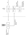
- Figure 7 shows an example of performance monitoring of CSI compression at the UE side.
- the UE may monitor the expected performance.
- the performance (expected performance) monitored in FIG. 7 may be at least one of the following: (1) Expected communication quality calculated based on the output of an AI model. For example, expected CQI that satisfies a certain block error probability under a specific resource allocation assumption. (2) The expected performance of the reconstructed CSI compared to the target CSI (e.g., expected noise variance).
- the CQI in (1) may be, for example, at least one of a wideband CQI, an average of subband CQIs, a weighted average of subband CQIs, a maximum/minimum of subband CQI, etc.
- the specific resource allocation may correspond to a frequency/time resource allocation for receiving a certain channel/signal (e.g., PDSCH, PDCCH, corresponding DMRS), and the type of resource allocation may be specified in the standard (e.g., the expected number of symbols, the number of resource blocks, etc.).
- the certain block error probability may be, for example, at least one of 0.1, 0.00001, etc.
- the CSI output from the decoder is the reconstructed CSI that corresponds to the input to the encoder.
- the decoder in the UE is only provided for performance monitoring, and the CSI feedback sent by the UE is the output of the encoder.
- the UE does not have a decoder that corresponds to the encoder.
- the UE performs channel measurements based on the CSI-RS transmitted from the BS and obtains the channel matrix H.
- the UE estimates its performance based on H.
- the UE may perform a specific process on H (e.g., Singular Value Decomposition (SVD)) to obtain W.
- H e.g., Singular Value Decomposition (SVD)
- the UE estimates performance based on W.
- the UE may perform the above-mentioned preprocessing on the above-mentioned W to obtain p-W.
- the UE may estimate performance based on p-W, or may estimate performance based on W.
- the UE may also transmit a performance report to the BS as necessary.
- the UE may receive information on the expected performance of the AI model corresponding to the encoder's AI model from the vendor's data server or NW.
- the information may be included in the AI model information.
- the data server may be interchangeably referred to as a repository, an uploader, a library, a cloud server, or simply a server.
- the data server in this disclosure may be provided by any platform such as GitHub (registered trademark), and may be operated by any company/organization.
- the UE performs channel measurement based on the CSI-RS transmitted from the BS, and obtains the H/W/p-W corresponding to the target CSI.
- the UE also calculates (estimates) the expected performance based on the target CSI and the above-mentioned expected performance information. If performance monitoring is the only task, the UE does not need to operate the encoder.
- the UE can use a proxy model to calculate the expected reconstructed CSI instead of the reconstructed model actually used by the base station.
- the proxy model is a model that mimics the reconstructed model used by the base station.
- the proxy model can be a simple model. This can reduce the processing and storage problems of the UE.
- the proxy model can be different from the actual reconstructed model in the base station. This can avoid the uniqueness problem.
- Figure 8 shows an example of CSI reconstruction (pseudo reconstruction) using a proxy model.
- the UE receives a proxy model for decoding from the NW (base station).
- the UE uses the proxy model to reconstruct the encoded CSI and outputs it as an estimated CSI.
- the UE maps the estimated result to the actual CSI and calculates a KPI (Key Performance Indicator) (e.g., SGCS (squared generalized cosine similarity)).
- KPI Key Performance Indicator
- SGCS squared generalized cosine similarity
- AI/ML-based CSI feedback is important for improving downlink transmission efficiency, and its performance should be monitored in real time.
- the NW/UE can switch models or revert to the existing framework (e.g., UE-side performance monitoring using the proxy model described above) to reduce link outages and throughput loss.
- the existing framework e.g., UE-side performance monitoring using the proxy model described above
- UE-side performance monitoring is one of the candidates for realizing real-time monitoring.
- the UE performs performance monitoring using beamformed CSI-RS (reconfigured and then beamformed CSI-RS).
- the UE also uses DMRS (beamformed DMRS with reported PMI) for performance monitoring to reduce CSI-RS overhead when certain conditions are met (e.g., in the case of SU-MIMO transmission).
- DMRS beamformed DMRS with reported PMI
- the UE has information on the undistorted (more accurate) target CSI, and can quickly identify model performance degradation.
- the proxy model may mean a model that is used only for performance monitoring and has no other uses than performance monitoring.
- the proxy model may mean a model that estimates secondary information (CQI/RI, etc.) of the restored CSI.
- the proxy model needs to be configured as a simple model because it has no other uses than performance monitoring. Therefore, there may be limitations on the complexity of the UE side in terms of implementing the proxy model.
- the inventors have come up with an extended method for improving the accuracy of monitoring on the UE side.
- A/B and “at least one of A and B” may be interpreted as interchangeable. Also, in this disclosure, “A/B/C” may mean “at least one of A, B, and C.”
- Radio Resource Control RRC
- RRC parameters RRC parameters
- RRC messages higher layer parameters, fields, information elements (IEs), settings, etc.
- IEs information elements
- CE Medium Access Control
- update commands activation/deactivation commands, etc.
- the higher layer signaling may be, for example, any one of Radio Resource Control (RRC) signaling, Medium Access Control (MAC) signaling, broadcast information, other messages (e.g., messages from the core network such as positioning protocols (e.g., NR Positioning Protocol A (NRPPa)/LTE Positioning Protocol (LPP)) messages), or a combination of these.
- RRC Radio Resource Control
- MAC Medium Access Control
- LPP LTE Positioning Protocol
- the MAC signaling may use, for example, a MAC Control Element (MAC CE), a MAC Protocol Data Unit (PDU), etc.
- the broadcast information may be, for example, a Master Information Block (MIB), a System Information Block (SIB), Remaining Minimum System Information (RMSI), Other System Information (OSI), etc.
- MIB Master Information Block
- SIB System Information Block
- RMSI Remaining Minimum System Information
- OSI System Information
- the physical layer signaling may be, for example, Downlink Control Information (DCI), Uplink Control Information (UCI), etc.
- DCI Downlink Control Information
- UCI Uplink Control Information
- index identifier
- indicator indicator
- resource ID etc.
- sequence list, set, group, cluster, subset, etc.
- TRP
- CSI-RS Non-Zero Power (NZP) CSI-RS, Zero Power (ZP) CSI-RS, and CSI Interference Measurement (CSI-IM) may be interchangeable.
- CSI-RS may include other reference signals.
- the measured/reported RS may refer to the RS measured/reported for CSI reporting.
- timing, time, duration, slot, subslot, symbol, subframe, etc. may be interpreted as interchangeable.
- direction, axis, dimension, domain, polarization, polarization component, etc. may be interpreted as interchangeable.
- estimation, prediction, and inference may be interpreted as interchangeable. Also, in this disclosure, estimate, predict, and infer may be interpreted as interchangeable.
- the autoencoder, encoder, decoder, etc. may be interpreted as at least one of a model, an ML model, a neural network model, an AI model, an AI algorithm, etc.
- the autoencoder may be interpreted as any autoencoder, such as a stacked autoencoder or a convolutional autoencoder.
- the encoder/decoder of the present disclosure may employ models such as Residual Network (ResNet), DenseNet, and RefineNet.
- bits, bit strings, bit series, series, values, information, values obtained from bits, information obtained from bits, etc. may be interpreted as interchangeable.
- a layer for an encoder
- a layer may be interchangeably read as a layer (input layer, intermediate layer, etc.) used in an AI model.
- a layer in the present disclosure may correspond to at least one of an input layer, intermediate layer, output layer, batch normalization layer, convolution layer, activation layer, dense layer, normalization layer, pooling layer, attention layer, dropout layer, fully connected layer, etc.
- RSRP may be interchangeably read as any parameter related to reception power/reception quality, etc. (e.g., RSRQ, SINR, CSI, etc.).
- the RS may be, for example, a CSI-RS, an SS/PBCH block (SS block (SSB)), etc.
- the RS index may be a CSI-RS resource indicator (CSI-RS Resource Indicator (CRI)), an SS/PBCH block resource indicator (SS/PBCH Block Indicator (SSBRI)), etc.
- CSI-RS Resource Indicator CRI
- SSBRI SS/PBCH Block Indicator
- channel measurement/estimation may be performed using at least one of, for example, a Channel State Information Reference Signal (CSI-RS), a Synchronization Signal (SS), a Synchronization Signal/Physical Broadcast Channel (SS/PBCH) block, a DeModulation Reference Signal (DMRS), a Sounding Reference Signal (SRS), etc.
- CSI-RS Channel State Information Reference Signal
- SS Synchronization Signal
- SS/PBCH Synchronization Signal/Physical Broadcast Channel
- DMRS DeModulation Reference Signal
- SRS Sounding Reference Signal
- the terms receive beam assumption, number of receive beams, receive beam index, receive beam selection, receive beam setting, and receive beam instruction may be interchangeable.
- the terms receive beam, transmit beam, DL receive beam, DL transmit beam, and transmit and receive beam pairs may be interchangeable.
- transmit/receive beam may be interchangeable with transmit/receive beams for beam prediction, and transmit/receive beams for CSI measurement/reporting for beam prediction.
- functionality may refer to the use of a model or the physical meaning of the model's input/output. Multiple models may have the same functionality. Monitoring (checking performance)/activation/deactivation/switching/fallback/update may be instructed (controlled) based on the functionality (e.g., for each function).
- a model ID may also refer to an identifier for a model (or a set of models). Multiple models may be assigned the same model ID in an actual deployment. In this case, these models may actually be different models (e.g., have different number of layers, etc.), but may be treated as the same model.
- the use cases may include AI/ML for at least one of enhanced CSI feedback/beam management/enhanced positioning.
- the use cases may also include other new use cases for AI/ML.
- the model ID may be interchangeably read as a meta information (or a set of meta information) ID.
- the meta information (or meta information ID) may be associated with information regarding the applicability of the model/functionality, the environment, the UE/gNB settings, etc.
- functionality, function, functionality ID, model, and model ID may be interpreted interchangeably.
- update, report, and send may be read interchangeably.
- meta information may be interpreted as interchangeable.
- monitor and evaluation may be interpreted interchangeably.
- entity specific entity, UE, NW, gNB, and LMF may be read as interchangeable.
- NW may be interpreted as interchangeable.
- the UE side model and UE may be interpreted as interchangeable.
- model UE side model
- logical model logical model
- physical model may be interchangeable.
- model/functionality may refer to a data-driven algorithm that applies AI/ML techniques to generate a set of outputs based on a set of inputs.
- performance indicators and monitoring indicators may be interpreted as interchangeable.
- association, correspondence, and mapping may be interpreted as interchangeable.
- monitor result monitored result
- post-monitoring result post-monitoring result
- monitoring result may be read interchangeably.
- the monitoring results may include information regarding at least one of the inference results, a performance index, and the content of an event occurrence based on the performance index/whether or not an event has occurred.
- the UE may report the following information as monitoring results: Performance metrics corresponding to the monitored model/functionality.
- Performance metrics corresponding to the monitored model/functionality.
- An event occurs in the calculation of a performance index corresponding to a monitored model/functionality (eg, the value of a positive index is greater/less than a threshold for a certain duration).
- AI/ML-based CSI reporting may refer to a CSI report associated with a model ID or specific functionality, where the specific functionality may be, for example, at least one of predicted CSI, compressed CSI, advanced CSI, and type [x] CSI.
- AI/ML-based CSI reporting and CSI reporting may be read interchangeably.
- a proxy model may refer to a model that is used only for performance monitoring and has no other uses other than performance monitoring.
- a proxy model may refer to a model that estimates secondary information (CQI/RI, etc.) of the restored CSI.
- AI/ML functionality, AI/ML CSI functionality may refer to functionality commanded by the NW or reported by the UE, such as at least one of predicted CSI, compressed CSI, advanced CSI, and type [x] CSI.
- AI/ML functionality, AI/ML CSI functionality, and functionality may be read interchangeably.
- an AI/ML model an AI/ML CSI model may refer to a model/entity that is identified by a specific ID and performs a specific function (functionality).
- report quantity information regarding report quantity, and report quantity information may be read interchangeably.
- reporting settings may be read interchangeably.
- report CSI report, measurement result report, monitoring report, and monitor result report may be read interchangeably.
- CSI-RS and PDSCH/DMRS may be interpreted as interchangeable.
- type X monitoring may refer to monitoring (results) based on precoded RS resources.
- type Y monitoring may refer to monitoring (results) based on PDSCH/DMRS.
- RS Type B may refer to an RS (signal/channel) associated with a measurement report/monitoring result report
- RS Type A may refer to an RS (signal/channel) associated with a CSI report associated with a model ID or specific functionality/feature.
- performance metrics metrics for monitoring reports, and KPIs may be interpreted interchangeably.
- the embodiments of the present disclosure can be broadly classified as follows.
- First embodiment Reporting configuration for CSI-RS based monitoring.
- Second embodiment Triggering of CSI-RS transmission and monitoring reports.
- Third embodiment Relationship between CSI reports and monitoring reports.
- Fourth embodiment Reporting configuration for PDSCH/DMRS based monitoring.
- Fifth embodiment Triggering of aperiodic CSI-RS transmission and monitoring reports.
- Sixth embodiment Relationship between CSI reports and monitoring reports.
- Seventh embodiment UE behavior in performance monitoring based on new performance indicators (KPIs).
- Eighth embodiment UE behavior regarding monitoring of layer mapping with rank adaptation. Each embodiment will be described below based on these.
- FIG. 9 is a sequence diagram between a terminal (UE) and a base station (NW) showing an overall picture of each embodiment of the present disclosure.
- the procedure shown in FIG. 9 is merely an example, and the order of each step can be changed as appropriate as long as no contradiction occurs.
- first the network sends reporting settings for CSI reporting to the UE.
- the network sends activation of CSI feedback (CSF) to the UE.
- CSF CSI feedback
- the NW transmits a reporting configuration for monitoring reports to the UE (first embodiment).
- the reporting configuration for CSI reports and the reporting configuration for monitoring reports are associated with each other (third embodiment).
- the network sends a CSI report trigger (trigger instruction) to the UE.
- the network transmits input RS resources (RS type A) to the UE.
- the UE performs CSI compression based on the input RS resources.
- the UE performs (sends) a CSI report to the network.
- the network performs CSI registration and beamforming of the CSI-RS.
- the network transmits reference RS resources (RS type B) to the UE.
- RS type B reference RS resources
- the UE performs performance monitoring.
- the network performs scheduling for CSI monitoring feedback.
- the UE transmits a monitoring result report (monitoring report) to the NW (second embodiment). In other words, the UE feeds back the monitoring result to the NW.
- the NW transmits a reporting configuration for monitoring reports to the UE (fourth embodiment).
- the reporting configuration for CSI reports and the reporting configuration for monitoring reports are associated with each other (sixth embodiment).
- the network performs SU-MIMO beamforming on the reconstructed CSI.
- the network transmits PDSCH/DMRS to the UE.
- the network schedules (triggers) monitoring reports for PDSCH/DMRS (fifth embodiment).
- the UE sends ACK/NACK and monitoring results (monitoring report) to the NW.
- each embodiment/option may be applied alone or in combination with multiple options.
- the first embodiment relates to monitoring based on the CSI framework, and in particular describes report configuration.
- the CSI-RS may be a precoded/beamformed CSI-RS.
- the UE may be configured in the CSI-RS to monitor the performance of AI/ML-based CSI reporting (i.e., CSI reporting performance monitoring) by at least one of the following options.
- the configuration regarding CSI reporting performance monitoring may be referred to as monitor reporting configuration.
- Option 1-1 relates to a configuration based on the CSI framework.
- the UE may be configured for performance monitoring of CSI reports by the CSI report configuration (CSI-ReportConfig) received from the NW via higher layer signaling/physical layer signaling.
- CSI-ReportConfig the CSI report configuration
- the CSI reporting configuration may include at least type X monitoring results within information (report quantity information, e.g., "reportQuantity" in the RRC IE) regarding one or more quantities of CSI to be reported (one or more CSI parameters).
- report quantity information e.g., "reportQuantity" in the RRC IE
- the type X monitoring result may refer to a monitoring result based on precoded RS resources.
- the reporting amount for type X monitoring results may be a gap (measurement gap) of RSRP/SINR/CQI.
- the reporting amount is a gap of RSRP
- the UE may be configured with only CSI resources for channel measurement, not including resources for interference measurement, in the CSI reporting configuration.
- Options 1-2 relate to configurations based on frameworks other than the CSI framework (e.g., the LCM framework in Rel. 19 and later).
- the UE may be configured to monitor the performance of CSI reports by specific signaling received from the network via higher layer signaling/physical layer signaling.
- the specified signaling may include a CSI resource set index or a CSI resource index for the monitoring result of type X.
- the specified signaling may be dedicated signaling or signaling for purposes other than CSI reporting (e.g., signaling for model/functionality activation, signaling for model switching, etc.).
- the resources for monitoring need to be different from the resources for CSI compression and CSI feedback.
- the resources for CSI compression and CSI feedback may be configured by separate signaling corresponding to CSI reporting.
- the UE may expect the above signaling to include an indication of the model/functionality and an index to the model/functionality (Model ID/Functionality ID).
- the UE may also expect the above signaling to include monitor reporting configuration, which may include instructions regarding the periodicity and resources for monitor reporting.
- the UE may treat the RS resources configured in Options 1-1 to 1-2 described above as RS type B.
- the UE may expect the configured CSI reporting to be periodic/semi-persistent/aperiodic.
- RS Type B may refer to an RS (signal/channel) associated with a measurement report/monitor result report.
- the UE can properly recognize the reporting settings for monitoring based on CSI-RS.
- the second embodiment relates to monitoring based on the CSI framework, in particular the triggering of CSI-RS transmission and monitoring reports.
- the UE may be triggered to perform monitoring reporting based on the existing CSI framework, i.e., RRC (e.g., CSI-AperiodicTriggerStatelist)/MAC CE/DCI or RRC (e.g., CSI-SemiPersistentOnPUSCH-TriggerStatelist)/DCI may be used to trigger monitoring reporting.
- RRC e.g., CSI-AperiodicTriggerStatelist
- MAC CE/DCI e.g., CSI-SemiPersistentOnPUSCH-TriggerStatelist
- DCI CSI-SemiPersistentOnPUSCH-TriggerStatelist
- the UE may be triggered to report type X monitoring results by higher layer signaling/physical layer signaling.
- the UE may also expect the RS resource ID/report ID to be configured/indicated by higher layer/physical layer signaling.
- the RS resource ID/report ID may correspond to the ID configured for type X monitoring.
- Performance monitoring allows for fewer trigger states required for reporting, since individual signaling (e.g., dedicated signaling, such as a new DCI) requires less overhead than CSI framework signaling.
- the UE may be configured with a new parameter (monitoring-TriggerStatelist) consisting of N (N ⁇ 16) trigger states, where each trigger state in the monitoring-TriggerStatelist may include M resource IDs/report IDs.
- monitoring-TriggerStatelist consisting of N (N ⁇ 16) trigger states, where each trigger state in the monitoring-TriggerStatelist may include M resource IDs/report IDs.
- the UE may decide whether to use existing parameters (CSI-AperiodicTriggerStatelist/CSI-SemiPersistentOnPUSCH-TriggerStatelist) or other (new) parameters (monitoring-TriggerStatelist) based on the detected triggering DCI (triggering DCI).
- existing parameters CSI-AperiodicTriggerStatelist/CSI-SemiPersistentOnPUSCH-TriggerStatelist
- new parameters monitoring-TriggerStatelist
- the UE may use a new parameter (monitoring-TriggerStatelist).
- the triggering DCI may add a new field, for example, 1 bit, to an existing DCI, and use the new field to indicate whether the DCI is for a CSI report or a monitoring report.
- the UE may use the existing parameters (CSI-AperiodicTriggerStatelist/CSI-SemiPersistentOnPUSCH-TriggerStatelist).
- the UE can appropriately control the triggering of monitoring reports based on the CSI-RS.
- the third embodiment relates to monitoring based on a CSI framework, and in particular describes a relationship (association) between an RS resource for a CSI report and an RS resource for a monitoring report.
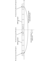
- Figure 10 is a diagram showing an association between an RS resource for a CSI report and an RS resource for a monitoring report.
- the UE associates the RS type B with the RS type A signal/channel (hereinafter simply referred to as RS type A) received in slot T'.
- the UE then derives the monitoring result using the pair (which may be referred to as an RS pair) of the two associated signals/channels (RS type A and RS type B).
- slot T' may be a slot a predetermined period before slot T (a predetermined slot: 9 slots in FIG. 10).
- RS type A may mean an RS (signal/channel) related to a CSI report associated with a model ID or a specific functionality/characteristic.
- the CSI report may be, for example, a CSI report for predicted CSI or compressed CSI.
- the RS resource of RS type A may be read as an input RS resource.
- the UE may determine the above-mentioned slot T' according to at least one of Alt3-1 to Alt3-2 below. That is, slot T' may be any of the slots shown in Alt3-1 to Alt3-2 below.
- ⁇ Alt3-1> The slot in which RS Type A is transmitted and is used for the latest AI/ML-based CSI reporting.
- the slot is a slot in which RS type A is transmitted before the slot T-k and is used for the latest AI/ML-based CSI report (slot T′′ in FIG. 10).
- k may be set/indicated in higher layer signaling/physical layer signaling, or may be predefined by a specification.
- the UE may associate RS type B with RS type A and ignore the input RS resources used by other models, where the other models may be models (different from AI/ML CSI functionality/models) that are not associated with RS type A.
- the UE can appropriately distinguish between CSI reports and monitoring reports based on the type of RS resource.
- the fourth embodiment relates to monitoring based on PDSCH/DMRS, and in particular describes report configuration.
- the UE may be configured to monitor the performance of AI/ML-based CSI reporting (i.e., CSI reporting performance monitoring) in PDSCH/DMRS resources scheduled as RS type B by at least one of the following options:
- the UE may be configured for CSI reporting performance monitoring by the CSI report configuration (CSI-ReportConfig) received from the NW via higher layer signaling/physical layer signaling.
- the higher layer signaling/physical layer signaling may configure/indicate the measurement resources of the PDSCH/DMRS scheduled for the UE.
- the CSI reporting configuration may include at least type X/Y monitoring results within information (report quantity information, e.g., "reportQuantity" in the RRC IE) regarding one or more quantities of CSI to be reported (one or more CSI parameters).
- report quantity information e.g., "reportQuantity" in the RRC IE
- the type Y monitoring result may mean a monitoring result based on PDSCH/DMRS. Also, the type Y monitoring may be the same as the type X monitoring.
- the reporting amount for type X/Y monitoring results may be the RSRP/SINR/CQI gap (measurement gap).
- the UE may be configured to monitor the performance of CSI reports by specific signaling received from the network via higher layer signaling/physical layer signaling.
- the specified signaling may include settings/instructions for monitoring PDSCH/DMRS.
- the specified signaling may be dedicated signaling or signaling for purposes other than CSI reporting (e.g., signaling for LCM of AI/ML-based CSI reporting, signaling for model/functionality activation for AI/ML-based CSI reporting, signaling for model switching, etc.).
- the UE may expect the above signaling to include an indication of the model/functionality and an index to the model/functionality (Model ID/Functionality ID).
- the UE may also expect the above signaling to include monitor reporting configuration, which may include instructions regarding the periodicity and resources for monitor reporting.
- monitoring of PDSCH/DMRS may be opportunistic based on scheduling and conditions (e.g., SU-MIMO transmission, latency).
- the gNB itself may determine whether PDSCH/DMRS is a suitable opportunity for monitoring and notify the UE.
- the report type may be periodic/semi-persistent/non-periodic, and the following may be exemplified:
- the corresponding PDSCH/DMRS may be set by the index of the semi-persistent scheduling (SPS) PDSCH.
- SPS semi-persistent scheduling
- the corresponding PDSCH/DMRS may be determined based on the time offset between the PDSCH/DMRS and the PUCCH/PUSCH for reporting.
- the time offset may be indicated by DCI triggering in case of semi-persistent reporting, or set by RRC in case of periodic/aperiodic reporting.
- the corresponding PDSCH/DMRS may be determined as (based on) the latest PDSCH reception at least X symbols/slots prior to the reporting PUCCH/PUSCH.
- the corresponding PDSCH/DMRS may be determined as (based on) the configured/indicated antenna port.
- the PDSCH/DMRS scheduled at antenna port 1000 may be utilized.
- the corresponding PDSCH/DMRS may be determined as (based on) the configured/indicated HARQ process number.
- the UE can properly recognize the monitoring report settings based on the PDSCH/DMRS.
- the fifth embodiment relates to triggering of monitoring reports based on PDSCH/DMRS.
- the UE may be triggered to report type Y monitoring results by higher layer signaling/physical layer signaling.
- the UE may report type Y monitoring results using higher layer signaling/physical layer signaling when at least one of the following conditions 5-1 to 5-4 is satisfied.
- Reporting of type Y monitoring results is configured/indicated by higher layer/physical layer signaling, which may be the same as the signaling that schedules the PDSCH or may be different signaling.
- Condition 5-1 AND Condition 5-2 In this case, the condition is satisfied only when both conditions 5-1 and 5-2 are satisfied.
- condition 5-1 has a higher priority than condition 5-3.
- condition 5-1 with the higher priority is given priority. In other words, whether the condition is met or not may depend on the outcome of the condition 5-1.
- the UE can appropriately control the triggering of monitoring reports based on PDSCH/DMRS.
- the sixth embodiment relates to monitoring based on PDSCH/DMRS, and in particular describes the relationship (association) between RS resources for CSI reporting and RS resources for monitoring reporting. Note that the sixth embodiment can be applied by replacing the CSI-RS in the third embodiment with PDSCH/DMRS. That is, the contents of FIG. 10 can also be applied to the following description.
- a UE when a UE receives RS type B in a certain time slot T, the UE associates RS type B with RS type A received in slot T'. Then, the UE derives the monitoring result using a pair (which may be called an RS pair) of the two associated signals/channels (RS type A and RS type B).
- a pair which may be called an RS pair
- slot T' may be a slot a predetermined period before slot T (a predetermined slot: 9 slots in FIG. 10).
- RS type A may refer to an RS (signal/channel) related to a CSI report associated with a model ID or a specific functionality/characteristic.
- the CSI report may be, for example, a CSI report for predicted CSI or compressed CSI.
- the UE may determine the above-mentioned slot T' according to at least one of Alt6-1 to Alt6-2 below. That is, slot T' may be any of the slots shown in Alt6-1 to Alt6-2 below.
- ⁇ Alt6-1> The slot in which RS Type A is transmitted and is used for the latest AI/ML-based CSI reporting.
- the slot is a slot in which RS type A is transmitted before the slot T-k and is used for the latest AI/ML-based CSI report (slot T′′ in FIG. 10).
- k may be set/indicated in higher layer signaling/physical layer signaling, or may be predefined by a specification.
- the UE may associate RS type B with RS type A and ignore the input RS resources used by other models, where the other models may be models (different from AI/ML CSI functionality/models) that are not associated with RS type A.
- the UE can appropriately distinguish between CSI reports and monitoring reports based on the type of RS resource.
- the seventh embodiment relates to UE operation in performance monitoring based on a new performance indicator.
- Aspect 7-1 relates to a new performance index.
- the UE may be configured/instructed by higher layer signaling/physical layer signaling of the performance indicators for performance monitoring and the corresponding values.
- the UE may have the performance indicators for performance monitoring and the corresponding values determined by the specifications.
- the performance indicators and the corresponding values may be at least one of the following options 7-1 to 7-3.
- Absolute value of measured RSRP/SINR/CQI Absolute value for measured value:. This absolute value may be referred to as an absolute threshold metric value.
- Target RSRP/SINR/CQI Relative offset value (difference between target and measured values) expressed in measured RSRP/SINR/CQI.
- the difference value may be called a relative offset metric value.
- the target values (target RSRP/SINR/CQI) may be derived based on configured/indicated parameters or predefined rules.
- Aspect 7-2 relates to UE operation of performance monitoring based on a novel performance indicator.
- the UE may monitor the performance of the AI/ML-based CSI report based on a pair of two signals/channels (RS type A and RS type B) associated with each other (may be called an RS pair). The procedure is described below.
- the UE calculates target values (target RSRP/SINR/CQI) based on RS type A.
- ⁇ Step 2> The UE measures the measurements (measured RSRP/SINR/CQI) based on RS type B.
- the UE may derive the monitoring result based on the above performance indicators and their corresponding values (eg, RS pairs).
- the UE can appropriately control monitoring reports based on the new performance indicators.
- An eighth embodiment describes UE operation with respect to monitoring layer mapping with rank adaptation.
- the UE may perform the following operations:
- the UE may monitor the layer (number) corresponding to the smallest value (number) of the port/layer number and rank indicator.
- the UE may assume that the port/layer order is the same between the precoding matrix indicator (PMI) in the AI/ML-based CSI report and RS type B.
- the UE may be configured/instructed on the port/layer order by higher layer/physical layer signaling, which may include a bit indicating the layer mapping.
- the UE can appropriately control the UE operation related to monitoring the layer (mapping) based on the rank indicator.
- AI model information may mean information including at least one of the following: ⁇ Information on input/output of AI model. - Pre-processing/post-processing information for input/output of AI models. ⁇ Information on AI model parameters. - Training information for AI models. -Inference information for AI models. ⁇ Performance information about the AI model.
- the input/output information of the AI model may include information regarding at least one of the following: Input/output data content (e.g. RSRP, SINR, amplitude/phase information in the channel matrix (or precoding matrix), information on the Angle of Arrival (AoA), information on the Angle of Departure (AoD), location information).
- Input/output data content e.g. RSRP, SINR, amplitude/phase information in the channel matrix (or precoding matrix), information on the Angle of Arrival (AoA), information on the Angle of Departure (AoD), location information).
- Supporting information for the data may be called meta-information).
- the type of input/output data e.g. immutable values, floating point numbers).
- the bit width of the input/output data eg, 64 bits for each input value).
- Quantization interval (quantization step size) of input/output data eg, 1 dBm for L1-RSRP).
- the information regarding AoA may include information regarding at least one of the azimuth angle of arrival and the zenith angle of arrival (ZoA). Furthermore, the information regarding AoD may include information regarding at least one of the azimuth angle of departure and the zenith angle of departure (ZoD), for example.
- the location information may be location information regarding the UE/NW.
- the location information may include at least one of information (e.g., latitude, longitude, altitude) obtained using a positioning system (e.g., a satellite positioning system (Global Navigation Satellite System (GNSS), Global Positioning System (GPS), etc.)), information on the BS adjacent to (or serving) the UE (e.g., a BS/cell identifier (ID), a BS-UE distance, a direction/angle of the BS (UE) as seen from the UE (BS), coordinates of the BS (UE) as seen from the UE (BS) (e.g., coordinates on the X/Y/Z axes), etc.), a specific address of the UE (e.g., an Internet Protocol (IP) address), etc.
- IP Internet Protocol
- the location information of the UE is not limited to information based on the position of the BS, and may be information based on a specific point.
- the location information may include information about its implementation (e.g., location/position/orientation of antennas, location/orientation of antenna panels, number of antennas, number of antenna panels, etc.).
- the location information may include mobility information.
- the mobility information may include information indicating at least one of the following: information indicating a mobility type, a moving speed of the UE, an acceleration of the UE, a moving direction of the UE, etc.
- the mobility type may correspond to at least one of fixed location UE, movable/moving UE, no mobility UE, low mobility UE, middle mobility UE, high mobility UE, cell-edge UE, not-cell-edge UE, etc.
- environmental information may be information regarding the environment in which the data is acquired/used, and may correspond to, for example, frequency information (such as a band ID), environmental type information (information indicating at least one of indoor, outdoor, Urban Macro (UMa), Urban Micro (Umi), etc.), information indicating Line Of Site (LOS)/Non-Line Of Site (NLOS), etc.
- frequency information such as a band ID
- environmental type information information indicating at least one of indoor, outdoor, Urban Macro (UMa), Urban Micro (Umi), etc.
- LOS Line Of Site
- NLOS Non-Line Of Site
- LOS may mean that the UE and BS are in an environment where they can see each other (or there is no obstruction)
- NLOS may mean that the UE and BS are not in an environment where they can see each other (or there is an obstruction).
- Information indicating LOS/NLOS may indicate a soft value (e.g., the probability of LOS/NLOS) or a hard value (e.g., either LOS or NLOS).
- meta-information may mean, for example, information regarding input/output information suitable for an AI model, information regarding data that has been acquired/can be acquired, etc.
- meta-information may include information regarding beams of RS (e.g., CSI-RS/SRS/SSB, etc.) (e.g., the pointing angle of each beam, 3 dB beam width, the shape of the pointed beam, the number of beams), gNB/UE antenna layout information, frequency information, environmental information, meta-information ID, etc.
- RS e.g., CSI-RS/SRS/SSB, etc.
- gNB/UE antenna layout information e.g., the pointing angle of each beam, 3 dB beam width, the shape of the pointed beam, the number of beams
- meta-information may be used as input/output of an AI model.
- the pre-processing/post-processing information for the input/output of the AI model may include information regarding at least one of the following: Whether to apply normalization (e.g., Z-score normalization, min-max normalization). Parameters for normalization (eg, mean/variance for Z-score normalization, min/max for min-max normalization). Whether to apply a specific numeric transformation method (e.g., one hot encoding, label encoding, etc.). Selection rule for whether or not to use as training data.
- normalization e.g., Z-score normalization, min-max normalization
- Parameters for normalization eg, mean/variance for Z-score normalization, min/max for min-max normalization
- a specific numeric transformation method e.g., one hot encoding, label encoding, etc.
- the information of the parameters of the AI model may include information regarding at least one of the following: - Weight information (e.g., neuron coefficients (connection coefficients)) in an AI model. ⁇ Structure of the AI model. - The type of AI model as a model component (e.g., Residual Network (ResNet), DenseNet, RefineNet, Transformer model, CRBlock, Recurrent Neural Network (RNN), Long Short-Term Memory (LSTM), Gated Recurrent Unit (GRU)). - Functions of the AI model as model components (e.g., decoder, encoder).
- ResNet Residual Network
- DenseNet DenseNet
- RefineNet Transformer model
- CRBlock Recurrent Neural Network
- RNN Recurrent Neural Network
- LSTM Long Short-Term Memory
- GRU Gated Recurrent Unit
- the weight information in the AI model may include information regarding at least one of the following: - Bit width (size) of the weight information. Quantization interval of weight information. - Granularity of weight information. - The range of possible weight information. ⁇ Weight parameters in AI models. - Information on the difference from the AI model before the update (if updating). - Method of weight initialization (e.g., zero initialization, random initialization (based on normal/uniform/truncated normal distribution), Xavier initialization (for sigmoid function), He initialization (for Rectified Linear Units (ReLU))).
- the structure of the AI model may also include information regarding at least one of the following: ⁇ Number of layers. - The type of layer (e.g., convolutional, activation, dense, normalization, pooling, attention). ⁇ Layer information. Time series specific parameters (e.g. bidirectionality, time step). Parameters for training (e.g., type of feature (L2 regularization, dropout feature, etc.), where to put this feature (e.g., after which layer)).
- ⁇ Number of layers e.g., convolutional, activation, dense, normalization, pooling, attention.
- ⁇ Layer information Time series specific parameters (e.g. bidirectionality, time step).
- Parameters for training e.g., type of feature (L2 regularization, dropout feature, etc.), where to put this feature (e.g., after which layer)).
- the layer information may include information regarding at least one of the following: - The number of neurons in each layer. ⁇ Kernel size. - Stride for pooling/convolutional layers. -Pooling method (MaxPooling, AveragePooling, etc.). ⁇ Residual block information. ⁇ Number of heads. - Normalization method (batch normalization, instance normalization, layer normalization, etc.). Activation functions (sigmoid, tanh function, ReLU, leaky ReLU information, Maxout, Softmax).
- An AI model may be included as a component of another AI model.
- an AI model may be an AI model in which processing proceeds in the order of model component #1 (ResNet), model component #2 (a transformer model), a dense layer, and a normalization layer.
- ResNet model component #1
- model component #2 a transformer model
- dense layer a dense layer
- normalization layer a normalization layer
- Training information for the AI model may include information regarding at least one of the following: Information for the optimization algorithm (e.g. type of optimization (Stochastic Gradient Descent (SGD)), AdaGrad, Adam, etc.), parameters of the optimization (learning rate, momentum information, etc.). Loss function information (e.g., information on the metrics of the loss function (Mean Absolute Error (MAE)), Mean Square Error (MSE)), Cross Entropy Loss, NLL Loss, Kullback-Leibler (KL) Divergence, etc.)).
- - Parameters to be frozen for training e.g. layers, weights
- - Parameters to be updated e.g. layers, weights
- Parameters e.g. layers, weights
- Parameters that should be (are used as) initial parameters for training. How to train/update the AI model (e.g., (recommended) number of epochs, batch size, number of data used for training).
- the inference information for the AI model may include information regarding decision tree branch pruning, parameter quantization, and the function of the AI model.
- the function of the AI model may correspond to at least one of, for example, time domain beam prediction, spatial domain beam prediction, autoencoder for CSI feedback, and autoencoder for beam management.
- An autoencoder for CSI feedback may be used as follows: - The UE inputs the CSI/channel matrix/precoding matrix into the AI model of the encoder and transmits the encoded bits output as CSI feedback (CSI report). - The BS reconstructs the CSI/channel matrix/precoding matrix, which is output as input to the AI model of the decoder using the received encoded bits.
- the UE/BS may input measurement results (beam quality, e.g., RSRP) based on sparse (or thick) beams into an AI model to output dense (or thin) beam quality.
- beam quality e.g., RSRP
- the UE/BS may input time series (past, present, etc.) measurement results (beam quality, e.g., RSRP) into an AI model and output future beam quality.
- time series past, present, etc.
- beam quality e.g., RSRP
- the performance information regarding the AI model may include information regarding the expected value of a loss function defined for the AI model.
- the AI model information in this disclosure may include information regarding the scope of application (scope of applicability) of the AI model.
- the scope of application may be indicated by a physical cell ID, a serving cell index, etc.
- Information regarding the scope of application may be included in the above-mentioned environmental information.
- AI model information regarding a specific AI model may be predetermined in a standard, or may be notified to the UE from the network (NW).
- An AI model defined in a standard may be referred to as a reference AI model.
- AI model information regarding a reference AI model may be referred to as reference AI model information.
- the AI model information in the present disclosure may include an index for identifying the AI model (e.g., may be called an AI model index, an AI model ID, a model ID, etc.).
- the AI model information in the present disclosure may include an AI model index in addition to/instead of the input/output information of the AI model described above.
- the association between the AI model index and the AI model information (e.g., input/output information of the AI model) may be predetermined in a standard, or may be notified to the UE from the NW.
- the AI model information in this disclosure may be associated with an AI model and may be referred to as AI model relevant information, simply relevant information, etc.
- the AI model relevant information does not need to explicitly include information for identifying the AI model.
- the AI model relevant information may be information that includes only meta information, for example.
- the model ID may be interchangeably read as an ID (model set ID) corresponding to a set of AI models.
- the model ID may be interchangeably read as a meta information ID.
- the meta information (or meta information ID) may be associated with information regarding the beam (beam setting) as described above.
- the meta information (or meta information ID) may be used by the UE to select an AI model taking into account which beam the BS is using, or may be used to notify the BS of which beam to use to apply the AI model deployed by the UE.
- the meta information ID may be interchangeably read as an ID (meta information set ID) corresponding to a set of meta information.
- any information may be notified to the UE (from the NW) (in other words, any information received from the BS in the UE) using physical layer signaling (e.g., DCI), higher layer signaling (e.g., RRC signaling, MAC CE), a specific signal/channel (e.g., PDCCH, PDSCH, reference signal), or a combination thereof.
- physical layer signaling e.g., DCI
- higher layer signaling e.g., RRC signaling, MAC CE
- a specific signal/channel e.g., PDCCH, PDSCH, reference signal
- the MAC CE may be identified by including a new Logical Channel ID (LCID) in the MAC subheader that is not specified in existing standards.
- LCID Logical Channel ID
- the notification may be made by a specific field of the DCI, a Radio Network Temporary Identifier (RNTI) used to scramble Cyclic Redundancy Check (CRC) bits assigned to the DCI, the format of the DCI, etc.
- RNTI Radio Network Temporary Identifier
- CRC Cyclic Redundancy Check
- notification of any information to the UE in the above-mentioned embodiments may be performed periodically, semi-persistently, or aperiodically.
- notification of any information from the UE may be performed using physical layer signaling (e.g., UCI), higher layer signaling (e.g., RRC signaling, MAC CE), a specific signal/channel (e.g., PUCCH, PUSCH, reference signal), or a combination thereof.
- physical layer signaling e.g., UCI
- higher layer signaling e.g., RRC signaling, MAC CE
- a specific signal/channel e.g., PUCCH, PUSCH, reference signal
- the MAC CE may be identified by including a new LCID in the MAC subheader that is not specified in existing standards.
- the notification may be transmitted using PUCCH or PUSCH.
- notification of any information from the UE may be performed periodically, semi-persistently, or aperiodically.
- At least one of the above-mentioned embodiments may be applied when a specific condition is satisfied, which may be specified in a standard or may be notified to a UE/BS using higher layer signaling/physical layer signaling.
- At least one of the above-described embodiments may be applied only to UEs that have reported or support certain UE capabilities, for example, as described below (by way of example only): - Supporting specific processing/operations/control/information for at least one of the above embodiments.
- Support performance monitoring (reporting) based on the CSI framework.
- Support performance monitoring (reporting) based on PDSCH/DMRS.
- the particular UE capability may indicate support for particular processing/operations/control/information for at least one of the above embodiments/options/options.
- the above-mentioned specific UE capabilities may be capabilities that are applied across all frequencies (commonly regardless of frequency), capabilities per frequency (e.g., one or a combination of a cell, band, band combination, BWP, component carrier, etc.), capabilities per frequency range (e.g., Frequency Range 1 (FR1), FR2, FR3, FR4, FR5, FR2-1, FR2-2), capabilities per subcarrier spacing (SubCarrier Spacing (SCS)), or capabilities per Feature Set (FS) or Feature Set Per Component-carrier (FSPC).
- FR1 Frequency Range 1
- FR2 FR2, FR3, FR4, FR5, FR2-1, FR2-2
- SCS subcarrier Spacing
- FS Feature Set
- FSPC Feature Set Per Component-carrier
- the specific UE capabilities may be capabilities that are applied across all duplexing methods (commonly regardless of the duplexing method), or may be capabilities for each duplexing method (e.g., Time Division Duplex (TDD) and Frequency Division Duplex (FDD)).
- TDD Time Division Duplex
- FDD Frequency Division Duplex
- the above-mentioned embodiments may be applied when the UE configures/activates/triggers specific information related to the above-mentioned embodiments (or performs the operations of the above-mentioned embodiments) by higher layer signaling/physical layer signaling.
- the specific information may be information indicating the activation of LCM based on a model/functionality ID, any RRC parameters for a specific release (e.g., Rel. 18/19), etc.
- the UE may apply, for example, the behavior of Rel. 15/16/17.
- a terminal comprising: a control unit that controls performance monitoring of artificial intelligence (AI)-based channel state information (CSI) reporting based on the reporting configuration.
- AI artificial intelligence
- CSI channel state information
- the control unit performs the performance monitoring in the resource of the PDSCH or the DMRS, The terminal of claim 1, wherein the reporting configuration includes a monitoring result of type X or type Y based on the PDSCH or the DMRS.
- a terminal comprising: a control unit that controls performance monitoring of artificial intelligence (AI) based channel state information (CSI) reports based on the performance indicator.
- the control unit derives a monitoring result based on an absolute value for a measurement value of a certain channel or a reference signal (RS), or a difference value between the measurement value and a target value for the measurement value.
- RS reference signal
- Wired communication system A configuration of a wireless communication system according to an embodiment of the present disclosure will be described below.
- communication is performed using any one of the wireless communication methods according to the above embodiments of the present disclosure or a combination of these.
- FIG. 11 is a diagram showing an example of a schematic configuration of a wireless communication system according to an embodiment.
- the wireless communication system 1 (which may simply be referred to as system 1) may be a system that realizes communication using Long Term Evolution (LTE) specified by the Third Generation Partnership Project (3GPP), 5th generation mobile communication system New Radio (5G NR), or the like.
- LTE Long Term Evolution
- 3GPP Third Generation Partnership Project
- 5G NR 5th generation mobile communication system New Radio
- the wireless communication system 1 may also support dual connectivity between multiple Radio Access Technologies (RATs) (Multi-RAT Dual Connectivity (MR-DC)).
- MR-DC may include dual connectivity between LTE (Evolved Universal Terrestrial Radio Access (E-UTRA)) and NR (E-UTRA-NR Dual Connectivity (EN-DC)), dual connectivity between NR and LTE (NR-E-UTRA Dual Connectivity (NE-DC)), etc.
- RATs Radio Access Technologies
- MR-DC may include dual connectivity between LTE (Evolved Universal Terrestrial Radio Access (E-UTRA)) and NR (E-UTRA-NR Dual Connectivity (EN-DC)), dual connectivity between NR and LTE (NR-E-UTRA Dual Connectivity (NE-DC)), etc.
- E-UTRA Evolved Universal Terrestrial Radio Access
- EN-DC E-UTRA-NR Dual Connectivity
- NE-DC NR-E-UTRA Dual Connectivity
- the wireless communication system 1 may support dual connectivity between multiple base stations within the same RAT (e.g., dual connectivity in which both the MN and SN are NR base stations (gNBs) (NR-NR Dual Connectivity (NN-DC))).
- dual connectivity in which both the MN and SN are NR base stations (gNBs) (NR-NR Dual Connectivity (NN-DC))).
- gNBs NR base stations
- N-DC Dual Connectivity
- the wireless communication system 1 may include a base station 11 that forms a macrocell C1 with a relatively wide coverage, and base stations 12 (12a-12c) that are arranged within the macrocell C1 and form a small cell C2 that is narrower than the macrocell C1.
- a user terminal 20 may be located within at least one of the cells. The arrangement and number of each cell and user terminal 20 are not limited to the embodiment shown in the figure. Hereinafter, when there is no need to distinguish between the base stations 11 and 12, they will be collectively referred to as base station 10.
- the user terminal 20 may be connected to at least one of the multiple base stations 10.
- the user terminal 20 may utilize at least one of carrier aggregation (CA) using multiple component carriers (CC) and dual connectivity (DC).
- CA carrier aggregation
- CC component carriers
- DC dual connectivity
- Each CC may be included in at least one of a first frequency band (Frequency Range 1 (FR1)) and a second frequency band (Frequency Range 2 (FR2)).
- Macro cell C1 may be included in FR1
- small cell C2 may be included in FR2.
- FR1 may be a frequency band below 6 GHz (sub-6 GHz)
- FR2 may be a frequency band above 24 GHz (above-24 GHz). Note that the frequency bands and definitions of FR1 and FR2 are not limited to these, and for example, FR1 may correspond to a higher frequency band than FR2.
- the user terminal 20 may communicate using at least one of Time Division Duplex (TDD) and Frequency Division Duplex (FDD) in each CC.
- TDD Time Division Duplex
- FDD Frequency Division Duplex
- the multiple base stations 10 may be connected by wire (e.g., optical fiber conforming to the Common Public Radio Interface (CPRI), X2 interface, etc.) or wirelessly (e.g., NR communication).
- wire e.g., optical fiber conforming to the Common Public Radio Interface (CPRI), X2 interface, etc.
- NR communication e.g., NR communication
- base station 11 which corresponds to the upper station
- IAB Integrated Access Backhaul
- base station 12 which corresponds to a relay station
- the base station 10 may be connected to the core network 30 via another base station 10 or directly.
- the core network 30 may include, for example, at least one of an Evolved Packet Core (EPC), a 5G Core Network (5GCN), a Next Generation Core (NGC), etc.
- EPC Evolved Packet Core
- 5GCN 5G Core Network
- NGC Next Generation Core
- the core network 30 may include network functions (Network Functions (NF)) such as, for example, a User Plane Function (UPF), an Access and Mobility management Function (AMF), a Session Management Function (SMF), a Unified Data Management (UDM), an Application Function (AF), a Data Network (DN), a Location Management Function (LMF), and Operation, Administration and Maintenance (Management) (OAM).
- NF Network Functions
- UPF User Plane Function
- AMF Access and Mobility management Function
- SMF Session Management Function
- UDM Unified Data Management
- AF Application Function
- DN Data Network
- LMF Location Management Function
- OAM Operation, Administration and Maintenance
- the user terminal 20 may be a terminal that supports at least one of the communication methods such as LTE, LTE-A, and 5G.
- a wireless access method based on Orthogonal Frequency Division Multiplexing may be used.
- OFDM Orthogonal Frequency Division Multiplexing
- CP-OFDM Cyclic Prefix OFDM
- DFT-s-OFDM Discrete Fourier Transform Spread OFDM
- OFDMA Orthogonal Frequency Division Multiple Access
- SC-FDMA Single Carrier Frequency Division Multiple Access
- the radio access method may also be called a waveform.
- other radio access methods e.g., other single-carrier transmission methods, other multi-carrier transmission methods
- a downlink shared channel (Physical Downlink Shared Channel (PDSCH)) shared by each user terminal 20, a broadcast channel (Physical Broadcast Channel (PBCH)), a downlink control channel (Physical Downlink Control Channel (PDCCH)), etc. may be used as the downlink channel.
- PDSCH Physical Downlink Shared Channel
- PBCH Physical Broadcast Channel
- PDCCH Physical Downlink Control Channel
- an uplink shared channel (Physical Uplink Shared Channel (PUSCH)) shared by each user terminal 20, an uplink control channel (Physical Uplink Control Channel (PUCCH)), a random access channel (Physical Random Access Channel (PRACH)), etc. may be used as an uplink channel.
- PUSCH Physical Uplink Shared Channel
- PUCCH Physical Uplink Control Channel
- PRACH Physical Random Access Channel
- Lower layer control information may be transmitted by the PDCCH.
- the lower layer control information may include, for example, downlink control information (Downlink Control Information (DCI)) including scheduling information for at least one of the PDSCH and the PUSCH.
- DCI Downlink Control Information
- the DCI for scheduling the PDSCH may be called a DL assignment or DL DCI
- the DCI for scheduling the PUSCH may be called a UL grant or UL DCI.
- the PDSCH may be interpreted as DL data
- the PUSCH may be interpreted as UL data.
- a control resource set (COntrol REsource SET (CORESET)) and a search space may be used to detect the PDCCH.
- the CORESET corresponds to the resources to search for DCI.
- the search space corresponds to the search region and search method of PDCCH candidates.
- One CORESET may be associated with one or multiple search spaces. The UE may monitor the CORESET associated with a certain search space based on the search space configuration.
- a search space may correspond to PDCCH candidates corresponding to one or more aggregation levels.
- One or more search spaces may be referred to as a search space set. Note that the terms “search space,” “search space set,” “search space setting,” “search space set setting,” “CORESET,” “CORESET setting,” etc. in this disclosure may be read as interchangeable.
- the PUCCH may transmit uplink control information (UCI) including at least one of channel state information (CSI), delivery confirmation information (which may be called, for example, Hybrid Automatic Repeat reQuest ACKnowledgement (HARQ-ACK), ACK/NACK, etc.), and a scheduling request (SR).
- UCI uplink control information
- CSI channel state information
- HARQ-ACK Hybrid Automatic Repeat reQuest ACKnowledgement
- ACK/NACK ACK/NACK
- SR scheduling request
- the PRACH may transmit a random access preamble for establishing a connection with a cell.
- downlink, uplink, etc. may be expressed without adding "link.”
- various channels may be expressed without adding "Physical” to the beginning.
- a synchronization signal (SS), a downlink reference signal (DL-RS), etc. may be transmitted.
- a cell-specific reference signal (CRS), a channel state information reference signal (CSI-RS), a demodulation reference signal (DMRS), a positioning reference signal (PRS), a phase tracking reference signal (PTRS), etc. may be transmitted.
- this example mainly shows the functional blocks of the characteristic parts of this embodiment, and the base station 10 may also be assumed to have other functional blocks necessary for wireless communication. Some of the processing of each part described below may be omitted.
- the control unit 110 may control signal generation, scheduling (e.g., resource allocation, mapping), etc.
- the control unit 110 may control transmission and reception using the transceiver unit 120, the transceiver antenna 130, and the transmission path interface 140, measurement, etc.
- the control unit 110 may generate data, control information, sequences, etc. to be transmitted as signals, and transfer them to the transceiver unit 120.
- the control unit 110 may perform call processing of communication channels (setting, release, etc.), status management of the base station 10, management of radio resources, etc.
- the transceiver unit 120 may include a baseband unit 121, a radio frequency (RF) unit 122, and a measurement unit 123.
- the baseband unit 121 may include a transmission processing unit 1211 and a reception processing unit 1212.
- the transceiver unit 120 may be composed of a transmitter/receiver, an RF circuit, a baseband circuit, a filter, a phase shifter, a measurement circuit, a transceiver circuit, etc., which are described based on a common understanding in the technical field to which the present disclosure relates.
- the transceiver unit 120 may be configured as an integrated transceiver unit, or may be composed of a transmission unit and a reception unit.
- the transmission unit may be composed of a transmission processing unit 1211 and an RF unit 122.
- the reception unit may be composed of a reception processing unit 1212, an RF unit 122, and a measurement unit 123.
- the transmitting/receiving antenna 130 can be configured as an antenna described based on common understanding in the technical field to which this disclosure pertains, such as an array antenna.
- the transceiver 120 may transmit the above-mentioned downlink channel, synchronization signal, downlink reference signal, etc.
- the transceiver 120 may receive the above-mentioned uplink channel, uplink reference signal, etc.
- the transceiver unit 120 may form at least one of the transmit beam and the receive beam using digital beamforming (e.g., precoding), analog beamforming (e.g., phase rotation), etc.
- digital beamforming e.g., precoding
- analog beamforming e.g., phase rotation
- the transceiver 120 may perform Packet Data Convergence Protocol (PDCP) layer processing, Radio Link Control (RLC) layer processing (e.g., RLC retransmission control), Medium Access Control (MAC) layer processing (e.g., HARQ retransmission control), etc. on data and control information obtained from the control unit 110 to generate a bit string to be transmitted.
- PDCP Packet Data Convergence Protocol
- RLC Radio Link Control
- MAC Medium Access Control
- HARQ retransmission control HARQ retransmission control
- the transceiver unit 120 may perform transmission processing such as channel coding (which may include error correction coding), modulation, mapping, filtering, Discrete Fourier Transform (DFT) processing (if necessary), Inverse Fast Fourier Transform (IFFT) processing, precoding, and digital-to-analog conversion on the bit string to be transmitted, and output a baseband signal.
- transmission processing such as channel coding (which may include error correction coding), modulation, mapping, filtering, Discrete Fourier Transform (DFT) processing (if necessary), Inverse Fast Fourier Transform (IFFT) processing, precoding, and digital-to-analog conversion on the bit string to be transmitted, and output a baseband signal.
- channel coding which may include error correction coding
- DFT Discrete Fourier Transform
- IFFT Inverse Fast Fourier Transform
- the transceiver unit 120 may perform modulation, filtering, amplification, etc., on the baseband signal to a radio frequency band, and transmit the radio frequency band signal via the transceiver antenna 130.
- the transceiver unit 120 may perform amplification, filtering, demodulation to a baseband signal, etc. on the radio frequency band signal received by the transceiver antenna 130.
- the transceiver 120 may apply reception processing such as analog-to-digital conversion, Fast Fourier Transform (FFT) processing, Inverse Discrete Fourier Transform (IDFT) processing (if necessary), filtering, demapping, demodulation, decoding (which may include error correction decoding), MAC layer processing, RLC layer processing, and PDCP layer processing to the acquired baseband signal, and acquire user data, etc.
- reception processing such as analog-to-digital conversion, Fast Fourier Transform (FFT) processing, Inverse Discrete Fourier Transform (IDFT) processing (if necessary), filtering, demapping, demodulation, decoding (which may include error correction decoding), MAC layer processing, RLC layer processing, and PDCP layer processing to the acquired baseband signal, and acquire user data, etc.
- FFT Fast Fourier Transform
- IDFT Inverse Discrete Fourier Transform
- the transceiver 120 may perform measurements on the received signal.
- the measurement unit 123 may perform Radio Resource Management (RRM) measurements, Channel State Information (CSI) measurements, etc. based on the received signal.
- the measurement unit 123 may measure received power (e.g., Reference Signal Received Power (RSRP)), received quality (e.g., Reference Signal Received Quality (RSRQ), Signal to Interference plus Noise Ratio (SINR), Signal to Noise Ratio (SNR)), signal strength (e.g., Received Signal Strength Indicator (RSSI)), propagation path information (e.g., CSI), etc.
- RSRP Reference Signal Received Power
- RSSI Received Signal Strength Indicator
- the measurement results may be output to the control unit 110.
- the transmission path interface 140 may transmit and receive signals (backhaul signaling) between devices included in the core network 30 (e.g., network nodes providing NF), other base stations 10, etc., and may acquire and transmit user data (user plane data), control plane data, etc. for the user terminal 20.
- devices included in the core network 30 e.g., network nodes providing NF
- other base stations 10, etc. may acquire and transmit user data (user plane data), control plane data, etc. for the user terminal 20.
- the transmitting unit and receiving unit of the base station 10 in this disclosure may be configured by at least one of the transmitting/receiving unit 120, the transmitting/receiving antenna 130, and the transmission path interface 140.
- the transceiver 120 may transmit a report configuration for performance monitoring based on a downlink shared channel (PDSCH) or a demodulation reference signal (DMRS).
- the control unit 110 may control performance monitoring of artificial intelligence (AI)-based channel state information (CSI) reports based on the report configuration.
- AI artificial intelligence
- CSI channel state information
- the transceiver 120 may transmit a performance indicator for performance monitoring of an artificial intelligence (AI)-based channel state information (CSI) report.
- the controller 110 may control the performance monitoring of the artificial intelligence (AI)-based channel state information (CSI) report based on the performance indicator.
- the user terminal 20 includes a control unit 210, a transceiver unit 220, and a transceiver antenna 230. Note that the control unit 210, the transceiver unit 220, and the transceiver antenna 230 may each include one or more.
- this example mainly shows the functional blocks of the characteristic parts of this embodiment, and the user terminal 20 may also be assumed to have other functional blocks necessary for wireless communication. Some of the processing of each part described below may be omitted.
- the control unit 210 controls the entire user terminal 20.
- the control unit 210 can be configured from a controller, a control circuit, etc., which are described based on a common understanding in the technical field to which this disclosure pertains.
- the control unit 210 may control signal generation, mapping, etc.
- the control unit 210 may control transmission and reception using the transceiver unit 220 and the transceiver antenna 230, measurement, etc.
- the control unit 210 may generate data, control information, sequences, etc. to be transmitted as signals, and transfer them to the transceiver unit 220.
- the transceiver unit 220 may include a baseband unit 221, an RF unit 222, and a measurement unit 223.
- the baseband unit 221 may include a transmission processing unit 2211 and a reception processing unit 2212.
- the transceiver unit 220 may be composed of a transmitter/receiver, an RF circuit, a baseband circuit, a filter, a phase shifter, a measurement circuit, a transceiver circuit, etc., which are described based on a common understanding in the technical field to which the present disclosure relates.
- the transceiver unit 220 may be configured as an integrated transceiver unit, or may be composed of a transmission unit and a reception unit.
- the transmission unit may be composed of a transmission processing unit 2211 and an RF unit 222.
- the reception unit may be composed of a reception processing unit 2212, an RF unit 222, and a measurement unit 223.
- the transmitting/receiving antenna 230 can be configured as an antenna described based on common understanding in the technical field to which this disclosure pertains, such as an array antenna.
- the transceiver 220 may receive the above-mentioned downlink channel, synchronization signal, downlink reference signal, etc.
- the transceiver 220 may transmit the above-mentioned uplink channel, uplink reference signal, etc.
- the transceiver 220 may perform PDCP layer processing, RLC layer processing (e.g., RLC retransmission control), MAC layer processing (e.g., HARQ retransmission control), etc. on the data and control information acquired from the controller 210, and generate a bit string to be transmitted.
- RLC layer processing e.g., RLC retransmission control
- MAC layer processing e.g., HARQ retransmission control
- the transceiver 220 may perform transmission processing such as channel coding (which may include error correction coding), modulation, mapping, filtering, DFT processing (if necessary), IFFT processing, precoding, and digital-to-analog conversion on the bit string to be transmitted, and output a baseband signal.
- transmission processing such as channel coding (which may include error correction coding), modulation, mapping, filtering, DFT processing (if necessary), IFFT processing, precoding, and digital-to-analog conversion on the bit string to be transmitted, and output a baseband signal.
- Whether or not to apply DFT processing may be based on the settings of transform precoding.
- the transceiver unit 220 transmission processing unit 2211
- the transceiver unit 220 may perform DFT processing as the above-mentioned transmission processing in order to transmit the channel using a DFT-s-OFDM waveform, and when transform precoding is not enabled, it is not necessary to perform DFT processing as the above-mentioned transmission processing.
- the transceiver unit 220 may perform modulation, filtering, amplification, etc., on the baseband signal to a radio frequency band, and transmit the radio frequency band signal via the transceiver antenna 230.
- the transceiver unit 220 may perform amplification, filtering, demodulation to a baseband signal, etc. on the radio frequency band signal received by the transceiver antenna 230.
- the transceiver 220 may apply reception processing such as analog-to-digital conversion, FFT processing, IDFT processing (if necessary), filtering, demapping, demodulation, decoding (which may include error correction decoding), MAC layer processing, RLC layer processing, and PDCP layer processing to the acquired baseband signal to acquire user data, etc.
- reception processing such as analog-to-digital conversion, FFT processing, IDFT processing (if necessary), filtering, demapping, demodulation, decoding (which may include error correction decoding), MAC layer processing, RLC layer processing, and PDCP layer processing to the acquired baseband signal to acquire user data, etc.
- the transceiver 220 may perform measurements on the received signal. For example, the measurement unit 223 may perform RRM measurements, CSI measurements, etc. based on the received signal.
- the measurement unit 223 may measure received power (e.g., RSRP), received quality (e.g., RSRQ, SINR, SNR), signal strength (e.g., RSSI), propagation path information (e.g., CSI), etc.
- the measurement results may be output to the control unit 210.
- the measurement unit 223 may derive channel measurements for CSI calculation based on channel measurement resources.
- the channel measurement resources may be, for example, non-zero power (NZP) CSI-RS resources.
- the measurement unit 223 may derive interference measurements for CSI calculation based on interference measurement resources.
- the interference measurement resources may be at least one of NZP CSI-RS resources for interference measurement, CSI-Interference Measurement (IM) resources, etc.
- CSI-IM may be called CSI-Interference Management (IM) or may be interchangeably read as Zero Power (ZP) CSI-RS.
- CSI-RS, NZP CSI-RS, ZP CSI-RS, CSI-IM, CSI-SSB, etc. may be read as interchangeable.
- the transmitting unit and receiving unit of the user terminal 20 in this disclosure may be configured by at least one of the transmitting/receiving unit 220 and the transmitting/receiving antenna 230.
- the transceiver 220 may receive a report configuration for performance monitoring based on a downlink shared channel (PDSCH) or a demodulation reference signal (DMRS).
- the controller 210 may control performance monitoring of an artificial intelligence (AI)-based channel state information (CSI) report based on the report configuration.
- the controller 210 may execute the performance monitoring in the PDSCH or DMRS resource.
- the report configuration may include a type X or type Y monitoring result based on the PDSCH or the DMRS.
- the controller 210 may trigger a report of the monitoring result based on the type Y monitoring result based on the PDSCH or the DMRS included in the report configuration.
- the controller 210 may derive the monitoring result based on an association between an RS resource of RS type A and an RS resource of RS type B.
- the transceiver 220 may receive a performance indicator for performance monitoring of an artificial intelligence (AI)-based channel state information (CSI) report.
- the controller 210 may control the performance monitoring of the artificial intelligence (AI)-based channel state information (CSI) report based on the performance indicator.
- the controller 210 may derive a monitoring result based on an absolute value for a measurement value of a channel or reference signal (RS), or a difference value between a target value for the measurement value and the measurement value.
- the controller 210 may control the measurement value based on an RS resource of RS type A, an RS resource of RS type B, or an association between the RS type A and the RS type B.
- the controller 210 may control the AI-based CSI report based on RS type A with a rank indicator.
- each functional block may be realized using one device that is physically or logically coupled, or may be realized using two or more devices that are physically or logically separated and directly or indirectly connected (for example, using wires, wirelessly, etc.).
- the functional blocks may be realized by combining the one device or the multiple devices with software.
- the functions include, but are not limited to, judgement, determination, judgment, calculation, computation, processing, derivation, investigation, search, confirmation, reception, transmission, output, access, resolution, selection, selection, establishment, comparison, assumption, expectation, deeming, broadcasting, notifying, communicating, forwarding, configuring, reconfiguring, allocating, mapping, and assignment.
- a functional block (component) that performs the transmission function may be called a transmitting unit, a transmitter, and the like. In either case, as mentioned above, there are no particular limitations on the method of realization.
- a base station, a user terminal, etc. in one embodiment of the present disclosure may function as a computer that performs processing of the wireless communication method of the present disclosure.
- FIG. 14 is a diagram showing an example of the hardware configuration of a base station and a user terminal according to one embodiment.
- the above-mentioned base station 10 and user terminal 20 may be physically configured as a computer device including a processor 1001, a memory 1002, a storage 1003, a communication device 1004, an input device 1005, an output device 1006, a bus 1007, etc.
- the terms apparatus, circuit, device, section, unit, etc. may be interpreted as interchangeable.
- the hardware configurations of the base station 10 and the user terminal 20 may be configured to include one or more of the devices shown in the figures, or may be configured to exclude some of the devices.
- processor 1001 may be implemented by one or more chips.
- the functions of the base station 10 and the user terminal 20 are realized, for example, by loading specific software (programs) onto hardware such as the processor 1001 and memory 1002, causing the processor 1001 to perform calculations, control communications via the communication device 1004, and control at least one of the reading and writing of data in the memory 1002 and storage 1003.
- the processor 1001 for example, runs an operating system to control the entire computer.
- the processor 1001 may be configured as a central processing unit (CPU) including an interface with peripheral devices, a control device, an arithmetic unit, registers, etc.
- CPU central processing unit
- control unit 110 210
- transmission/reception unit 120 220
- etc. may be realized by the processor 1001.
- the processor 1001 also reads out programs (program codes), software modules, data, etc. from at least one of the storage 1003 and the communication device 1004 into the memory 1002, and executes various processes according to these.
- the programs used are those that cause a computer to execute at least some of the operations described in the above embodiments.
- the control unit 110 (210) may be realized by a control program stored in the memory 1002 and running on the processor 1001, and similar implementations may be made for other functional blocks.
- Memory 1002 is a computer-readable recording medium and may be composed of at least one of, for example, Read Only Memory (ROM), Erasable Programmable ROM (EPROM), Electrically EPROM (EEPROM), Random Access Memory (RAM), and other suitable storage media. Memory 1002 may also be called a register, cache, main memory, etc. Memory 1002 can store executable programs (program codes), software modules, etc. for implementing a wireless communication method according to one embodiment of the present disclosure.
- ROM Read Only Memory
- EPROM Erasable Programmable ROM
- EEPROM Electrically EPROM
- RAM Random Access Memory
- Memory 1002 may also be called a register, cache, main memory, etc.
- Memory 1002 can store executable programs (program codes), software modules, etc. for implementing a wireless communication method according to one embodiment of the present disclosure.
- Storage 1003 is a computer-readable recording medium and may be composed of at least one of a flexible disk, a floppy disk, a magneto-optical disk (e.g., a compact disk (Compact Disc ROM (CD-ROM)), a digital versatile disk, a Blu-ray disk), a removable disk, a hard disk drive, a smart card, a flash memory device (e.g., a card, a stick, a key drive), a magnetic stripe, a database, a server, or other suitable storage medium.
- Storage 1003 may also be referred to as an auxiliary storage device.
- the communication device 1004 is hardware (transmitting/receiving device) for communicating between computers via at least one of a wired network and a wireless network, and is also called, for example, a network device, a network controller, a network card, a communication module, etc.
- the communication device 1004 may be configured to include a high-frequency switch, a duplexer, a filter, a frequency synthesizer, etc. to realize at least one of, for example, Frequency Division Duplex (FDD) and Time Division Duplex (TDD).
- FDD Frequency Division Duplex
- TDD Time Division Duplex
- the above-mentioned transmitting/receiving unit 120 (220), transmitting/receiving antenna 130 (230), etc. may be realized by the communication device 1004.
- the transmitting/receiving unit 120 (220) may be implemented as a transmitting unit 120a (220a) and a receiving unit 120b (220b) that are physically or logically separated.
- the input device 1005 is an input device (e.g., a keyboard, a mouse, a microphone, a switch, a button, a sensor, etc.) that accepts input from the outside.
- the output device 1006 is an output device (e.g., a display, a speaker, a Light Emitting Diode (LED) lamp, etc.) that outputs to the outside.
- the input device 1005 and the output device 1006 may be integrated into one structure (e.g., a touch panel).
- each device such as the processor 1001 and memory 1002 is connected by a bus 1007 for communicating information.
- the bus 1007 may be configured using a single bus, or may be configured using different buses between each device.
- the base station 10 and the user terminal 20 may be configured to include hardware such as a microprocessor, a digital signal processor (DSP), an application specific integrated circuit (ASIC), a programmable logic device (PLD), or a field programmable gate array (FPGA), and some or all of the functional blocks may be realized using the hardware.
- the processor 1001 may be implemented using at least one of these pieces of hardware.
- a channel, a symbol, and a signal may be read as mutually interchangeable.
- a signal may also be a message.
- a reference signal may be abbreviated as RS, and may be called a pilot, a pilot signal, or the like depending on the applied standard.
- a component carrier may also be called a cell, a frequency carrier, a carrier frequency, or the like.
- a radio frame may be composed of one or more periods (frames) in the time domain.
- Each of the one or more periods (frames) constituting a radio frame may be called a subframe.
- a subframe may be composed of one or more slots in the time domain.
- a subframe may have a fixed time length (e.g., 1 ms) that is independent of numerology.
- the numerology may be a communication parameter that is applied to at least one of the transmission and reception of a signal or channel.
- the numerology may indicate, for example, at least one of the following: SubCarrier Spacing (SCS), bandwidth, symbol length, cyclic prefix length, Transmission Time Interval (TTI), number of symbols per TTI, radio frame configuration, a specific filtering process performed by the transceiver in the frequency domain, a specific windowing process performed by the transceiver in the time domain, etc.
- SCS SubCarrier Spacing
- TTI Transmission Time Interval
- radio frame configuration a specific filtering process performed by the transceiver in the frequency domain
- a specific windowing process performed by the transceiver in the time domain etc.
- a slot may consist of one or more symbols in the time domain (such as Orthogonal Frequency Division Multiplexing (OFDM) symbols, Single Carrier Frequency Division Multiple Access (SC-FDMA) symbols, etc.).
- OFDM Orthogonal Frequency Division Multiplexing
- SC-FDMA Single Carrier Frequency Division Multiple Access
- a slot may also be a time unit based on numerology.
- a slot may include multiple minislots. Each minislot may consist of one or multiple symbols in the time domain. A minislot may also be called a subslot. A minislot may consist of fewer symbols than a slot.
- a PDSCH (or PUSCH) transmitted in a time unit larger than a minislot may be called PDSCH (PUSCH) mapping type A.
- a PDSCH (or PUSCH) transmitted using a minislot may be called PDSCH (PUSCH) mapping type B.
- a radio frame, subframe, slot, minislot, and symbol all represent time units when transmitting a signal.
- a different name may be used for radio frame, subframe, slot, minislot, and symbol. Note that the time units such as frame, subframe, slot, minislot, and symbol in this disclosure may be read as interchangeable.
- one subframe may be called a TTI
- multiple consecutive subframes may be called a TTI
- one slot or one minislot may be called a TTI.
- at least one of the subframe and the TTI may be a subframe (1 ms) in existing LTE, a period shorter than 1 ms (e.g., 1-13 symbols), or a period longer than 1 ms.
- the unit representing the TTI may be called a slot, minislot, etc., instead of a subframe.
- TTI refers to, for example, the smallest time unit for scheduling in wireless communication.
- a base station schedules each user terminal by allocating radio resources (such as frequency bandwidth and transmission power that can be used by each user terminal) in TTI units.
- radio resources such as frequency bandwidth and transmission power that can be used by each user terminal
- the TTI may be a transmission time unit for a channel-coded data packet (transport block), a code block, a code word, etc., or may be a processing unit for scheduling, link adaptation, etc.
- the time interval e.g., the number of symbols
- the time interval in which a transport block, a code block, a code word, etc. is actually mapped may be shorter than the TTI.
- one or more TTIs may be the minimum time unit of scheduling.
- the number of slots (minislots) that constitute the minimum time unit of scheduling may be controlled.
- a TTI having a time length of 1 ms may be called a normal TTI (TTI in 3GPP Rel. 8-12), normal TTI, long TTI, normal subframe, normal subframe, long subframe, slot, etc.
- a TTI shorter than a normal TTI may be called a shortened TTI, short TTI, partial or fractional TTI, shortened subframe, short subframe, minislot, subslot, slot, etc.
- a long TTI (e.g., a normal TTI, a subframe, etc.) may be interpreted as a TTI having a time length of more than 1 ms
- a short TTI e.g., a shortened TTI, etc.
- TTI length shorter than the TTI length of a long TTI and equal to or greater than 1 ms.
- a resource block is a resource allocation unit in the time domain and frequency domain, and may include one or more consecutive subcarriers in the frequency domain.
- the number of subcarriers included in an RB may be the same regardless of numerology, and may be, for example, 12.
- the number of subcarriers included in an RB may be determined based on numerology.
- an RB may include one or more symbols in the time domain and may be one slot, one minislot, one subframe, or one TTI in length.
- One TTI, one subframe, etc. may each be composed of one or more resource blocks.
- one or more RBs may be referred to as a physical resource block (Physical RB (PRB)), a sub-carrier group (Sub-Carrier Group (SCG)), a resource element group (Resource Element Group (REG)), a PRB pair, an RB pair, etc.
- PRB Physical RB
- SCG sub-carrier Group
- REG resource element group
- PRB pair an RB pair, etc.
- a resource block may be composed of one or more resource elements (REs).
- REs resource elements
- one RE may be a radio resource area of one subcarrier and one symbol.
- a Bandwidth Part which may also be referred to as partial bandwidth, may represent a subset of contiguous common resource blocks (RBs) for a given numerology on a given carrier, where the common RBs may be identified by an index of the RB relative to a common reference point of the carrier.
- PRBs may be defined in a BWP and numbered within the BWP.
- the BWP may include a UL BWP (BWP for UL) and a DL BWP (BWP for DL).
- BWP UL BWP
- BWP for DL DL BWP
- One or more BWPs may be configured for a UE within one carrier.
- At least one of the configured BWPs may be active, and the UE may not expect to transmit or receive a given signal/channel outside the active BWP.
- BWP bitmap
- radio frames, subframes, slots, minislots, and symbols are merely examples.
- the number of subframes included in a radio frame, the number of slots per subframe or radio frame, the number of minislots included in a slot, the number of symbols and RBs included in a slot or minislot, the number of subcarriers included in an RB, as well as the number of symbols in a TTI, the symbol length, and the cyclic prefix (CP) length can be changed in various ways.
- the information, parameters, etc. described in this disclosure may be represented using absolute values, may be represented using relative values from a predetermined value, or may be represented using other corresponding information.
- a radio resource may be indicated by a predetermined index.
- the names used for parameters, etc. in this disclosure are not limiting in any respect. Furthermore, the formulas, etc. using these parameters may differ from those explicitly disclosed in this disclosure.
- the various channels (PUCCH, PDCCH, etc.) and information elements may be identified by any suitable names, and therefore the various names assigned to these various channels and information elements are not limiting in any respect.
- the information, signals, etc. described in this disclosure may be represented using any of a variety of different technologies.
- the data, instructions, commands, information, signals, bits, symbols, chips, etc. that may be referred to throughout the above description may be represented by voltages, currents, electromagnetic waves, magnetic fields or magnetic particles, optical fields or photons, or any combination thereof.
- information, signals, etc. may be output from a higher layer to a lower layer and/or from a lower layer to a higher layer.
- Information, signals, etc. may be input/output via multiple network nodes.
- Input/output information, signals, etc. may be stored in a specific location (e.g., memory) or may be managed using a management table. Input/output information, signals, etc. may be overwritten, updated, or added to. Output information, signals, etc. may be deleted. Input information, signals, etc. may be transmitted to another device.
- a specific location e.g., memory
- Input/output information, signals, etc. may be overwritten, updated, or added to.
- Output information, signals, etc. may be deleted.
- Input information, signals, etc. may be transmitted to another device.
- the notification of information is not limited to the aspects/embodiments described in this disclosure, and may be performed using other methods.
- the notification of information in this disclosure may be performed by physical layer signaling (e.g., Downlink Control Information (DCI), Uplink Control Information (UCI)), higher layer signaling (e.g., Radio Resource Control (RRC) signaling, broadcast information (Master Information Block (MIB), System Information Block (SIB)), etc.), Medium Access Control (MAC) signaling), other signals, or a combination of these.
- DCI Downlink Control Information
- UCI Uplink Control Information
- RRC Radio Resource Control
- MIB Master Information Block
- SIB System Information Block
- MAC Medium Access Control
- the physical layer signaling may be called Layer 1/Layer 2 (L1/L2) control information (L1/L2 control signal), L1 control information (L1 control signal), etc.
- the RRC signaling may be called an RRC message, for example, an RRC Connection Setup message, an RRC Connection Reconfiguration message, etc.
- the MAC signaling may be notified, for example, using a MAC Control Element (CE).
- CE MAC Control Element
- notification of specified information is not limited to explicit notification, but may be implicit (e.g., by not notifying the specified information or by notifying other information).
- the determination may be based on a value represented by a single bit (0 or 1), a Boolean value represented by true or false, or a comparison of numerical values (e.g., with a predetermined value).
- Software shall be construed broadly to mean instructions, instruction sets, code, code segments, program code, programs, subprograms, software modules, applications, software applications, software packages, routines, subroutines, objects, executable files, threads of execution, procedures, functions, etc., whether referred to as software, firmware, middleware, microcode, hardware description language, or otherwise.
- Software, instructions, information, etc. may also be transmitted and received via a transmission medium.
- a transmission medium For example, if the software is transmitted from a website, server, or other remote source using at least one of wired technologies (such as coaxial cable, fiber optic cable, twisted pair, Digital Subscriber Line (DSL)), and/or wireless technologies (such as infrared, microwave, etc.), then at least one of these wired and wireless technologies is included within the definition of a transmission medium.
- wired technologies such as coaxial cable, fiber optic cable, twisted pair, Digital Subscriber Line (DSL)
- wireless technologies such as infrared, microwave, etc.
- Network may refer to the devices included in the network (e.g., base stations).
- the antenna port may be interchangeably read as an antenna port for any signal/channel (e.g., a demodulation reference signal (DMRS) port).
- the resource may be interchangeably read as a resource for any signal/channel (e.g., a reference signal resource, an SRS resource, etc.).
- the resource may include time/frequency/code/space/power resources.
- the spatial domain transmission filter may include at least one of a spatial domain transmission filter and a spatial domain reception filter.
- the above groups may include, for example, at least one of a spatial relationship group, a Code Division Multiplexing (CDM) group, a Reference Signal (RS) group, a Control Resource Set (CORESET) group, a PUCCH group, an antenna port group (e.g., a DMRS port group), a layer group, a resource group, a beam group, an antenna group, a panel group, etc.
- CDM Code Division Multiplexing
- RS Reference Signal
- CORESET Control Resource Set
- beam SRS Resource Indicator (SRI), CORESET, CORESET pool, PDSCH, PUSCH, codeword (CW), transport block (TB), RS, etc. may be interpreted as interchangeable.
- TCI state downlink TCI state
- DL TCI state downlink TCI state
- UL TCI state uplink TCI state
- unified TCI state common TCI state
- joint TCI state etc.
- QCL QCL
- QCL assumptions QCL relationship
- QCL type information QCL property/properties
- specific QCL type e.g., Type A, Type D
- specific QCL type e.g., Type A, Type D
- index identifier
- indicator indication, resource ID, etc.
- sequence list, set, group, cluster, subset, etc.
- TCI state ID the spatial relationship information identifier
- TCI state ID the spatial relationship information
- TCI state the spatial relationship information
- TCI state the spatial relationship information
- TCI state the spatial relationship information
- Base Station may also be referred to by terms such as macrocell, small cell, femtocell, picocell, etc.
- a base station can accommodate one or more (e.g., three) cells.
- a base station accommodates multiple cells, the entire coverage area of the base station can be divided into multiple smaller areas, and each smaller area can also provide communication services by a base station subsystem (e.g., a small base station for indoor use (Remote Radio Head (RRH))).
- RRH Remote Radio Head
- the term "cell” or “sector” refers to a part or the entire coverage area of at least one of the base station and base station subsystems that provide communication services in this coverage.
- a base station transmitting information to a terminal may be interpreted as the base station instructing the terminal to control/operate based on the information.
- MS Mobile Station
- UE User Equipment
- a mobile station may also be referred to as a subscriber station, mobile unit, subscriber unit, wireless unit, remote unit, mobile device, wireless device, wireless communication device, remote device, mobile subscriber station, access terminal, mobile terminal, wireless terminal, remote terminal, handset, user agent, mobile client, client, or some other suitable terminology.
- At least one of the base station and the mobile station may be called a transmitting device, a receiving device, a wireless communication device, etc.
- at least one of the base station and the mobile station may be a device mounted on a moving object, the moving object itself, etc.
- the moving body in question refers to an object that can move, and the moving speed is arbitrary, and of course includes the case where the moving body is stationary.
- the moving body in question includes, but is not limited to, vehicles, transport vehicles, automobiles, motorcycles, bicycles, connected cars, excavators, bulldozers, wheel loaders, dump trucks, forklifts, trains, buses, handcarts, rickshaws, ships and other watercraft, airplanes, rockets, artificial satellites, drones, multicopters, quadcopters, balloons, and objects mounted on these.
- the moving body in question may also be a moving body that moves autonomously based on an operating command.
- FIG. 15 is a diagram showing an example of a vehicle according to an embodiment.
- the vehicle 40 includes a drive unit 41, a steering unit 42, an accelerator pedal 43, a brake pedal 44, a shift lever 45, left and right front wheels 46, left and right rear wheels 47, an axle 48, an electronic control unit 49, various sensors (including a current sensor 50, an RPM sensor 51, an air pressure sensor 52, a vehicle speed sensor 53, an acceleration sensor 54, an accelerator pedal sensor 55, a brake pedal sensor 56, a shift lever sensor 57, and an object detection sensor 58), an information service unit 59, and a communication module 60.
- various sensors including a current sensor 50, an RPM sensor 51, an air pressure sensor 52, a vehicle speed sensor 53, an acceleration sensor 54, an accelerator pedal sensor 55, a brake pedal sensor 56, a shift lever sensor 57, and an object detection sensor 58
- an information service unit 59 including a communication module 60.
- the drive unit 41 is composed of at least one of an engine, a motor, and a hybrid of an engine and a motor, for example.
- the steering unit 42 includes at least a steering wheel (also called a handlebar), and is configured to steer at least one of the front wheels 46 and the rear wheels 47 based on the operation of the steering wheel operated by the user.
- the information service unit 59 is composed of various devices, such as a car navigation system, audio system, speakers, displays, televisions, and radios, for providing (outputting) various information such as driving information, traffic information, and entertainment information, and one or more ECUs that control these devices.
- the information service unit 59 uses information acquired from external devices via the communication module 60, etc., to provide various information/services (e.g., multimedia information/multimedia services) to the occupants of the vehicle 40.
- various information/services e.g., multimedia information/multimedia services
- the information service unit 59 may include input devices (e.g., a keyboard, a mouse, a microphone, a switch, a button, a sensor, a touch panel, etc.) that accept input from the outside, and may also include output devices (e.g., a display, a speaker, an LED lamp, a touch panel, etc.) that perform output to the outside.
- input devices e.g., a keyboard, a mouse, a microphone, a switch, a button, a sensor, a touch panel, etc.
- output devices e.g., a display, a speaker, an LED lamp, a touch panel, etc.
- the driving assistance system unit 64 is composed of various devices that provide functions for preventing accidents and reducing the driver's driving load, such as a millimeter wave radar, a Light Detection and Ranging (LiDAR), a camera, a positioning locator (e.g., a Global Navigation Satellite System (GNSS)), map information (e.g., a High Definition (HD) map, an Autonomous Vehicle (AV) map, etc.), a gyro system (e.g., an Inertial Measurement Unit (IMU), an Inertial Navigation System (INS), etc.), an Artificial Intelligence (AI) chip, and an AI processor, and one or more ECUs that control these devices.
- the driving assistance system unit 64 also transmits and receives various information via the communication module 60 to realize a driving assistance function or an autonomous driving function.
- the communication module 60 can communicate with the microprocessor 61 and components of the vehicle 40 via the communication port 63.
- the communication module 60 transmits and receives data (information) via the communication port 63 between the drive unit 41, steering unit 42, accelerator pedal 43, brake pedal 44, shift lever 45, left and right front wheels 46, left and right rear wheels 47, axles 48, the microprocessor 61 and memory (ROM, RAM) 62 in the electronic control unit 49, and the various sensors 50-58 that are provided on the vehicle 40.
- the communication module 60 is a communication device that can be controlled by the microprocessor 61 of the electronic control unit 49 and can communicate with an external device. For example, it transmits and receives various information to and from the external device via wireless communication.
- the communication module 60 may be located either inside or outside the electronic control unit 49.
- the external device may be, for example, the above-mentioned base station 10 or user terminal 20.
- the communication module 60 may also be, for example, at least one of the above-mentioned base station 10 and user terminal 20 (it may function as at least one of the base station 10 and user terminal 20).
- the communication module 60 may transmit at least one of the signals from the various sensors 50-58 described above input to the electronic control unit 49, information obtained based on the signals, and information based on input from the outside (user) obtained via the information service unit 59 to an external device via wireless communication.
- the electronic control unit 49, the various sensors 50-58, the information service unit 59, etc. may be referred to as input units that accept input.
- the PUSCH transmitted by the communication module 60 may include information based on the above input.
- the communication module 60 receives various information (traffic information, signal information, vehicle distance information, etc.) transmitted from an external device and displays it on an information service unit 59 provided in the vehicle.
- the information service unit 59 may also be called an output unit that outputs information (for example, outputs information to a device such as a display or speaker based on the PDSCH (or data/information decoded from the PDSCH) received by the communication module 60).
- the communication module 60 also stores various information received from external devices in memory 62 that can be used by the microprocessor 61. Based on the information stored in memory 62, the microprocessor 61 may control the drive unit 41, steering unit 42, accelerator pedal 43, brake pedal 44, shift lever 45, left and right front wheels 46, left and right rear wheels 47, axles 48, various sensors 50-58, and the like provided on the vehicle 40.
- the base station in the present disclosure may be read as a user terminal.
- each aspect/embodiment of the present disclosure may be applied to a configuration in which communication between a base station and a user terminal is replaced with communication between multiple user terminals (which may be called, for example, Device-to-Device (D2D), Vehicle-to-Everything (V2X), etc.).
- the user terminal 20 may be configured to have the functions of the base station 10 described above.
- terms such as "uplink” and "downlink” may be read as terms corresponding to terminal-to-terminal communication (for example, "sidelink").
- the uplink channel, downlink channel, etc. may be read as the sidelink channel.
- the user terminal in this disclosure may be interpreted as a base station.
- the base station 10 may be configured to have the functions of the user terminal 20 described above.
- operations that are described as being performed by a base station may in some cases also be performed by its upper node.
- a network that includes one or more network nodes having base stations, it is clear that various operations performed for communication with terminals may be performed by the base station, one or more network nodes other than the base station (such as, but not limited to, a Mobility Management Entity (MME) or a Serving-Gateway (S-GW)), or a combination of these.
- MME Mobility Management Entity
- S-GW Serving-Gateway
- each aspect/embodiment described in this disclosure may be used alone, in combination, or switched between depending on the implementation.
- the processing procedures, sequences, flow charts, etc. of each aspect/embodiment described in this disclosure may be rearranged as long as there is no inconsistency.
- the methods described in this disclosure present elements of various steps using an exemplary order, and are not limited to the particular order presented.
- LTE Long Term Evolution
- LTE-A LTE-Advanced
- LTE-B LTE-Beyond
- SUPER 3G IMT-Advanced
- 4th generation mobile communication system 4th generation mobile communication system
- 5G 5th generation mobile communication system
- 6G 6th generation mobile communication system
- xG x is, for example, an integer or decimal
- Future Radio Access FX
- GSM Global System for Mobile communications
- CDMA2000 Code Division Multiple Access
- UMB Ultra Mobile Broadband
- IEEE 802.11 Wi-Fi
- IEEE 802.16 WiMAX (registered trademark)
- IEEE 802.20 Ultra-WideBand (UWB), Bluetooth (registered trademark), and other appropriate wireless communication methods, as well as next-generation systems that are expanded, modified,
- the phrase “based on” does not mean “based only on,” unless expressly stated otherwise. In other words, the phrase “based on” means both “based only on” and “based at least on.”
- any reference to an element using a designation such as "first,” “second,” etc., used in this disclosure does not generally limit the quantity or order of those elements. These designations may be used in this disclosure as a convenient method of distinguishing between two or more elements. Thus, a reference to a first and second element does not imply that only two elements may be employed or that the first element must precede the second element in some way.
- determining may encompass a wide variety of actions. For example, “determining” may be considered to be judging, calculating, computing, processing, deriving, investigating, looking up, search, inquiry (e.g., looking in a table, database, or other data structure), ascertaining, etc.
- Determining may also be considered to mean “determining” receiving (e.g., receiving information), transmitting (e.g., sending information), input, output, accessing (e.g., accessing data in a memory), etc.
- judgment (decision) may be considered to mean “judging (deciding)” resolving, selecting, choosing, establishing, comparing, etc.
- judgment (decision) may be considered to mean “judging (deciding)” some kind of action.
- judgment (decision) may be read as interchangeably with the actions described above.
- expect may be read as “be expected”.
- "expect(s)" ("" may be expressed, for example, as a that clause, a to infinitive, etc.) may be read as “be expected".
- "does not expect" may be read as "be not expected".
- "An apparatus A is not expected" may be read as "An apparatus B other than apparatus A does not expect" (for example, if apparatus A is a UE, apparatus B may be a base station).
- the "maximum transmit power” referred to in this disclosure may mean the maximum transmit power, the nominal UE maximum transmit power, or the rated UE maximum transmit power.
- connection and “coupled,” or any variation thereof, refer to any direct or indirect connection or coupling between two or more elements, and may include the presence of one or more intermediate elements between two elements that are “connected” or “coupled” to each other.
- the coupling or connection between the elements may be physical, logical, or a combination thereof. For example, "connected” may be read as "accessed.”
- a and B are different may mean “A and B are different from each other.”
- the term may also mean “A and B are each different from C.”
- Terms such as “separate” and “combined” may also be interpreted in the same way as “different.”
- timing, time, duration, time instance, any time unit e.g., slot, subslot, symbol, subframe
- period occasion, resource, etc.
Landscapes
- Engineering & Computer Science (AREA)
- Computer Networks & Wireless Communication (AREA)
- Signal Processing (AREA)
- Mobile Radio Communication Systems (AREA)
Abstract
Description
本開示は、次世代移動通信システムにおける端末、無線通信方法及び基地局に関する。 This disclosure relates to terminals, wireless communication methods, and base stations in next-generation mobile communication systems.
Universal Mobile Telecommunications System(UMTS)ネットワークにおいて、更なる高速データレート、低遅延などを目的としてLong Term Evolution(LTE)が仕様化された(非特許文献1)。また、LTE(Third Generation Partnership Project(3GPP(登録商標)) Release(Rel.)8、9)の更なる大容量、高度化などを目的として、LTE-Advanced(3GPP Rel.10-14)が仕様化された。 Long Term Evolution (LTE) was specified for Universal Mobile Telecommunications System (UMTS) networks with the aim of achieving higher data rates and lower latency (Non-Patent Document 1). In addition, LTE-Advanced (3GPP Rel. 10-14) was specified for the purpose of achieving higher capacity and greater sophistication over LTE (Third Generation Partnership Project (3GPP (registered trademark)) Release (Rel.) 8, 9).
LTEの後継システム(例えば、5th generation mobile communication system(5G)、5G+(plus)、6th generation mobile communication system(6G)、New Radio(NR)、3GPP Rel.15以降などともいう)も検討されている。 Successor systems to LTE (e.g., 5th generation mobile communication system (5G), 5G+ (plus), 6th generation mobile communication system (6G), New Radio (NR), 3GPP Rel. 15 and later, etc.) are also under consideration.
将来の無線通信技術について、ネットワーク/デバイスの制御、管理などに、機械学習(Machine Learning(ML))のような人工知能(Artificial Intelligence(AI))技術を活用することが検討されている。 In terms of future wireless communication technologies, the use of artificial intelligence (AI) technologies such as machine learning (ML) for network/device control and management is being considered.
AIモデルの活用のユースケースとして、空間ドメイン(spatial domain)下りリンク(Downlink(DL))ビーム予測、時間的(temporal)DLビーム予測、ポジショニングなどが検討されている。このようなビーム予測方法は、AIベースドビーム予測(ビーム報告)、AIベースドポジショニング、AIベースドビーム管理(Beam Management(BM))などと呼ばれてもよい。時間的DLビーム予測は、例えば時間ドメインチャネル状態情報(Channel State Information(CSI))予測(prediction)などと呼ばれてもよい。 Spatial domain downlink (DL) beam prediction, temporal DL beam prediction, positioning, etc. are being considered as use cases for utilizing AI models. Such beam prediction methods may be called AI-based beam prediction (beam reporting), AI-based positioning, AI-based beam management (BM), etc. Temporal DL beam prediction may be called, for example, time domain Channel State Information (CSI) prediction.
また、AIモデルの活用のその他のユースケースとして、両側AIモデルを用いるチャネル状態情報(Channel State Information(CSI))圧縮が検討されている。このようなCSI圧縮方法は、AIベースドCSIフィードバックと呼ばれてもよく、例えば自己符号化器(オートエンコーダ(autoencoder))を用いて実現されてもよい。 In addition, another use case for utilizing AI models is Channel State Information (CSI) compression using a two-sided AI model. Such a CSI compression method may be called AI-based CSI feedback, and may be realized, for example, using an autoencoder.
このようなAIの活用において、AIモデルの性能モニタリングが検討されている。AIモデルの性能モニタリングは、端末(terminal、ユーザ端末(user terminal)、User Equipment(UE))において行われてもよいし、基地局(Base Station(BS))において行われてもよい。 In utilizing AI in this way, performance monitoring of the AI model is being considered. Performance monitoring of the AI model may be performed at the terminal (user terminal, User Equipment (UE)) or at the base station (Base Station (BS)).
特に、プロキシモデルを利用したUE側の性能モニタリングが提案されている。ここで、プロキシモデルは、性能モニタリングにのみ利用されるモデルであり、性能モニタリング以外の他の用途を有しないモデルを意味してよい。 In particular, UE-side performance monitoring using a proxy model has been proposed. Here, the proxy model may refer to a model that is used only for performance monitoring and has no other uses other than performance monitoring.
しかしながら、プロキシモデルは、単純なモデルとして構成される必要があるため、UE側の複雑さに制約が存在し得る。したがって、UE側の性能モニタリングの精度を十分に確保できていないという問題がある。 However, because the proxy model needs to be constructed as a simple model, there may be limitations on the complexity on the UE side. This means that there is a problem in that the accuracy of performance monitoring on the UE side cannot be sufficiently ensured.
性能モニタリングの精度が十分に確保されないと、適切なオーバーヘッド低減/高精度なチャネル推定/高効率なリソースの利用が達成できず、通信スループット/通信品質の向上が抑制されるおそれがある。 If the accuracy of performance monitoring is not sufficiently ensured, it may not be possible to achieve appropriate overhead reduction, highly accurate channel estimation, or efficient resource utilization, which may hinder improvements in communication throughput and communication quality.
そこで、本開示は、好適なオーバーヘッド低減/チャネル推定/リソースの利用を実現できる端末、無線通信方法及び基地局を提供することを目的の1つとする。 Therefore, one of the objectives of this disclosure is to provide a terminal, a wireless communication method, and a base station that can achieve optimal overhead reduction/channel estimation/resource utilization.
本開示の一態様に係る端末は、人工知能(AI)ベースのチャネル状態情報(CSI)報告の性能モニタリングのための性能指標を受信する受信部と、前記性能指標に基づいて人工知能(AI)ベースのチャネル状態情報(CSI)報告の性能モニタリングを制御する制御部と、を有する。 A terminal according to one embodiment of the present disclosure has a receiving unit that receives a performance indicator for performance monitoring of an artificial intelligence (AI)-based channel state information (CSI) report, and a control unit that controls performance monitoring of the artificial intelligence (AI)-based channel state information (CSI) report based on the performance indicator.
本開示の一態様によれば、好適なオーバーヘッド低減/チャネル推定/リソースの利用を実現できる。 According to one aspect of the present disclosure, it is possible to achieve optimal overhead reduction, channel estimation, and resource utilization.
(チャネル状態情報(Channel State Information(CSI))測定/報告)
既存のNR規格(例えば、Rel.15-17 NR)におけるCSI測定/報告について説明する。UEは、参照信号(Reference Signal(RS))(又は、当該RS用のリソース)に基づいてCSIを生成(決定、計算、推定、測定等ともいう)し、生成したCSIをネットワーク(例えば、基地局)に送信(報告、フィードバック等ともいう)する。当該CSIは、例えば、上りリンク制御チャネル(例えば、Physical Uplink Control Channel(PUCCH))又は上りリンク共有チャネル(例えば、Physical Uplink Shared Channel(PUSCH))を用いて基地局に送信されてもよい。
Channel State Information (CSI) Measurement/Reporting
CSI measurement/reporting in existing NR standards (e.g., Rel. 15-17 NR) will be described. The UE generates (also called determining, calculating, estimating, measuring, etc.) CSI based on a reference signal (RS) (or a resource for the RS) and transmits (also called reporting, feedback, etc.) the generated CSI to a network (e.g., a base station). The CSI may be transmitted to the base station using, for example, an uplink control channel (e.g., a Physical Uplink Control Channel (PUCCH)) or an uplink shared channel (e.g., a Physical Uplink Shared Channel (PUSCH)).
本開示において、CSIは、チャネル品質インディケーター(Channel Quality Indicator(CQI))、プリコーディング行列インディケーター(Precoding Matrix Indicator(PMI))、CSI-RSリソースインディケーター(CSI-RS Resource Indicator(CRI))、SS/PBCHブロックリソースインディケーター(SS/PBCH Block Resource Indicator(SSBRI))、レイヤインディケーター(Layer Indicator(LI))、ランクインディケーター(Rank Indicator(RI))、L1-RSRP(レイヤ1における参照信号受信電力(Layer 1 Reference Signal Received Power))、L1-RSRQ(Reference Signal Received Quality)、L1-SINR(Signal to Interference plus Noise Ratio)、L1-SNR(Signal to Noise Ratio)、チャネル行列(又はチャネル係数)に関する情報、プリコーディング行列(又はプリコーディング係数)に関する情報、ビーム/Transmission Configuration Indication state(TCI状態)/空間関係(spatial relation)に関する情報などの少なくとも1つを含んでもよい。
In this disclosure, CSI includes a Channel Quality Indicator (CQI), a Precoding Matrix Indicator (PMI), a CSI-RS Resource Indicator (CRI), a SS/PBCH Block Resource Indicator (SSBRI), a Layer Indicator (LI), a Rank Indicator (RI), and a
CSIの生成に用いられるRSは、例えば、チャネル状態情報参照信号(Channel State Information Reference Signal(CSI-RS))、同期信号/ブロードキャストチャネル(Synchronization Signal/Physical Broadcast Channel(SS/PBCH))ブロック、同期信号(Synchronization Signal(SS))、復調用参照信号(DeModulation Reference Signal(DMRS))などの少なくとも1つであってもよい。 The RS used to generate the CSI may be, for example, at least one of a Channel State Information Reference Signal (CSI-RS), a Synchronization Signal/Physical Broadcast Channel (SS/PBCH) block, a Synchronization Signal (SS), and a DeModulation Reference Signal (DMRS).
本開示において、RS、CSI-RS、ノンゼロパワー(Non Zero Power(NZP))CSI-RS、ゼロパワー(Zero Power(ZP))CSI-RS、CSI干渉測定(CSI Interference Measurement(CSI-IM))、CSI-SSB及びSSBは、互いに読み替えられてもよい。また、CSI-RSは、その他の参照信号を含んでもよい。 In this disclosure, RS, CSI-RS, Non Zero Power (NZP) CSI-RS, Zero Power (ZP) CSI-RS, CSI Interference Measurement (CSI-IM), CSI-SSB, and SSB may be interchangeable. In addition, CSI-RS may include other reference signals.
UEは、CSI報告に関する設定情報(CSI報告設定(CSI report configuration)、報告セッティング(report setting)などと呼ばれてもよい)を受信し、当該設定情報に基づいてCSI報告を制御してもよい。当該報告設定情報は、例えば、無線リソース制御(Radio Resource Control(RRC))情報要素(Information Element(IE))の「CSI-ReportConfig」であってもよい。 The UE may receive configuration information regarding CSI reporting (which may be referred to as CSI report configuration, report setting, etc.) and control CSI reporting based on the configuration information. The report configuration information may be, for example, a Radio Resource Control (RRC) Information Element (IE) "CSI-ReportConfig."
CSI報告設定は、以下の情報の少なくとも1つを含んでもよい:
・CSI測定に用いられるCSIリソースに関する情報(リソース設定ID、例えば、「CSI-ResourceConfigId」)、
・報告すべきCSIの1つ以上の量(quantity)(CSIパラメータ)に関する情報(報告量情報、例えば、「reportQuantity」)、
・報告設定の時間ドメインのふるまいを示す報告タイプ情報(例えば、「reportConfigType」)。
The CSI reporting configuration may include at least one of the following information:
Information regarding the CSI resources used for CSI measurements (resource configuration ID, for example, "CSI-ResourceConfigId");
Information regarding one or more quantities (CSI parameters) of CSI to be reported (report quantity information, e.g., "reportQuantity");
- Report type information (eg, "reportConfigType") indicating the time domain behavior of the reporting configuration.
本開示において、CSIリソースは、時間インスタンス、CSI-RS機会/CSI-IM機会/SSB機会、CSI-RSリソースの(1つ/複数の)機会、CSI機会、機会、CSI-RSリソース/CSI-IMリソース/SSBリソース、時間リソース、周波数リソース、アンテナポート(例えば、CSI-RSポート)などと互いに読み替えられてもよい。CSIリソースの時間単位は、スロット、シンボルなどであってもよい。 In the present disclosure, a CSI resource may be interchangeably referred to as a time instance, a CSI-RS opportunity/CSI-IM opportunity/SSB opportunity, a CSI-RS resource (one/multiple) opportunity, a CSI opportunity, an opportunity, a CSI-RS resource/CSI-IM resource/SSB resource, a time resource, a frequency resource, an antenna port (e.g., a CSI-RS port), etc. The time unit of a CSI resource may be a slot, a symbol, etc.
上記CSIリソースに関する情報は、チャネル測定のためのCSIリソースに関する情報、干渉測定のためのCSIリソース(NZP-CSI-RSリソース)に関する情報、干渉測定のためのCSI-IMリソースに関する情報などを含んでもよい。 The information on the CSI resources may include information on CSI resources for channel measurement, information on CSI resources for interference measurement (NZP-CSI-RS resources), information on CSI-IM resources for interference measurement, etc.
報告量情報は、上記CSIパラメータ(例えば、CRI、RI、PMI、CQI、LI、L1-RSRPなど)のいずれか又はこれらの組み合わせを指定してもよい。 The reporting amount information may specify any one of the above CSI parameters (e.g., CRI, RI, PMI, CQI, LI, L1-RSRP, etc.) or a combination of these.
報告タイプ情報は、周期的なCSI(Periodic CSI(P-CSI))報告、非周期的なCSI(Aperiodic CSI(A-CSI))報告、又は、半永続的(半持続的、セミパーシステント(Semi-Persistent))なCSI(Semi-Persistent CSI(SP-CSI))報告を示してもよい。 The report type information may indicate a periodic CSI (Periodic CSI (P-CSI)) report, an aperiodic CSI (A-CSI) report, or a semi-persistent CSI (Semi-Persistent CSI (SP-CSI)) report.
UEは、CSI報告設定に対応するCSIリソース設定(CSI-ResourceConfigIdに関連付けられるCSIリソース設定)に基づいて、CSI-RS/SSB/CSI-IMの測定を実施し、測定結果に基づいて報告するCSIを導出する。 The UE performs CSI-RS/SSB/CSI-IM measurements based on the CSI resource configuration corresponding to the CSI reporting configuration (the CSI resource configuration associated with CSI-ResourceConfigId) and derives the CSI to be reported based on the measurement results.
CSIリソース設定(例えば、CSI-ResourceConfig情報要素)は、より具体的なCSI-RS/SSBのリソースを示すcsi-RS-ResourceSetListフィールド、リソース設定の時間ドメインのふるまいを示すリソースタイプ情報(例えば、「resourceType」)などを含んでもよい。 The CSI resource configuration (e.g., the CSI-ResourceConfig information element) may include a csi-RS-ResourceSetList field indicating more specific CSI-RS/SSB resources, resource type information (e.g., "resourceType") indicating the time domain behavior of the resource configuration, etc.
リソースタイプ情報は、P-CSIリソース、A-CSIリソース又はSP-CSIリソースを示してもよい。 The resource type information may indicate a P-CSI resource, an A-CSI resource, or an SP-CSI resource.
(無線通信への人工知能(Artificial Intelligence(AI))技術の適用)
将来の無線通信技術について、ネットワーク/デバイスの制御、管理などに、機械学習(Machine Learning(ML))のようなAI技術を活用することが検討されている。
(Application of Artificial Intelligence (AI)) Technology to Wireless Communications)
Regarding future wireless communication technologies, the use of AI technologies such as machine learning (ML) for network/device control and management is being considered.
例えば、チャネル状態情報(Channel State Information(CSI))フィードバックの向上(例えば、オーバーヘッド低減、正確度改善、予測)、ビームマネジメントの改善(例えば、正確度改善、時間/空間領域での予測)、位置測定の改善(例えば、位置推定/予測の改善)などのために、端末(terminal、ユーザ端末(user terminal)、User Equipment(UE))/基地局(Base Station(BS))がAI技術を活用することが検討されている。 For example, it is being considered that terminals (user equipment (UE))/base stations (BS)) will utilize AI technology to improve channel state information (CSI) feedback (e.g., reducing overhead, improving accuracy, prediction), improve beam management (e.g., improving accuracy, prediction in the time/space domain), and improve position measurement (e.g., improving position estimation/prediction).
AIモデルは、入力される情報に基づいて、推定値、予測値、選択される動作、分類、などの少なくとも1つの情報を出力してもよい。UE/BSは、AIモデルに対して、チャネル状態情報、参照信号測定値などを入力して、高精度なチャネル状態情報/測定値/ビーム選択/位置、将来のチャネル状態情報/無線リンク品質などを出力してもよい。 The AI model may output at least one piece of information such as an estimate, a prediction, a selected action, a classification, etc. based on the input information. The UE/BS may input channel state information, reference signal measurements, etc. to the AI model, and output highly accurate channel state information/measurements/beam selection/position, future channel state information/radio link quality, etc.
なお、本開示において、AIは、以下の少なくとも1つの特徴を有する(実施する)オブジェクト(対象、客体、データ、関数、プログラムなどとも呼ばれる)で読み替えられてもよい:
・観測又は収集される情報に基づく推定、
・観測又は収集される情報に基づく選択、
・観測又は収集される情報に基づく予測。
In this disclosure, AI may be interpreted as an object (also called a target, object, data, function, program, etc.) having (implementing) at least one of the following characteristics:
- Estimation based on observed or collected information;
- making choices based on observed or collected information;
- Predictions based on observed or collected information.
本開示において、推定(estimation)、予測(prediction)、推論(inference)は、互いに読み替えられてもよい。また、本開示において、推定する(estimate)、予測する(predict)、推論する(infer)は、互いに読み替えられてもよい。 In this disclosure, estimation, prediction, and inference may be interpreted as interchangeable. Also, in this disclosure, estimate, predict, and infer may be interpreted as interchangeable.
本開示において、オブジェクトは、例えば、UE、BSなどの装置、デバイスなどであってもよい。また、本開示において、オブジェクトは、当該装置において動作するプログラム/モデル/エンティティに該当してもよい。 In the present disclosure, an object may be, for example, an apparatus such as a UE or a BS, or a device. Also, in the present disclosure, an object may correspond to a program/model/entity that operates in the apparatus.
また、本開示において、AIモデルは、以下の少なくとも1つの特徴を有する(実施する)オブジェクトで読み替えられてもよい:
・情報を与えること(feeding)によって、推定値を生み出す、
・情報を与えることによって、推定値を予測する、
・情報を与えることによって、特徴を発見する、
・情報を与えることによって、動作を選択する。
In addition, in the present disclosure, an AI model may be interpreted as an object having (implementing) at least one of the following characteristics:
- Producing estimates by feeding information,
- Predicting estimates by providing information
- Discover features by providing information,
- Select an action by providing information.
また、本開示において、AIモデルは、AI技術を適用し、入力のセットに基づいて出力のセットを生成するデータドリブンアルゴリズムを意味してもよい。 In addition, in this disclosure, an AI model may refer to a data-driven algorithm that applies AI techniques to generate a set of outputs based on a set of inputs.
また、本開示において、AIモデル、モデル、MLモデル、予測分析(predictive analytics)、予測分析モデル、ツール、自己符号化器(オートエンコーダ(autoencoder))、エンコーダ、デコーダ、ニューラルネットワークモデル、AIアルゴリズム、スキームなどは、互いに読み替えられてもよい。また、AIモデルは、回帰分析(例えば、線形回帰分析、重回帰分析、ロジスティック回帰分析)、サポートベクターマシン、ランダムフォレスト、ニューラルネットワーク、ディープラーニングなどの少なくとも1つを用いて導出されてもよい。 Furthermore, in this disclosure, AI model, model, ML model, predictive analytics, predictive analysis model, tool, autoencoder, encoder, decoder, neural network model, AI algorithm, scheme, etc. may be interchangeable. Furthermore, the AI model may be derived using at least one of regression analysis (e.g., linear regression analysis, multiple regression analysis, logistic regression analysis), support vector machine, random forest, neural network, deep learning, etc.
本開示において、オートエンコーダは、積層オートエンコーダ、畳み込みオートエンコーダなど任意のオートエンコーダと互いに読み替えられてもよい。本開示のエンコーダ/デコーダは、Residual Network(ResNet)、DenseNet、RefineNetなどのモデルを採用してもよい。 In this disclosure, the term "autoencoder" may be interchangeably referred to as any autoencoder, such as a stacked autoencoder or a convolutional autoencoder. The encoder/decoder of this disclosure may employ models such as Residual Network (ResNet), DenseNet, and RefineNet.
また、本開示において、エンコーダ、エンコーディング(encoding)、エンコードする/される(encode/encoded)、エンコーダによる修正/変更/制御、圧縮(compressing)、圧縮する/される(compress/compressed)、生成(generating)、生成する/される(generate/generated)などは、互いに読み替えられてもよい。 Furthermore, in this disclosure, encoder, encoding, encoding/encoded, modification/alteration/control by an encoder, compressing, compress/compressed, generating, generate/generated, etc. may be read as interchangeable terms.
また、本開示において、デコーダ、デコーディング(decoding)、デコードする/される(decode/decoded)、デコーダによる修正/変更/制御、展開(decompressing)、展開する/される(decompress/decompressed)、再構成(reconstructing)、再構成する/される(reconstruct/reconstructed)などは、互いに読み替えられてもよい。 Furthermore, in this disclosure, the terms decoder, decoding, decode/decoded, modification/alteration/control by a decoder, decompressing, decompress/decompressed, reconstructing, reconstruct/reconstructed, etc. may be interpreted as interchangeable.
本開示において、(AIモデルについての)レイヤは、AIモデルにおいて利用されるレイヤ(入力層、中間層など)と互いに読み替えられてもよい。本開示のレイヤ(層)は、入力層、中間層、出力層、バッチ正規化層、畳み込み層、活性化層、デンス(dense)層、正規化層、プーリング層、アテンション層、ドロップアウト層、全結合層などの少なくとも1つに該当してもよい。 In the present disclosure, a layer (of an AI model) may be interpreted as a layer (input layer, intermediate layer, etc.) used in an AI model. A layer in the present disclosure may correspond to at least one of an input layer, intermediate layer, output layer, batch normalization layer, convolution layer, activation layer, dense layer, normalization layer, pooling layer, attention layer, dropout layer, fully connected layer, etc.
本開示において、AIモデルの訓練方法には、教師あり学習(supervised learning)、教師なし学習(unsupervised learning)、強化学習(Reinforcement learning)、連合学習(federated learning)などが含まれてもよい。教師あり学習は、入力及び対応するラベルからモデルを訓練する処理を意味してもよい。教師なし学習は、ラベル付きデータなしでモデルを訓練する処理を意味してもよい。強化学習は、モデルが相互作用している環境において、入力(言い換えると、状態)と、モデルの出力(言い換えると、アクション)から生じるフィードバック信号(言い換えると、報酬)と、からモデルを訓練する処理を意味してもよい。 In this disclosure, methods for training an AI model may include supervised learning, unsupervised learning, reinforcement learning, federated learning, and the like. Supervised learning may refer to the process of training a model from inputs and corresponding labels. Unsupervised learning may refer to the process of training a model without labeled data. Reinforcement learning may refer to the process of training a model from inputs (i.e., states) and feedback signals (i.e., rewards) resulting from the model's outputs (i.e., actions) in the environment with which the model interacts.
本開示において、生成、算出、導出などは、互いに読み替えられてもよい。本開示において、実施、運用、動作、実行などは、互いに読み替えられてもよい。本開示において、訓練、学習、更新、再訓練などは、互いに読み替えられてもよい。本開示において、推論、訓練後(after-training)、本番の利用、実際の利用、などは互いに読み替えられてもよい。本開示において、信号は、信号/チャネルと互いに読み替えられてもよい。 In this disclosure, terms such as generate, calculate, derive, etc. may be interchangeable. In this disclosure, terms such as implement, operate, operate, execute, etc. may be interchangeable. In this disclosure, terms such as train, learn, update, retrain, etc. may be interchangeable. In this disclosure, terms such as infer, after-training, production use, actual use, etc. may be interchangeable. In this disclosure, terms such as signal and signal/channel may be interchangeable.
図1は、AIモデルの管理のフレームワークの一例を示す図である。本例では、AIモデルに関連する各ステージがブロックで示されている。本例は、AIモデルのライフサイクル管理(Life Cycle Management(LCM))とも表現される。 Figure 1 shows an example of a framework for managing an AI model. In this example, each stage related to the AI model is shown as a block. This example is also referred to as Life Cycle Management (LCM) of the AI model.
データ収集ステージは、AIモデルの生成/更新のためのデータを収集する段階に該当する。データ収集ステージは、データ整理(例えば、どのデータをモデル訓練/モデル推論のために転送するかの決定)、データ転送(例えば、モデル訓練/モデル推論を行うエンティティ(例えば、UE、gNB)に対して、データを転送)などを含んでもよい。 The data collection stage corresponds to the stage of collecting data for generating/updating an AI model. The data collection stage may include data organization (e.g., determining which data to transfer for model training/model inference), data transfer (e.g., transferring data to an entity (e.g., UE, gNB) that performs model training/model inference), etc.
なお、データ収集は、AIモデル訓練/データ分析/推論を目的として、ネットワークノード、管理エンティティ又はUEによってデータが収集される処理を意味してもよい。本開示において、処理、手順は互いに読み替えられてもよい。また、本開示において、収集は、測定(チャネル測定、ビーム測定、無線リンク品質測定、位置推定など)に基づいてAIモデルの訓練/推論のための(例えば、入力/出力として利用できる)データセットを取得することを意味してもよい。 In addition, data collection may refer to a process in which data is collected by a network node, management entity, or UE for the purpose of AI model training/data analysis/inference. In this disclosure, process and procedure may be interpreted as interchangeable. In this disclosure, collection may also refer to obtaining a data set (e.g., usable as input/output) for training/inference of an AI model based on measurements (channel measurements, beam measurements, radio link quality measurements, position estimation, etc.).
本開示において、オフラインフィールドデータは、フィールド(現実世界)から収集され、AIモデルのオフライン訓練のために用いられるデータであってもよい。また、本開示において、オンラインフィールドデータは、フィールド(現実世界)から収集され、AIモデルのオンライン訓練のために用いられるデータであってもよい。 In the present disclosure, offline field data may be data collected from the field (real world) and used for offline training of an AI model. Also, in the present disclosure, online field data may be data collected from the field (real world) and used for online training of an AI model.
モデル訓練ステージでは、収集ステージから転送されるデータ(訓練用データ)に基づいてモデル訓練が行われる。このステージは、データ準備(例えば、データの前処理、クリーニング、フォーマット化、変換などの実施)、モデル訓練/バリデーション(検証)、モデルテスティング(例えば、訓練されたモデルが性能の閾値を満たすかの確認)、モデル交換(例えば、分散学習のためのモデルの転送)、モデルデプロイメント/更新(モデル推論を行うエンティティに対してモデルをデプロイ/更新)などを含んでもよい。 In the model training stage, model training is performed based on the data (training data) transferred from the collection stage. This stage may include data preparation (e.g., performing data preprocessing, cleaning, formatting, conversion, etc.), model training/validation, model testing (e.g., checking whether the trained model meets performance thresholds), model exchange (e.g., transferring the model for distributed learning), model deployment/update (deploying/updating the model to the entities that will perform model inference), etc.
なお、AIモデル訓練(AI model training)は、データドリブンな方法でAIモデルを訓練し、推論のための訓練されたAIモデルを取得するための処理を意味してもよい。 In addition, AI model training may refer to a process for training an AI model in a data-driven manner and obtaining a trained AI model for inference.
また、AIモデルバリデーション(AI model validation)は、モデル訓練に使用したデータセットとは異なるデータセットを用いてAIモデルの品質を評価するための訓練のサブ処理を意味してもよい。当該サブ処理は、モデル訓練に使用したデータセットを超えて汎化するモデルパラメータの選択に役立つ。 Also, AI model validation may refer to a sub-process of training to evaluate the quality of an AI model using a dataset different from the dataset used to train the model. This sub-process helps select model parameters that generalize beyond the dataset used to train the model.
また、AIモデルテスティング(AI model testing)は、モデル訓練/バリデーションに使用したデータセットとは異なるデータセットを使用して、最終的なAIモデルの性能を評価するための訓練のサブ処理を意味してもよい。なお、テスティングは、バリデーションとは異なり、その後のモデルチューニングを前提としなくてもよい。 Also, AI model testing may refer to a sub-process of training to evaluate the performance of the final AI model using a dataset different from the dataset used for model training/validation. Note that testing, unlike validation, does not necessarily require subsequent model tuning.
モデル推論ステージでは、収集ステージから転送されるデータ(推論用データ)に基づいてモデル推論が行われる。このステージは、データ準備(例えば、データの前処理、クリーニング、フォーマット化、変換などの実施)、モデル推論、モデルモニタリング(例えば、モデル推論の性能をモニタ)、モデル性能フィードバック(モデル訓練を行うエンティティに対してモデル性能をフィードバック)、出力(アクターに対してモデルの出力を提供)などを含んでもよい。 In the model inference stage, model inference is performed based on the data (inference data) transferred from the collection stage. This stage may include data preparation (e.g., performing data preprocessing, cleaning, formatting, transformation, etc.), model inference, model monitoring (e.g., monitoring the performance of model inference), model performance feedback (feeding back model performance to the entity performing the model training), output (providing model output to the actor), etc.
なお、AIモデル推論(AI model inference)は、訓練されたAIモデルを用いて入力のセットから出力のセットを産み出すための処理を意味してもよい。 In addition, AI model inference may refer to the process of using a trained AI model to produce a set of outputs from a set of inputs.
また、UE側(UE side)モデルは、その推論が完全にUEにおいて実施されるAIモデルを意味してもよい。ネットワーク側(Network side)モデルは、その推論が完全にネットワーク(例えば、gNB)において実施されるAIモデルを意味してもよい。 Also, a UE side model may refer to an AI model whose inference is performed entirely in the UE. A network side model may refer to an AI model whose inference is performed entirely in the network (e.g., gNB).
また、片側(one-sided)モデルは、UE側モデル又はネットワーク側モデルを意味してもよい。両側(two-sided)モデルは、共同推論(joint inference)が行われるペアのAIモデルを意味してもよい。ここで、共同推論は、その推論がUEとネットワークにわたって共同で行われるAI推論を含んでもよく、例えば、推論の第1の部分がUEによって最初に行われ、残りの部分がgNBによって行われてもよい(又はその逆が行われてもよい)。 Also, a one-sided model may refer to a UE-side model or a network-side model. A two-sided model may refer to a pair of AI models where joint inference is performed. Here, joint inference may include AI inference where the inference is performed jointly across the UE and the network, e.g., a first part of the inference may be performed first by the UE and the remaining part by the gNB (or vice versa).
また、AIモデルモニタリング(AI model monitoring)は、AIモデルの推論性能をモニタするための処理を意味してもよく、モデル性能モニタリング、性能モニタリングなどと互いに読み替えられてもよい。 Also, AI model monitoring may refer to the process of monitoring the inference performance of an AI model, and may be interpreted interchangeably as model performance monitoring, performance monitoring, etc.
なお、モデル登録(モデルレジストレーション(model registration))は、モデルにバージョン識別子を付与し、推論段階において利用される特定のハードウェアにコンパイルすることを介して当該モデルを実行可能にする(登録(レジスター)する)ことを意味してもよい。また、モデル配置(モデルデプロイメント(model deployment))は、完全に開発されテストされたモデルのランタイムイメージ(又は実行環境のイメージ)を、推論が実施されるターゲット(例えば、UE/gNB)に配信する(又は当該ターゲットにおいて有効化する)ことを意味してもよい。 Note that model registration may refer to making a model executable (registering) through assigning a version identifier to the model and compiling it into the specific hardware used in the inference stage. Model deployment may refer to distributing (or activating at) a fully developed and tested run-time image (or an image of the execution environment) of the model to the target (e.g., UE/gNB) where inference will be performed.
アクターステージは、アクショントリガ(例えば、他のエンティティに対してアクションをトリガするか否かの決定)、フィードバック(例えば、訓練用データ/推論用データ/性能フィードバックのために必要な情報をフィードバック)などを含んでもよい。 Actor stages may include action triggers (e.g., deciding whether to trigger an action on another entity), feedback (e.g., feeding back information needed for training data/inference data/performance feedback), etc.
なお、例えばモビリティ最適化のためのモデルの訓練は、例えば、ネットワーク(Network(NW))における保守運用管理(Operation、Administration and Maintenance(Management)(OAM))/gNodeB(gNB)において行われてもよい。前者の場合、相互運用、大容量ストレージ、オペレータの管理性、モデルの柔軟性(フィーチャーエンジニアリングなど)が有利である。後者の場合、モデル更新のレイテンシ、モデル展開のためのデータ交換などが不要な点が有利である。上記モデルの推論は、例えば、gNBにおいて行われてもよい。 Note that, for example, training of a model for mobility optimization may be performed in, for example, Operation, Administration and Maintenance (Management) (OAM) in a network (NW)/gNodeB (gNB). In the former case, interoperability, large capacity storage, operator manageability, and model flexibility (feature engineering, etc.) are advantageous. In the latter case, the latency of model updates and the absence of data exchange for model deployment are advantageous. Inference of the above model may be performed in, for example, a gNB.
ユースケース(言い換えると、AIモデルの機能)に応じて、訓練/推論を行うエンティティは異なってもよい。AIモデルの機能(function)は、ビーム管理、ビーム予測、オートエンコーダ(又は情報圧縮)、CSIフィードバック、位置測位などを含んでもよい。 Depending on the use case (i.e., the function of the AI model), the entity performing the training/inference may be different. The function of the AI model may include beam management, beam prediction, autoencoder (or information compression), CSI feedback, positioning, etc.
例えば、メジャメントレポートに基づくAI支援ビーム管理については、OAM/gNBがモデル訓練を行い、gNBがモデル推論を行ってもよい。 For example, for AI-assisted beam management based on measurement reports, the OAM/gNB may perform model training and the gNB may perform model inference.
AI支援UEアシステッドポジショニングについては、Location Management Function(LMF)がモデル訓練を行い、当該LMFがモデル推論を行ってもよい。 For AI-assisted UE-assisted positioning, a Location Management Function (LMF) may perform model training and the LMF may perform model inference.
オートエンコーダを用いるCSIフィードバック/チャネル推定については、OAM/gNB/UEがモデル訓練を行い、gNB/UEが(ジョイントで)モデル推論を行ってもよい。 For CSI feedback/channel estimation using autoencoders, the OAM/gNB/UE may perform model training and the gNB/UE may perform model inference (jointly).
ビーム測定に基づくAI支援ビーム管理又はAI支援UEベースドポジショニングについては、OAM/gNB/UEがモデル訓練を行い、UEがモデル推論を行ってもよい。 For AI-assisted beam management or AI-assisted UE-based positioning based on beam measurements, the OAM/gNB/UE may perform model training and the UE may perform model inference.
なお、モデルアクティベーションは、特定の機能のためのAIモデルを有効化することを意味してもよい。モデルディアクティベーションは、特定の機能のためのAIモデルを無効化することを意味してもよい。モデルスイッチングは、特定の機能のための現在アクティブなAIモデルをディアクティベートし、異なるAIモデルをアクティベートすることを意味してもよい。 Note that model activation may mean activating an AI model for a particular function. Model deactivation may mean disabling an AI model for a particular function. Model switching may mean deactivating a currently active AI model for a particular function and activating a different AI model.
また、モデル転送(model transfer)は、エアインターフェース上でAIモデルを配信することを意味してもよい。この配信は、受信側において既知のモデル構造のパラメータ、又はパラメータを有する新しいモデルの一方又は両方を配信することを含んでもよい。また、この配信は、完全なモデル又は部分的なモデルを含んでもよい。モデルダウンロードは、ネットワークからUEへのモデル転送を意味してもよい。モデルアップロードは、UEからネットワークへのモデル転送を意味してもよい。 Model transfer may also refer to distributing an AI model over the air interface. This may include distributing either or both of the parameters of the model structure already known at the receiving end, or a new model with the parameters. This may also include a complete model or a partial model. Model download may refer to model transfer from the network to the UE. Model upload may refer to model transfer from the UE to the network.
図2は、AIモデルの指定の一例を示す図である。本例において、UE及びNW(例えば、基地局(Base Station(BS)))は、モデル#1及び#2を認識できる(モデルの詳細については完全には理解しなくてもよい)。UEは、例えばモデル#1の性能及びモデル#2の性能をNWに報告し、NWは、利用するAIモデルについてUEに指示してもよい。
Figure 2 shows an example of specifying an AI model. In this example, the UE and NW (e.g., a base station (BS)) can recognize
(AIベースドCSIフィードバック)
AIモデルの活用のユースケースとして、両側AIモデルを用いるCSI圧縮が検討されている。このようなCSI圧縮方法は、AIベースドCSIフィードバックと呼ばれてもよく、例えばオートエンコーダを用いて実現されてもよい。
(AI-based CSI feedback)
As a use case of utilizing an AI model, CSI compression using a two-sided AI model is being considered. Such a CSI compression method may be called AI-based CSI feedback, and may be realized, for example, by using an autoencoder.
図3は、エンコーダ/デコーダを用いたCSIフィードバックの一例を示す図である。UEは、エンコーダにCSIを入力して出力されるエンコードされたビットを含む情報(CSIフィードバック情報)を、アンテナから送信する。BSは、対応するデコーダに、受信したCSIフィードバック情報のビットを入力して、出力されるCSIを得る。 Figure 3 shows an example of CSI feedback using an encoder/decoder. The UE transmits information (CSI feedback information) including encoded bits that are output by inputting CSI to an encoder from an antenna. The BS inputs the received CSI feedback information bits to a corresponding decoder to obtain the CSI to be output.
入力のCSIは、例えば、チャネル係数(チャネル行列の要素)の情報を含んでもよいし、プリコーディング係数(プリコーディング行列の要素)の情報を含んでもよい。言い換えると、当該CSIは、空間-周波数ドメインのチャネル状態に関する情報に該当してもよい。なお、入力にはCSI以外の情報が含まれてもよい。 The input CSI may include, for example, information on channel coefficients (elements of a channel matrix) or information on precoding coefficients (elements of a precoding matrix). In other words, the CSI may correspond to information on the channel state in the space-frequency domain. Note that the input may include information other than CSI.
なお、デコーダから出力されるCSIは、エンコーダへの入力に相当する再構成された(reconstructed)CSIであってもよいし、エンコーダへの入力とは異なるCSI(例えば、入力情報がチャネル係数の情報であれば、プリコーディング係数の情報など)であってもよい。 The CSI output from the decoder may be reconstructed CSI that corresponds to the input to the encoder, or it may be CSI different from the input to the encoder (e.g., if the input information is information on channel coefficients, it may be information on precoding coefficients, etc.).
なお、エンコーダ/デコーダは、入力に対する前処理(pre-processing)、出力に対する後処理(post-processing)などを含んでもよい。 In addition, the encoder/decoder may also include pre-processing of the input and post-processing of the output.
エンコードされたビットは、エンコードされる前の入力情報よりも圧縮されており、CSIフィードバックにかかる通信オーバーヘッドの低減が期待できる。 The encoded bits are more compressed than the input information before encoding, which is expected to reduce the communication overhead required for CSI feedback.
(性能モニタリングのライフサイクル管理フレームワーク)
以下では、AIベースドCSIフィードバックに関して、UE/BSにおける性能モニタリングのライフサイクル管理フレームワークにおける各ステップについて説明する。
(Life cycle management framework for performance monitoring)
In the following, each step in the life cycle management framework of performance monitoring at the UE/BS is described for AI-based CSI feedback.
図4は、一実施形態に係るUEにおける性能モニタリングのライフサイクル管理フレームワークの一例を示す図である。 FIG. 4 illustrates an example of a lifecycle management framework for performance monitoring in a UE according to one embodiment.
性能モニタリングのステップでは、UEは、モデル及びフォールバックスキーム(非AIベースドCSIフィードバック)の性能をモニタする。 In the performance monitoring step, the UE monitors the performance of the model and fallback scheme (non-AI based CSI feedback).
UEにおけるモデル評価のステップでは、UEは、モニタされる/報告されるモデル及びフォールバックスキーム(非AIベースドCSIフィードバック)の性能を評価する。 In the model evaluation step at the UE, the UE evaluates the performance of the monitored/reported models and fallback schemes (non-AI based CSI feedback).
性能報告のステップでは、UEは、モニタされた上記性能をNWに報告する。 In the performance reporting step, the UE reports the above monitored performance to the NW.
NWにおけるモデル評価のステップでは、NWは、報告されるモデル及びフォールバックスキームの性能を評価する。 In the model evaluation step in the NW, the NW evaluates the performance of the reported model and fallback scheme.
モデル要求のステップでは、UEは、どのモデルを適用すべきであるか、又はフォールバックスキームが適用されるべきか否かに関する要求を、NWに送信する。 In the model request step, the UE sends a request to the NW regarding which model should be applied or whether a fallback scheme should be applied.
モデルアクティベーション/ディアクティベーションのステップでは、UEは、どのスキーム(モデル)がアクティベートされるかを指示されてもよい。UEは、あるモデル又はフォールバックスキームをアクティベートしてもよい。 In the model activation/deactivation step, the UE may be instructed which scheme (model) is to be activated. The UE may activate a model or a fallback scheme.
なお、図示される一部のステップ(例えば破線で示されるステップ)は、必要に応じて実施されればよい。 Note that some of the steps shown in the figure (e.g., steps shown with dashed lines) may be performed as necessary.
図5は、一実施形態に係るBSにおける性能モニタリングのライフサイクル管理フレームワークの一例を示す図である。 FIG. 5 illustrates an example of a life cycle management framework for performance monitoring in a BS according to one embodiment.
性能モニタリング向けの報告のステップでは、UEは、NW(BS)における性能モニタリングのための情報を報告する。 In the reporting step for performance monitoring, the UE reports information for performance monitoring in the NW (BS).
NWにおける性能モニタリングのステップでは、NWは、モデル及びフォールバックスキーム(非AIベースドCSIフィードバック)の性能をモニタする。 In the performance monitoring step in the network, the network monitors the performance of the model and the fallback scheme (non-AI-based CSI feedback).
NWにおけるモデル評価のステップでは、NWは、モデル及びフォールバックスキームの性能を評価する。 In the model evaluation step in the NW, the NW evaluates the performance of the model and the fallback scheme.
モデルアクティベーション/ディアクティベーションのステップでは、UEは、どのスキーム(モデル)がアクティベートされるかを指示されてもよい。UEは、あるモデル又はフォールバックスキームをアクティベートしてもよい。 In the model activation/deactivation step, the UE may be instructed which scheme (model) is to be activated. The UE may activate a model or a fallback scheme.
なお、図示される一部のステップ(例えば破線で示されるステップ)は、必要に応じて実施されればよい。 Note that some of the steps shown in the figure (e.g., steps shown with dashed lines) may be performed as necessary.
(AIベースドビーム報告)
AIモデルの活用のユースケースとして、UE又はNWにおける片側AIモデルを用いる空間ドメイン(spatial domain)下りリンク(Downlink(DL))ビーム予測又は時間的(temporal)DLビーム予測が検討されている。このようなビーム予測方法は、AIベースドビーム予測(ビーム報告)、AIベースドビーム管理(Beam Management(BM))などと呼ばれてもよい。
(AI-based beam report)
As a use case of utilizing the AI model, spatial domain downlink (DL) beam prediction or temporal DL beam prediction using a one-sided AI model in the UE or NW is being considered. Such a beam prediction method may be called AI-based beam prediction (beam reporting), AI-based beam management (Beam Management (BM)), etc.
図6A及び図6Bは、AIベースドビーム報告の一例を示す図である。図6Aは、空間ドメインDLビーム予測を示す。UEは、空間的に疎な(又は太い)ビームを測定して、測定結果などをAIモデルに入力し、空間的に密な(又は細い)ビームのビーム品質の予測結果を出力してもよい。 FIGS. 6A and 6B are diagrams showing an example of an AI-based beam report. FIG. 6A shows spatial domain DL beam prediction. The UE may measure a spatially sparse (or thick) beam, input the measurement results, etc., into an AI model, and output a predicted result of the beam quality of a spatially dense (or thin) beam.
図6Bは、時間的DLビーム予測を示す。UEは、時系列のビームを測定して、測定結果などをAIモデルに入力し、将来のビームのビーム品質の予測結果を出力してもよい。 Figure 6B shows temporal DL beam prediction. The UE may measure the beam over time, input the measurement results, etc., to an AI model, and output the predicted beam quality of the future beam.
なお、空間ドメインDLビーム予測は、BMケース1と呼ばれてもよいし、時間的DLビーム予測は、BMケース2と呼ばれてもよい。また、時間的DLビーム予測は、例えば時間ドメインCSI予測(CSI prediction)などと呼ばれてもよい。
Note that spatial domain DL beam prediction may be referred to as
また、AIモデルの出力(予測結果)に関連するビーム/RSは、セットAと呼ばれてもよい。AIモデルの入力に関連するビーム/RSは、セットBと呼ばれてもよい。 Furthermore, the beams/RS related to the output (prediction result) of the AI model may be referred to as set A. The beams/RS related to the input of the AI model may be referred to as set B.
BMケース1/2のAIモデルの入力の候補は、L1-RSRP(レイヤ1における参照信号受信電力(Layer 1 Reference Signal Received Power))、アシスタンス情報(例えば、ビーム形状情報、UE位置/方向情報、送信ビーム用途情報)、チャネルインパルス応答(Channel Impulse Response(CIR))の情報、対応するDL送信/受信ビームIDなどが挙げられる。
Candidates for input to the AI model for
BMケース1のAIモデルの出力の候補は、上位K個(Kは整数)の送信/受信ビームのID、これらのビームの予測L1-RSRP(predicted L1-RSRP)、各ビームが上位K個に入る確率、これらのビームの角度などが挙げられる。
Possible outputs of the AI model for
BMケース2のAIモデルの出力の候補は、BMケース1のAIモデルの出力の候補以外に、予測されるビーム障害が挙げられる。
In addition to the candidates for the output of the AI model in
(KPI)
AIモデルの性能モニタリングに関し、共通の重要性能指標(Key Performance Indicator(KPI))が検討されている。
(KPI)
Regarding performance monitoring of AI models, common key performance indicators (KPIs) are being considered.
以下に、AI/MLモデルによる性能効果を評価するための共通のKPIの初期リストを示す:
・性能(Performance)、
・中間(Intermediate)KPI、
・リンクレベル及びシステムレベルの性能、
・汎化(Generalization)性能、
・オーバージエア(over-the-air)オーバーヘッド、
・アシスタンス情報のオーバーヘッド、
・データ収集(collection)のオーバーヘッド、
・モデル配信(delivery)/転送(transfer)のオーバーヘッド、
・その他のAI/MLモデルに関連するシグナリングのオーバーヘッド、
・推論の複雑さ(Inference complexity)、
・モデル推論の計算複雑さ:浮動小数点演算(floating point operations(FLOPs(なお、sは小文字)))(これは、浮動小数点演算量を意味する)、
・プリポストプロセッシングの計算複雑さ(computational complexity)、
・モデルの複雑さ(パラメータ数/データサイズ(例えばMbyte)等)、
・訓練の複雑さ、
・LCM関連の複雑さ(LCM related complexity)とストレージオーバーヘッド、
・レイテンシ(例えば推論レイテンシ)。
なお、上述したKPIはあくまで一例を示すものであり、リストには他のKPI(例えばモデル訓練に関連するKPI、与えられるユースケースに対して考慮されるユースケース特有のKPI等)が追加されてもよい。
上述したKPIのうち、性能に関するKPIは、パフォーマンスKPIと呼ばれてもよい。
Below is an initial list of common KPIs for evaluating the performance impact of AI/ML models:
・Performance
・Intermediate KPI,
- Link-level and system-level performance,
・Generalization performance,
Over-the-air (overhead)
- Assistance information overhead,
- Data collection overhead,
Model delivery/transfer overhead,
- Signaling overhead associated with other AI/ML models;
Inference complexity,
Computational complexity of model inference: floating point operations (FLOPs (note that s is lowercase)) (this means the amount of floating point operations),
- Computational complexity of pre- and post-processing,
-Model complexity (number of parameters/data size (e.g. Mbytes), etc.),
- complexity of training,
LCM related complexity and storage overhead,
- Latency (e.g. inference latency).
It should be noted that the above KPIs are merely examples and other KPIs may be added to the list (e.g. KPIs related to model training, use case specific KPIs that are considered for a given use case, etc.).
Among the above-mentioned KPIs, KPIs related to performance may be called performance KPIs.
<ビーム管理におけるAI/MLの性能モニタリングのためのKPI>
さらに、以下のKPIが検討されている。本開示においてgenie-aidedビームは、実際に測定したビームの中で最もまたは上位K個のmetric(例えば、L1-RSRP/L1-SINRなどの値)が高い/低いビームを意味してもよい。
<KPIs for monitoring AI/ML performance in beam management>
Additionally, the following KPIs are considered: In this disclosure, a genie-aided beam may refer to a beam with the highest or top K metrics (e.g., values such as L1-RSRP/L1-SINR) among the beams actually measured.
KPI-1:上位(トップ)1個の予測されたビームのL1-RSRPとの差分。例えば、上位1個の予測されたビームの理想L1-RSRPと上位1個のgenie-aidedビームの理想L1ーRSRPとの差。 KPI-1: Difference from the L1-RSRP of the top 1 predicted beam. For example, the difference between the ideal L1-RSRP of the top 1 predicted beam and the ideal L1-RSRP of the top 1 genie-aided beam.
KPI-2:上位1個、上位K個のビームを用いた予測精度(%)。これは、例えば、以下の割合で示される。
上位1(%):上位1個のgenie-aidedビームが上位1個のビームである割合。
上位K/1(%):上位1個のgenie-aidedビームが上位K個の予測されたビームのうちの一つである割合。
上位1/K(%):上位1個の予測されたビームが上位K個のgenie-aidedビームのうちの一つである割合。
KPI-2: Prediction accuracy (%) using top 1 and top K beams. This is shown, for example, in the following percentages:
Top 1 (%): The percentage of top 1 genie-aided beams that are top 1 beams.
Top K/1 (%): The percentage of the top 1 genie-aided beam that is one of the top K predicted beams.
Top 1/K (%): The percentage of the top 1 predicted beam that is one of the top K genie-aided beams.
KPI-3:上位1個の予測されたビームのL1-RSRPとの差分の累積分布関数(Cumulative Distribution Function(CDF))。例えば、KPI-1のCDF。 KPI-3: Cumulative Distribution Function (CDF) of the difference between the top predicted beam and L1-RSRP. For example, the CDF of KPI-1.
KPI-4:上位1個のビームの1dBマージンを考慮したビーム予測精度(%)。例えば、上位1個のgenie-aidedビームのうち、理想のL1-RSRPが上位1個のビームの理想L1-RSRPの1dB以内にあるビームの割合。 KPI-4: Beam prediction accuracy (%) taking into account the 1 dB margin of the top beam. For example, the percentage of the top genie-aided beams whose ideal L1-RSRP is within 1 dB of the ideal L1-RSRP of the top beam.
KPI-5:予測されたL1-RSRPとの差分。上位1/K(%)の予測されたビームのL1-RSRPと、同じビームの理想L1-RSRPとの差。 KPI-5: Difference from predicted L1-RSRP. The difference between the L1-RSRP of the top 1/K (%) predicted beam and the ideal L1-RSRP of the same beam.
KPI-1~KPI-4を適用した場合、セットB/セットAの測定、セットBに基づくセットAの予測、性能モニタリングが行われる。KPI-5を適用した場合、セットBの測定、セットAの予測、セットAの測定の上位1個(または1/K(%))の予測、性能モニタリングが行われる。L1-RSRPは、CSIに含まれる他の値(例えば、L1-SINR等)に置き換えられてもよい。 When KPI-1 to KPI-4 are applied, measurements of Set B/Set A, prediction of Set A based on Set B, and performance monitoring are performed. When KPI-5 is applied, measurements of Set B, prediction of Set A, prediction of the top one (or 1/K(%)) of the measurements of Set A, and performance monitoring are performed. L1-RSRP may be replaced with other values included in CSI (e.g., L1-SINR, etc.).
AIモデルの出力(予測結果)に関連するビーム/RSは、セットAと呼ばれてもよい。AIモデルの入力に関連するビーム/RSは、セットBと呼ばれてもよい。セットBのサイズをM、セットAのサイズをN、M<<Nと想定した場合、それぞれの処理内容およびオーバーヘッドは、以下のように定義できる。
セットBの測定:セットBのL1-RSRPの測定。オーバーヘッドはMである。
セットAの予測:セットBの測定データに基づいて、セットAのL1-RSRPを予測するために学習済みモデルを使用する。このオーバーヘッドは0である。
セットAの測定:セットAのL1-RSRPをgenie-aidedビームのL1-RSRPとして測定する。このオーバーヘッドをNとする。
セットAの上位1個(および上位1/K(%))の測定:セットAの上位1個(および上位1/K(%))のL1-RSRPの測定。このオーバーヘッドは、1(1/K)である。
性能モニタリング:既存のKPIの計算。このオーバーヘッドは0である。
The beam/RS associated with the output (prediction result) of the AI model may be referred to as set A. The beam/RS associated with the input of the AI model may be referred to as set B. Assuming that the size of set B is M, the size of set A is N, and M<<N, the processing contents and overhead of each can be defined as follows:
Set B measurements: Measurement of L1-RSRP of set B. The overhead is M.
Predicting Set A: Use the trained model to predict the L1-RSRP of Set A based on the measurement data of Set B. This has zero overhead.
Measurement of Set A: Measure the L1-RSRP of Set A as the L1-RSRP of the genie-aided beam. Let this overhead be N.
Top 1 (and top 1/K(%)) measurement of set A: Top 1 (and top 1/K(%)) L1-RSRP measurement of set A. The overhead is 1 (1/K).
Performance monitoring: Calculation of existing KPIs. This has zero overhead.
以上の定義から、KPI-1~KPI-4を適用した場合のオーバーヘッドは、M+Nであり、KPI-5を適用した場合のオーバーヘッドは、M+1(または1/K)となる。よって、KPI-5のオーバーヘッド<<KPI-1~KPI-4のオーバーヘッドとなる。 From the above definitions, the overhead when applying KPI-1 to KPI-4 is M+N, and the overhead when applying KPI-5 is M+1 (or 1/K). Therefore, the overhead of KPI-5 << the overhead of KPI-1 to KPI-4.
(モニタ結果報告(モニタリング報告))
上述した性能モニタリングにおいては、モニタ後の結果(monitored result:モニタ結果と呼ばれてもよい)の報告方法が検討されている。例えば、周期的/セミパーシステントなモニタ結果報告において、UEは、以下のAlt0~Alt3の少なくとも1つに示すように、モニタ結果専用の報告を設定されてもよい。
(Monitoring Results Report (Monitoring Report))
In the above-mentioned performance monitoring, a method of reporting a monitored result (which may be called a monitored result) is considered. For example, in periodic/semi-persistent monitoring result reporting, the UE may be configured to report a monitored result only as shown in at least one of Alt0 to Alt3 below.
<Alt0>
UEは、CSI報告とは異なる報告設定がモニタ結果報告に対して設定されてもよい。
<Alt0>
The UE may be configured with a different reporting configuration for monitoring result reporting than for CSI reporting.
また、CSI報告とモニタ結果報告は、互いに関連付けられてよい。この場合、以下のAlt1~Alt3の少なくとも1つの設定がUEに対して適用されてもよい。Alt1~Alt3は、例えば周期的/セミパーシステントな報告の場合に適用されてよいが、これらに限定されず、他のケースにも適用されてよい。 Furthermore, the CSI report and the monitoring result report may be associated with each other. In this case, at least one of the following settings Alt1 to Alt3 may be applied to the UE. Alt1 to Alt3 may be applied, for example, in the case of periodic/semi-persistent reporting, but are not limited thereto, and may also be applied to other cases.
<Alt1>
複数のリソースセッティングは、CSI報告の設定に関連付けられてよい。
<Alt1>
A number of resource settings may be associated with a CSI reporting configuration.
例えば、チャネル測定用の2つまたは2つ以上のリソースセッティングがCSI報告セッティングに関連付けられてよい。 For example, two or more resource settings for channel measurements may be associated with a CSI reporting setting.
この場合、1つのリソースセッティングは、入力のためのRSリソース(入力用RSリソース)/参照のためのRSリソース(参照用RSリソース)のいずれかに対応してよい。 In this case, one resource setting may correspond to either an RS resource for input (RS resource for input) or an RS resource for reference (RS resource for reference).
<Alt2>
1つのリソースセッティングから(選択される)複数のCSI-RSリソースセットがCSI報告セッティングに関連付けられてよい。
<Alt2>
Multiple CSI-RS resource sets (selected from one resource setting) may be associated with a CSI reporting setting.
この場合、1つのCSI-RSリソースセットは、入力のためのRSリソース(入力用RSリソース)/参照のためのRSリソース(参照用RSリソース)のいずれかに対応してよい。 In this case, one CSI-RS resource set may correspond to either RS resources for input (input RS resources) or RS resources for reference (reference RS resources).
<Alt3>
1つのCSI-RSリソースセットから(選択される)複数のCSI-RSリソースがCSI報告セッティングに関連付けられてよい。
<Alt3>
Multiple CSI-RS resources (selected) from one CSI-RS resource set may be associated with a CSI reporting setting.
この場合、1つのCSI-RSリソースセットは、入力のためのRSリソース(入力用RSリソース)、及び参照のためのRSリソース(参照用RSリソース)を含んでよい。 In this case, one CSI-RS resource set may include RS resources for input (input RS resources) and RS resources for reference (reference RS resources).
また、Alt3では、入力用RSリソースと参照用RSリソースとの間のスロットオフセットが設定/指示されてもよく、UE能力/事前定義された規則に基づいて決定されてもよい。 Also, in Alt3, the slot offset between the input RS resource and the reference RS resource may be set/indicated or may be determined based on UE capabilities/predefined rules.
また、非周期的なモニタ結果報告において、UEは、モニタ結果報告をトリガしてもよい。CSI報告がモニタ結果報告に関連付けられている場合、UEは、以下のAlt4~Alt7の少なくとも1つを設定されてよい。 Also, in aperiodic monitoring result reporting, the UE may trigger a monitoring result report. If a CSI report is associated with the monitoring result report, the UE may be configured with at least one of Alt4 to Alt7 below.
<Alt4>
1つのリソースセッティングから(選択される)1つのCSI-RSリソースセットがトリガ状態ごとに関連付けられてよい。
<Alt4>
One CSI-RS resource set (selected) from one resource setting may be associated with each trigger condition.
この場合、1つのCSI-RSリソースセットは、入力のためのRSリソース(入力用RSリソース)、及び参照のためのRSリソース(参照用RSリソース)を含んでよい。 In this case, one CSI-RS resource set may include RS resources for input (input RS resources) and RS resources for reference (reference RS resources).
入力用RSリソースと参照用RSリソースは、異なるスロットにおいてスケジュールされてよい。これにより、入力用RSリソースと参照用RSリソースは、それぞれ異なるタイミングオフセット(スロットオフセット)を有することができる。 The input RS resource and the reference RS resource may be scheduled in different slots. This allows the input RS resource and the reference RS resource to have different timing offsets (slot offsets).
Alt4では、さらに以下のオプション1~2の少なくとも1つが適用されてもよい。 In Alt4, at least one of the following options 1-2 may also be applied:
(オプション1)
1つの非周期的RSリソースセットが複数のRSリソースを有する場合、RSトリガリングオフセットは、RSリソースごと、あるいは1つのRSリソースセット(例えば複数のRSリソースを含む)ごとに設定されてもよい。
(Option 1)
When one aperiodic RS resource set has multiple RS resources, the RS triggering offset may be configured for each RS resource or for one RS resource set (eg, including multiple RS resources).
(オプション2)
入力用RSリソースと参照用RSリソースとの間のスロットオフセットは、設定/指示されてもよく、UE能力/事前定義された規則に基づいて決定されてもよい。
(Option 2)
The slot offset between the input RS resource and the reference RS resource may be configured/indicated or may be determined based on UE capability/predefined rules.
<Alt5>
1つのリソースセッティングから(選択される)複数のCSI-RSリソースセットがトリガ状態ごとに関連付けられてよい。
<Alt5>
Multiple CSI-RS resource sets (selected from one resource setting) may be associated with each trigger condition.
この場合、1つのCSI-RSリソースセットは、入力用RSリソース/参照用RSリソースのいずれかに対応してよい。これにより、入力用RSリソースと参照用RSリソースは、それぞれ異なるタイミングオフセット(スロットオフセット)を有することができる。 In this case, one CSI-RS resource set may correspond to either the input RS resources or the reference RS resources. This allows the input RS resources and the reference RS resources to have different timing offsets (slot offsets).
<Alt6>
複数のリソースセッティングから(選択される)1以上のCSI-RSリソースセットがトリガ状態ごとに関連付けられてよい。
<Alt6>
One or more CSI-RS resource sets (selected from a number of resource settings) may be associated with each trigger condition.
この場合、1つのリソースセッティングは、入力用RSリソース/参照用RSリソースのいずれかに対応してよい。これにより、入力用RSリソースと参照用RSリソースは、それぞれ異なるタイミングオフセット(スロットオフセット)を有することができる。 In this case, one resource setting may correspond to either the input RS resource or the reference RS resource. This allows the input RS resource and the reference RS resource to have different timing offsets (slot offsets).
<Alt7>
非周期的なモデル入力のためのRSリソース(モデル入力用RSリソース)及び参照用RSリソースをトリガするために、異なるトリガ状態が設定されてもよい。
<Alt7>
Different trigger conditions may be set to trigger the RS resources for aperiodic model input (model input RS resources) and the reference RS resources.
この場合、モニタ結果報告のトリガは、いずれかのトリガ状態の関連付けられることができる。 In this case, the monitor result report trigger can be associated with any trigger condition.
本開示において、上述の参照リソースは、CSI報告後にビームフォーミングされるCSI-RS/DMRSであってよい。この場合、上述のCSI報告とモニタ結果報告(モニタリング報告)は、物理的には切り離され、論理的に関連付けられてよい。 In the present disclosure, the above-mentioned reference resource may be a CSI-RS/DMRS that is beamformed after the CSI report. In this case, the above-mentioned CSI report and the monitor result report (monitoring report) may be physically separated and logically associated.
(UE側におけるCSI圧縮の性能モニタリング) (Performance monitoring of CSI compression on the UE side)
図7は、UE側におけるCSI圧縮の性能モニタリングの一例を示す図である。図7では、UEにおいてエンコーダが利用可能である場合、UEは期待性能をモニタしてもよい。 Figure 7 shows an example of performance monitoring of CSI compression at the UE side. In Figure 7, if an encoder is available at the UE, the UE may monitor the expected performance.
図7においてモニタされる性能(期待性能)は、以下の少なくとも1つであってもよい:
(1)AIモデルの出力に基づいて算出される期待される通信品質。例えば、特定のリソース割り当ての想定において、あるブロック誤り確率を満たす期待されるCQI、
(2)ターゲットCSIと比較した、再構成されるCSIの期待される性能(例えば、期待されるノイズ分散)。
The performance (expected performance) monitored in FIG. 7 may be at least one of the following:
(1) Expected communication quality calculated based on the output of an AI model. For example, expected CQI that satisfies a certain block error probability under a specific resource allocation assumption.
(2) The expected performance of the reconstructed CSI compared to the target CSI (e.g., expected noise variance).
(1)におけるCQIは、例えば、広帯域CQI、サブバンドCQIの平均、サブバンドCQIの加重平均、サブバンドCQIの最大/最小などの少なくとも1つであってもよい。また、特定のリソース割り当ては、あるチャネル/信号(例えば、PDSCH、PDCCH、対応するDMRS)の受信についての周波数/時間リソース割り当てに該当してもよく、規格においてどのようなリソース割り当てであるか(例えば、想定するシンボル数、リソースブロック数など)が規定されてもよい。また、あるブロック誤り確率は、例えば、0.1、0.00001などの少なくとも1つであってもよい。 The CQI in (1) may be, for example, at least one of a wideband CQI, an average of subband CQIs, a weighted average of subband CQIs, a maximum/minimum of subband CQI, etc. Furthermore, the specific resource allocation may correspond to a frequency/time resource allocation for receiving a certain channel/signal (e.g., PDSCH, PDCCH, corresponding DMRS), and the type of resource allocation may be specified in the standard (e.g., the expected number of symbols, the number of resource blocks, etc.). Furthermore, the certain block error probability may be, for example, at least one of 0.1, 0.00001, etc.
図7に示すように、デコーダから出力されるCSIは、エンコーダへの入力に相当する再構成されたCSIであると想定する。なお、UEが有するデコーダは性能モニタリングのために設けられるに過ぎず、UEが送信するCSIフィードバックは、エンコーダの出力である。UEは、エンコーダに対応するデコーダを有しない。 As shown in Figure 7, we assume that the CSI output from the decoder is the reconstructed CSI that corresponds to the input to the encoder. Note that the decoder in the UE is only provided for performance monitoring, and the CSI feedback sent by the UE is the output of the encoder. The UE does not have a decoder that corresponds to the encoder.
BSから送信されるCSI-RSに基づいてUEがチャネル測定を行い、チャネル行列Hを得る。UEは、Hに基づいて、性能を推定する。 The UE performs channel measurements based on the CSI-RS transmitted from the BS and obtains the channel matrix H. The UE estimates its performance based on H.
なお、UEが有するエンコーダの入力がプリコーディング行列Wである場合、UEは、Hに特定の処理(例えば、特異値分解(Singular Value Decomposition(SVD)))を行ってWを得てもよい。UEは、Wに基づいて、性能を推定する。 If the input of the UE's encoder is a precoding matrix W, the UE may perform a specific process on H (e.g., Singular Value Decomposition (SVD)) to obtain W. The UE estimates performance based on W.
また、UEが有するエンコーダの入力が前処理(例えば、逆離散フーリエ変換(Inverse Discrete Fourier Transform(IDFT))及びサンプリング)が適用されたプリコーディング行列p-Wである場合、UEは、上述のWに上述の前処理を行ってp-Wを得てもよい。UEは、p-Wに基づいて性能を推定してもよいし、Wに基づいて性能を推定してもよい。 Also, if the input of the encoder of the UE is a precoding matrix p-W to which preprocessing (e.g., Inverse Discrete Fourier Transform (IDFT) and sampling) has been applied, the UE may perform the above-mentioned preprocessing on the above-mentioned W to obtain p-W. The UE may estimate performance based on p-W, or may estimate performance based on W.
なお、UEは、必要に応じて性能報告をBSに送信してもよい。 The UE may also transmit a performance report to the BS as necessary.
UEは、エンコーダのAIモデルに対応するAIモデルの期待性能の情報を、ベンダーのデータサーバ又はNWから受信してもよい。当該情報は、AIモデル情報に含まれてもよい。 The UE may receive information on the expected performance of the AI model corresponding to the encoder's AI model from the vendor's data server or NW. The information may be included in the AI model information.
なお、本開示において、データサーバは、レポジトリ、アップローダ、ライブラリ、クラウドサーバ、単にサーバなどと互いに読み替えられてもよい。また、本開示におけるデータサーバは、GitHub(登録商標)など任意のプラットフォームによって提供されてもよく、任意の企業/団体によって運営されてもよい。 In addition, in this disclosure, the data server may be interchangeably referred to as a repository, an uploader, a library, a cloud server, or simply a server. Furthermore, the data server in this disclosure may be provided by any platform such as GitHub (registered trademark), and may be operated by any company/organization.
本例では、BSから送信されるCSI-RSに基づいてUEがチャネル測定を行い、ターゲットCSIに該当するH/W/p-Wを得る。また、UEは、当該ターゲットCSI及び上述の期待性能の情報に基づいて、期待性能を算出(推定)する。性能モニタリングするだけであれば、UEは、エンコーダを動作させなくてもよい。 In this example, the UE performs channel measurement based on the CSI-RS transmitted from the BS, and obtains the H/W/p-W corresponding to the target CSI. The UE also calculates (estimates) the expected performance based on the target CSI and the above-mentioned expected performance information. If performance monitoring is the only task, the UE does not need to operate the encoder.
(UE側におけるCSI再構成)
UEは、基地局が実際に使用する再構成モデルの代わりに、プロキシモデルを使用して、予想される再構成CSIを計算することができる。プロキシモデルは、基地局が使用する再構成モデルを模倣したモデルである。プロキシモデルは、単純なモデルでも構わない。これにより、UEの処理及び保存の問題を軽減することができる。プロキシモデルは、基地局における実際の再構成モデルと異なっていてもよい。これにより、独自性の問題を回避することができる。
(CSI Reconstruction at UE Side)
The UE can use a proxy model to calculate the expected reconstructed CSI instead of the reconstructed model actually used by the base station. The proxy model is a model that mimics the reconstructed model used by the base station. The proxy model can be a simple model. This can reduce the processing and storage problems of the UE. The proxy model can be different from the actual reconstructed model in the base station. This can avoid the uniqueness problem.
図8は、プロキシモデルを使用したCSI再構成(擬似再構成)の例を示す図である。UEは、デコード用のプロキシモデルをNW(基地局)から受信する。UEは、そのプロキシモデルを用いて、エンコードしたCSIを再構成し、CSIの推定結果として出力する。UEは、推定結果を実際のCSIとマッピングし、KPI(Key Performance Indicator)(例えば、SGCS(squared generalized cosine similarity))を算出する。このように、実際のデコーダを使用した場合のKPI(SGCS)と、プロキシモデルを用いたKPI(SGCS)とは、大きな相関がある。 Figure 8 shows an example of CSI reconstruction (pseudo reconstruction) using a proxy model. The UE receives a proxy model for decoding from the NW (base station). The UE uses the proxy model to reconstruct the encoded CSI and outputs it as an estimated CSI. The UE maps the estimated result to the actual CSI and calculates a KPI (Key Performance Indicator) (e.g., SGCS (squared generalized cosine similarity)). In this way, there is a high correlation between the KPI (SGCS) when an actual decoder is used and the KPI (SGCS) using the proxy model.
(分析)
上述したように、AI/MLベースのCSIフィードバックは、下りリンクの伝送効率を向上するために重要である。その性能はリアルタイムでモニタされるべきである。
(analysis)
As mentioned above, AI/ML-based CSI feedback is important for improving downlink transmission efficiency, and its performance should be monitored in real time.
ところで、NW/UEは、リンク切れやスループットロスを減らすために、モデルを切り替えたり、既存のフレームワーク(例えば上述したプロキシモデルを利用したUE側の性能モニタリング)に戻したりすることができる。 By the way, the NW/UE can switch models or revert to the existing framework (e.g., UE-side performance monitoring using the proxy model described above) to reduce link outages and throughput loss.
UE側の性能モニタリングは、リアルタイムなモニタリングを実現するための候補の1つである。例えばUEは、ビームフォーミングされたCSI-RS(再構成された後にビームフォーミングされたCSI-RS)を利用して性能モニタリングを実施する。 UE-side performance monitoring is one of the candidates for realizing real-time monitoring. For example, the UE performs performance monitoring using beamformed CSI-RS (reconfigured and then beamformed CSI-RS).
また、UEは、特定の条件が満たされている場合(例えばSU-MIMO伝送の場合)、CSI-RSのオーバーヘッドを削減するためにDMRS(報告されたPMIによってビームフォーミングされたDMRS)を性能モニタリングに利用する。 The UE also uses DMRS (beamformed DMRS with reported PMI) for performance monitoring to reduce CSI-RS overhead when certain conditions are met (e.g., in the case of SU-MIMO transmission).
このように、UE側の性能モニタリングにおいて、UEは、歪みのない(より正確な)目標CSIの情報を有しているため、モデルの性能劣化を迅速に特定することができる。 In this way, in UE-side performance monitoring, the UE has information on the undistorted (more accurate) target CSI, and can quickly identify model performance degradation.
そこで、プロキシモデルを利用したUE側の性能モニタリングが提案されている。ここで、プロキシモデルは、性能モニタリングにのみ利用されるモデルであり、性能モニタリング以外の他の用途を有しないモデルを意味してよい。あるいは、プロキシモデルは、復元されるCSIの副次的な情報(CQI /RI等)を推定するモデルを意味してもよい。 Therefore, UE-side performance monitoring using a proxy model has been proposed. Here, the proxy model may mean a model that is used only for performance monitoring and has no other uses than performance monitoring. Alternatively, the proxy model may mean a model that estimates secondary information (CQI/RI, etc.) of the restored CSI.
しかしながら、プロキシモデルは、上述のように性能モニタリング以外の他の用途を有しないために単純なモデルとして構成される必要がある。そのため、当該プロキシモデルを実装する観点からUE側の複雑さには、制約が存在し得る。 However, as described above, the proxy model needs to be configured as a simple model because it has no other uses than performance monitoring. Therefore, there may be limitations on the complexity of the UE side in terms of implementing the proxy model.
以上の理由から、既存のフレームワークに基づくプロキシモデルを利用する場合、UE側の性能モニタリングの精度を十分に確保できていないという問題がある。より具体的には、プロキシモデルに基づく既存の方法は、複雑性の観点から、モデルの違いに起因して、NW側のCSI再構成の実際の出力を精度よく予測できないという問題がある。 For the above reasons, when using a proxy model based on an existing framework, there is a problem in that the accuracy of performance monitoring on the UE side cannot be sufficiently ensured. More specifically, from the perspective of complexity, existing methods based on proxy models have a problem in that the actual output of CSI reconstruction on the NW side cannot be accurately predicted due to differences in models.
このように、性能モニタリングの精度が十分に確保されないと、適切なオーバーヘッド低減/高精度なチャネル推定/高効率なリソースの利用が達成できず、通信スループット/通信品質の向上が抑制されるおそれがある。 As such, if the accuracy of performance monitoring is not sufficiently ensured, appropriate overhead reduction, highly accurate channel estimation, and efficient resource utilization cannot be achieved, and there is a risk that improvements in communication throughput and communication quality will be hindered.
そこで、本発明者らは、これらの問題を解決すべく、UE側のモニタリングの精度を向上するための拡張された方法を想到した。 To solve these problems, the inventors have come up with an extended method for improving the accuracy of monitoring on the UE side.
(各種読み替え等)
以下、本開示に係る実施形態について、図面を参照して詳細に説明する。各実施形態に係る無線通信方法は、それぞれ単独で適用されてもよいし、組み合わせて適用されてもよい。
(Various replacements, etc.)
Hereinafter, embodiments of the present disclosure will be described in detail with reference to the drawings. Wireless communication methods according to the embodiments may be applied independently or in combination.
本開示において、「A/B」及び「A及びBの少なくとも一方」は、互いに読み替えられてもよい。また、本開示において、「A/B/C」は、「A、B及びCの少なくとも1つ」を意味してもよい。 In this disclosure, "A/B" and "at least one of A and B" may be interpreted as interchangeable. Also, in this disclosure, "A/B/C" may mean "at least one of A, B, and C."
本開示において、通知、アクティベート、ディアクティベート、指示(又は指定(indicate))、選択(select)、設定(configure)、更新(update)、決定(determine)などは、互いに読み替えられてもよい。本開示において、サポートする、制御する、制御できる、動作する、動作できるなどは、互いに読み替えられてもよい。 In this disclosure, terms such as notify, activate, deactivate, indicate, select, configure, update, and determine may be read as interchangeable. In this disclosure, terms such as support, control, capable of control, operate, and capable of operating may be read as interchangeable.
本開示において、無線リソース制御(Radio Resource Control(RRC))、RRCパラメータ、RRCメッセージ、上位レイヤパラメータ、フィールド、情報要素(Information Element(IE))、設定などは、互いに読み替えられてもよい。本開示において、Medium Access Control制御要素(MAC Control Element(CE))、更新コマンド、アクティベーション/ディアクティベーションコマンドなどは、互いに読み替えられてもよい。 In this disclosure, Radio Resource Control (RRC), RRC parameters, RRC messages, higher layer parameters, fields, information elements (IEs), settings, etc. may be interchangeable. In this disclosure, Medium Access Control (MAC Control Element (CE)), update commands, activation/deactivation commands, etc. may be interchangeable.
本開示において、上位レイヤシグナリングは、例えば、Radio Resource Control(RRC)シグナリング、Medium Access Control(MAC)シグナリング、ブロードキャスト情報、その他のメッセージ(例えば、測位用プロトコル(例えば、NR Positioning Protocol A(NRPPa)/LTE Positioning Protocol(LPP))メッセージなどの、コアネットワークからのメッセージ)などのいずれか、又はこれらの組み合わせであってもよい。 In the present disclosure, the higher layer signaling may be, for example, any one of Radio Resource Control (RRC) signaling, Medium Access Control (MAC) signaling, broadcast information, other messages (e.g., messages from the core network such as positioning protocols (e.g., NR Positioning Protocol A (NRPPa)/LTE Positioning Protocol (LPP)) messages), or a combination of these.
本開示において、MACシグナリングは、例えば、MAC制御要素(MAC Control Element(MAC CE))、MAC Protocol Data Unit(PDU)などを用いてもよい。ブロードキャスト情報は、例えば、マスタ情報ブロック(Master Information Block(MIB))、システム情報ブロック(System Information Block(SIB))、最低限のシステム情報(Remaining Minimum System Information(RMSI))、その他のシステム情報(Other System Information(OSI))などであってもよい。 In the present disclosure, the MAC signaling may use, for example, a MAC Control Element (MAC CE), a MAC Protocol Data Unit (PDU), etc. The broadcast information may be, for example, a Master Information Block (MIB), a System Information Block (SIB), Remaining Minimum System Information (RMSI), Other System Information (OSI), etc.
本開示において、物理レイヤシグナリングは、例えば、下りリンク制御情報(Downlink Control Information(DCI))、上りリンク制御情報(Uplink Control Information(UCI))などであってもよい。 In the present disclosure, the physical layer signaling may be, for example, Downlink Control Information (DCI), Uplink Control Information (UCI), etc.
本開示において、インデックス、識別子(Identifier(ID))、インディケーター、リソースIDなどは、互いに読み替えられてもよい。本開示において、シーケンス、リスト、セット、グループ、群、クラスター、サブセットなどは、互いに読み替えられてもよい。 In this disclosure, the terms index, identifier (ID), indicator, resource ID, etc. may be interchangeable. In this disclosure, the terms sequence, list, set, group, cluster, subset, etc. may be interchangeable.
本開示において、パネル、UEパネル、パネルグループ、ビーム、ビームグループ、プリコーダ、Uplink(UL)送信エンティティ、送受信ポイント(Transmission/Reception Point(TRP))、基地局、空間関係情報(Spatial Relation Information(SRI))、空間関係、SRSリソースインディケーター(SRS Resource Indicator(SRI))、制御リソースセット(COntrol REsource SET(CORESET))、Physical Downlink Shared Channel(PDSCH)、コードワード(Codeword(CW))、トランスポートブロック(Transport Block(TB))、参照信号(Reference Signal(RS))、アンテナポート(例えば、復調用参照信号(DeModulation Reference Signal(DMRS))ポート)、アンテナポートグループ(例えば、DMRSポートグループ)、グループ(例えば、空間関係グループ、符号分割多重(Code Division Multiplexing(CDM))グループ、参照信号グループ、CORESETグループ、Physical Uplink Control Channel(PUCCH)グループ、PUCCHリソースグループ)、リソース(例えば、参照信号リソース、SRSリソース)、リソースセット(例えば、参照信号リソースセット)、CORESETプール、下りリンクのTransmission Configuration Indication state(TCI状態)(DL TCI状態)、上りリンクのTCI状態(UL TCI状態)、統一されたTCI状態(unified TCI state)、共通TCI状態(common TCI state)、擬似コロケーション(Quasi-Co-Location(QCL))、QCL想定などは、互いに読み替えられてもよい。 In this disclosure, the terms panel, UE panel, panel group, beam, beam group, precoder, Uplink (UL) transmitting entity, Transmission/Reception Point (TRP), base station, Spatial Relation Information (SRI), spatial relation, SRS Resource Indicator (SRI), Control Resource Set (CONTROLLER RESOLUTION SET (CORESET)), Physical Downlink Shared Channel (PDSCH), Codeword (CW), Transport Block (TB), Reference Signal (RS), Antenna Port (e.g., DeModulation Reference Signal (DMRS)) port), Antenna Port group (e.g., DMRS port group), group (e.g., spatial relationship group, Code Division Multiplexing (CDM) group, reference signal group, CORESET group, Physical Uplink Control Channel (PUCCH) group, PUCCH resource group), resource (e.g., reference signal resource, SRS resource), resource set (e.g., reference signal resource set), CORESET pool, downlink Transmission Configuration Indication state (TCI state) (DL TCI state), uplink TCI state (UL TCI state), unified TCI state, common TCI state, quasi-co-location (QCL), QCL assumption, etc. may be read as interchangeable.
本開示において、CSI-RS、ノンゼロパワー(Non Zero Power(NZP))CSI-RS、ゼロパワー(Zero Power(ZP))CSI-RS及びCSI干渉測定(CSI Interference Measurement(CSI-IM))は、互いに読み替えられてもよい。また、CSI-RSは、その他の参照信号を含んでもよい。 In this disclosure, CSI-RS, Non-Zero Power (NZP) CSI-RS, Zero Power (ZP) CSI-RS, and CSI Interference Measurement (CSI-IM) may be interchangeable. In addition, CSI-RS may include other reference signals.
本開示において、測定/報告されるRSは、CSIレポートのために測定/報告されるRSを意味してもよい。 In this disclosure, the measured/reported RS may refer to the RS measured/reported for CSI reporting.
本開示において、タイミング、時刻、時間、スロット、サブスロット、シンボル、サブフレームなどは、互いに読み替えられてもよい。 In this disclosure, timing, time, duration, slot, subslot, symbol, subframe, etc. may be interpreted as interchangeable.
本開示において、方向、軸、次元、ドメイン、偏波、偏波成分などは、互いに読み替えられてもよい。 In this disclosure, the terms direction, axis, dimension, domain, polarization, polarization component, etc. may be interpreted as interchangeable.
本開示において、推定(estimation)、予測(prediction)、推論(inference)は、互いに読み替えられてもよい。また、本開示において、推定する(estimate)、予測する(predict)、推論する(infer)は、互いに読み替えられてもよい。 In this disclosure, estimation, prediction, and inference may be interpreted as interchangeable. Also, in this disclosure, estimate, predict, and infer may be interpreted as interchangeable.
本開示において、オートエンコーダ、エンコーダ、デコーダなどは、モデル、MLモデル、ニューラルネットワークモデル、AIモデル、AIアルゴリズムなどの少なくとも1つで読み替えられてもよい。また、オートエンコーダは、積層オートエンコーダ、畳み込みオートエンコーダなど任意のオートエンコーダと互いに読み替えられてもよい。本開示のエンコーダ/デコーダは、Residual Network(ResNet)、DenseNet、RefineNetなどのモデルを採用してもよい。 In the present disclosure, the autoencoder, encoder, decoder, etc. may be interpreted as at least one of a model, an ML model, a neural network model, an AI model, an AI algorithm, etc. Furthermore, the autoencoder may be interpreted as any autoencoder, such as a stacked autoencoder or a convolutional autoencoder. The encoder/decoder of the present disclosure may employ models such as Residual Network (ResNet), DenseNet, and RefineNet.
本開示において、ビット、ビット列、ビット系列、系列、値、情報、ビットから得られる値、ビットから得られる情報などは、互いに読み替えられてもよい。 In this disclosure, bits, bit strings, bit series, series, values, information, values obtained from bits, information obtained from bits, etc. may be interpreted as interchangeable.
本開示において、(エンコーダについての)レイヤは、AIモデルにおいて利用されるレイヤ(入力層、中間層など)と互いに読み替えられてもよい。本開示のレイヤ(層)は、入力層、中間層、出力層、バッチ正規化層、畳み込み層、活性化層、デンス(dense)層、正規化層、プーリング層、アテンション層、ドロップアウト層、全結合層などの少なくとも1つに該当してもよい。 In the present disclosure, a layer (for an encoder) may be interchangeably read as a layer (input layer, intermediate layer, etc.) used in an AI model. A layer in the present disclosure may correspond to at least one of an input layer, intermediate layer, output layer, batch normalization layer, convolution layer, activation layer, dense layer, normalization layer, pooling layer, attention layer, dropout layer, fully connected layer, etc.
本開示において、RSRPは、受信電力/受信品質などに関する任意のパラメータ(例えば、RSRQ、SINR、CSI)などと互いに読み替えられてもよい。 In this disclosure, RSRP may be interchangeably read as any parameter related to reception power/reception quality, etc. (e.g., RSRQ, SINR, CSI, etc.).
本開示において、RSは、例えば、CSI-RS、SS/PBCHブロック(SSブロック(SSB))などであってもよい。また、RSインデックスは、CSI-RSリソースインディケーター(CSI-RS Resource Indicator(CRI))、SS/PBCHブロックリソースインディケーター(SS/PBCH Block Indicator(SSBRI))などであってもよい。 In the present disclosure, the RS may be, for example, a CSI-RS, an SS/PBCH block (SS block (SSB)), etc. Also, the RS index may be a CSI-RS resource indicator (CSI-RS Resource Indicator (CRI)), an SS/PBCH block resource indicator (SS/PBCH Block Indicator (SSBRI)), etc.
本開示において、チャネル測定/推定は、例えば、チャネル状態情報参照信号(Channel State Information Reference Signal(CSI-RS))、同期信号(Synchronization Signal(SS))、同期信号/ブロードキャストチャネル(Synchronization Signal/Physical Broadcast Channel(SS/PBCH))ブロック、復調用参照信号(DeModulation Reference Signal(DMRS))、測定用参照信号(Sounding Reference Signal(SRS))などの少なくとも1つを用いて行われてもよい。 In the present disclosure, channel measurement/estimation may be performed using at least one of, for example, a Channel State Information Reference Signal (CSI-RS), a Synchronization Signal (SS), a Synchronization Signal/Physical Broadcast Channel (SS/PBCH) block, a DeModulation Reference Signal (DMRS), a Sounding Reference Signal (SRS), etc.
本開示において、受信ビーム想定、受信ビーム数、受信ビームのインデックス、受信ビーム選択、受信ビームの設定、受信ビーム指示、は互いに読み替えられてもよい。本開示において、受信ビーム、送信ビーム、DL受信ビーム、DL送信ビーム、送信ビーム及び受信ビームのペア、は互いに読み替えられてもよい。本開示において、送信/受信ビームは、ビーム予測用の送信/受信ビーム、ビーム予測用のCSI測定/報告のための送信/受信ビーム、と互いに読み替えられてもよい。 In the present disclosure, the terms receive beam assumption, number of receive beams, receive beam index, receive beam selection, receive beam setting, and receive beam instruction may be interchangeable. In the present disclosure, the terms receive beam, transmit beam, DL receive beam, DL transmit beam, and transmit and receive beam pairs may be interchangeable. In the present disclosure, the terms transmit/receive beam may be interchangeable with transmit/receive beams for beam prediction, and transmit/receive beams for CSI measurement/reporting for beam prediction.
本開示において、機能(functionality)は、モデルの用途を意味してもよいし、モデルの入力/出力の物理的な意味を意味してもよい。複数のモデルが同じ機能を有してもよい。機能に基づいて(例えば、機能ごとに)、モニタリング(性能の確認)/アクティベーション/ディアクティベーション/スイッチング/フォールバック/更新が指示(制御)されてもよい。 In this disclosure, functionality may refer to the use of a model or the physical meaning of the model's input/output. Multiple models may have the same functionality. Monitoring (checking performance)/activation/deactivation/switching/fallback/update may be instructed (controlled) based on the functionality (e.g., for each function).
また、モデルIDは、モデル(又はモデルのセット)の識別子を意味してもよい。複数のモデルが実際のデプロイメントにおいて同じモデルIDを割り当てられてもよい。この場合、これらのモデルは実際には異なるモデルである(例えば、レイヤ数などが異なる)が、同じモデルとして扱われてもよい。 A model ID may also refer to an identifier for a model (or a set of models). Multiple models may be assigned the same model ID in an actual deployment. In this case, these models may actually be different models (e.g., have different number of layers, etc.), but may be treated as the same model.
本開示において、ユースケースは、CSIフィードバックの強化/ビーム管理/ポジショニングの強化の少なくとも1つのためのAI/MLを含んでよい。また、当該ユースケースは、AI/MLに対する他の新しいユースケースを含んでもよい。 In this disclosure, the use cases may include AI/ML for at least one of enhanced CSI feedback/beam management/enhanced positioning. The use cases may also include other new use cases for AI/ML.
なお、本開示において、モデルIDは、メタ情報(又はメタ情報のセットを示す)IDと互いに読み替えられてもよい。メタ情報(又はメタ情報ID)は、モデル/機能性の適用可能性、環境、UE/gNBの設定等に関する情報等と関連付けられてもよい。 In addition, in this disclosure, the model ID may be interchangeably read as a meta information (or a set of meta information) ID. The meta information (or meta information ID) may be associated with information regarding the applicability of the model/functionality, the environment, the UE/gNB settings, etc.
本開示において、機能性は、単に「機能」と読み替えられてもよい。 In this disclosure, functionality may simply be read as "function."
本開示において、機能性、機能、機能性ID、モデル、及びモデルIDは、互いに読み替えられてよい。 In this disclosure, functionality, function, functionality ID, model, and model ID may be interpreted interchangeably.
本開示において、更新、報告、及び送信は、互いに読み替えられてよい。 In this disclosure, update, report, and send may be read interchangeably.
本開示において、メタ情報、支援情報、センシング情報、KPI、パフォーマンスKPI、UEステータス、及びステータスは、互いに読み替えられてよい。 In this disclosure, meta information, assistance information, sensing information, KPI, performance KPI, UE status, and status may be interpreted as interchangeable.
本開示において、モニタ(モニタリング)、及び評価は、互いに読み替えられてよい。 In this disclosure, monitor and evaluation may be interpreted interchangeably.
本開示において、決定、判断、特定動作の適用、互いに読み替えられてよい。 In this disclosure, determination, judgement, and application of a specific action may be interpreted interchangeably.
本開示において、エンティティ、特定のエンティティ、UE、NW、gNB、及びLMFは、互いに読み替えられてよい。 In this disclosure, entity, specific entity, UE, NW, gNB, and LMF may be read as interchangeable.
本開示において、NW、LMF、gNB、及びBSは、互いに読み替えられてよい。 In this disclosure, NW, LMF, gNB, and BS may be interpreted as interchangeable.
本開示において、UE側のモデル、UEは、互いに読み替えられてよい。 In this disclosure, the UE side model and UE may be interpreted as interchangeable.
本開示において、モデル、UE側のモデル、論理モデル、物理モデルは、互いに読み替えられてよい。 In this disclosure, the model, UE side model, logical model, and physical model may be interchangeable.
本開示において、モデル/機能性は、AI/ML技術を適用し、一連の入力に基づいて一連の出力を生成するデータドリブンなアルゴリズムを意味してよい。 In this disclosure, model/functionality may refer to a data-driven algorithm that applies AI/ML techniques to generate a set of outputs based on a set of inputs.
本開示において、性能指標、及びモニタリング指標は、互いに読み替えられてよい。 In this disclosure, performance indicators and monitoring indicators may be interpreted as interchangeable.
本開示において、関連付け、対応付け、マッピングは、互いに読み替えられてよい。 In this disclosure, association, correspondence, and mapping may be interpreted as interchangeable.
本開示において、モニタ結果、モニタされた結果、モニタ後の結果、及びモニタリング結果は、互いに読み替えられてよい。 In this disclosure, monitor result, monitored result, post-monitoring result, and monitoring result may be read interchangeably.
本開示において、モニタ結果は、推論結果、及び性能指標、性能指標に基づくイベント発生の内容/イベント発生の有無の少なくとも1つに関する情報を含んでよい。 In the present disclosure, the monitoring results may include information regarding at least one of the inference results, a performance index, and the content of an event occurrence based on the performance index/whether or not an event has occurred.
本開示において、UE側のモデル/機能性の性能モニタリングでは、UEは以下の情報をモニタ結果として報告してよい。
・モニタされたモデル/機能性に対応する性能指標。
・モニタされたモデル/機能性に対応する性能指標の計算にイベント発生(例えば、正の指標の値が、ある期間(certain duration)において閾値より大きい/小さい等)。
In the present disclosure, for performance monitoring of the UE side model/functionality, the UE may report the following information as monitoring results:
Performance metrics corresponding to the monitored model/functionality.
- An event occurs in the calculation of a performance index corresponding to a monitored model/functionality (eg, the value of a positive index is greater/less than a threshold for a certain duration).
本開示において、AI/MLベースのCSI報告は、モデルID、又は特定の機能性に関連付けられるCSI報告を意味してよい。ここで、特定の機能性は、例えば予測CSI、圧縮CSI、先端(advanced)CSI)、タイプ[x]CSIの少なくとも1つであってよい。 In this disclosure, AI/ML-based CSI reporting may refer to a CSI report associated with a model ID or specific functionality, where the specific functionality may be, for example, at least one of predicted CSI, compressed CSI, advanced CSI, and type [x] CSI.
本開示において、AI/MLベースのCSI報告、CSI報告は、互いに読み替えられてよい。 In this disclosure, AI/ML-based CSI reporting and CSI reporting may be read interchangeably.
本開示において、プロキシモデルは、性能モニタリングにのみ利用されるモデルであり、性能モニタリング以外の他の用途を有しないモデルを意味してよい。あるいは、プロキシモデルは、復元されるCSIの副次的な情報(CQI /RI等)を推定するモデルを意味してもよい。 In this disclosure, a proxy model may refer to a model that is used only for performance monitoring and has no other uses other than performance monitoring. Alternatively, a proxy model may refer to a model that estimates secondary information (CQI/RI, etc.) of the restored CSI.
本開示において、AI/ML機能性、AI/ML CSI機能性は、NWによって指示される機能性、又はUEによって報告される機能性を意味してよい。当該機能性は、例えば予測CSI、圧縮CSI、先端(advanced)CSI)、タイプ[x]CSIの少なくとも1つであってよい。
本開示において、AI/ML機能性、AI/ML CSI機能性、機能性は、互いに読み替えられてよい。
In this disclosure, AI/ML functionality, AI/ML CSI functionality may refer to functionality commanded by the NW or reported by the UE, such as at least one of predicted CSI, compressed CSI, advanced CSI, and type [x] CSI.
In this disclosure, AI/ML functionality, AI/ML CSI functionality, and functionality may be read interchangeably.
本開示において、AI/MLモデル、AI/ML CSIモデルは、特定のIDによって識別され、特定の機能(機能性)を実行するモデル/エンティティを意味してよい。 In this disclosure, an AI/ML model, an AI/ML CSI model may refer to a model/entity that is identified by a specific ID and performs a specific function (functionality).
本開示において、報告量(report quantity)、報告量に関する情報、報告量情報は、互いに読み替えられてよい。 In this disclosure, report quantity, information regarding report quantity, and report quantity information may be read interchangeably.
本開示において、報告設定、CSI報告設定、CSI報告の性能モニタリングに関する設定、モニタ報告設定、モニタリングのための報告設定は、互いに読み替えられてよい。 In this disclosure, reporting settings, CSI reporting settings, settings related to performance monitoring of CSI reports, monitor reporting settings, and reporting settings for monitoring may be read interchangeably.
本開示において、報告、CSI報告、測定結果の報告、モニタリング報告、モニタ結果報告は、互いに読み替えられてよい。 In this disclosure, report, CSI report, measurement result report, monitoring report, and monitor result report may be read interchangeably.
本開示において、CSI-RS、PDSCH/DMRSは、互いに読み替えられてよい。 In this disclosure, CSI-RS and PDSCH/DMRS may be interpreted as interchangeable.
本開示において、タイプXのモニタ(結果)は、プリコーディングされたRSリソースに基づくモニタ(結果)を意味してよい。また、タイプYのモニタ(結果)は、PDSCH/DMRSに基づくモニタ(結果)を意味してよい。 In the present disclosure, type X monitoring (results) may refer to monitoring (results) based on precoded RS resources. Also, type Y monitoring (results) may refer to monitoring (results) based on PDSCH/DMRS.
本開示において、RSタイプBは、測定報告/モニタ結果報告に関連付けられるRS(信号/チャネル)を意味してよい。また、RSタイプAは、モデルIDあるいは特定の機能性/特徴に関連付けられたCSI報告に関連するRS(信号/チャネル)を意味してよい。 In this disclosure, RS Type B may refer to an RS (signal/channel) associated with a measurement report/monitoring result report, and RS Type A may refer to an RS (signal/channel) associated with a CSI report associated with a model ID or specific functionality/feature.
本開示において、性能指標(performance metric)、モニタリング報告のための指標(metric)、KPIは、互いに読み替えられてよい。 In this disclosure, performance metrics, metrics for monitoring reports, and KPIs may be interpreted interchangeably.
(無線通信方法)
本開示の各実施形態は、以下のように大別できる。
・第1の実施形態:CSI-RSに基づくモニタリングのための報告設定。
・第2の実施形態:CSI-RSの送信及びモニタリング報告のトリガリング。
・第3の実施形態:CSI報告とモニタリング報告との関係。
・第4の実施形態:PDSCH/DMRSに基づくモニタリングのための報告設定。
・第5の実施形態:非周期的CSI-RSの送信及びモニタリング報告のトリガリング。
・第6の実施形態:CSI報告とモニタリング報告との関係。
・第7の実施形態:新しい性能指標(KPI)に基づいた性能モニタリングにおけるUE動作。
・第8の実施形態:ランク適合(adaptation)を伴うレイヤマッピングのモニタに関するUE動作。
以下、これらに基づいて各実施形態について説明する。
(Wireless communication method)
The embodiments of the present disclosure can be broadly classified as follows.
First embodiment: Reporting configuration for CSI-RS based monitoring.
Second embodiment: Triggering of CSI-RS transmission and monitoring reports.
Third embodiment: Relationship between CSI reports and monitoring reports.
Fourth embodiment: Reporting configuration for PDSCH/DMRS based monitoring.
Fifth embodiment: Triggering of aperiodic CSI-RS transmission and monitoring reports.
Sixth embodiment: Relationship between CSI reports and monitoring reports.
Seventh embodiment: UE behavior in performance monitoring based on new performance indicators (KPIs).
Eighth embodiment: UE behavior regarding monitoring of layer mapping with rank adaptation.
Each embodiment will be described below based on these.
図9は、本開示の各実施形態の全体像を示す端末(UE)及び基地局(NW)間のシーケンス図である。図9に示すプロシージャはあくまで一例であり、各ステップの順序は矛盾が生じない限り、適宜変更が可能である。 FIG. 9 is a sequence diagram between a terminal (UE) and a base station (NW) showing an overall picture of each embodiment of the present disclosure. The procedure shown in FIG. 9 is merely an example, and the order of each step can be changed as appropriate as long as no contradiction occurs.
図9に示すように、先ずNWは、CSI報告のための報告設定をUEに送信する。 As shown in Figure 9, first the network sends reporting settings for CSI reporting to the UE.
NWは、CSIフィードバック(CSF)のアクティベーションをUEに送信する。 The network sends activation of CSI feedback (CSF) to the UE.
NWは、モニタリング報告のための報告設定をUEに送信する(第1の実施形態)。CSI報告のための報告設定とモニタリング報告のための報告設定は、互いに関連付けられる(第3の実施形態)。 The NW transmits a reporting configuration for monitoring reports to the UE (first embodiment). The reporting configuration for CSI reports and the reporting configuration for monitoring reports are associated with each other (third embodiment).
NWは、CSI報告のトリガリング(トリガ指示)をUEに送信する。 The network sends a CSI report trigger (trigger instruction) to the UE.
NWは、入力用RSリソース(RSタイプA)をUEに送信する。 The network transmits input RS resources (RS type A) to the UE.
UEは、入力用RSリソースに基づいてCSI圧縮を実行する。 The UE performs CSI compression based on the input RS resources.
UEは、NWに対してCSI報告を実行(送信)する。 The UE performs (sends) a CSI report to the network.
NWは、CSI登録及びCSI-RSのビームフォーミングを実行する。 The network performs CSI registration and beamforming of the CSI-RS.
NWは、参照用RSリソース(RSタイプB)をUEに送信する。 The network transmits reference RS resources (RS type B) to the UE.
UEは、性能モニタリングを実行する。 The UE performs performance monitoring.
NWは、CSIモニタリングのフィードバックのためのスケジューリングを実行する。 The network performs scheduling for CSI monitoring feedback.
UEは、モニタ結果報告(モニタリング報告)をNWに送信する(第2の実施形態)。すなわち、UEは、モニタ結果をNWにフィードバックする。 The UE transmits a monitoring result report (monitoring report) to the NW (second embodiment). In other words, the UE feeds back the monitoring result to the NW.
NWは、モニタリング報告のための報告設定をUEに送信する(第4の実施形態)。CSI報告のための報告設定とモニタリング報告のための報告設定は、互いに関連付けられる(第6の実施形態)。 The NW transmits a reporting configuration for monitoring reports to the UE (fourth embodiment). The reporting configuration for CSI reports and the reporting configuration for monitoring reports are associated with each other (sixth embodiment).
NWは、再構成されたCSIに対してSU-MIMOのビームフォーミングを実行する。 The network performs SU-MIMO beamforming on the reconstructed CSI.
NWは、PDSCH/DMRSをUEに送信する。 The network transmits PDSCH/DMRS to the UE.
NWは、PDSCH/DMRSのモニタリング報告をスケジューリング(トリガリング)する(第5の実施形態)。 The network schedules (triggers) monitoring reports for PDSCH/DMRS (fifth embodiment).
UEは、ACK/NACK及びモニタ結果(モニタリング報告)をNWに送信する。 The UE sends ACK/NACK and monitoring results (monitoring report) to the NW.
本開示において、各実施形態/各オプションは、単独で適用されてもよく、複数を組み合わせて適用されてもよい。 In this disclosure, each embodiment/option may be applied alone or in combination with multiple options.
<第1の実施形態>
第1の実施形態は、CSIフレームワークに基づくモニタリングに関し、特に報告設定(report configuration)について説明する。
First Embodiment
The first embodiment relates to monitoring based on the CSI framework, and in particular describes report configuration.
具体的に第1の実施形態では、CSI-RSに基づくモニタリングのためのリソース及び報告設定について説明する。当該CSI-RSは、プリコーディング/ビームフォーミングされたCSI-RSであってよい。 Specifically, in the first embodiment, resources and reporting settings for monitoring based on CSI-RS are described. The CSI-RS may be a precoded/beamformed CSI-RS.
AI/MLベースのCSI報告の機能(能力)が有効である場合、UEは、CSI-RSにおいて、AI/MLベースのCSI報告の性能をモニタすること(つまりCSI報告の性能モニタリング)を、以下のオプションの少なくとも1つによって設定されてよい。CSI報告の性能モニタリングに関する設定は、モニタ報告設定と呼ばれてもよい。 If the AI/ML-based CSI reporting feature (capability) is enabled, the UE may be configured in the CSI-RS to monitor the performance of AI/ML-based CSI reporting (i.e., CSI reporting performance monitoring) by at least one of the following options. The configuration regarding CSI reporting performance monitoring may be referred to as monitor reporting configuration.
<オプション1-1>
オプション1-1は、CSIフレームワークに基づく設定に関する。
<Option 1-1>
Option 1-1 relates to a configuration based on the CSI framework.
UEは、NWから上位レイヤシグナリング/物理レイヤシグナリングを介して受信するCSI報告設定(CSI-ReportConfig)によってCSI報告の性能モニタリングを設定されてよい。 The UE may be configured for performance monitoring of CSI reports by the CSI report configuration (CSI-ReportConfig) received from the NW via higher layer signaling/physical layer signaling.
CSI報告設定には、報告すべきCSIの一以上の量(quantity)(一以上のCSIパラメータ)に関する情報(報告量情報、例えば、RRC IEの「reportQuantity」)の内部に少なくともタイプXのモニタ結果が含まれてよい。 The CSI reporting configuration may include at least type X monitoring results within information (report quantity information, e.g., "reportQuantity" in the RRC IE) regarding one or more quantities of CSI to be reported (one or more CSI parameters).
ここで、タイプXのモニタ結果は、プリコーディングされたRSリソースに基づくモニタ結果を意味してよい。 Here, the type X monitoring result may refer to a monitoring result based on precoded RS resources.
タイプXのモニタ結果に対する報告量は、RSRP/SINR/CQIのギャップ(測定ギャップ)であってよい。例えば、報告量がRSRPのギャップである場合UEは、CSI報告設定において、干渉測定のためのリソースを含まないチャネル測定のためのCSIリソースのみを設定されてよい。 The reporting amount for type X monitoring results may be a gap (measurement gap) of RSRP/SINR/CQI. For example, if the reporting amount is a gap of RSRP, the UE may be configured with only CSI resources for channel measurement, not including resources for interference measurement, in the CSI reporting configuration.
<オプション1-2>
オプション1-2は、CSIフレームワーク以外の他のフレームワーク(例えばRel.19以降のLCMフレームワーク)に基づく設定に関する。
<Option 1-2>
Options 1-2 relate to configurations based on frameworks other than the CSI framework (e.g., the LCM framework in Rel. 19 and later).
UEは、NWから上位レイヤシグナリング/物理レイヤシグナリングを介して受信する所定のシグナリングによってCSI報告の性能モニタリングを設定されてよい。 The UE may be configured to monitor the performance of CSI reports by specific signaling received from the network via higher layer signaling/physical layer signaling.
当該所定のシグナリングは、タイプXのモニタ結果に対するCSIリソースセットインデックス又はCSIリソースインデックスを含んでよい。 The specified signaling may include a CSI resource set index or a CSI resource index for the monitoring result of type X.
当該所定のシグナリングは、専用のシグナリング、あるいはCSI報告以外の用途のシグナリング(例えば、モデル/機能性のアクティベーションのためのシグナリング、モデル切り替えのためのシグナリング等)であってよい。 The specified signaling may be dedicated signaling or signaling for purposes other than CSI reporting (e.g., signaling for model/functionality activation, signaling for model switching, etc.).
モニタリングのためのリソース(モニタリングリソース)は、CSI圧縮及びCSIフィードバックのためのリソースとは異なる必要がある。ここで、CSI圧縮及びCSIフィードバックのためのリソースは、CSI報告に対応する別のシグナリングによって設定されてよい。 The resources for monitoring (monitoring resources) need to be different from the resources for CSI compression and CSI feedback. Here, the resources for CSI compression and CSI feedback may be configured by separate signaling corresponding to CSI reporting.
UEは、上述のシグナリングにモデル/機能性に関する指示及びモデル/機能性に対するインデックス(モデルID/機能性ID)が含まれることを期待してよい。 The UE may expect the above signaling to include an indication of the model/functionality and an index to the model/functionality (Model ID/Functionality ID).
また、UEは、上述のシグナリングにモニタ報告設定が含まれることを期待してよい。当該シグナリングは、モニタ報告の周期とリソースに関する指示を含んでよい。 The UE may also expect the above signaling to include monitor reporting configuration, which may include instructions regarding the periodicity and resources for monitor reporting.
UEは、上述したオプション1-1~1-2において設定されたRSリソースをRSタイプBとして扱ってよい。 The UE may treat the RS resources configured in Options 1-1 to 1-2 described above as RS type B.
UEは、設定されたCSI報告が周期的/セミパーシステント/非周期的であることを期待してよい。 The UE may expect the configured CSI reporting to be periodic/semi-persistent/aperiodic.
RSタイプBは、測定報告/モニタ結果報告に関連付けられるRS(信号/チャネル)を意味してよい。 RS Type B may refer to an RS (signal/channel) associated with a measurement report/monitor result report.
以上説明した第1の実施形態によれば、UEは、CSI-RSに基づくモニタリングの報告設定を適切に認識することができる。 According to the first embodiment described above, the UE can properly recognize the reporting settings for monitoring based on CSI-RS.
<第2の実施形態>
第2の実施形態は、CSIフレームワークに基づくモニタリングに関し、特にCSI-RSの送信及びモニタリング報告のトリガリングについてする。
Second Embodiment
The second embodiment relates to monitoring based on the CSI framework, in particular the triggering of CSI-RS transmission and monitoring reports.
<Alt2-0>
UEは、既存のCSIフレームワークに基づいて、モニタリング報告をトリガされてよい。すなわち、モニタリング報告のトリガには、RRC(例えばCSI-AperiodicTriggerStatelist)/MAC CE/DCI、あるいは、RRC(例えばCSI-SemiPersistentOnPUSCH-TriggerStatelist)/DCIが用いられてよい。
<Alt2-0>
The UE may be triggered to perform monitoring reporting based on the existing CSI framework, i.e., RRC (e.g., CSI-AperiodicTriggerStatelist)/MAC CE/DCI or RRC (e.g., CSI-SemiPersistentOnPUSCH-TriggerStatelist)/DCI may be used to trigger monitoring reporting.
<Alt2-1>
UEは、タイプXのモニタ結果の報告を上位レイヤシグナリング/物理レイヤシグナリングによってトリガされてよい。
<Alt2-1>
The UE may be triggered to report type X monitoring results by higher layer signaling/physical layer signaling.
また、UEは、RSリソースID/報告IDを上位レイヤシグナリング/物理レイヤシグナリングによって設定/指示されることを期待してよい。RSリソースID/報告IDは、タイプXのモニタリングのために設定されたIDに対応してよい。 The UE may also expect the RS resource ID/report ID to be configured/indicated by higher layer/physical layer signaling. The RS resource ID/report ID may correspond to the ID configured for type X monitoring.
性能モニタリングによれば、報告に必要なトリガ状態(報告をトリガするために必要な状態(state)を少なくすることができる。個々のシグナリング(例えば、新しいDCIなど、専用のシグナリング)は、CSIフレームワークのシグナリングよりもオーバーヘッドが少ないためである。 Performance monitoring allows for fewer trigger states required for reporting, since individual signaling (e.g., dedicated signaling, such as a new DCI) requires less overhead than CSI framework signaling.
例えばUEは、N個(N<16)のトリガ状態からなる新規のパラメータ(mornitoring-TriggerStatelist)を設定され得る。ここで、mornitoring-TriggerStatelist内の各トリガ状態には、M個のリソースID/報告IDが含まれてよい。 For example, the UE may be configured with a new parameter (monitoring-TriggerStatelist) consisting of N (N<16) trigger states, where each trigger state in the monitoring-TriggerStatelist may include M resource IDs/report IDs.
UEは、検出されたトリガ用のDCI(triggering DCI)に基づいて、既存のパラメータ(CSI-AperiodicTriggerStatelist/CSI-SemiPersistentOnPUSCH-TriggerStatelist)を使用するか、あるいは他の(新規の)パラメータ(mornitoring-TriggerStatelist)を使用するかを決定してよい。 The UE may decide whether to use existing parameters (CSI-AperiodicTriggerStatelist/CSI-SemiPersistentOnPUSCH-TriggerStatelist) or other (new) parameters (monitoring-TriggerStatelist) based on the detected triggering DCI (triggering DCI).
例えば、トリガ用のDCIが、モニタリング報告のトリガ用に導入された新規のDCIである場合、あるいはトリガ用のDCIがモニタリング報告を目的としたトリガリングを指示する場合、UEは、新規のパラメータ(mornitoring-TriggerStatelist)を使用してよい。ここで、トリガ用のDCIは、既存のDCIに例えば1ビットの新規フィールドを追加し、当該新規フィールドを用いてCSI報告用かモニタリング報告用かを指示してよい。 For example, if the triggering DCI is a new DCI introduced for triggering a monitoring report, or if the triggering DCI indicates triggering for the purpose of a monitoring report, the UE may use a new parameter (monitoring-TriggerStatelist). Here, the triggering DCI may add a new field, for example, 1 bit, to an existing DCI, and use the new field to indicate whether the DCI is for a CSI report or a monitoring report.
そうでない場合(モニタリング報告のトリガリングが指示されない場合)、UEは、既存のパラメータ(CSI-AperiodicTriggerStatelist/CSI-SemiPersistentOnPUSCH-TriggerStatelist)を使用してよい。 Otherwise (if triggering of monitoring reports is not indicated), the UE may use the existing parameters (CSI-AperiodicTriggerStatelist/CSI-SemiPersistentOnPUSCH-TriggerStatelist).
以上説明した第2の実施形態によれば、UEは、CSI-RSに基づくモニタリング報告のトリガリングを適切に制御することができる。 According to the second embodiment described above, the UE can appropriately control the triggering of monitoring reports based on the CSI-RS.
<第3の実施形態>
第3の実施形態は、CSIフレームワークに基づくモニタリングに関し、特にCSI報告のためのRSリソースとモニタリング報告のためのRSリソースとの関係(関連付け)について説明する。図10は、CSI報告のためのRSリソースとモニタリング報告のためのRSリソースとの関連付けを示す図である。
Third Embodiment
The third embodiment relates to monitoring based on a CSI framework, and in particular describes a relationship (association) between an RS resource for a CSI report and an RS resource for a monitoring report. Figure 10 is a diagram showing an association between an RS resource for a CSI report and an RS resource for a monitoring report.
図10に示すように、UEがある時間スロット(以下、単にスロットと呼ぶ)Tにおいて、RSタイプBの信号/チャネル(以下、単にRSタイプBと呼ぶ)を受信する場合を想定する。RSタイプBのRSリソースは、参照用RSリソースと互いに読み替えられてよい。 As shown in FIG. 10, it is assumed that the UE receives a signal/channel of RS type B (hereinafter simply referred to as RS type B) in a certain time slot (hereinafter simply referred to as slot) T. The RS resource of RS type B may be read as the reference RS resource and vice versa.
この場合、UEは、スロットT´において受信するRSタイプAの信号/チャネル(以下、単にRSタイプAと呼ぶ)に当該RSタイプBを関連付ける。そして、UEは、関連付けた2つの信号/チャネル(RSタイプA及びRSタイプB)のペア(RSペアと呼ばれてもよい)を利用してモニタ結果を導出する。 In this case, the UE associates the RS type B with the RS type A signal/channel (hereinafter simply referred to as RS type A) received in slot T'. The UE then derives the monitoring result using the pair (which may be referred to as an RS pair) of the two associated signals/channels (RS type A and RS type B).
ここで、スロットT´は、スロットTよりも所定期間(所定スロット:図10では9スロット)前のスロットであってよい。また、RSタイプAは、モデルIDあるいは特定の機能性/特徴に関連付けられたCSI報告に関連するRS(信号/チャネル)を意味してよい。当該CSI報告は、例えば、予測CSIあるいは圧縮CSIに対するCSI報告であってよい。RSタイプAのRSリソースは、入力用RSリソースと読み替えられてよい。 Here, slot T' may be a slot a predetermined period before slot T (a predetermined slot: 9 slots in FIG. 10). Also, RS type A may mean an RS (signal/channel) related to a CSI report associated with a model ID or a specific functionality/characteristic. The CSI report may be, for example, a CSI report for predicted CSI or compressed CSI. The RS resource of RS type A may be read as an input RS resource.
UEは、上述のスロットT´を、以下のAlt3-1~Alt3-2の少なくとも1つに従って決定してよい。つまり、スロットT´は、以下のAlt3-1~Alt3-2のいずれかに示すスロットであってよい。 The UE may determine the above-mentioned slot T' according to at least one of Alt3-1 to Alt3-2 below. That is, slot T' may be any of the slots shown in Alt3-1 to Alt3-2 below.
<Alt3-1>
RSタイプAが送信されるスロットであり、且つ最新のAI/MLベースのCSI報告に使用されるスロット。
<Alt3-1>
The slot in which RS Type A is transmitted and is used for the latest AI/ML-based CSI reporting.
<Alt3-2>
あるスロットTよりもスロットk(図10ではk=4)だけ前のスロットT-kを基準とし、当該スロットT-k以前にRSタイプAが送信されるスロットであり、且つ最新のAI/MLベースのCSI報告に使用されるスロット(図10ではスロットT´´)。kは、上位レイヤシグナリング/物理レイヤシグナリングに設定/指示されてもよく、仕様によって事前定義されてもよい。
<Alt3-2>
Based on a slot T-k that is k slots (k=4 in FIG. 10) before a certain slot T, the slot is a slot in which RS type A is transmitted before the slot T-k and is used for the latest AI/ML-based CSI report (slot T″ in FIG. 10). k may be set/indicated in higher layer signaling/physical layer signaling, or may be predefined by a specification.
(オプション)
UEが上述した第1の実施形態のオプション1-2(モデル/機能性の指示を伴う)によってモニタリング報告を設定されている場合、UEは、RSタイプBをRSタイプAに関連付け、他のモデルによって使用される入力用RSリソースは無視してよい。ここで、他のモデルは、RSタイプAに関連付けられないモデル(AI/ML CSI機能性/モデルとは異なる)であってよい。
(option)
If the UE is configured for monitoring reporting according to option 1-2 (with model/functionality indication) of the first embodiment described above, the UE may associate RS type B with RS type A and ignore the input RS resources used by other models, where the other models may be models (different from AI/ML CSI functionality/models) that are not associated with RS type A.
以上説明した第3の実施形態によれば、UEは、RSリソースの種別に基づいて、CSI報告とモニタリング報告とを適切に区別することができる。 According to the third embodiment described above, the UE can appropriately distinguish between CSI reports and monitoring reports based on the type of RS resource.
<第4の実施形態>
第4の実施形態は、PDSCH/DMRSに基づくモニタリングに関し、特に報告設定(report configuration)について説明する。
Fourth Embodiment
The fourth embodiment relates to monitoring based on PDSCH/DMRS, and in particular describes report configuration.
具体的に第4の実施形態では、PDSCH/DMRSに基づくモニタリングのためのリソース及び報告設定について説明する。 Specifically, in the fourth embodiment, resources and reporting settings for monitoring based on PDSCH/DMRS are described.
AI/MLベースのCSI報告の機能(能力)が有効である場合、UEは、RSタイプBとしてスケジュールされたPDSCH/DMRSリソースにおいて、AI/MLベースのCSI報告の性能をモニタすること(つまりCSI報告の性能モニタリング)を、以下のオプションの少なくとも1つによって設定されてよい。 If the AI/ML-based CSI reporting feature (capability) is enabled, the UE may be configured to monitor the performance of AI/ML-based CSI reporting (i.e., CSI reporting performance monitoring) in PDSCH/DMRS resources scheduled as RS type B by at least one of the following options:
<オプション4-1> <Option 4-1>
UEは、NWから上位レイヤシグナリング/物理レイヤシグナリングを介して受信するCSI報告設定(CSI-ReportConfig)によってCSI報告の性能モニタリングを設定されてよい。当該上位レイヤシグナリング/物理レイヤシグナリングは、UEに対してスケジュールされるPDSCH/DMRSの測定リソースを設定/指示してよい。 The UE may be configured for CSI reporting performance monitoring by the CSI report configuration (CSI-ReportConfig) received from the NW via higher layer signaling/physical layer signaling. The higher layer signaling/physical layer signaling may configure/indicate the measurement resources of the PDSCH/DMRS scheduled for the UE.
CSI報告設定には、報告すべきCSIの一以上の量(quantity)(一以上のCSIパラメータ)に関する情報(報告量情報、例えば、RRC IEの「reportQuantity」)の内部に少なくともタイプX/Yのモニタ結果が含まれてよい。 The CSI reporting configuration may include at least type X/Y monitoring results within information (report quantity information, e.g., "reportQuantity" in the RRC IE) regarding one or more quantities of CSI to be reported (one or more CSI parameters).
ここで、タイプYのモニタ結果は、PDSCH/DMRSに基づくモニタ結果を意味してよい。また、タイプYのモニタは、タイプXのモニタと同じであってもよい。 Here, the type Y monitoring result may mean a monitoring result based on PDSCH/DMRS. Also, the type Y monitoring may be the same as the type X monitoring.
タイプX/Yのモニタ結果に対する報告量は、RSRP/SINR/CQIのギャップ(測定ギャップ)であってよい。 The reporting amount for type X/Y monitoring results may be the RSRP/SINR/CQI gap (measurement gap).
<オプション4-2> <Option 4-2>
UEは、NWから上位レイヤシグナリング/物理レイヤシグナリングを介して受信する所定のシグナリングによってCSI報告の性能モニタリングを設定されてよい。 The UE may be configured to monitor the performance of CSI reports by specific signaling received from the network via higher layer signaling/physical layer signaling.
当該所定のシグナリングは、PDSCH/DMRSのモニタリングに対する設定/指示を含んでよい。 The specified signaling may include settings/instructions for monitoring PDSCH/DMRS.
当該所定のシグナリングは、専用のシグナリング、あるいはCSI報告以外の用途のシグナリング(例えば、AI/MLベースのCSI報告のLCMのためのシグナリング、AI/MLベースのCSI報告に対するモデル/機能性のアクティベーションのためのシグナリング、当該モデル切り替えのためのシグナリング等)であってよい。 The specified signaling may be dedicated signaling or signaling for purposes other than CSI reporting (e.g., signaling for LCM of AI/ML-based CSI reporting, signaling for model/functionality activation for AI/ML-based CSI reporting, signaling for model switching, etc.).
UEは、上述のシグナリングにモデル/機能性に関する指示及びモデル/機能性に対するインデックス(モデルID/機能性ID)が含まれることを期待してよい。 The UE may expect the above signaling to include an indication of the model/functionality and an index to the model/functionality (Model ID/Functionality ID).
また、UEは、上述のシグナリングにモニタ報告設定が含まれることを期待してよい。当該シグナリングは、モニタ報告の周期とリソースに関する指示を含んでよい。 The UE may also expect the above signaling to include monitor reporting configuration, which may include instructions regarding the periodicity and resources for monitor reporting.
上述のオプション4-1~4-2において、PDSCH/DMRSのモニタリングは、スケジューリング及び条件(例えばSU-MIMO送信、あるいはレイテンシであるかどうか)に基づいて、都合に合わせて(opportunistic)行われてよい。PDSCH/DMRSがモニタに適した機会であるかどうかは、gNB自身が決定してUEに通知してもよい。 In the above options 4-1 to 4-2, monitoring of PDSCH/DMRS may be opportunistic based on scheduling and conditions (e.g., SU-MIMO transmission, latency). The gNB itself may determine whether PDSCH/DMRS is a suitable opportunity for monitoring and notify the UE.
(変形例)
PDSCH/DMRSに基づく報告(CSI報告/モニタリング報告)において、報告の種別(タイプ)は、周期的/セミパーシステント/非周期的であってよく、以下を例示することができる。
(Modification)
In reports based on PDSCH/DMRS (CSI reports/monitoring reports), the report type may be periodic/semi-persistent/non-periodic, and the following may be exemplified:
<例1>
周期的/セミパーシステント/非周期的な報告の場合、対応するPDSCH/DMRSは、セミパーシステントスケジューリング(SPS)PDSCHのインデックスによって設定されてよい。
<Example 1>
In case of periodic/semi-persistent/aperiodic reporting, the corresponding PDSCH/DMRS may be set by the index of the semi-persistent scheduling (SPS) PDSCH.
<例2>
周期的/セミパーシステント/非周期的な報告の場合、対応するPDSCH/DMRSは、当該PDSCH/DMRSと報告用のPUCCH/PUSCHとの時間オフセットに基づいて決定されてよい。
<Example 2>
For periodic/semi-persistent/aperiodic reporting, the corresponding PDSCH/DMRS may be determined based on the time offset between the PDSCH/DMRS and the PUCCH/PUSCH for reporting.
当該時間オフセットは、セミパーシステントな報告の場合はDCIのトリガリングによって指示され、周期的/非周期的な報告の場合はRRCによって設定されてよい。 The time offset may be indicated by DCI triggering in case of semi-persistent reporting, or set by RRC in case of periodic/aperiodic reporting.
<例3>
周期的/セミパーシステント/非周期的な報告の場合、対応するPDSCH/DMRSは、報告用のPUCCH/PUSCHより少なくともXシンボル/スロット前における最新のPDSCH受信として(に基づいて)決定されてよい。
<Example 3>
In case of periodic/semi-persistent/aperiodic reporting, the corresponding PDSCH/DMRS may be determined as (based on) the latest PDSCH reception at least X symbols/slots prior to the reporting PUCCH/PUSCH.
<例4>
周期的/セミパーシステント/非周期的な報告の場合、対応するPDSCH/DMRSは、設定/指示されたアンテナポートとして(に基づいて)決定されてよい。例えば、アンテナポート1000においてスケジュールされるPDSCH/DMRSが利用されてよい。
<Example 4>
In case of periodic/semi-persistent/aperiodic reporting, the corresponding PDSCH/DMRS may be determined as (based on) the configured/indicated antenna port. For example, the PDSCH/DMRS scheduled at antenna port 1000 may be utilized.
<例5>
周期的/セミパーシステント/非周期的な報告の場合、対応するPDSCH/DMRSは、設定/指示されたHARQプロセス番号として(に基づいて)決定されてよい。
<Example 5>
In case of periodic/semi-persistent/aperiodic reporting, the corresponding PDSCH/DMRS may be determined as (based on) the configured/indicated HARQ process number.
以上説明した第4の実施形態によれば、UEは、PDSCH/DMRSに基づくモニタリングの報告設定を適切に認識することができる。 According to the fourth embodiment described above, the UE can properly recognize the monitoring report settings based on the PDSCH/DMRS.
<第5の実施形態>
第5の実施形態は、PDSCH/DMRSに基づくモニタリング報告のトリガリングについてする。
Fifth embodiment
The fifth embodiment relates to triggering of monitoring reports based on PDSCH/DMRS.
UEは、タイプYのモニタ結果の報告を上位レイヤシグナリング/物理レイヤシグナリングによってトリガされてよい。UEは、以下の条件5-1~5-4の少なくとも1つが満たされる場合に上位レイヤシグナリング/物理レイヤシグナリングを利用してタイプYのモニタ結果を報告してよい。 The UE may be triggered to report type Y monitoring results by higher layer signaling/physical layer signaling. The UE may report type Y monitoring results using higher layer signaling/physical layer signaling when at least one of the following conditions 5-1 to 5-4 is satisfied.
<条件5-1>
・タイプYのモニタ結果の報告が上位レイヤシグナリング/物理レイヤシグナリングによって設定/指示される。当該シグナリングは、PDSCHをスケジュールするシグナリングと同じであってもよく、異なる他のシグナリングであってもよい。
<Condition 5-1>
Reporting of type Y monitoring results is configured/indicated by higher layer/physical layer signaling, which may be the same as the signaling that schedules the PDSCH or may be different signaling.
<条件5-2>
・対応するPDSCHが正常にデコードされている。
<Condition 5-2>
- The corresponding PDSCH is decoded successfully.
<条件5-3>
・RSタイプAが送信される後のmスロットの時間ウィンドウ内において、対応するPDSCHが送信される。
<Condition 5-3>
- Within a time window of m slots after an RS type A is transmitted, the corresponding PDSCH is transmitted.
<条件5-4>
・上述した条件5-1~5-3の全て/一部の組み合わせ。
組み合わせる際には、各条件に対する優先度/論理演算(AND/OR)が設定/指示されてもよい。
<Condition 5-4>
A combination of all or part of the above conditions 5-1 to 5-3.
When combining, the priority/logical operation (AND/OR) for each condition may be set/indicated.
(例1)条件5-1 AND 条件5-2
この場合、条件5-1と条件5-2の両方が満たされた場合にのみ条件成立とする。
(Example 1) Condition 5-1 AND Condition 5-2
In this case, the condition is satisfied only when both conditions 5-1 and 5-2 are satisfied.
(例2)条件5-1と条件5-3の組み合わせにおいて、条件5-3よりも条件5-1の優先度が高い。
この場合、優先度の高い条件5-1が優先される。つまり、条件5-1の結論次第で条件成立/不成立が決まってもよい。
(Example 2) In a combination of conditions 5-1 and 5-3, condition 5-1 has a higher priority than condition 5-3.
In this case, the condition 5-1 with the higher priority is given priority. In other words, whether the condition is met or not may depend on the outcome of the condition 5-1.
以上説明した第5の実施形態によれば、UEは、PDSCH/DMRSに基づくモニタリング報告のトリガリングを適切に制御することができる。 According to the fifth embodiment described above, the UE can appropriately control the triggering of monitoring reports based on PDSCH/DMRS.
<第6の実施形態>
第6の実施形態は、PDSCH/DMRSに基づくモニタリングに関し、特にCSI報告のためのRSリソースとモニタリング報告のためのRSリソースとの関係(関連付け)について説明する。なお、第6の実施形態は、第3の実施形態におけるCSI-RSをPDSCH/DMRSに読み替えて適用することができる。すなわち、図10の内容は、以下の説明にも適用できる。
Sixth embodiment
The sixth embodiment relates to monitoring based on PDSCH/DMRS, and in particular describes the relationship (association) between RS resources for CSI reporting and RS resources for monitoring reporting. Note that the sixth embodiment can be applied by replacing the CSI-RS in the third embodiment with PDSCH/DMRS. That is, the contents of FIG. 10 can also be applied to the following description.
図10に示すように、UEがある時間スロットTにおいて、RSタイプBを受信する場合、UEは、スロットT´において受信するRSタイプAに当該RSタイプBを関連付ける。そして、UEは、関連付けた2つの信号/チャネル(RSタイプA及びRSタイプB)のペア(RSペアと呼ばれてもよい)を利用してモニタ結果を導出する。 As shown in FIG. 10, when a UE receives RS type B in a certain time slot T, the UE associates RS type B with RS type A received in slot T'. Then, the UE derives the monitoring result using a pair (which may be called an RS pair) of the two associated signals/channels (RS type A and RS type B).
ここで、スロットT´は、スロットTよりも所定期間(所定スロット:図10では9スロット)前のスロットであってよい。また、RSタイプAは、モデルIDあるいは特定の機能性/特徴に関連付けられたCSI報告に関連するRS(信号/チャネル)を意味してよい。当該CSI報告は、例えば、予測CSIあるいは圧縮CSIに対するCSI報告であってよい。 Here, slot T' may be a slot a predetermined period before slot T (a predetermined slot: 9 slots in FIG. 10). Also, RS type A may refer to an RS (signal/channel) related to a CSI report associated with a model ID or a specific functionality/characteristic. The CSI report may be, for example, a CSI report for predicted CSI or compressed CSI.
UEは、上述のスロットT´を、以下のAlt6-1~Alt6-2の少なくとも1つに従って決定してよい。つまり、スロットT´は、以下のAlt6-1~Alt6-2のいずれかに示すスロットであってよい。 The UE may determine the above-mentioned slot T' according to at least one of Alt6-1 to Alt6-2 below. That is, slot T' may be any of the slots shown in Alt6-1 to Alt6-2 below.
<Alt6-1>
RSタイプAが送信されるスロットであり、且つ最新のAI/MLベースのCSI報告に使用されるスロット。
<Alt6-1>
The slot in which RS Type A is transmitted and is used for the latest AI/ML-based CSI reporting.
<Alt6-2>
あるスロットTよりもスロットk(図10ではk=4)だけ前のスロットT-kを基準とし、当該スロットT-k以前にRSタイプAが送信されるスロットであり、且つ最新のAI/MLベースのCSI報告に使用されるスロット(図10ではスロットT´´)。kは、上位レイヤシグナリング/物理レイヤシグナリングに設定/指示されてもよく、仕様によって事前定義されてもよい。
<Alt6-2>
Based on a slot T-k that is k slots (k=4 in FIG. 10) before a certain slot T, the slot is a slot in which RS type A is transmitted before the slot T-k and is used for the latest AI/ML-based CSI report (slot T″ in FIG. 10). k may be set/indicated in higher layer signaling/physical layer signaling, or may be predefined by a specification.
(オプション)
UEが上述した第1の実施形態のオプション4-2(モデル/機能性の指示を伴う)によってモニタリング報告を設定されている場合、UEは、RSタイプBをRSタイプAに関連付け、他のモデルによって使用される入力用RSリソースは無視してよい。ここで、他のモデルは、RSタイプAに関連付けられないモデル(AI/ML CSI機能性/モデルとは異なる)であってよい。
(option)
If the UE is configured for monitoring reporting according to option 4-2 (with model/functionality indication) of the first embodiment described above, the UE may associate RS type B with RS type A and ignore the input RS resources used by other models, where the other models may be models (different from AI/ML CSI functionality/models) that are not associated with RS type A.
以上説明した第6の実施形態によれば、UEは、RSリソースの種別に基づいて、CSI報告とモニタリング報告とを適切に区別することができる。 According to the sixth embodiment described above, the UE can appropriately distinguish between CSI reports and monitoring reports based on the type of RS resource.
<第7の実施形態>
第7の実施形態は、新しい性能指標に基づいた性能モニタリングにおけるUE動作に関する。
Seventh embodiment
The seventh embodiment relates to UE operation in performance monitoring based on a new performance indicator.
[態様7-1]
態様7-1は、新規の性能指標に関する。
[Aspect 7-1]
Aspect 7-1 relates to a new performance index.
UEは、性能モニタリングのための性能指標及びこれに対応する値を上位レイヤシグナリング/物理レイヤシグナリングによって設定/指示されてよい。あるいは、UEは、性能モニタリングのための性能指標及びこれに対応する値を仕様によって決定されてよい。性能指標及びこれに対応する値は、以下のオプション7-1~7-3の少なくとも1つであってよい。 The UE may be configured/instructed by higher layer signaling/physical layer signaling of the performance indicators for performance monitoring and the corresponding values. Alternatively, the UE may have the performance indicators for performance monitoring and the corresponding values determined by the specifications. The performance indicators and the corresponding values may be at least one of the following options 7-1 to 7-3.
<オプション7-1>
・測定RSRP/SINR/CQIの絶対値(測定値に対する絶対値:)。
当該絶対値は、絶対閾値メトリック値(absolute threshold metric value)と呼ばれてもよい。
<Option 7-1>
Absolute value of measured RSRP/SINR/CQI (Absolute value for measured value:).
This absolute value may be referred to as an absolute threshold metric value.
<オプション7-2>
・目標RSRP/SINR/CQIー測定RSRP/SINR/CQIで表される相対オフセット値(目標値と測定値との差分値)。
当該差分値は、相対オフセットメトリック値(relative offset metric value)と呼ばれてもよい。目標値(目標RSRP/SINR/CQI)は、設定/指示されたパラメータ、あるいは事前定義された規則に基づいて導出されてよい。
<Option 7-2>
Target RSRP/SINR/CQI - Relative offset value (difference between target and measured values) expressed in measured RSRP/SINR/CQI.
The difference value may be called a relative offset metric value. The target values (target RSRP/SINR/CQI) may be derived based on configured/indicated parameters or predefined rules.
<オプション7-3>
・上述した性能指標/値の組み合わせ。
<Option 7-3>
- A combination of the performance indicators/values mentioned above.
[態様7-2]
態様7-2は、新規の性能指標に基づいた性能モニタリングのUE動作に関する。
UEは、互いに関連付けられる2つの信号/チャネル(RSタイプA及びRSタイプB)のペア(RSペアと呼ばれてもよい)に基づいて、AI/MLベースのCSI報告の性能をモニタしてよい。以下、その手順について説明する。
[Aspect 7-2]
Aspect 7-2 relates to UE operation of performance monitoring based on a novel performance indicator.
The UE may monitor the performance of the AI/ML-based CSI report based on a pair of two signals/channels (RS type A and RS type B) associated with each other (may be called an RS pair). The procedure is described below.
<ステップ1>
UEは、RSタイプAに基づいて目標値(目標RSRP/SINR/CQI)を算出する。
<
The UE calculates target values (target RSRP/SINR/CQI) based on RS type A.
<ステップ2>
UEは、RSタイプBに基づいて測定値(測定RSRP/SINR/CQI)を測定する。
<Step 2>
The UE measures the measurements (measured RSRP/SINR/CQI) based on RS type B.
<ステップ3>
UEは、上述の性能指標及びこれに対応する値(例えばRSペア)に基づいてモニタ結果を導出してよい。
<Step 3>
The UE may derive the monitoring result based on the above performance indicators and their corresponding values (eg, RS pairs).
以上説明した第7の実施形態によれば、UEは、新しい性能指標に基づいたモニタリング報告を適切に制御することができる。 According to the seventh embodiment described above, the UE can appropriately control monitoring reports based on the new performance indicators.
<第8の実施形態>
第8の実施形態は、ランク適合(adaptation)を伴うレイヤマッピングのモニタに関するUE動作について説明する。
Eighth embodiment
An eighth embodiment describes UE operation with respect to monitoring layer mapping with rank adaptation.
UEは、ランクインジケータ(RI)を伴うRSタイプAに基づいてAI/MLベースのCSIを報告し、関連するRSタイプBがP個のポート/レイヤを有する場合、以下の動作を実行してよい。 If the UE reports AI/ML-based CSI based on RS type A with rank indicator (RI) and the associated RS type B has P ports/layers, it may perform the following operations:
<ケース1>
ポート/レイヤ数がランクインジケータ以上である場合(P≧RI)、UEは、P個のポートのうち、RI個のポートの第1~第RI番目のレイヤをモニタしてよい。
<
If the number of ports/layers is greater than or equal to the rank indicator (P≧RI), the UE may monitor the 1st through RIth layers of RI ports out of the P ports.
<ケース2>
ポート/レイヤ数がランクインジケータより小さい場合(P<RI)、UEは、P個のポートの第1~第P番目のレイヤをモニタしてよい。
<Case 2>
If the number of ports/layers is less than the rank indicator (P<RI), the UE may monitor the 1st through Pth layers of the P ports.
上述のケース1/2によれば、UEは、ポート/レイヤ数及びランクインジケータのうち、最も小さい値(数)に対応したレイヤ(数)をモニタしてよい。
According to
UEは、AI/MLベースのCSI報告におけるプリコーディング行列インジケータ(PMI)とRSタイプBとの間でポート/レイヤの順序が同じであると想定してよい。あるいは、UEは、上位レイヤシグナリング/物理レイヤシグナリングによってポート/レイヤの順序を設定/指示されてもよい。当該上位レイヤシグナリング/物理レイヤシグナリングは、レイヤマッピングを指示するビットを含んでよい。 The UE may assume that the port/layer order is the same between the precoding matrix indicator (PMI) in the AI/ML-based CSI report and RS type B. Alternatively, the UE may be configured/instructed on the port/layer order by higher layer/physical layer signaling, which may include a bit indicating the layer mapping.
以上説明した第8の実施形態によれば、UEは、ランクインジケータに基づいて、レイヤ(マッピング)のモニタに関するUE動作を適切に制御することができる。 According to the eighth embodiment described above, the UE can appropriately control the UE operation related to monitoring the layer (mapping) based on the rank indicator.
<補足>
[補足1:AIモデル情報]
本開示において、AIモデル情報は、以下の少なくとも1つを含む情報を意味してもよい:
・AIモデルの入力/出力の情報。
・AIモデルの入力/出力のための前処理/後処理の情報。
・AIモデルのパラメータの情報。
・AIモデルのための訓練情報(トレーニング情報)。
・AIモデルのための推論情報。
・AIモデルに関する性能情報。
<Additional Information>
[Supplement 1: AI model information]
In this disclosure, AI model information may mean information including at least one of the following:
・Information on input/output of AI model.
- Pre-processing/post-processing information for input/output of AI models.
・Information on AI model parameters.
- Training information for AI models.
-Inference information for AI models.
・Performance information about the AI model.
ここで、上記AIモデルの入力/出力の情報は、以下の少なくとも1つに関する情報を含んでもよい:
・入力/出力データの内容(例えば、RSRP、SINR、チャネル行列(又はプリコーディング行列)における振幅/位相情報、到来角度(Angle of Arrival(AoA))に関する情報、放射角度(Angle of Departure(AoD))に関する情報、位置情報)。
・データの補助情報(メタ情報と呼ばれてもよい)。
・入力/出力データのタイプ(例えば、不変値(immutable value)、浮動小数点数)。
・入力/出力データのビット幅(例えば、各入力値について64ビット)。
・入力/出力データの量子化間隔(量子化ステップサイズ)(例えば、L1-RSRPについて、1dBm)。
・入力/出力データが取り得る範囲(例えば、[0、1])。
Here, the input/output information of the AI model may include information regarding at least one of the following:
Input/output data content (e.g. RSRP, SINR, amplitude/phase information in the channel matrix (or precoding matrix), information on the Angle of Arrival (AoA), information on the Angle of Departure (AoD), location information).
- Supporting information for the data (may be called meta-information).
- The type of input/output data (e.g. immutable values, floating point numbers).
- The bit width of the input/output data (eg, 64 bits for each input value).
Quantization interval (quantization step size) of input/output data (eg, 1 dBm for L1-RSRP).
The range that the input/output data can take (e.g., [0, 1]).
なお、本開示において、AoAに関する情報は、到来方位角度(azimuth angle of arrival)及び到来天頂角度(zenith angle of arrival(ZoA))の少なくとも1つに関する情報を含んでもよい。また、AoDに関する情報は、例えば、放射方位角度(azimuth angle of departure)及び放射天頂角度(zenith angle of depature(ZoD))の少なくとも1つに関する情報を含んでもよい。 In the present disclosure, the information regarding AoA may include information regarding at least one of the azimuth angle of arrival and the zenith angle of arrival (ZoA). Furthermore, the information regarding AoD may include information regarding at least one of the azimuth angle of departure and the zenith angle of departure (ZoD), for example.
本開示において、位置情報は、UE/NWに関する位置情報であってもよい。位置情報は、測位システム(例えば、衛星測位システム(Global Navigation Satellite System(GNSS)、Global Positioning System(GPS)など))を用いて得られる情報(例えば、緯度、経度、高度)、当該UEに隣接する(又はサービング中の)BSの情報(例えば、BS/セルの識別子(Identifier(ID))、BS-UE間の距離、UE(BS)から見たBS(UE)の方向/角度、UE(BS)から見たBS(UE)の座標(例えば、X/Y/Z軸の座標)など)、UEの特定のアドレス(例えば、Internet Protocol(IP)アドレス)などの少なくとも1つを含んでもよい。UEの位置情報は、BSの位置を基準とする情報に限られず、特定のポイントを基準とする情報であってもよい。 In the present disclosure, the location information may be location information regarding the UE/NW. The location information may include at least one of information (e.g., latitude, longitude, altitude) obtained using a positioning system (e.g., a satellite positioning system (Global Navigation Satellite System (GNSS), Global Positioning System (GPS), etc.)), information on the BS adjacent to (or serving) the UE (e.g., a BS/cell identifier (ID), a BS-UE distance, a direction/angle of the BS (UE) as seen from the UE (BS), coordinates of the BS (UE) as seen from the UE (BS) (e.g., coordinates on the X/Y/Z axes), etc.), a specific address of the UE (e.g., an Internet Protocol (IP) address), etc. The location information of the UE is not limited to information based on the position of the BS, and may be information based on a specific point.
位置情報は、自身の実装に関する情報(例えば、アンテナの位置(location/position)/向き、アンテナパネルの位置/向き、アンテナの数、アンテナパネルの数など)を含んでもよい。 The location information may include information about its implementation (e.g., location/position/orientation of antennas, location/orientation of antenna panels, number of antennas, number of antenna panels, etc.).
位置情報は、モビリティ情報を含んでもよい。モビリティ情報は、モビリティタイプを示す情報、UEの移動速度、UEの加速度、UEの移動方向などの少なくとも1つを示す情報を含んでもよい。 The location information may include mobility information. The mobility information may include information indicating at least one of the following: information indicating a mobility type, a moving speed of the UE, an acceleration of the UE, a moving direction of the UE, etc.
ここで、モビリティタイプは、固定位置UE(fixed location UE)、移動可能/移動中UE(movable/moving UE)、モビリティ無しUE(no mobility UE)、低モビリティUE(low mobility UE)、中モビリティUE(middle mobility UE)、高モビリティUE(high mobility UE)、セル端UE(cell-edge UE)、非セル端UE(not-cell-edge UE)などの少なくとも1つに該当してもよい。 Here, the mobility type may correspond to at least one of fixed location UE, movable/moving UE, no mobility UE, low mobility UE, middle mobility UE, high mobility UE, cell-edge UE, not-cell-edge UE, etc.
本開示において、(データのための)環境情報は、データが取得される/利用される環境に関する情報であってもよく、例えば、周波数情報(バンドIDなど)、環境タイプ情報(屋内(indoor)、屋外(outdoor)、Urban Macro(UMa)、Urban Micro(Umi)などの少なくとも1つを示す情報)、Line Of Site(LOS)/Non-Line Of Site(NLOS)を示す情報などに該当してもよい。 In the present disclosure, environmental information (for data) may be information regarding the environment in which the data is acquired/used, and may correspond to, for example, frequency information (such as a band ID), environmental type information (information indicating at least one of indoor, outdoor, Urban Macro (UMa), Urban Micro (Umi), etc.), information indicating Line Of Site (LOS)/Non-Line Of Site (NLOS), etc.
ここで、LOSは、UE及びBSが互いに見通せる環境にある(又は遮蔽物がない)ことを意味してもよく、NLOSは、UE及びBSが互いに見通せる環境にない(又は遮蔽物がある)ことを意味してもよい。LOS/NLOSを示す情報は、ソフト値(例えば、LOS/NLOSの確率)を示してもよいし、ハード値(例えば、LOS/NLOSのいずれか)を示してもよい。 Here, LOS may mean that the UE and BS are in an environment where they can see each other (or there is no obstruction), and NLOS may mean that the UE and BS are not in an environment where they can see each other (or there is an obstruction). Information indicating LOS/NLOS may indicate a soft value (e.g., the probability of LOS/NLOS) or a hard value (e.g., either LOS or NLOS).
本開示において、メタ情報は、例えば、AIモデルに適した入力/出力情報に関する情報、取得した/取得できるデータに関する情報などを意味してもよい。メタ情報は、具体的には、RS(例えば、CSI-RS/SRS/SSBなど)のビームに関する情報(例えば、各ビームの指向している角度、3dBビーム幅、指向しているビームの形状、ビームの数)、gNB/UEのアンテナのレイアウト情報、周波数情報、環境情報、メタ情報IDなどを含んでもよい。なお、メタ情報は、AIモデルの入力/出力として用いられてもよい。 In the present disclosure, meta-information may mean, for example, information regarding input/output information suitable for an AI model, information regarding data that has been acquired/can be acquired, etc. Specifically, meta-information may include information regarding beams of RS (e.g., CSI-RS/SRS/SSB, etc.) (e.g., the pointing angle of each beam, 3 dB beam width, the shape of the pointed beam, the number of beams), gNB/UE antenna layout information, frequency information, environmental information, meta-information ID, etc. Note that meta-information may be used as input/output of an AI model.
上記AIモデルの入力/出力のための前処理/後処理の情報は、以下の少なくとも1つに関する情報を含んでもよい:
・正規化(例えば、Zスコア正規化(標準化)、最小-最大(min-max)正規化)を適用するか否か。
・正規化のためのパラメータ(例えば、Zスコア正規化については平均/分散、最小-最大正規化については最小値/最大値)。
・特定の数値変換方法(例えば、ワンホットエンコーディング(one hot encoding)、ラベルエンコーディング(label encoding)など)を適用するか否か。
・訓練データとして用いられるか否かの選択ルール。
The pre-processing/post-processing information for the input/output of the AI model may include information regarding at least one of the following:
Whether to apply normalization (e.g., Z-score normalization, min-max normalization).
Parameters for normalization (eg, mean/variance for Z-score normalization, min/max for min-max normalization).
Whether to apply a specific numeric transformation method (e.g., one hot encoding, label encoding, etc.).
Selection rule for whether or not to use as training data.
例えば、入力情報xに対して前処理としてZスコア正規化(xnew=(x-μ)/σ。ここで、μはxの平均、σは標準偏差)を行った正規化済み入力情報xnewをAIモデルに入力してもよく、AIモデルからの出力youtに後処理を掛けて最終的な出力yが得られてもよい。 For example, the input information x may be subjected to Z-score normalization (x new = (x - μ) / σ, where μ is the average of x and σ is the standard deviation) as pre-processing, and normalized input information x new may be input to the AI model, and the output y out from the AI model may be subjected to post-processing to obtain the final output y.
上記AIモデルのパラメータの情報は、以下の少なくとも1つに関する情報を含んでもよい:
・AIモデルにおける重み(例えば、ニューロンの係数(結合係数))情報。
・AIモデルの構造(structure)。
・モデルコンポーネントとしてのAIモデルのタイプ(例えば、Residual Network(ResNet)、DenseNet、RefineNet、トランスフォーマー(Transformer)モデル、CRBlock、回帰型ニューラルネットワーク(Recurrent Neural Network(RNN))、長・短期記憶(Long Short-Term Memory(LSTM))、ゲート付き回帰型ユニット(Gated Recurrent Unit(GRU)))。
・モデルコンポーネントとしてのAIモデルの機能(例えば、デコーダ、エンコーダ)。
The information of the parameters of the AI model may include information regarding at least one of the following:
- Weight information (e.g., neuron coefficients (connection coefficients)) in an AI model.
・Structure of the AI model.
- The type of AI model as a model component (e.g., Residual Network (ResNet), DenseNet, RefineNet, Transformer model, CRBlock, Recurrent Neural Network (RNN), Long Short-Term Memory (LSTM), Gated Recurrent Unit (GRU)).
- Functions of the AI model as model components (e.g., decoder, encoder).
なお、上記AIモデルにおける重み情報は、以下の少なくとも1つに関する情報を含んでもよい:
・重み情報のビット幅(サイズ)。
・重み情報の量子化間隔。
・重み情報の粒度。
・重み情報が取り得る範囲。
・AIモデルにおける重みのパラメータ。
・更新前のAIモデルからの差分の情報(更新する場合)。
・重み初期化(weight initialization)の方法(例えば、ゼロ初期化、ランダム初期化(正規分布/一様分布/切断正規分布に基づく)、Xavier初期化(シグモイド関数向け)、He初期化(整流化線形ユニット(Rectified Linear Units(ReLU))向け))。
In addition, the weight information in the AI model may include information regarding at least one of the following:
- Bit width (size) of the weight information.
Quantization interval of weight information.
- Granularity of weight information.
- The range of possible weight information.
・Weight parameters in AI models.
- Information on the difference from the AI model before the update (if updating).
- Method of weight initialization (e.g., zero initialization, random initialization (based on normal/uniform/truncated normal distribution), Xavier initialization (for sigmoid function), He initialization (for Rectified Linear Units (ReLU))).
また、上記AIモデルの構造は、以下の少なくとも1つに関する情報を含んでもよい:
・レイヤ数。
・レイヤのタイプ(例えば、畳み込み層、活性化層、デンス(dense)層、正規化層、プーリング層、アテンション層)。
・レイヤ情報。
・時系列特有のパラメータ(例えば、双方向性、時間ステップ)。
・訓練のためのパラメータ(例えば、機能のタイプ(L2正則化、ドロップアウト機能など)、どこに(例えば、どのレイヤの後に)この機能を置くか)。
The structure of the AI model may also include information regarding at least one of the following:
・Number of layers.
- The type of layer (e.g., convolutional, activation, dense, normalization, pooling, attention).
・Layer information.
Time series specific parameters (e.g. bidirectionality, time step).
Parameters for training (e.g., type of feature (L2 regularization, dropout feature, etc.), where to put this feature (e.g., after which layer)).
上記レイヤ情報は、以下の少なくとも1つに関する情報を含んでもよい:
・各レイヤにおけるニューロン数。
・カーネルサイズ。
・プーリング層/畳み込み層のためのストライド。
・プーリング方法(MaxPooling、AveragePoolingなど)。
・残差ブロックの情報。
・ヘッド(head)数。
・正規化方法(バッチ正規化、インスタンス正規化、レイヤ正規化など)。
・活性化関数(シグモイド、tanh関数、ReLU、リーキーReLUの情報、Maxout、Softmax)。
The layer information may include information regarding at least one of the following:
- The number of neurons in each layer.
・Kernel size.
- Stride for pooling/convolutional layers.
-Pooling method (MaxPooling, AveragePooling, etc.).
・Residual block information.
・Number of heads.
- Normalization method (batch normalization, instance normalization, layer normalization, etc.).
Activation functions (sigmoid, tanh function, ReLU, leaky ReLU information, Maxout, Softmax).
あるAIモデルは、別のAIモデルのコンポーネントとして含まれてもよい。例えば、あるAIモデルは、モデルコンポーネント#1であるResNet、モデルコンポーネント#2であるトランスフォーマーモデル、デンス層及び正規化層の順に処理が進むAIモデルであってもよい。 An AI model may be included as a component of another AI model. For example, an AI model may be an AI model in which processing proceeds in the order of model component #1 (ResNet), model component #2 (a transformer model), a dense layer, and a normalization layer.
上記AIモデルのための訓練情報は、以下の少なくとも1つに関する情報を含んでもよい:
・最適化アルゴリズムのための情報(例えば、最適化の種類(確率的勾配降下法(Stochastic Gradient Descent(SGD)))、AdaGrad、Adamなど)、最適化のパラメータ(学習率(learning rate)、モメンタム情報など)。
・損失関数の情報(例えば、損失関数の指標(metrics)に関する情報(平均絶対誤差(Mean Absolute Error(MAE))、平均二乗誤差(Mean Square Error(MSE))、クロスエントロピーロス、NLLLoss、Kullback-Leibler(KL)ダイバージェンスなど))。
・訓練用に凍結されるべきパラメータ(例えば、レイヤ、重み)。
・更新されるべきパラメータ(例えば、レイヤ、重み)。
・訓練用の初期パラメータであるべき(初期パラメータとして用いられるべき)パラメータ(例えば、レイヤ、重み)。
・AIモデルの訓練/更新方法(例えば、(推奨)エポック数、バッチサイズ、訓練に使用するデータ数)。
Training information for the AI model may include information regarding at least one of the following:
Information for the optimization algorithm (e.g. type of optimization (Stochastic Gradient Descent (SGD)), AdaGrad, Adam, etc.), parameters of the optimization (learning rate, momentum information, etc.).
Loss function information (e.g., information on the metrics of the loss function (Mean Absolute Error (MAE)), Mean Square Error (MSE)), Cross Entropy Loss, NLL Loss, Kullback-Leibler (KL) Divergence, etc.)).
- Parameters to be frozen for training (e.g. layers, weights).
- Parameters to be updated (e.g. layers, weights).
Parameters (e.g. layers, weights) that should be (are used as) initial parameters for training.
How to train/update the AI model (e.g., (recommended) number of epochs, batch size, number of data used for training).
上記AIモデルのための推論情報は、決定木の枝剪定(branch pruning)、パラメータ量子化、AIモデルの機能などに関する情報を含んでもよい。ここで、AIモデルの機能は、例えば、時間ドメインビーム予測、空間ドメインビーム予測、CSIフィードバック向けのオートエンコーダ、ビーム管理向けのオートエンコーダなどの少なくとも1つに該当してもよい。 The inference information for the AI model may include information regarding decision tree branch pruning, parameter quantization, and the function of the AI model. Here, the function of the AI model may correspond to at least one of, for example, time domain beam prediction, spatial domain beam prediction, autoencoder for CSI feedback, and autoencoder for beam management.
CSIフィードバック向けのオートエンコーダは、以下のように用いられてもよい:
・UEは、エンコーダのAIモデルに、CSI/チャネル行列/プリコーディング行列を入力して出力される、エンコードされるビットを、CSIフィードバック(CSIレポート)として送信する。
・BSは、デコーダのAIモデルに、受信したエンコードされるビットを入力して出力される、CSI/チャネル行列/プリコーディング行列を再構成する。
An autoencoder for CSI feedback may be used as follows:
- The UE inputs the CSI/channel matrix/precoding matrix into the AI model of the encoder and transmits the encoded bits output as CSI feedback (CSI report).
- The BS reconstructs the CSI/channel matrix/precoding matrix, which is output as input to the AI model of the decoder using the received encoded bits.
空間ドメインビーム予測では、UE/BSは、AIモデルに、疎な(又は太い)ビームに基づく測定結果(ビーム品質。例えば、RSRP)を入力して、密な(又は細い)ビーム品質を出力してもよい。 In spatial domain beam prediction, the UE/BS may input measurement results (beam quality, e.g., RSRP) based on sparse (or thick) beams into an AI model to output dense (or thin) beam quality.
時間ドメインビーム予測では、UE/BSは、AIモデルに、時系列(過去、現在などの)測定結果(ビーム品質。例えば、RSRP)を入力して、将来のビーム品質を出力してもよい。 In time domain beam prediction, the UE/BS may input time series (past, present, etc.) measurement results (beam quality, e.g., RSRP) into an AI model and output future beam quality.
上記AIモデルに関する性能情報は、AIモデルのために定義される損失関数の期待値に関する情報を含んでもよい。 The performance information regarding the AI model may include information regarding the expected value of a loss function defined for the AI model.
本開示におけるAIモデル情報は、AIモデルの適用範囲(適用可能範囲)に関する情報を含んでもよい。当該適用範囲は、物理セルID、サービングセルインデックスなどによって示されてもよい。適用範囲に関する情報は、上述の環境情報に含まれてもよい。 The AI model information in this disclosure may include information regarding the scope of application (scope of applicability) of the AI model. The scope of application may be indicated by a physical cell ID, a serving cell index, etc. Information regarding the scope of application may be included in the above-mentioned environmental information.
特定のAIモデルに関するAIモデル情報は、規格において予め定められてもよいし、ネットワーク(Network(NW))からUEに通知されてもよい。規格において規定されるAIモデルは、参照(reference)AIモデルと呼ばれてもよい。参照AIモデルに関するAIモデル情報は、参照AIモデル情報と呼ばれてもよい。 AI model information regarding a specific AI model may be predetermined in a standard, or may be notified to the UE from the network (NW). An AI model defined in a standard may be referred to as a reference AI model. AI model information regarding a reference AI model may be referred to as reference AI model information.
なお、本開示におけるAIモデル情報は、AIモデルを特定するためのインデックス(例えば、AIモデルインデックス、AIモデルID、モデルIDなどと呼ばれてもよい)を含んでもよい。本開示におけるAIモデル情報は、上述のAIモデルの入力/出力の情報などに加えて/の代わりに、AIモデルインデックスを含んでもよい。AIモデルインデックスとAIモデル情報(例えば、AIモデルの入力/出力の情報)との関連付けは、規格において予め定められてもよいし、NWからUEに通知されてもよい。 The AI model information in the present disclosure may include an index for identifying the AI model (e.g., may be called an AI model index, an AI model ID, a model ID, etc.). The AI model information in the present disclosure may include an AI model index in addition to/instead of the input/output information of the AI model described above. The association between the AI model index and the AI model information (e.g., input/output information of the AI model) may be predetermined in a standard, or may be notified to the UE from the NW.
本開示におけるAIモデル情報は、AIモデルに関連付けられてもよく、AIモデル関連情報(relevant information)、単に関連情報などと呼ばれてもよい。AIモデル関連情報には、AIモデルを特定するための情報は明示的に含まれなくてもよい。AIモデル関連情報は、例えばメタ情報のみを含んだ情報であってもよい。 The AI model information in this disclosure may be associated with an AI model and may be referred to as AI model relevant information, simply relevant information, etc. The AI model relevant information does not need to explicitly include information for identifying the AI model. The AI model relevant information may be information that includes only meta information, for example.
本開示において、モデルIDは、AIモデルのセットに対応するID(モデルセットID)と互いに読み替えられてもよい。また、本開示において、モデルIDは、メタ情報IDと互いに読み替えられてもよい。メタ情報(又はメタ情報ID)は、上述したようにビームに関する情報(ビーム設定)と関連付けられてもよい。例えば、メタ情報(又はメタ情報ID)は、どのビームをBSが使用しているかを考慮してUEがAIモデルを選択するために用いられてもよいし、UEがデプロイしたAIモデルを適用するためにBSがどのビームを使用すべきかを通知するために用いられてもよい。なお、本開示において、メタ情報IDは、メタ情報のセットに対応するID(メタ情報セットID)と互いに読み替えられてもよい。 In the present disclosure, the model ID may be interchangeably read as an ID (model set ID) corresponding to a set of AI models. Also, in the present disclosure, the model ID may be interchangeably read as a meta information ID. The meta information (or meta information ID) may be associated with information regarding the beam (beam setting) as described above. For example, the meta information (or meta information ID) may be used by the UE to select an AI model taking into account which beam the BS is using, or may be used to notify the BS of which beam to use to apply the AI model deployed by the UE. Also, in the present disclosure, the meta information ID may be interchangeably read as an ID (meta information set ID) corresponding to a set of meta information.
[補足2:UEへの情報の通知]
上述の実施形態における(NWから)UEへの任意の情報の通知(言い換えると、UEにおけるBSからの任意の情報の受信)は、物理レイヤシグナリング(例えば、DCI)、上位レイヤシグナリング(例えば、RRCシグナリング、MAC CE)、特定の信号/チャネル(例えば、PDCCH、PDSCH、参照信号)、又はこれらの組み合わせを用いて行われてもよい。
[Supplementary Note 2: Notification of information to UE]
In the above-described embodiment, any information may be notified to the UE (from the NW) (in other words, any information received from the BS in the UE) using physical layer signaling (e.g., DCI), higher layer signaling (e.g., RRC signaling, MAC CE), a specific signal/channel (e.g., PDCCH, PDSCH, reference signal), or a combination thereof.
上記通知がMAC CEによって行われる場合、当該MAC CEは、既存の規格では規定されていない新たな論理チャネルID(Logical Channel ID(LCID))がMACサブヘッダに含まれることによって識別されてもよい。 When the above notification is performed by a MAC CE, the MAC CE may be identified by including a new Logical Channel ID (LCID) in the MAC subheader that is not specified in existing standards.
上記通知がDCIによって行われる場合、上記通知は、当該DCIの特定のフィールド、当該DCIに付与される巡回冗長検査(Cyclic Redundancy Check(CRC))ビットのスクランブルに用いられる無線ネットワーク一時識別子(Radio Network Temporary Identifier(RNTI))、当該DCIのフォーマットなどによって行われてもよい。 When the notification is made by DCI, the notification may be made by a specific field of the DCI, a Radio Network Temporary Identifier (RNTI) used to scramble Cyclic Redundancy Check (CRC) bits assigned to the DCI, the format of the DCI, etc.
また、上述の実施形態におけるUEへの任意の情報の通知は、周期的、セミパーシステント又は非周期的に行われてもよい。 Furthermore, notification of any information to the UE in the above-mentioned embodiments may be performed periodically, semi-persistently, or aperiodically.
[補足3:UEからの情報の通知]
上述の実施形態におけるUEから(NWへ)の任意の情報の通知(言い換えると、UEにおけるBSへの任意の情報の送信/報告)は、物理レイヤシグナリング(例えば、UCI)、上位レイヤシグナリング(例えば、RRCシグナリング、MAC CE)、特定の信号/チャネル(例えば、PUCCH、PUSCH、参照信号)、又はこれらの組み合わせを用いて行われてもよい。
[Supplementary Note 3: Notification of information from UE]
In the above-described embodiments, notification of any information from the UE (to the NW) (in other words, transmission/report of any information from the UE to the BS) may be performed using physical layer signaling (e.g., UCI), higher layer signaling (e.g., RRC signaling, MAC CE), a specific signal/channel (e.g., PUCCH, PUSCH, reference signal), or a combination thereof.
上記通知がMAC CEによって行われる場合、当該MAC CEは、既存の規格では規定されていない新たなLCIDがMACサブヘッダに含まれることによって識別されてもよい。 If the notification is made by a MAC CE, the MAC CE may be identified by including a new LCID in the MAC subheader that is not specified in existing standards.
上記通知がUCIによって行われる場合、上記通知は、PUCCH又はPUSCHを用いて送信されてもよい。 If the notification is made by UCI, the notification may be transmitted using PUCCH or PUSCH.
また、上述の実施形態におけるUEからの任意の情報の通知は、周期的、セミパーシステント又は非周期的に行われてもよい。 Furthermore, in the above-mentioned embodiments, notification of any information from the UE may be performed periodically, semi-persistently, or aperiodically.
[各実施形態の適用について]
上述の実施形態の少なくとも1つは、特定の条件を満たす場合に適用されてもよい。当該特定の条件は、規格において規定されてもよいし、上位レイヤシグナリング/物理レイヤシグナリングを用いてUE/BSに通知されてもよい。
[Application of each embodiment]
At least one of the above-mentioned embodiments may be applied when a specific condition is satisfied, which may be specified in a standard or may be notified to a UE/BS using higher layer signaling/physical layer signaling.
上述の実施形態の少なくとも1つは、例えば、以下に記載するような特定のUE能力(UE capability)を報告した又は当該特定のUE能力をサポートするUEに対してのみ適用されてもよい(以下はあくまで一例である):
・上記実施形態の少なくとも1つについての特定の処理/動作/制御/情報をサポートすること。
・AI/MLベースのCSI報告をサポートすること。
・CSIフレームワークに基づく性能モニタリング(の報告)をサポートすること。
・PDSCH/DMRSに基づく性能モニタリング(の報告)をサポートすること。
・プロキシモデルを利用したUE側の性能モニタリングをサポートすること。
・タイプX/Yのモニタリングをサポートすること。
・RSタイプA/B及び対応するCSI報告の送受信をサポートすること。
At least one of the above-described embodiments may be applied only to UEs that have reported or support certain UE capabilities, for example, as described below (by way of example only):
- Supporting specific processing/operations/control/information for at least one of the above embodiments.
Support AI/ML based CSI reporting.
Support performance monitoring (reporting) based on the CSI framework.
Support performance monitoring (reporting) based on PDSCH/DMRS.
Support UE side performance monitoring using a proxy model.
Supports monitoring of type X/Y.
Support transmission and reception of RS type A/B and corresponding CSI reports.
当該特定のUE能力は、上記実施形態/オプション/選択肢の少なくとも1つについての特定の処理/動作/制御/情報をサポートすることを示してもよい。 The particular UE capability may indicate support for particular processing/operations/control/information for at least one of the above embodiments/options/options.
また、上記特定のUE能力は、全周波数にわたって(周波数に関わらず共通に)適用される能力であってもよいし、周波数(例えば、セル、バンド、バンドコンビネーション、BWP、コンポーネントキャリアなどの1つ又はこれらの組み合わせ)ごとの能力であってもよいし、周波数レンジ(例えば、Frequency Range 1(FR1)、FR2、FR3、FR4、FR5、FR2-1、FR2-2)ごとの能力であってもよいし、サブキャリア間隔(SubCarrier Spacing(SCS))ごとの能力であってもよいし、Feature Set(FS)又はFeature Set Per Component-carrier(FSPC)ごとの能力であってもよい。 Furthermore, the above-mentioned specific UE capabilities may be capabilities that are applied across all frequencies (commonly regardless of frequency), capabilities per frequency (e.g., one or a combination of a cell, band, band combination, BWP, component carrier, etc.), capabilities per frequency range (e.g., Frequency Range 1 (FR1), FR2, FR3, FR4, FR5, FR2-1, FR2-2), capabilities per subcarrier spacing (SubCarrier Spacing (SCS)), or capabilities per Feature Set (FS) or Feature Set Per Component-carrier (FSPC).
また、上記特定のUE能力は、全複信方式にわたって(複信方式に関わらず共通に)適用される能力であってもよいし、複信方式(例えば、時分割複信(Time Division Duplex(TDD))、周波数分割複信(Frequency Division Duplex(FDD)))ごとの能力であってもよい。 The specific UE capabilities may be capabilities that are applied across all duplexing methods (commonly regardless of the duplexing method), or may be capabilities for each duplexing method (e.g., Time Division Duplex (TDD) and Frequency Division Duplex (FDD)).
また、上述の実施形態の少なくとも1つは、UEが上位レイヤシグナリング/物理レイヤシグナリングによって、上述の実施形態に関連する特定の情報(又は上述の実施形態の動作を実施すること)を設定/アクティベート/トリガされた場合に適用されてもよい。例えば、当該特定の情報は、モデル/機能性IDに基づくLCMを有効化することを示す情報、特定のリリース(例えば、Rel.18/19)向けの任意のRRCパラメータなどであってもよい。 Furthermore, at least one of the above-mentioned embodiments may be applied when the UE configures/activates/triggers specific information related to the above-mentioned embodiments (or performs the operations of the above-mentioned embodiments) by higher layer signaling/physical layer signaling. For example, the specific information may be information indicating the activation of LCM based on a model/functionality ID, any RRC parameters for a specific release (e.g., Rel. 18/19), etc.
UEは、上記特定のUE能力の少なくとも1つをサポートしない又は上記特定の情報を設定されない場合、例えばRel.15/16/17の動作を適用してもよい。 If the UE does not support at least one of the above specific UE capabilities or the above specific information is not configured, the UE may apply, for example, the behavior of Rel. 15/16/17.
(付記)
本開示の一実施形態(第4~第6の実施形態)に関して、以下の発明を付記する。
[付記1]
下りリンク共有チャネル(PDSCH)又は復調用参照信号(DMRS)に基づく性能モニタリングの報告設定を受信する受信部と、
前記報告設定に基づいて人工知能(AI)ベースのチャネル状態情報(CSI)報告の性能モニタリングを制御する制御部と、を有する端末。
[付記2]
前記制御部は、前記PDSCH又は前記DMRSのリソースにおいて、前記性能モニタリングを実行し、
前記報告設定には、前記PDSCH又は前記DMRSに基づくタイプX又はタイプYのモニタ結果が含まれる、付記1に記載の端末。
[付記3]
前記制御部は、前記報告設定に含まれる前記PDSCH又は前記DMRSに基づくタイプYのモニタ結果に基づいて、モニタ結果の報告をトリガする、付記1又は付記2に記載の端末。
[付記4]
前記制御部は、RSタイプAのRSリソースとRSタイプBのRSリソースとの関連付けに基づいて、モニタ結果を導出する、付記1から付記3のいずれかに記載の端末。
(Additional Note)
The following inventions are added to one embodiment (fourth to sixth embodiments) of the present disclosure.
[Appendix 1]
A receiving unit for receiving a report configuration of performance monitoring based on a downlink shared channel (PDSCH) or a demodulation reference signal (DMRS);
A terminal comprising: a control unit that controls performance monitoring of artificial intelligence (AI)-based channel state information (CSI) reporting based on the reporting configuration.
[Appendix 2]
The control unit performs the performance monitoring in the resource of the PDSCH or the DMRS,
The terminal of
[Appendix 3]
The terminal according to
[Appendix 4]
The terminal according to any one of
(付記)
本開示の一実施形態(第1~第3,第7~第8の実施形態)に関して、以下の発明を付記する。
[付記1]
人工知能(AI)ベースのチャネル状態情報(CSI)報告の性能モニタリングのための性能指標を受信する受信部と、
前記性能指標に基づいて人工知能(AI)ベースのチャネル状態情報(CSI)報告の性能モニタリングを制御する制御部と、を有する端末。
[付記2]
前記制御部は、あるチャネル又は参照信号(RS)の測定値に対する絶対値、あるいは当該測定値に対する目標値と当該測定値との差分値に基づいて、モニタ結果を導出する、付記1に記載の端末。
[付記3]
前記制御部は、RSタイプAのRSリソース、RSタイプBのRSリソース、あるいは前記RSタイプAと前記RSタイプBとの関連付けに基づいて、前記測定値を制御する、付記1又は付記2に記載の端末。
[付記4]
前記制御部は、ランクインジケータを伴うRSタイプAに基づいて、前記AIベースのCSI報告を制御する、付記1から付記3のいずれかに記載の端末。
(Additional Note)
The following inventions are added to the embodiments (first to third and seventh to eighth embodiments) of the present disclosure.
[Appendix 1]
a receiver for receiving a performance metric for performance monitoring of an artificial intelligence (AI) based channel state information (CSI) report;
A terminal comprising: a control unit that controls performance monitoring of artificial intelligence (AI) based channel state information (CSI) reports based on the performance indicator.
[Appendix 2]
The terminal according to
[Appendix 3]
The terminal according to
[Appendix 4]
The terminal according to any one of
(無線通信システム)
以下、本開示の一実施形態に係る無線通信システムの構成について説明する。この無線通信システムでは、本開示の上記各実施形態に係る無線通信方法のいずれか又はこれらの組み合わせを用いて通信が行われる。
(Wireless communication system)
A configuration of a wireless communication system according to an embodiment of the present disclosure will be described below. In this wireless communication system, communication is performed using any one of the wireless communication methods according to the above embodiments of the present disclosure or a combination of these.
図11は、一実施形態に係る無線通信システムの概略構成の一例を示す図である。無線通信システム1(単にシステム1と呼ばれてもよい)は、Third Generation Partnership Project(3GPP)によって仕様化されるLong Term Evolution(LTE)、5th generation mobile communication system New Radio(5G NR)などを用いて通信を実現するシステムであってもよい。 FIG. 11 is a diagram showing an example of a schematic configuration of a wireless communication system according to an embodiment. The wireless communication system 1 (which may simply be referred to as system 1) may be a system that realizes communication using Long Term Evolution (LTE) specified by the Third Generation Partnership Project (3GPP), 5th generation mobile communication system New Radio (5G NR), or the like.
また、無線通信システム1は、複数のRadio Access Technology(RAT)間のデュアルコネクティビティ(マルチRATデュアルコネクティビティ(Multi-RAT Dual Connectivity(MR-DC)))をサポートしてもよい。MR-DCは、LTE(Evolved Universal Terrestrial Radio Access(E-UTRA))とNRとのデュアルコネクティビティ(E-UTRA-NR Dual Connectivity(EN-DC))、NRとLTEとのデュアルコネクティビティ(NR-E-UTRA Dual Connectivity(NE-DC))などを含んでもよい。
The
EN-DCでは、LTE(E-UTRA)の基地局(eNB)がマスタノード(Master Node(MN))であり、NRの基地局(gNB)がセカンダリノード(Secondary Node(SN))である。NE-DCでは、NRの基地局(gNB)がMNであり、LTE(E-UTRA)の基地局(eNB)がSNである。 In EN-DC, the LTE (E-UTRA) base station (eNB) is the master node (MN), and the NR base station (gNB) is the secondary node (SN). In NE-DC, the NR base station (gNB) is the MN, and the LTE (E-UTRA) base station (eNB) is the SN.
無線通信システム1は、同一のRAT内の複数の基地局間のデュアルコネクティビティ(例えば、MN及びSNの双方がNRの基地局(gNB)であるデュアルコネクティビティ(NR-NR Dual Connectivity(NN-DC)))をサポートしてもよい。
The
無線通信システム1は、比較的カバレッジの広いマクロセルC1を形成する基地局11と、マクロセルC1内に配置され、マクロセルC1よりも狭いスモールセルC2を形成する基地局12(12a-12c)と、を備えてもよい。ユーザ端末20は、少なくとも1つのセル内に位置してもよい。各セル及びユーザ端末20の配置、数などは、図に示す態様に限定されない。以下、基地局11及び12を区別しない場合は、基地局10と総称する。
The
ユーザ端末20は、複数の基地局10のうち、少なくとも1つに接続してもよい。ユーザ端末20は、複数のコンポーネントキャリア(Component Carrier(CC))を用いたキャリアアグリゲーション(Carrier Aggregation(CA))及びデュアルコネクティビティ(DC)の少なくとも一方を利用してもよい。
The
各CCは、第1の周波数帯(Frequency Range 1(FR1))及び第2の周波数帯(Frequency Range 2(FR2))の少なくとも1つに含まれてもよい。マクロセルC1はFR1に含まれてもよいし、スモールセルC2はFR2に含まれてもよい。例えば、FR1は、6GHz以下の周波数帯(サブ6GHz(sub-6GHz))であってもよいし、FR2は、24GHzよりも高い周波数帯(above-24GHz)であってもよい。なお、FR1及びFR2の周波数帯、定義などはこれらに限られず、例えばFR1がFR2よりも高い周波数帯に該当してもよい。 Each CC may be included in at least one of a first frequency band (Frequency Range 1 (FR1)) and a second frequency band (Frequency Range 2 (FR2)). Macro cell C1 may be included in FR1, and small cell C2 may be included in FR2. For example, FR1 may be a frequency band below 6 GHz (sub-6 GHz), and FR2 may be a frequency band above 24 GHz (above-24 GHz). Note that the frequency bands and definitions of FR1 and FR2 are not limited to these, and for example, FR1 may correspond to a higher frequency band than FR2.
また、ユーザ端末20は、各CCにおいて、時分割複信(Time Division Duplex(TDD))及び周波数分割複信(Frequency Division Duplex(FDD))の少なくとも1つを用いて通信を行ってもよい。
In addition, the
複数の基地局10は、有線(例えば、Common Public Radio Interface(CPRI)に準拠した光ファイバ、X2インターフェースなど)又は無線(例えば、NR通信)によって接続されてもよい。例えば、基地局11及び12間においてNR通信がバックホールとして利用される場合、上位局に該当する基地局11はIntegrated Access Backhaul(IAB)ドナー、中継局(リレー)に該当する基地局12はIABノードと呼ばれてもよい。
The
基地局10は、他の基地局10を介して、又は直接コアネットワーク30に接続されてもよい。コアネットワーク30は、例えば、Evolved Packet Core(EPC)、5G Core Network(5GCN)、Next Generation Core(NGC)などの少なくとも1つを含んでもよい。
The
コアネットワーク30は、例えば、User Plane Function(UPF)、Access and Mobility management Function(AMF)、Session Management Function(SMF)、Unified Data Management(UDM)、Application Function(AF)、Data Network(DN)、Location Management Function(LMF)、保守運用管理(Operation、Administration and Maintenance(Management)(OAM))などのネットワーク機能(Network Functions(NF))を含んでもよい。なお、1つのネットワークノードによって複数の機能が提供されてもよい。また、DNを介して外部ネットワーク(例えば、インターネット)との通信が行われてもよい。
The
ユーザ端末20は、LTE、LTE-A、5Gなどの通信方式の少なくとも1つに対応した端末であってもよい。
The
無線通信システム1においては、直交周波数分割多重(Orthogonal Frequency Division Multiplexing(OFDM))ベースの無線アクセス方式が利用されてもよい。例えば、下りリンク(Downlink(DL))及び上りリンク(Uplink(UL))の少なくとも一方において、Cyclic Prefix OFDM(CP-OFDM)、Discrete Fourier Transform Spread OFDM(DFT-s-OFDM)、Orthogonal Frequency Division Multiple Access(OFDMA)、Single Carrier Frequency Division Multiple Access(SC-FDMA)などが利用されてもよい。
In the
無線アクセス方式は、波形(waveform)と呼ばれてもよい。なお、無線通信システム1においては、UL及びDLの無線アクセス方式には、他の無線アクセス方式(例えば、他のシングルキャリア伝送方式、他のマルチキャリア伝送方式)が用いられてもよい。
The radio access method may also be called a waveform. In the
無線通信システム1では、下りリンクチャネルとして、各ユーザ端末20で共有される下り共有チャネル(Physical Downlink Shared Channel(PDSCH))、ブロードキャストチャネル(Physical Broadcast Channel(PBCH))、下り制御チャネル(Physical Downlink Control Channel(PDCCH))などが用いられてもよい。
In the
また、無線通信システム1では、上りリンクチャネルとして、各ユーザ端末20で共有される上り共有チャネル(Physical Uplink Shared Channel(PUSCH))、上り制御チャネル(Physical Uplink Control Channel(PUCCH))、ランダムアクセスチャネル(Physical Random Access Channel(PRACH))などが用いられてもよい。
In addition, in the
PDSCHによって、ユーザデータ、上位レイヤ制御情報、System Information Block(SIB)などが伝送される。PUSCHによって、ユーザデータ、上位レイヤ制御情報などが伝送されてもよい。また、PBCHによって、Master Information Block(MIB)が伝送されてもよい。 User data, upper layer control information, System Information Block (SIB), etc. are transmitted via PDSCH. User data, upper layer control information, etc. may also be transmitted via PUSCH. Furthermore, Master Information Block (MIB) may also be transmitted via PBCH.
PDCCHによって、下位レイヤ制御情報が伝送されてもよい。下位レイヤ制御情報は、例えば、PDSCH及びPUSCHの少なくとも一方のスケジューリング情報を含む下り制御情報(Downlink Control Information(DCI))を含んでもよい。 Lower layer control information may be transmitted by the PDCCH. The lower layer control information may include, for example, downlink control information (Downlink Control Information (DCI)) including scheduling information for at least one of the PDSCH and the PUSCH.
なお、PDSCHをスケジューリングするDCIは、DLアサインメント、DL DCIなどと呼ばれてもよいし、PUSCHをスケジューリングするDCIは、ULグラント、UL DCIなどと呼ばれてもよい。なお、PDSCHはDLデータで読み替えられてもよいし、PUSCHはULデータで読み替えられてもよい。 Note that the DCI for scheduling the PDSCH may be called a DL assignment or DL DCI, and the DCI for scheduling the PUSCH may be called a UL grant or UL DCI. Note that the PDSCH may be interpreted as DL data, and the PUSCH may be interpreted as UL data.
PDCCHの検出には、制御リソースセット(COntrol REsource SET(CORESET))及びサーチスペース(search space)が利用されてもよい。CORESETは、DCIをサーチするリソースに対応する。サーチスペースは、PDCCH候補(PDCCH candidates)のサーチ領域及びサーチ方法に対応する。1つのCORESETは、1つ又は複数のサーチスペースに関連付けられてもよい。UEは、サーチスペース設定に基づいて、あるサーチスペースに関連するCORESETをモニタしてもよい。 A control resource set (COntrol REsource SET (CORESET)) and a search space may be used to detect the PDCCH. The CORESET corresponds to the resources to search for DCI. The search space corresponds to the search region and search method of PDCCH candidates. One CORESET may be associated with one or multiple search spaces. The UE may monitor the CORESET associated with a certain search space based on the search space configuration.
1つのサーチスペースは、1つ又は複数のアグリゲーションレベル(aggregation Level)に該当するPDCCH候補に対応してもよい。1つ又は複数のサーチスペースは、サーチスペースセットと呼ばれてもよい。なお、本開示の「サーチスペース」、「サーチスペースセット」、「サーチスペース設定」、「サーチスペースセット設定」、「CORESET」、「CORESET設定」などは、互いに読み替えられてもよい。 A search space may correspond to PDCCH candidates corresponding to one or more aggregation levels. One or more search spaces may be referred to as a search space set. Note that the terms "search space," "search space set," "search space setting," "search space set setting," "CORESET," "CORESET setting," etc. in this disclosure may be read as interchangeable.
PUCCHによって、チャネル状態情報(Channel State Information(CSI))、送達確認情報(例えば、Hybrid Automatic Repeat reQuest ACKnowledgement(HARQ-ACK)、ACK/NACKなどと呼ばれてもよい)及びスケジューリングリクエスト(Scheduling Request(SR))の少なくとも1つを含む上り制御情報(Uplink Control Information(UCI))が伝送されてもよい。PRACHによって、セルとの接続確立のためのランダムアクセスプリアンブルが伝送されてもよい。 The PUCCH may transmit uplink control information (UCI) including at least one of channel state information (CSI), delivery confirmation information (which may be called, for example, Hybrid Automatic Repeat reQuest ACKnowledgement (HARQ-ACK), ACK/NACK, etc.), and a scheduling request (SR). The PRACH may transmit a random access preamble for establishing a connection with a cell.
なお、本開示において下りリンク、上りリンクなどは「リンク」を付けずに表現されてもよい。また、各種チャネルの先頭に「物理(Physical)」を付けずに表現されてもよい。 Note that in this disclosure, downlink, uplink, etc. may be expressed without adding "link." Also, various channels may be expressed without adding "Physical" to the beginning.
無線通信システム1では、同期信号(Synchronization Signal(SS))、下りリンク参照信号(Downlink Reference Signal(DL-RS))などが伝送されてもよい。無線通信システム1では、DL-RSとして、セル固有参照信号(Cell-specific Reference Signal(CRS))、チャネル状態情報参照信号(Channel State Information Reference Signal(CSI-RS))、復調用参照信号(DeModulation Reference Signal(DMRS))、位置決定参照信号(Positioning Reference Signal(PRS))、位相トラッキング参照信号(Phase Tracking Reference Signal(PTRS))などが伝送されてもよい。
In the
同期信号は、例えば、プライマリ同期信号(Primary Synchronization Signal(PSS))及びセカンダリ同期信号(Secondary Synchronization Signal(SSS))の少なくとも1つであってもよい。SS(PSS、SSS)及びPBCH(及びPBCH用のDMRS)を含む信号ブロックは、SS/PBCHブロック、SS Block(SSB)などと呼ばれてもよい。なお、SS、SSBなども、参照信号と呼ばれてもよい。 The synchronization signal may be, for example, at least one of a Primary Synchronization Signal (PSS) and a Secondary Synchronization Signal (SSS). A signal block including an SS (PSS, SSS) and a PBCH (and a DMRS for PBCH) may be called an SS/PBCH block, an SS Block (SSB), etc. In addition, SS, SSB, etc. may also be called reference signals.
また、無線通信システム1では、上りリンク参照信号(Uplink Reference Signal(UL-RS))として、測定用参照信号(Sounding Reference Signal(SRS))、復調用参照信号(DMRS)などが伝送されてもよい。なお、DMRSはユーザ端末固有参照信号(UE-specific Reference Signal)と呼ばれてもよい。
In addition, in the
(基地局)
図12は、一実施形態に係る基地局の構成の一例を示す図である。基地局10は、制御部110、送受信部120、送受信アンテナ130及び伝送路インターフェース(transmission line interface)140を備えている。なお、制御部110、送受信部120及び送受信アンテナ130及び伝送路インターフェース140は、それぞれ1つ以上が備えられてもよい。
(Base station)
12 is a diagram showing an example of a configuration of a base station according to an embodiment. The
なお、本例では、本実施の形態における特徴部分の機能ブロックを主に示しており、基地局10は、無線通信に必要な他の機能ブロックも有すると想定されてもよい。以下で説明する各部の処理の一部は、省略されてもよい。
Note that this example mainly shows the functional blocks of the characteristic parts of this embodiment, and the
制御部110は、基地局10全体の制御を実施する。制御部110は、本開示に係る技術分野での共通認識に基づいて説明されるコントローラ、制御回路などから構成することができる。
The
制御部110は、信号の生成、スケジューリング(例えば、リソース割り当て、マッピング)などを制御してもよい。制御部110は、送受信部120、送受信アンテナ130及び伝送路インターフェース140を用いた送受信、測定などを制御してもよい。制御部110は、信号として送信するデータ、制御情報、系列(sequence)などを生成し、送受信部120に転送してもよい。制御部110は、通信チャネルの呼処理(設定、解放など)、基地局10の状態管理、無線リソースの管理などを行ってもよい。
The
送受信部120は、ベースバンド(baseband)部121、Radio Frequency(RF)部122、測定部123を含んでもよい。ベースバンド部121は、送信処理部1211及び受信処理部1212を含んでもよい。送受信部120は、本開示に係る技術分野での共通認識に基づいて説明されるトランスミッター/レシーバー、RF回路、ベースバンド回路、フィルタ、位相シフタ(phase shifter)、測定回路、送受信回路などから構成することができる。
The
送受信部120は、一体の送受信部として構成されてもよいし、送信部及び受信部から構成されてもよい。当該送信部は、送信処理部1211、RF部122から構成されてもよい。当該受信部は、受信処理部1212、RF部122、測定部123から構成されてもよい。
The
送受信アンテナ130は、本開示に係る技術分野での共通認識に基づいて説明されるアンテナ、例えばアレイアンテナなどから構成することができる。
The transmitting/receiving
送受信部120は、上述の下りリンクチャネル、同期信号、下りリンク参照信号などを送信してもよい。送受信部120は、上述の上りリンクチャネル、上りリンク参照信号などを受信してもよい。
The
送受信部120は、デジタルビームフォーミング(例えば、プリコーディング)、アナログビームフォーミング(例えば、位相回転)などを用いて、送信ビーム及び受信ビームの少なくとも一方を形成してもよい。
The
送受信部120(送信処理部1211)は、例えば制御部110から取得したデータ、制御情報などに対して、Packet Data Convergence Protocol(PDCP)レイヤの処理、Radio Link Control(RLC)レイヤの処理(例えば、RLC再送制御)、Medium Access Control(MAC)レイヤの処理(例えば、HARQ再送制御)などを行い、送信するビット列を生成してもよい。
The transceiver 120 (transmission processing unit 1211) may perform Packet Data Convergence Protocol (PDCP) layer processing, Radio Link Control (RLC) layer processing (e.g., RLC retransmission control), Medium Access Control (MAC) layer processing (e.g., HARQ retransmission control), etc. on data and control information obtained from the
送受信部120(送信処理部1211)は、送信するビット列に対して、チャネル符号化(誤り訂正符号化を含んでもよい)、変調、マッピング、フィルタ処理、離散フーリエ変換(Discrete Fourier Transform(DFT))処理(必要に応じて)、逆高速フーリエ変換(Inverse Fast Fourier Transform(IFFT))処理、プリコーディング、デジタル-アナログ変換などの送信処理を行い、ベースバンド信号を出力してもよい。 The transceiver unit 120 (transmission processing unit 1211) may perform transmission processing such as channel coding (which may include error correction coding), modulation, mapping, filtering, Discrete Fourier Transform (DFT) processing (if necessary), Inverse Fast Fourier Transform (IFFT) processing, precoding, and digital-to-analog conversion on the bit string to be transmitted, and output a baseband signal.
送受信部120(RF部122)は、ベースバンド信号に対して、無線周波数帯への変調、フィルタ処理、増幅などを行い、無線周波数帯の信号を、送受信アンテナ130を介して送信してもよい。
The transceiver unit 120 (RF unit 122) may perform modulation, filtering, amplification, etc., on the baseband signal to a radio frequency band, and transmit the radio frequency band signal via the
一方、送受信部120(RF部122)は、送受信アンテナ130によって受信された無線周波数帯の信号に対して、増幅、フィルタ処理、ベースバンド信号への復調などを行ってもよい。
On the other hand, the transceiver unit 120 (RF unit 122) may perform amplification, filtering, demodulation to a baseband signal, etc. on the radio frequency band signal received by the
送受信部120(受信処理部1212)は、取得されたベースバンド信号に対して、アナログ-デジタル変換、高速フーリエ変換(Fast Fourier Transform(FFT))処理、逆離散フーリエ変換(Inverse Discrete Fourier Transform(IDFT))処理(必要に応じて)、フィルタ処理、デマッピング、復調、復号(誤り訂正復号を含んでもよい)、MACレイヤ処理、RLCレイヤの処理及びPDCPレイヤの処理などの受信処理を適用し、ユーザデータなどを取得してもよい。 The transceiver 120 (reception processing unit 1212) may apply reception processing such as analog-to-digital conversion, Fast Fourier Transform (FFT) processing, Inverse Discrete Fourier Transform (IDFT) processing (if necessary), filtering, demapping, demodulation, decoding (which may include error correction decoding), MAC layer processing, RLC layer processing, and PDCP layer processing to the acquired baseband signal, and acquire user data, etc.
送受信部120(測定部123)は、受信した信号に関する測定を実施してもよい。例えば、測定部123は、受信した信号に基づいて、Radio Resource Management(RRM)測定、Channel State Information(CSI)測定などを行ってもよい。測定部123は、受信電力(例えば、Reference Signal Received Power(RSRP))、受信品質(例えば、Reference Signal Received Quality(RSRQ)、Signal to Interference plus Noise Ratio(SINR)、Signal to Noise Ratio(SNR))、信号強度(例えば、Received Signal Strength Indicator(RSSI))、伝搬路情報(例えば、CSI)などについて測定してもよい。測定結果は、制御部110に出力されてもよい。
The transceiver 120 (measurement unit 123) may perform measurements on the received signal. For example, the
伝送路インターフェース140は、コアネットワーク30に含まれる装置(例えば、NFを提供するネットワークノード)、他の基地局10などとの間で信号を送受信(バックホールシグナリング)し、ユーザ端末20のためのユーザデータ(ユーザプレーンデータ)、制御プレーンデータなどを取得、伝送などしてもよい。
The transmission path interface 140 may transmit and receive signals (backhaul signaling) between devices included in the core network 30 (e.g., network nodes providing NF),
なお、本開示における基地局10の送信部及び受信部は、送受信部120、送受信アンテナ130及び伝送路インターフェース140の少なくとも1つによって構成されてもよい。
In addition, the transmitting unit and receiving unit of the
送受信部120は、下りリンク共有チャネル(PDSCH)又は復調用参照信号(DMRS)に基づく性能モニタリングの報告設定を送信してよい。制御部110は、前記報告設定に基づいて人工知能(AI)ベースのチャネル状態情報(CSI)報告の性能モニタリングを制御してよい。
The
送受信部120は、人工知能(AI)ベースのチャネル状態情報(CSI)報告の性能モニタリングのための性能指標を送信してよい。制御部110は、前記性能指標に基づいて人工知能(AI)ベースのチャネル状態情報(CSI)報告の性能モニタリングを制御してよい。
The
(ユーザ端末)
図13は、一実施形態に係るユーザ端末の構成の一例を示す図である。ユーザ端末20は、制御部210、送受信部220及び送受信アンテナ230を備えている。なお、制御部210、送受信部220及び送受信アンテナ230は、それぞれ1つ以上が備えられてもよい。
(User terminal)
13 is a diagram showing an example of the configuration of a user terminal according to an embodiment. The
なお、本例では、本実施の形態における特徴部分の機能ブロックを主に示しており、ユーザ端末20は、無線通信に必要な他の機能ブロックも有すると想定されてもよい。以下で説明する各部の処理の一部は、省略されてもよい。
Note that this example mainly shows the functional blocks of the characteristic parts of this embodiment, and the
制御部210は、ユーザ端末20全体の制御を実施する。制御部210は、本開示に係る技術分野での共通認識に基づいて説明されるコントローラ、制御回路などから構成することができる。
The
制御部210は、信号の生成、マッピングなどを制御してもよい。制御部210は、送受信部220及び送受信アンテナ230を用いた送受信、測定などを制御してもよい。制御部210は、信号として送信するデータ、制御情報、系列などを生成し、送受信部220に転送してもよい。
The
送受信部220は、ベースバンド部221、RF部222、測定部223を含んでもよい。ベースバンド部221は、送信処理部2211、受信処理部2212を含んでもよい。送受信部220は、本開示に係る技術分野での共通認識に基づいて説明されるトランスミッター/レシーバー、RF回路、ベースバンド回路、フィルタ、位相シフタ、測定回路、送受信回路などから構成することができる。
The
送受信部220は、一体の送受信部として構成されてもよいし、送信部及び受信部から構成されてもよい。当該送信部は、送信処理部2211、RF部222から構成されてもよい。当該受信部は、受信処理部2212、RF部222、測定部223から構成されてもよい。
The
送受信アンテナ230は、本開示に係る技術分野での共通認識に基づいて説明されるアンテナ、例えばアレイアンテナなどから構成することができる。
The transmitting/receiving
送受信部220は、上述の下りリンクチャネル、同期信号、下りリンク参照信号などを受信してもよい。送受信部220は、上述の上りリンクチャネル、上りリンク参照信号などを送信してもよい。
The
送受信部220は、デジタルビームフォーミング(例えば、プリコーディング)、アナログビームフォーミング(例えば、位相回転)などを用いて、送信ビーム及び受信ビームの少なくとも一方を形成してもよい。
The
送受信部220(送信処理部2211)は、例えば制御部210から取得したデータ、制御情報などに対して、PDCPレイヤの処理、RLCレイヤの処理(例えば、RLC再送制御)、MACレイヤの処理(例えば、HARQ再送制御)などを行い、送信するビット列を生成してもよい。
The transceiver 220 (transmission processor 2211) may perform PDCP layer processing, RLC layer processing (e.g., RLC retransmission control), MAC layer processing (e.g., HARQ retransmission control), etc. on the data and control information acquired from the
送受信部220(送信処理部2211)は、送信するビット列に対して、チャネル符号化(誤り訂正符号化を含んでもよい)、変調、マッピング、フィルタ処理、DFT処理(必要に応じて)、IFFT処理、プリコーディング、デジタル-アナログ変換などの送信処理を行い、ベースバンド信号を出力してもよい。 The transceiver 220 (transmission processor 2211) may perform transmission processing such as channel coding (which may include error correction coding), modulation, mapping, filtering, DFT processing (if necessary), IFFT processing, precoding, and digital-to-analog conversion on the bit string to be transmitted, and output a baseband signal.
なお、DFT処理を適用するか否かは、トランスフォームプリコーディングの設定に基づいてもよい。送受信部220(送信処理部2211)は、あるチャネル(例えば、PUSCH)について、トランスフォームプリコーディングが有効(enabled)である場合、当該チャネルをDFT-s-OFDM波形を用いて送信するために上記送信処理としてDFT処理を行ってもよいし、そうでない場合、上記送信処理としてDFT処理を行わなくてもよい。 Whether or not to apply DFT processing may be based on the settings of transform precoding. When transform precoding is enabled for a certain channel (e.g., PUSCH), the transceiver unit 220 (transmission processing unit 2211) may perform DFT processing as the above-mentioned transmission processing in order to transmit the channel using a DFT-s-OFDM waveform, and when transform precoding is not enabled, it is not necessary to perform DFT processing as the above-mentioned transmission processing.
送受信部220(RF部222)は、ベースバンド信号に対して、無線周波数帯への変調、フィルタ処理、増幅などを行い、無線周波数帯の信号を、送受信アンテナ230を介して送信してもよい。
The transceiver unit 220 (RF unit 222) may perform modulation, filtering, amplification, etc., on the baseband signal to a radio frequency band, and transmit the radio frequency band signal via the
一方、送受信部220(RF部222)は、送受信アンテナ230によって受信された無線周波数帯の信号に対して、増幅、フィルタ処理、ベースバンド信号への復調などを行ってもよい。
On the other hand, the transceiver unit 220 (RF unit 222) may perform amplification, filtering, demodulation to a baseband signal, etc. on the radio frequency band signal received by the
送受信部220(受信処理部2212)は、取得されたベースバンド信号に対して、アナログ-デジタル変換、FFT処理、IDFT処理(必要に応じて)、フィルタ処理、デマッピング、復調、復号(誤り訂正復号を含んでもよい)、MACレイヤ処理、RLCレイヤの処理及びPDCPレイヤの処理などの受信処理を適用し、ユーザデータなどを取得してもよい。 The transceiver 220 (reception processor 2212) may apply reception processing such as analog-to-digital conversion, FFT processing, IDFT processing (if necessary), filtering, demapping, demodulation, decoding (which may include error correction decoding), MAC layer processing, RLC layer processing, and PDCP layer processing to the acquired baseband signal to acquire user data, etc.
送受信部220(測定部223)は、受信した信号に関する測定を実施してもよい。例えば、測定部223は、受信した信号に基づいて、RRM測定、CSI測定などを行ってもよい。測定部223は、受信電力(例えば、RSRP)、受信品質(例えば、RSRQ、SINR、SNR)、信号強度(例えば、RSSI)、伝搬路情報(例えば、CSI)などについて測定してもよい。測定結果は、制御部210に出力されてもよい。
The transceiver 220 (measurement unit 223) may perform measurements on the received signal. For example, the
なお、測定部223は、チャネル測定用リソースに基づいて、CSI算出のためのチャネル測定を導出してもよい。チャネル測定用リソースは、例えば、ノンゼロパワー(Non Zero Power(NZP))CSI-RSリソースであってもよい。また、測定部223は、干渉測定用リソースに基づいて、CSI算出のための干渉測定を導出してもよい。干渉測定用リソースは、干渉測定用のNZP CSI-RSリソース、CSI-干渉測定(Interference Measurement(IM))リソースなどの少なくとも1つであってもよい。なお、CSI-IMは、CSI-干渉管理(Interference Management(IM))と呼ばれてもよいし、ゼロパワー(Zero Power(ZP))CSI-RSと互いに読み替えられてもよい。なお、本開示において、CSI-RS、NZP CSI-RS、ZP CSI-RS、CSI-IM、CSI-SSBなどは、互いに読み替えられてもよい。
The
なお、本開示におけるユーザ端末20の送信部及び受信部は、送受信部220及び送受信アンテナ230の少なくとも1つによって構成されてもよい。
In addition, the transmitting unit and receiving unit of the
送受信部220は、下りリンク共有チャネル(PDSCH)又は復調用参照信号(DMRS)に基づく性能モニタリングの報告設定を受信してよい。制御部210は、前記報告設定に基づいて人工知能(AI)ベースのチャネル状態情報(CSI)報告の性能モニタリングを制御してよい。制御部210は、前記PDSCH又は前記DMRSのリソースにおいて、前記性能モニタリングを実行してよい。前記報告設定には、前記PDSCH又は前記DMRSに基づくタイプX又はタイプYのモニタ結果が含まれてよい。制御部210は、前記報告設定に含まれる前記PDSCH又は前記DMRSに基づくタイプYのモニタ結果に基づいて、モニタ結果の報告をトリガしてよ。制御部210は、RSタイプAのRSリソースとRSタイプBのRSリソースとの関連付けに基づいて、モニタ結果を導出してよい。
The
送受信部220は、人工知能(AI)ベースのチャネル状態情報(CSI)報告の性能モニタリングのための性能指標を受信してよい。制御部210は、前記性能指標に基づいて人工知能(AI)ベースのチャネル状態情報(CSI)報告の性能モニタリングを制御してよい。制御部210は、あるチャネル又は参照信号(RS)の測定値に対する絶対値、あるいは当該測定値に対する目標値と当該測定値との差分値に基づいて、モニタ結果を導出してよい。制御部210は、RSタイプAのRSリソース、RSタイプBのRSリソース、あるいは前記RSタイプAと前記RSタイプBとの関連付けに基づいて、前記測定値を制御してよい。制御部210は、ランクインジケータを伴うRSタイプAに基づいて、前記AIベースのCSI報告を制御してよい。
The
(ハードウェア構成)
なお、上記実施形態の説明に用いたブロック図は、機能単位のブロックを示している。これらの機能ブロック(構成部)は、ハードウェア及びソフトウェアの少なくとも一方の任意の組み合わせによって実現される。また、各機能ブロックの実現方法は特に限定されない。すなわち、各機能ブロックは、物理的又は論理的に結合した1つの装置を用いて実現されてもよいし、物理的又は論理的に分離した2つ以上の装置を直接的又は間接的に(例えば、有線、無線などを用いて)接続し、これら複数の装置を用いて実現されてもよい。機能ブロックは、上記1つの装置又は上記複数の装置にソフトウェアを組み合わせて実現されてもよい。
(Hardware configuration)
The block diagrams used in the description of the above embodiments show functional blocks. These functional blocks (components) are realized by any combination of at least one of hardware and software. The method of realizing each functional block is not particularly limited. That is, each functional block may be realized using one device that is physically or logically coupled, or may be realized using two or more devices that are physically or logically separated and directly or indirectly connected (for example, using wires, wirelessly, etc.). The functional blocks may be realized by combining the one device or the multiple devices with software.
ここで、機能には、判断、決定、判定、計算、算出、処理、導出、調査、探索、確認、受信、送信、出力、アクセス、解決、選択、選定、確立、比較、想定、期待、みなし、報知(broadcasting)、通知(notifying)、通信(communicating)、転送(forwarding)、構成(configuring)、再構成(reconfiguring)、割り当て(allocating、mapping)、割り振り(assigning)などがあるが、これらに限られない。例えば、送信を機能させる機能ブロック(構成部)は、送信部(transmitting unit)、送信機(transmitter)などと呼称されてもよい。いずれも、上述したとおり、実現方法は特に限定されない。 Here, the functions include, but are not limited to, judgement, determination, judgment, calculation, computation, processing, derivation, investigation, search, confirmation, reception, transmission, output, access, resolution, selection, selection, establishment, comparison, assumption, expectation, deeming, broadcasting, notifying, communicating, forwarding, configuring, reconfiguring, allocating, mapping, and assignment. For example, a functional block (component) that performs the transmission function may be called a transmitting unit, a transmitter, and the like. In either case, as mentioned above, there are no particular limitations on the method of realization.
例えば、本開示の一実施形態における基地局、ユーザ端末などは、本開示の無線通信方法の処理を行うコンピュータとして機能してもよい。図14は、一実施形態に係る基地局及びユーザ端末のハードウェア構成の一例を示す図である。上述の基地局10及びユーザ端末20は、物理的には、プロセッサ1001、メモリ1002、ストレージ1003、通信装置1004、入力装置1005、出力装置1006、バス1007などを含むコンピュータ装置として構成されてもよい。
For example, a base station, a user terminal, etc. in one embodiment of the present disclosure may function as a computer that performs processing of the wireless communication method of the present disclosure. FIG. 14 is a diagram showing an example of the hardware configuration of a base station and a user terminal according to one embodiment. The above-mentioned
なお、本開示において、装置、回路、デバイス、部(section)、ユニットなどの文言は、互いに読み替えることができる。基地局10及びユーザ端末20のハードウェア構成は、図に示した各装置を1つ又は複数含むように構成されてもよいし、一部の装置を含まずに構成されてもよい。
In addition, in this disclosure, the terms apparatus, circuit, device, section, unit, etc. may be interpreted as interchangeable. The hardware configurations of the
例えば、プロセッサ1001は1つだけ図示されているが、複数のプロセッサがあってもよい。また、処理は、1のプロセッサによって実行されてもよいし、処理が同時に、逐次に、又はその他の手法を用いて、2以上のプロセッサによって実行されてもよい。なお、プロセッサ1001は、1以上のチップによって実装されてもよい。
For example, although only one
基地局10及びユーザ端末20における各機能は、例えば、プロセッサ1001、メモリ1002などのハードウェア上に所定のソフトウェア(プログラム)を読み込ませることによって、プロセッサ1001が演算を行い、通信装置1004を介する通信を制御したり、メモリ1002及びストレージ1003におけるデータの読み出し及び書き込みの少なくとも一方を制御したりすることによって実現される。
The functions of the
プロセッサ1001は、例えば、オペレーティングシステムを動作させてコンピュータ全体を制御する。プロセッサ1001は、周辺装置とのインターフェース、制御装置、演算装置、レジスタなどを含む中央処理装置(Central Processing Unit(CPU))によって構成されてもよい。例えば、上述の制御部110(210)、送受信部120(220)などの少なくとも一部は、プロセッサ1001によって実現されてもよい。
The
また、プロセッサ1001は、プログラム(プログラムコード)、ソフトウェアモジュール、データなどを、ストレージ1003及び通信装置1004の少なくとも一方からメモリ1002に読み出し、これらに従って各種の処理を実行する。プログラムとしては、上述の実施形態において説明した動作の少なくとも一部をコンピュータに実行させるプログラムが用いられる。例えば、制御部110(210)は、メモリ1002に格納され、プロセッサ1001において動作する制御プログラムによって実現されてもよく、他の機能ブロックについても同様に実現されてもよい。
The
メモリ1002は、コンピュータ読み取り可能な記録媒体であり、例えば、Read Only Memory(ROM)、Erasable Programmable ROM(EPROM)、Electrically EPROM(EEPROM)、Random Access Memory(RAM)、その他の適切な記憶媒体の少なくとも1つによって構成されてもよい。メモリ1002は、レジスタ、キャッシュ、メインメモリ(主記憶装置)などと呼ばれてもよい。メモリ1002は、本開示の一実施形態に係る無線通信方法を実施するために実行可能なプログラム(プログラムコード)、ソフトウェアモジュールなどを保存することができる。
ストレージ1003は、コンピュータ読み取り可能な記録媒体であり、例えば、フレキシブルディスク、フロッピー(登録商標)ディスク、光磁気ディスク(例えば、コンパクトディスク(Compact Disc ROM(CD-ROM)など)、デジタル多用途ディスク、Blu-ray(登録商標)ディスク)、リムーバブルディスク、ハードディスクドライブ、スマートカード、フラッシュメモリデバイス(例えば、カード、スティック、キードライブ)、磁気ストライプ、データベース、サーバ、その他の適切な記憶媒体の少なくとも1つによって構成されてもよい。ストレージ1003は、補助記憶装置と呼ばれてもよい。
通信装置1004は、有線ネットワーク及び無線ネットワークの少なくとも一方を介してコンピュータ間の通信を行うためのハードウェア(送受信デバイス)であり、例えばネットワークデバイス、ネットワークコントローラ、ネットワークカード、通信モジュールなどともいう。通信装置1004は、例えば周波数分割複信(Frequency Division Duplex(FDD))及び時分割複信(Time Division Duplex(TDD))の少なくとも一方を実現するために、高周波スイッチ、デュプレクサ、フィルタ、周波数シンセサイザなどを含んで構成されてもよい。例えば、上述の送受信部120(220)、送受信アンテナ130(230)などは、通信装置1004によって実現されてもよい。送受信部120(220)は、送信部120a(220a)と受信部120b(220b)とで、物理的に又は論理的に分離された実装がなされてもよい。
The
入力装置1005は、外部からの入力を受け付ける入力デバイス(例えば、キーボード、マウス、マイクロフォン、スイッチ、ボタン、センサなど)である。出力装置1006は、外部への出力を実施する出力デバイス(例えば、ディスプレイ、スピーカー、Light Emitting Diode(LED)ランプなど)である。なお、入力装置1005及び出力装置1006は、一体となった構成(例えば、タッチパネル)であってもよい。
The
また、プロセッサ1001、メモリ1002などの各装置は、情報を通信するためのバス1007によって接続される。バス1007は、単一のバスを用いて構成されてもよいし、装置間ごとに異なるバスを用いて構成されてもよい。
Furthermore, each device such as the
また、基地局10及びユーザ端末20は、マイクロプロセッサ、デジタル信号プロセッサ(Digital Signal Processor(DSP))、Application Specific Integrated Circuit(ASIC)、Programmable Logic Device(PLD)、Field Programmable Gate Array(FPGA)などのハードウェアを含んで構成されてもよく、当該ハードウェアを用いて各機能ブロックの一部又は全てが実現されてもよい。例えば、プロセッサ1001は、これらのハードウェアの少なくとも1つを用いて実装されてもよい。
Furthermore, the
(変形例)
なお、本開示において説明した用語及び本開示の理解に必要な用語については、同一の又は類似する意味を有する用語と置き換えてもよい。例えば、チャネル、シンボル及び信号(シグナル又はシグナリング)は、互いに読み替えられてもよい。また、信号はメッセージであってもよい。参照信号(reference signal)は、RSと略称することもでき、適用される標準によってパイロット(Pilot)、パイロット信号などと呼ばれてもよい。また、コンポーネントキャリア(Component Carrier(CC))は、セル、周波数キャリア、キャリア周波数などと呼ばれてもよい。
(Modification)
In addition, the terms described in this disclosure and the terms necessary for understanding this disclosure may be replaced with terms having the same or similar meanings. For example, a channel, a symbol, and a signal (signal or signaling) may be read as mutually interchangeable. A signal may also be a message. A reference signal may be abbreviated as RS, and may be called a pilot, a pilot signal, or the like depending on the applied standard. A component carrier (CC) may also be called a cell, a frequency carrier, a carrier frequency, or the like.
無線フレームは、時間領域において1つ又は複数の期間(フレーム)によって構成されてもよい。無線フレームを構成する当該1つ又は複数の各期間(フレーム)は、サブフレームと呼ばれてもよい。さらに、サブフレームは、時間領域において1つ又は複数のスロットによって構成されてもよい。サブフレームは、ニューメロロジー(numerology)に依存しない固定の時間長(例えば、1ms)であってもよい。 A radio frame may be composed of one or more periods (frames) in the time domain. Each of the one or more periods (frames) constituting a radio frame may be called a subframe. Furthermore, a subframe may be composed of one or more slots in the time domain. A subframe may have a fixed time length (e.g., 1 ms) that is independent of numerology.
ここで、ニューメロロジーは、ある信号又はチャネルの送信及び受信の少なくとも一方に適用される通信パラメータであってもよい。ニューメロロジーは、例えば、サブキャリア間隔(SubCarrier Spacing(SCS))、帯域幅、シンボル長、サイクリックプレフィックス長、送信時間間隔(Transmission Time Interval(TTI))、TTIあたりのシンボル数、無線フレーム構成、送受信機が周波数領域において行う特定のフィルタリング処理、送受信機が時間領域において行う特定のウィンドウイング処理などの少なくとも1つを示してもよい。 Here, the numerology may be a communication parameter that is applied to at least one of the transmission and reception of a signal or channel. The numerology may indicate, for example, at least one of the following: SubCarrier Spacing (SCS), bandwidth, symbol length, cyclic prefix length, Transmission Time Interval (TTI), number of symbols per TTI, radio frame configuration, a specific filtering process performed by the transceiver in the frequency domain, a specific windowing process performed by the transceiver in the time domain, etc.
スロットは、時間領域において1つ又は複数のシンボル(Orthogonal Frequency Division Multiplexing(OFDM)シンボル、Single Carrier Frequency Division Multiple Access(SC-FDMA)シンボルなど)によって構成されてもよい。また、スロットは、ニューメロロジーに基づく時間単位であってもよい。 A slot may consist of one or more symbols in the time domain (such as Orthogonal Frequency Division Multiplexing (OFDM) symbols, Single Carrier Frequency Division Multiple Access (SC-FDMA) symbols, etc.). A slot may also be a time unit based on numerology.
スロットは、複数のミニスロットを含んでもよい。各ミニスロットは、時間領域において1つ又は複数のシンボルによって構成されてもよい。また、ミニスロットは、サブスロットと呼ばれてもよい。ミニスロットは、スロットよりも少ない数のシンボルによって構成されてもよい。ミニスロットより大きい時間単位で送信されるPDSCH(又はPUSCH)は、PDSCH(PUSCH)マッピングタイプAと呼ばれてもよい。ミニスロットを用いて送信されるPDSCH(又はPUSCH)は、PDSCH(PUSCH)マッピングタイプBと呼ばれてもよい。 A slot may include multiple minislots. Each minislot may consist of one or multiple symbols in the time domain. A minislot may also be called a subslot. A minislot may consist of fewer symbols than a slot. A PDSCH (or PUSCH) transmitted in a time unit larger than a minislot may be called PDSCH (PUSCH) mapping type A. A PDSCH (or PUSCH) transmitted using a minislot may be called PDSCH (PUSCH) mapping type B.
無線フレーム、サブフレーム、スロット、ミニスロット及びシンボルは、いずれも信号を伝送する際の時間単位を表す。無線フレーム、サブフレーム、スロット、ミニスロット及びシンボルは、それぞれに対応する別の呼称が用いられてもよい。なお、本開示におけるフレーム、サブフレーム、スロット、ミニスロット、シンボルなどの時間単位は、互いに読み替えられてもよい。 A radio frame, subframe, slot, minislot, and symbol all represent time units when transmitting a signal. A different name may be used for radio frame, subframe, slot, minislot, and symbol. Note that the time units such as frame, subframe, slot, minislot, and symbol in this disclosure may be read as interchangeable.
例えば、1サブフレームはTTIと呼ばれてもよいし、複数の連続したサブフレームがTTIと呼ばれてよいし、1スロット又は1ミニスロットがTTIと呼ばれてもよい。つまり、サブフレーム及びTTIの少なくとも一方は、既存のLTEにおけるサブフレーム(1ms)であってもよいし、1msより短い期間(例えば、1-13シンボル)であってもよいし、1msより長い期間であってもよい。なお、TTIを表す単位は、サブフレームではなくスロット、ミニスロットなどと呼ばれてもよい。 For example, one subframe may be called a TTI, multiple consecutive subframes may be called a TTI, or one slot or one minislot may be called a TTI. In other words, at least one of the subframe and the TTI may be a subframe (1 ms) in existing LTE, a period shorter than 1 ms (e.g., 1-13 symbols), or a period longer than 1 ms. Note that the unit representing the TTI may be called a slot, minislot, etc., instead of a subframe.
ここで、TTIは、例えば、無線通信におけるスケジューリングの最小時間単位のことをいう。例えば、LTEシステムでは、基地局が各ユーザ端末に対して、無線リソース(各ユーザ端末において使用することが可能な周波数帯域幅、送信電力など)を、TTI単位で割り当てるスケジューリングを行う。なお、TTIの定義はこれに限られない。 Here, TTI refers to, for example, the smallest time unit for scheduling in wireless communication. For example, in an LTE system, a base station schedules each user terminal by allocating radio resources (such as frequency bandwidth and transmission power that can be used by each user terminal) in TTI units. Note that the definition of TTI is not limited to this.
TTIは、チャネル符号化されたデータパケット(トランスポートブロック)、コードブロック、コードワードなどの送信時間単位であってもよいし、スケジューリング、リンクアダプテーションなどの処理単位となってもよい。なお、TTIが与えられたとき、実際にトランスポートブロック、コードブロック、コードワードなどがマッピングされる時間区間(例えば、シンボル数)は、当該TTIよりも短くてもよい。 The TTI may be a transmission time unit for a channel-coded data packet (transport block), a code block, a code word, etc., or may be a processing unit for scheduling, link adaptation, etc. When a TTI is given, the time interval (e.g., the number of symbols) in which a transport block, a code block, a code word, etc. is actually mapped may be shorter than the TTI.
なお、1スロット又は1ミニスロットがTTIと呼ばれる場合、1以上のTTI(すなわち、1以上のスロット又は1以上のミニスロット)が、スケジューリングの最小時間単位となってもよい。また、当該スケジューリングの最小時間単位を構成するスロット数(ミニスロット数)は制御されてもよい。 Note that when one slot or one minislot is called a TTI, one or more TTIs (i.e., one or more slots or one or more minislots) may be the minimum time unit of scheduling. In addition, the number of slots (minislots) that constitute the minimum time unit of scheduling may be controlled.
1msの時間長を有するTTIは、通常TTI(3GPP Rel.8-12におけるTTI)、ノーマルTTI、ロングTTI、通常サブフレーム、ノーマルサブフレーム、ロングサブフレーム、スロットなどと呼ばれてもよい。通常TTIより短いTTIは、短縮TTI、ショートTTI、部分TTI(partial又はfractional TTI)、短縮サブフレーム、ショートサブフレーム、ミニスロット、サブスロット、スロットなどと呼ばれてもよい。 A TTI having a time length of 1 ms may be called a normal TTI (TTI in 3GPP Rel. 8-12), normal TTI, long TTI, normal subframe, normal subframe, long subframe, slot, etc. A TTI shorter than a normal TTI may be called a shortened TTI, short TTI, partial or fractional TTI, shortened subframe, short subframe, minislot, subslot, slot, etc.
なお、ロングTTI(例えば、通常TTI、サブフレームなど)は、1msを超える時間長を有するTTIで読み替えてもよいし、ショートTTI(例えば、短縮TTIなど)は、ロングTTIのTTI長未満かつ1ms以上のTTI長を有するTTIで読み替えてもよい。 Note that a long TTI (e.g., a normal TTI, a subframe, etc.) may be interpreted as a TTI having a time length of more than 1 ms, and a short TTI (e.g., a shortened TTI, etc.) may be interpreted as a TTI having a TTI length shorter than the TTI length of a long TTI and equal to or greater than 1 ms.
リソースブロック(Resource Block(RB))は、時間領域及び周波数領域のリソース割当単位であり、周波数領域において、1つ又は複数個の連続した副搬送波(サブキャリア(subcarrier))を含んでもよい。RBに含まれるサブキャリアの数は、ニューメロロジーに関わらず同じであってもよく、例えば12であってもよい。RBに含まれるサブキャリアの数は、ニューメロロジーに基づいて決定されてもよい。 A resource block (RB) is a resource allocation unit in the time domain and frequency domain, and may include one or more consecutive subcarriers in the frequency domain. The number of subcarriers included in an RB may be the same regardless of numerology, and may be, for example, 12. The number of subcarriers included in an RB may be determined based on numerology.
また、RBは、時間領域において、1つ又は複数個のシンボルを含んでもよく、1スロット、1ミニスロット、1サブフレーム又は1TTIの長さであってもよい。1TTI、1サブフレームなどは、それぞれ1つ又は複数のリソースブロックによって構成されてもよい。 Furthermore, an RB may include one or more symbols in the time domain and may be one slot, one minislot, one subframe, or one TTI in length. One TTI, one subframe, etc. may each be composed of one or more resource blocks.
なお、1つ又は複数のRBは、物理リソースブロック(Physical RB(PRB))、サブキャリアグループ(Sub-Carrier Group(SCG))、リソースエレメントグループ(Resource Element Group(REG))、PRBペア、RBペアなどと呼ばれてもよい。 In addition, one or more RBs may be referred to as a physical resource block (Physical RB (PRB)), a sub-carrier group (Sub-Carrier Group (SCG)), a resource element group (Resource Element Group (REG)), a PRB pair, an RB pair, etc.
また、リソースブロックは、1つ又は複数のリソースエレメント(Resource Element(RE))によって構成されてもよい。例えば、1REは、1サブキャリア及び1シンボルの無線リソース領域であってもよい。 Furthermore, a resource block may be composed of one or more resource elements (REs). For example, one RE may be a radio resource area of one subcarrier and one symbol.
帯域幅部分(Bandwidth Part(BWP))(部分帯域幅などと呼ばれてもよい)は、あるキャリアにおいて、あるニューメロロジー用の連続する共通RB(common resource blocks)のサブセットのことを表してもよい。ここで、共通RBは、当該キャリアの共通参照ポイントを基準としたRBのインデックスによって特定されてもよい。PRBは、あるBWPで定義され、当該BWP内で番号付けされてもよい。 A Bandwidth Part (BWP), which may also be referred to as partial bandwidth, may represent a subset of contiguous common resource blocks (RBs) for a given numerology on a given carrier, where the common RBs may be identified by an index of the RB relative to a common reference point of the carrier. PRBs may be defined in a BWP and numbered within the BWP.
BWPには、UL BWP(UL用のBWP)と、DL BWP(DL用のBWP)とが含まれてもよい。UEに対して、1キャリア内に1つ又は複数のBWPが設定されてもよい。 The BWP may include a UL BWP (BWP for UL) and a DL BWP (BWP for DL). One or more BWPs may be configured for a UE within one carrier.
設定されたBWPの少なくとも1つがアクティブであってもよく、UEは、アクティブなBWPの外で所定の信号/チャネルを送受信することを想定しなくてもよい。なお、本開示における「セル」、「キャリア」などは、「BWP」で読み替えられてもよい。 At least one of the configured BWPs may be active, and the UE may not expect to transmit or receive a given signal/channel outside the active BWP. Note that "cell," "carrier," etc. in this disclosure may be read as "BWP."
なお、上述した無線フレーム、サブフレーム、スロット、ミニスロット及びシンボルなどの構造は例示に過ぎない。例えば、無線フレームに含まれるサブフレームの数、サブフレーム又は無線フレームあたりのスロットの数、スロット内に含まれるミニスロットの数、スロット又はミニスロットに含まれるシンボル及びRBの数、RBに含まれるサブキャリアの数、並びにTTI内のシンボル数、シンボル長、サイクリックプレフィックス(Cyclic Prefix(CP))長などの構成は、様々に変更することができる。 Note that the above-mentioned structures of radio frames, subframes, slots, minislots, and symbols are merely examples. For example, the number of subframes included in a radio frame, the number of slots per subframe or radio frame, the number of minislots included in a slot, the number of symbols and RBs included in a slot or minislot, the number of subcarriers included in an RB, as well as the number of symbols in a TTI, the symbol length, and the cyclic prefix (CP) length can be changed in various ways.
また、本開示において説明した情報、パラメータなどは、絶対値を用いて表されてもよいし、所定の値からの相対値を用いて表されてもよいし、対応する別の情報を用いて表されてもよい。例えば、無線リソースは、所定のインデックスによって指示されてもよい。 In addition, the information, parameters, etc. described in this disclosure may be represented using absolute values, may be represented using relative values from a predetermined value, or may be represented using other corresponding information. For example, a radio resource may be indicated by a predetermined index.
本開示においてパラメータなどに使用する名称は、いかなる点においても限定的な名称ではない。さらに、これらのパラメータを使用する数式などは、本開示において明示的に開示したものと異なってもよい。様々なチャネル(PUCCH、PDCCHなど)及び情報要素は、あらゆる好適な名称によって識別できるので、これらの様々なチャネル及び情報要素に割り当てている様々な名称は、いかなる点においても限定的な名称ではない。 The names used for parameters, etc. in this disclosure are not limiting in any respect. Furthermore, the formulas, etc. using these parameters may differ from those explicitly disclosed in this disclosure. The various channels (PUCCH, PDCCH, etc.) and information elements may be identified by any suitable names, and therefore the various names assigned to these various channels and information elements are not limiting in any respect.
本開示において説明した情報、信号などは、様々な異なる技術のいずれかを使用して表されてもよい。例えば、上記の説明全体に渡って言及され得るデータ、命令、コマンド、情報、信号、ビット、シンボル、チップなどは、電圧、電流、電磁波、磁界若しくは磁性粒子、光場若しくは光子、又はこれらの任意の組み合わせによって表されてもよい。 The information, signals, etc. described in this disclosure may be represented using any of a variety of different technologies. For example, the data, instructions, commands, information, signals, bits, symbols, chips, etc. that may be referred to throughout the above description may be represented by voltages, currents, electromagnetic waves, magnetic fields or magnetic particles, optical fields or photons, or any combination thereof.
また、情報、信号などは、上位レイヤから下位レイヤ及び下位レイヤから上位レイヤの少なくとも一方へ出力され得る。情報、信号などは、複数のネットワークノードを介して入出力されてもよい。 In addition, information, signals, etc. may be output from a higher layer to a lower layer and/or from a lower layer to a higher layer. Information, signals, etc. may be input/output via multiple network nodes.
入出力された情報、信号などは、特定の場所(例えば、メモリ)に保存されてもよいし、管理テーブルを用いて管理してもよい。入出力される情報、信号などは、上書き、更新又は追記をされ得る。出力された情報、信号などは、削除されてもよい。入力された情報、信号などは、他の装置へ送信されてもよい。 Input/output information, signals, etc. may be stored in a specific location (e.g., memory) or may be managed using a management table. Input/output information, signals, etc. may be overwritten, updated, or added to. Output information, signals, etc. may be deleted. Input information, signals, etc. may be transmitted to another device.
情報の通知は、本開示において説明した態様/実施形態に限られず、他の方法を用いて行われてもよい。例えば、本開示における情報の通知は、物理レイヤシグナリング(例えば、下り制御情報(Downlink Control Information(DCI))、上り制御情報(Uplink Control Information(UCI)))、上位レイヤシグナリング(例えば、Radio Resource Control(RRC)シグナリング、ブロードキャスト情報(マスタ情報ブロック(Master Information Block(MIB))、システム情報ブロック(System Information Block(SIB))など)、Medium Access Control(MAC)シグナリング)、その他の信号又はこれらの組み合わせによって実施されてもよい。 The notification of information is not limited to the aspects/embodiments described in this disclosure, and may be performed using other methods. For example, the notification of information in this disclosure may be performed by physical layer signaling (e.g., Downlink Control Information (DCI), Uplink Control Information (UCI)), higher layer signaling (e.g., Radio Resource Control (RRC) signaling, broadcast information (Master Information Block (MIB), System Information Block (SIB)), etc.), Medium Access Control (MAC) signaling), other signals, or a combination of these.
なお、物理レイヤシグナリングは、Layer 1/Layer 2(L1/L2)制御情報(L1/L2制御信号)、L1制御情報(L1制御信号)などと呼ばれてもよい。また、RRCシグナリングは、RRCメッセージと呼ばれてもよく、例えば、RRC接続セットアップ(RRC Connection Setup)メッセージ、RRC接続再構成(RRC Connection Reconfiguration)メッセージなどであってもよい。また、MACシグナリングは、例えば、MAC制御要素(MAC Control Element(CE))を用いて通知されてもよい。
The physical layer signaling may be called
また、所定の情報の通知(例えば、「Xであること」の通知)は、明示的な通知に限られず、暗示的に(例えば、当該所定の情報の通知を行わないことによって又は別の情報の通知によって)行われてもよい。 Furthermore, notification of specified information (e.g., notification that "X is the case") is not limited to explicit notification, but may be implicit (e.g., by not notifying the specified information or by notifying other information).
判定は、1ビットで表される値(0か1か)によって行われてもよいし、真(true)又は偽(false)で表される真偽値(boolean)によって行われてもよいし、数値の比較(例えば、所定の値との比較)によって行われてもよい。 The determination may be based on a value represented by a single bit (0 or 1), a Boolean value represented by true or false, or a comparison of numerical values (e.g., with a predetermined value).
ソフトウェアは、ソフトウェア、ファームウェア、ミドルウェア、マイクロコード、ハードウェア記述言語と呼ばれるか、他の名称で呼ばれるかを問わず、命令、命令セット、コード、コードセグメント、プログラムコード、プログラム、サブプログラム、ソフトウェアモジュール、アプリケーション、ソフトウェアアプリケーション、ソフトウェアパッケージ、ルーチン、サブルーチン、オブジェクト、実行可能ファイル、実行スレッド、手順、機能などを意味するよう広く解釈されるべきである。 Software shall be construed broadly to mean instructions, instruction sets, code, code segments, program code, programs, subprograms, software modules, applications, software applications, software packages, routines, subroutines, objects, executable files, threads of execution, procedures, functions, etc., whether referred to as software, firmware, middleware, microcode, hardware description language, or otherwise.
また、ソフトウェア、命令、情報などは、伝送媒体を介して送受信されてもよい。例えば、ソフトウェアが、有線技術(同軸ケーブル、光ファイバケーブル、ツイストペア、デジタル加入者回線(Digital Subscriber Line(DSL))など)及び無線技術(赤外線、マイクロ波など)の少なくとも一方を使用してウェブサイト、サーバ、又は他のリモートソースから送信される場合、これらの有線技術及び無線技術の少なくとも一方は、伝送媒体の定義内に含まれる。 Software, instructions, information, etc. may also be transmitted and received via a transmission medium. For example, if the software is transmitted from a website, server, or other remote source using at least one of wired technologies (such as coaxial cable, fiber optic cable, twisted pair, Digital Subscriber Line (DSL)), and/or wireless technologies (such as infrared, microwave, etc.), then at least one of these wired and wireless technologies is included within the definition of a transmission medium.
本開示において使用する「システム」及び「ネットワーク」という用語は、互換的に使用され得る。「ネットワーク」は、ネットワークに含まれる装置(例えば、基地局)のことを意味してもよい。 As used in this disclosure, the terms "system" and "network" may be used interchangeably. "Network" may refer to the devices included in the network (e.g., base stations).
本開示において、「プリコーディング」、「プリコーダ」、「ウェイト(プリコーディングウェイト)」、「擬似コロケーション(Quasi-Co-Location(QCL))」、「Transmission Configuration Indication state(TCI状態)」、「空間関係(spatial relation)」、「空間ドメインフィルタ(spatial domain filter)」、「送信電力」、「位相回転」、「アンテナポート」、「レイヤ」、「レイヤ数」、「ランク」、「リソース」、「リソースセット」、「ビーム」、「ビーム幅」、「ビーム角度」、「アンテナ」、「アンテナ素子」、「パネル」、「UEパネル」、「送信エンティティ」、「受信エンティティ」、などの用語は、互換的に使用され得る。 In this disclosure, terms such as "precoding", "precoder", "weight (precoding weight)", "Quasi-Co-Location (QCL)", "Transmission Configuration Indication state (TCI state)", "spatial relation", "spatial domain filter", "transmit power", "phase rotation", "antenna port", "layer", "number of layers", "rank", "resource", "resource set", "beam", "beam width", "beam angle", "antenna", "antenna element", "panel", "UE panel", "transmitting entity", "receiving entity", etc. may be used interchangeably.
なお、本開示において、アンテナポートは、任意の信号/チャネルのためのアンテナポート(例えば、復調用参照信号(DeModulation Reference Signal(DMRS))ポート)と互いに読み替えられてもよい。本開示において、リソースは、任意の信号/チャネルのためのリソース(例えば、参照信号リソース、SRSリソースなど)と互いに読み替えられてもよい。なお、リソースは、時間/周波数/符号/空間/電力リソースを含んでもよい。また、空間ドメイン送信フィルタは、空間ドメイン送信フィルタ(spatial domain transmission filter)及び空間ドメイン受信フィルタ(spatial domain reception filter)の少なくとも一方を含んでもよい。 In the present disclosure, the antenna port may be interchangeably read as an antenna port for any signal/channel (e.g., a demodulation reference signal (DMRS) port). In the present disclosure, the resource may be interchangeably read as a resource for any signal/channel (e.g., a reference signal resource, an SRS resource, etc.). The resource may include time/frequency/code/space/power resources. The spatial domain transmission filter may include at least one of a spatial domain transmission filter and a spatial domain reception filter.
上記グループは、例えば、空間関係グループ、符号分割多重(Code Division Multiplexing(CDM))グループ、参照信号(Reference Signal(RS))グループ、制御リソースセット(COntrol REsource SET(CORESET))グループ、PUCCHグループ、アンテナポートグループ(例えば、DMRSポートグループ)、レイヤグループ、リソースグループ、ビームグループ、アンテナグループ、パネルグループなどの少なくとも1つを含んでもよい。 The above groups may include, for example, at least one of a spatial relationship group, a Code Division Multiplexing (CDM) group, a Reference Signal (RS) group, a Control Resource Set (CORESET) group, a PUCCH group, an antenna port group (e.g., a DMRS port group), a layer group, a resource group, a beam group, an antenna group, a panel group, etc.
また、本開示において、ビーム、SRSリソースインディケーター(SRS Resource Indicator(SRI))、CORESET、CORESETプール、PDSCH、PUSCH、コードワード(Codeword(CW))、トランスポートブロック(Transport Block(TB))、RSなどは、互いに読み替えられてもよい。 Furthermore, in this disclosure, beam, SRS Resource Indicator (SRI), CORESET, CORESET pool, PDSCH, PUSCH, codeword (CW), transport block (TB), RS, etc. may be interpreted as interchangeable.
また、本開示において、TCI状態、下りリンクTCI状態(DL TCI状態)、上りリンクTCI状態(UL TCI状態)、統一されたTCI状態(unified TCI state)、共通TCI状態(common TCI state)、ジョイントTCI状態などは、互いに読み替えられてもよい。 Furthermore, in this disclosure, the terms TCI state, downlink TCI state (DL TCI state), uplink TCI state (UL TCI state), unified TCI state, common TCI state, joint TCI state, etc. may be interpreted as interchangeable.
また、本開示において、「QCL」、「QCL想定」、「QCL関係」、「QCLタイプ情報」、「QCL特性(QCL property/properties)」、「特定のQCLタイプ(例えば、タイプA、タイプD)特性」、「特定のQCLタイプ(例えば、タイプA、タイプD)」などは、互いに読み替えられてもよい。 Furthermore, in this disclosure, "QCL", "QCL assumptions", "QCL relationship", "QCL type information", "QCL property/properties", "specific QCL type (e.g., Type A, Type D) characteristics", "specific QCL type (e.g., Type A, Type D)", etc. may be read as interchangeable.
本開示において、インデックス、識別子(Identifier(ID))、インディケーター(indicator)、インディケーション(indication)、リソースIDなどは、互いに読み替えられてもよい。本開示において、シーケンス、リスト、セット、グループ、群、クラスター、サブセットなどは、互いに読み替えられてもよい。 In this disclosure, the terms index, identifier (ID), indicator, indication, resource ID, etc. may be interchangeable. In this disclosure, the terms sequence, list, set, group, cluster, subset, etc. may be interchangeable.
また、空間関係情報Identifier(ID)(TCI状態ID)と空間関係情報(TCI状態)は、互いに読み替えられてもよい。「空間関係情報(TCI状態)」は、「空間関係情報(TCI状態)のセット」、「1つ又は複数の空間関係情報」などと互いに読み替えられてもよい。TCI状態及びTCIは、互いに読み替えられてもよい。空間関係情報及び空間関係は、互いに読み替えられてもよい。 Furthermore, the spatial relationship information identifier (ID) (TCI state ID) and the spatial relationship information (TCI state) may be interchangeable. "Spatial relationship information (TCI state)" may be interchangeable as "set of spatial relationship information (TCI state)", "one or more pieces of spatial relationship information", etc. TCI state and TCI may be interchangeable. Spatial relationship information and spatial relationship may be interchangeable.
本開示においては、「基地局(Base Station(BS))」、「無線基地局」、「固定局(fixed station)」、「NodeB」、「eNB(eNodeB)」、「gNB(gNodeB)」、「アクセスポイント(access point)」、「送信ポイント(Transmission Point(TP))」、「受信ポイント(Reception Point(RP))」、「送受信ポイント(Transmission/Reception Point(TRP))」、「パネル」、「セル」、「セクタ」、「セルグループ」、「キャリア」、「コンポーネントキャリア」などの用語は、互換的に使用され得る。基地局は、マクロセル、スモールセル、フェムトセル、ピコセルなどの用語で呼ばれる場合もある。 In this disclosure, terms such as "Base Station (BS)", "Radio base station", "Fixed station", "NodeB", "eNB (eNodeB)", "gNB (gNodeB)", "Access point", "Transmission Point (TP)", "Reception Point (RP)", "Transmission/Reception Point (TRP)", "Panel", "Cell", "Sector", "Cell group", "Carrier", "Component carrier", etc. may be used interchangeably. Base stations may also be referred to by terms such as macrocell, small cell, femtocell, picocell, etc.
基地局は、1つ又は複数(例えば、3つ)のセルを収容することができる。基地局が複数のセルを収容する場合、基地局のカバレッジエリア全体は複数のより小さいエリアに区分でき、各々のより小さいエリアは、基地局サブシステム(例えば、屋内用の小型基地局(Remote Radio Head(RRH)))によって通信サービスを提供することもできる。「セル」又は「セクタ」という用語は、このカバレッジにおいて通信サービスを行う基地局及び基地局サブシステムの少なくとも一方のカバレッジエリアの一部又は全体を指す。 A base station can accommodate one or more (e.g., three) cells. When a base station accommodates multiple cells, the entire coverage area of the base station can be divided into multiple smaller areas, and each smaller area can also provide communication services by a base station subsystem (e.g., a small base station for indoor use (Remote Radio Head (RRH))). The term "cell" or "sector" refers to a part or the entire coverage area of at least one of the base station and base station subsystems that provide communication services in this coverage.
本開示において、基地局が端末に情報を送信することは、当該基地局が当該端末に対して、当該情報に基づく制御/動作を指示することと、互いに読み替えられてもよい。 In this disclosure, a base station transmitting information to a terminal may be interpreted as the base station instructing the terminal to control/operate based on the information.
本開示においては、「移動局(Mobile Station(MS))」、「ユーザ端末(user terminal)」、「ユーザ装置(User Equipment(UE))」、「端末」などの用語は、互換的に使用され得る。 In this disclosure, terms such as "Mobile Station (MS)", "user terminal", "User Equipment (UE)", and "terminal" may be used interchangeably.
移動局は、加入者局、モバイルユニット、加入者ユニット、ワイヤレスユニット、リモートユニット、モバイルデバイス、ワイヤレスデバイス、ワイヤレス通信デバイス、リモートデバイス、モバイル加入者局、アクセス端末、モバイル端末、ワイヤレス端末、リモート端末、ハンドセット、ユーザエージェント、モバイルクライアント、クライアント又はいくつかの他の適切な用語で呼ばれる場合もある。 A mobile station may also be referred to as a subscriber station, mobile unit, subscriber unit, wireless unit, remote unit, mobile device, wireless device, wireless communication device, remote device, mobile subscriber station, access terminal, mobile terminal, wireless terminal, remote terminal, handset, user agent, mobile client, client, or some other suitable terminology.
基地局及び移動局の少なくとも一方は、送信装置、受信装置、無線通信装置などと呼ばれてもよい。なお、基地局及び移動局の少なくとも一方は、移動体(moving object)に搭載されたデバイス、移動体自体などであってもよい。 At least one of the base station and the mobile station may be called a transmitting device, a receiving device, a wireless communication device, etc. In addition, at least one of the base station and the mobile station may be a device mounted on a moving object, the moving object itself, etc.
当該移動体は、移動可能な物体をいい、移動速度は任意であり、移動体が停止している場合も当然含む。当該移動体は、例えば、車両、輸送車両、自動車、自動二輪車、自転車、コネクテッドカー、ショベルカー、ブルドーザー、ホイールローダー、ダンプトラック、フォークリフト、列車、バス、リヤカー、人力車、船舶(ship and other watercraft)、飛行機、ロケット、人工衛星、ドローン、マルチコプター、クアッドコプター、気球及びこれらに搭載される物を含み、またこれらに限られない。また、当該移動体は、運行指令に基づいて自律走行する移動体であってもよい。 The moving body in question refers to an object that can move, and the moving speed is arbitrary, and of course includes the case where the moving body is stationary. The moving body in question includes, but is not limited to, vehicles, transport vehicles, automobiles, motorcycles, bicycles, connected cars, excavators, bulldozers, wheel loaders, dump trucks, forklifts, trains, buses, handcarts, rickshaws, ships and other watercraft, airplanes, rockets, artificial satellites, drones, multicopters, quadcopters, balloons, and objects mounted on these. The moving body in question may also be a moving body that moves autonomously based on an operating command.
当該移動体は、乗り物(例えば、車、飛行機など)であってもよいし、無人で動く移動体(例えば、ドローン、自動運転車など)であってもよいし、ロボット(有人型又は無人型)であってもよい。なお、基地局及び移動局の少なくとも一方は、必ずしも通信動作時に移動しない装置も含む。例えば、基地局及び移動局の少なくとも一方は、センサなどのInternet of Things(IoT)機器であってもよい。 The moving object may be a vehicle (e.g., a car, an airplane, etc.), an unmanned moving object (e.g., a drone, an autonomous vehicle, etc.), or a robot (manned or unmanned). Note that at least one of the base station and the mobile station may also include devices that do not necessarily move during communication operations. For example, at least one of the base station and the mobile station may be an Internet of Things (IoT) device such as a sensor.
図15は、一実施形態に係る車両の一例を示す図である。車両40は、駆動部41、操舵部42、アクセルペダル43、ブレーキペダル44、シフトレバー45、左右の前輪46、左右の後輪47、車軸48、電子制御部49、各種センサ(電流センサ50、回転数センサ51、空気圧センサ52、車速センサ53、加速度センサ54、アクセルペダルセンサ55、ブレーキペダルセンサ56、シフトレバーセンサ57、及び物体検知センサ58を含む)、情報サービス部59と通信モジュール60を備える。
FIG. 15 is a diagram showing an example of a vehicle according to an embodiment. The
駆動部41は、例えば、エンジン、モータ、エンジンとモータのハイブリッドの少なくとも1つで構成される。操舵部42は、少なくともステアリングホイール(ハンドルとも呼ぶ)を含み、ユーザによって操作されるステアリングホイールの操作に基づいて前輪46及び後輪47の少なくとも一方を操舵するように構成される。
The
電子制御部49は、マイクロプロセッサ61、メモリ(ROM、RAM)62、通信ポート(例えば、入出力(Input/Output(IO))ポート)63で構成される。電子制御部49には、車両に備えられた各種センサ50-58からの信号が入力される。電子制御部49は、Electronic Control Unit(ECU)と呼ばれてもよい。
The
各種センサ50-58からの信号としては、モータの電流をセンシングする電流センサ50からの電流信号、回転数センサ51によって取得された前輪46/後輪47の回転数信号、空気圧センサ52によって取得された前輪46/後輪47の空気圧信号、車速センサ53によって取得された車速信号、加速度センサ54によって取得された加速度信号、アクセルペダルセンサ55によって取得されたアクセルペダル43の踏み込み量信号、ブレーキペダルセンサ56によって取得されたブレーキペダル44の踏み込み量信号、シフトレバーセンサ57によって取得されたシフトレバー45の操作信号、物体検知センサ58によって取得された障害物、車両、歩行者などを検出するための検出信号などがある。
Signals from the various sensors 50-58 include a current signal from a
情報サービス部59は、カーナビゲーションシステム、オーディオシステム、スピーカー、ディスプレイ、テレビ、ラジオ、といった、運転情報、交通情報、エンターテイメント情報などの各種情報を提供(出力)するための各種機器と、これらの機器を制御する1つ以上のECUとから構成される。情報サービス部59は、外部装置から通信モジュール60などを介して取得した情報を利用して、車両40の乗員に各種情報/サービス(例えば、マルチメディア情報/マルチメディアサービス)を提供する。
The
情報サービス部59は、外部からの入力を受け付ける入力デバイス(例えば、キーボード、マウス、マイクロフォン、スイッチ、ボタン、センサ、タッチパネルなど)を含んでもよいし、外部への出力を実施する出力デバイス(例えば、ディスプレイ、スピーカー、LEDランプ、タッチパネルなど)を含んでもよい。
The
運転支援システム部64は、ミリ波レーダ、Light Detection and Ranging(LiDAR)、カメラ、測位ロケータ(例えば、Global Navigation Satellite System(GNSS)など)、地図情報(例えば、高精細(High Definition(HD))マップ、自動運転車(Autonomous Vehicle(AV))マップなど)、ジャイロシステム(例えば、慣性計測装置(Inertial Measurement Unit(IMU))、慣性航法装置(Inertial Navigation System(INS))など)、人工知能(Artificial Intelligence(AI))チップ、AIプロセッサといった、事故を未然に防止したりドライバの運転負荷を軽減したりするための機能を提供するための各種機器と、これらの機器を制御する1つ以上のECUとから構成される。また、運転支援システム部64は、通信モジュール60を介して各種情報を送受信し、運転支援機能又は自動運転機能を実現する。
The driving
通信モジュール60は、通信ポート63を介して、マイクロプロセッサ61及び車両40の構成要素と通信することができる。例えば、通信モジュール60は通信ポート63を介して、車両40に備えられた駆動部41、操舵部42、アクセルペダル43、ブレーキペダル44、シフトレバー45、左右の前輪46、左右の後輪47、車軸48、電子制御部49内のマイクロプロセッサ61及びメモリ(ROM、RAM)62、各種センサ50-58との間でデータ(情報)を送受信する。
The
通信モジュール60は、電子制御部49のマイクロプロセッサ61によって制御可能であり、外部装置と通信を行うことが可能な通信デバイスである。例えば、外部装置との間で無線通信を介して各種情報の送受信を行う。通信モジュール60は、電子制御部49の内部と外部のどちらにあってもよい。外部装置は、例えば、上述の基地局10、ユーザ端末20などであってもよい。また、通信モジュール60は、例えば、上述の基地局10及びユーザ端末20の少なくとも1つであってもよい(基地局10及びユーザ端末20の少なくとも1つとして機能してもよい)。
The
通信モジュール60は、電子制御部49に入力された上述の各種センサ50-58からの信号、当該信号に基づいて得られる情報、及び情報サービス部59を介して得られる外部(ユーザ)からの入力に基づく情報、の少なくとも1つを、無線通信を介して外部装置へ送信してもよい。電子制御部49、各種センサ50-58、情報サービス部59などは、入力を受け付ける入力部と呼ばれてもよい。例えば、通信モジュール60によって送信されるPUSCHは、上記入力に基づく情報を含んでもよい。
The
通信モジュール60は、外部装置から送信されてきた種々の情報(交通情報、信号情報、車間情報など)を受信し、車両に備えられた情報サービス部59へ表示する。情報サービス部59は、情報を出力する(例えば、通信モジュール60によって受信されるPDSCH(又は当該PDSCHから復号されるデータ/情報)に基づいてディスプレイ、スピーカーなどの機器に情報を出力する)出力部と呼ばれてもよい。
The
また、通信モジュール60は、外部装置から受信した種々の情報をマイクロプロセッサ61によって利用可能なメモリ62へ記憶する。メモリ62に記憶された情報に基づいて、マイクロプロセッサ61が車両40に備えられた駆動部41、操舵部42、アクセルペダル43、ブレーキペダル44、シフトレバー45、左右の前輪46、左右の後輪47、車軸48、各種センサ50-58などの制御を行ってもよい。
The
また、本開示における基地局は、ユーザ端末で読み替えてもよい。例えば、基地局及びユーザ端末間の通信を、複数のユーザ端末間の通信(例えば、Device-to-Device(D2D)、Vehicle-to-Everything(V2X)などと呼ばれてもよい)に置き換えた構成について、本開示の各態様/実施形態を適用してもよい。この場合、上述の基地局10が有する機能をユーザ端末20が有する構成としてもよい。また、「上りリンク(uplink)」、「下りリンク(downlink)」などの文言は、端末間通信に対応する文言(例えば、「サイドリンク(sidelink)」)で読み替えられてもよい。例えば、上りリンクチャネル、下りリンクチャネルなどは、サイドリンクチャネルで読み替えられてもよい。
Furthermore, the base station in the present disclosure may be read as a user terminal. For example, each aspect/embodiment of the present disclosure may be applied to a configuration in which communication between a base station and a user terminal is replaced with communication between multiple user terminals (which may be called, for example, Device-to-Device (D2D), Vehicle-to-Everything (V2X), etc.). In this case, the
同様に、本開示におけるユーザ端末は、基地局で読み替えてもよい。この場合、上述のユーザ端末20が有する機能を基地局10が有する構成としてもよい。
Similarly, the user terminal in this disclosure may be interpreted as a base station. In this case, the
本開示において、基地局によって行われるとした動作は、場合によってはその上位ノード(upper node)によって行われることもある。基地局を有する1つ又は複数のネットワークノード(network nodes)を含むネットワークにおいて、端末との通信のために行われる様々な動作は、基地局、基地局以外の1つ以上のネットワークノード(例えば、Mobility Management Entity(MME)、Serving-Gateway(S-GW)などが考えられるが、これらに限られない)又はこれらの組み合わせによって行われ得ることは明らかである。 In this disclosure, operations that are described as being performed by a base station may in some cases also be performed by its upper node. In a network that includes one or more network nodes having base stations, it is clear that various operations performed for communication with terminals may be performed by the base station, one or more network nodes other than the base station (such as, but not limited to, a Mobility Management Entity (MME) or a Serving-Gateway (S-GW)), or a combination of these.
本開示において説明した各態様/実施形態は単独で用いてもよいし、組み合わせて用いてもよいし、実行に伴って切り替えて用いてもよい。また、本開示において説明した各態様/実施形態の処理手順、シーケンス、フローチャートなどは、矛盾の無い限り、順序を入れ替えてもよい。例えば、本開示において説明した方法については、例示的な順序を用いて様々なステップの要素を提示しており、提示した特定の順序に限定されない。 Each aspect/embodiment described in this disclosure may be used alone, in combination, or switched between depending on the implementation. In addition, the processing procedures, sequences, flow charts, etc. of each aspect/embodiment described in this disclosure may be rearranged as long as there is no inconsistency. For example, the methods described in this disclosure present elements of various steps using an exemplary order, and are not limited to the particular order presented.
本開示において説明した各態様/実施形態は、Long Term Evolution(LTE)、LTE-Advanced(LTE-A)、LTE-Beyond(LTE-B)、SUPER 3G、IMT-Advanced、4th generation mobile communication system(4G)、5th generation mobile communication system(5G)、6th generation mobile communication system(6G)、xth generation mobile communication system(xG(xは、例えば整数、小数))、Future Radio Access(FRA)、New-Radio Access Technology(RAT)、New Radio(NR)、New radio access(NX)、Future generation radio access(FX)、Global System for Mobile communications(GSM(登録商標))、CDMA2000、Ultra Mobile Broadband(UMB)、IEEE 802.11(Wi-Fi(登録商標))、IEEE 802.16(WiMAX(登録商標))、IEEE 802.20、Ultra-WideBand(UWB)、Bluetooth(登録商標)、その他の適切な無線通信方法を利用するシステム、これらに基づいて拡張、修正、作成又は規定された次世代システムなどに適用されてもよい。また、複数のシステムが組み合わされて(例えば、LTE又はLTE-Aと、5Gとの組み合わせなど)適用されてもよい。 Each aspect/embodiment described in this disclosure includes Long Term Evolution (LTE), LTE-Advanced (LTE-A), LTE-Beyond (LTE-B), SUPER 3G, IMT-Advanced, 4th generation mobile communication system (4G), 5th generation mobile communication system (5G), 6th generation mobile communication system (6G), xth generation mobile communication system (xG (x is, for example, an integer or decimal)), Future Radio Access (FRA), New-Radio The present invention may be applied to systems that use Access Technology (RAT), New Radio (NR), New radio access (NX), Future generation radio access (FX), Global System for Mobile communications (GSM (registered trademark)), CDMA2000, Ultra Mobile Broadband (UMB), IEEE 802.11 (Wi-Fi (registered trademark)), IEEE 802.16 (WiMAX (registered trademark)), IEEE 802.20, Ultra-WideBand (UWB), Bluetooth (registered trademark), and other appropriate wireless communication methods, as well as next-generation systems that are expanded, modified, created, or defined based on these. In addition, multiple systems may be combined (for example, a combination of LTE or LTE-A and 5G, etc.).
本開示において使用する「に基づいて」という記載は、別段に明記されていない限り、「のみに基づいて」を意味しない。言い換えれば、「に基づいて」という記載は、「のみに基づいて」と「に少なくとも基づいて」の両方を意味する。 As used in this disclosure, the phrase "based on" does not mean "based only on," unless expressly stated otherwise. In other words, the phrase "based on" means both "based only on" and "based at least on."
本開示において使用する「第1の」、「第2の」などの呼称を使用した要素へのいかなる参照も、それらの要素の量又は順序を全般的に限定しない。これらの呼称は、2つ以上の要素間を区別する便利な方法として本開示において使用され得る。したがって、第1及び第2の要素の参照は、2つの要素のみが採用され得ること又は何らかの形で第1の要素が第2の要素に先行しなければならないことを意味しない。 Any reference to an element using a designation such as "first," "second," etc., used in this disclosure does not generally limit the quantity or order of those elements. These designations may be used in this disclosure as a convenient method of distinguishing between two or more elements. Thus, a reference to a first and second element does not imply that only two elements may be employed or that the first element must precede the second element in some way.
本開示において使用する「判断(決定)(determining)」という用語は、多種多様な動作を包含する場合がある。例えば、「判断(決定)」は、判定(judging)、計算(calculating)、算出(computing)、処理(processing)、導出(deriving)、調査(investigating)、探索(looking up、search、inquiry)(例えば、テーブル、データベース又は別のデータ構造での探索)、確認(ascertaining)などを「判断(決定)」することであるとみなされてもよい。 The term "determining" as used in this disclosure may encompass a wide variety of actions. For example, "determining" may be considered to be judging, calculating, computing, processing, deriving, investigating, looking up, search, inquiry (e.g., looking in a table, database, or other data structure), ascertaining, etc.
また、「判断(決定)」は、受信(receiving)(例えば、情報を受信すること)、送信(transmitting)(例えば、情報を送信すること)、入力(input)、出力(output)、アクセス(accessing)(例えば、メモリ中のデータにアクセスすること)などを「判断(決定)」することであるとみなされてもよい。 "Determining" may also be considered to mean "determining" receiving (e.g., receiving information), transmitting (e.g., sending information), input, output, accessing (e.g., accessing data in a memory), etc.
また、「判断(決定)」は、解決(resolving)、選択(selecting)、選定(choosing)、確立(establishing)、比較(comparing)などを「判断(決定)」することであるとみなされてもよい。つまり、「判断(決定)」は、何らかの動作を「判断(決定)」することであるとみなされてもよい。本開示において、「判断(決定)」は、上述した動作と互いに読み替えられてもよい。 Furthermore, "judgment (decision)" may be considered to mean "judging (deciding)" resolving, selecting, choosing, establishing, comparing, etc. In other words, "judgment (decision)" may be considered to mean "judging (deciding)" some kind of action. In this disclosure, "judgment (decision)" may be read as interchangeably with the actions described above.
また、本開示において、「判断(決定)(determine/determining)」は、「想定する(assume/assuming)」、「期待する(expect/expecting)」、「みなす(consider/considering)」などと互いに読み替えられてもよい。なお、本開示において、「...することを想定しない」は、「...しないことを想定する」と互いに読み替えられてもよい。 Furthermore, in this disclosure, "determine/determining" may be interpreted interchangeably as "assume/assuming," "expect/expecting," "consider/considering," etc. Furthermore, in this disclosure, "does not expect to do..." may be interpreted interchangeably as "assumes not to do...."
本開示において、「期待する(expect)」は、「期待される(be expected)」と互いに読み替えられてもよい。例えば、「...を期待する(expect(s) ...)」(”...”は、例えばthat節、to不定詞などで表現されてもよい)は、「...を期待される(be expected ...)」と互いに読み替えられてもよい。「...を期待しない(does not expect ...)」は、「...を期待されない(be not expected ...)」と互いに読み替えられてもよい。また、「装置Aは...を期待されない(An apparatus A is not expected ...)」は、「装置A以外の装置Bが、当該装置Aについて...を期待しない」と互いに読み替えられてもよい(例えば、装置AがUEである場合、装置Bは基地局であってもよい)。 In the present disclosure, "expect" may be read as "be expected". For example, "expect(s)..." ("..." may be expressed, for example, as a that clause, a to infinitive, etc.) may be read as "be expected...". "does not expect..." may be read as "be not expected...". Also, "An apparatus A is not expected..." may be read as "An apparatus B other than apparatus A does not expect..." (for example, if apparatus A is a UE, apparatus B may be a base station).
本開示に記載の「最大送信電力」は送信電力の最大値を意味してもよいし、公称最大送信電力(the nominal UE maximum transmit power)を意味してもよいし、定格最大送信電力(the rated UE maximum transmit power)を意味してもよい。 The "maximum transmit power" referred to in this disclosure may mean the maximum transmit power, the nominal UE maximum transmit power, or the rated UE maximum transmit power.
本開示において使用する「接続された(connected)」、「結合された(coupled)」という用語、又はこれらのあらゆる変形は、2又はそれ以上の要素間の直接的又は間接的なあらゆる接続又は結合を意味し、互いに「接続」又は「結合」された2つの要素間に1又はそれ以上の中間要素が存在することを含むことができる。要素間の結合又は接続は、物理的であっても、論理的であっても、あるいはこれらの組み合わせであってもよい。例えば、「接続」は「アクセス」で読み替えられてもよい。 As used in this disclosure, the terms "connected" and "coupled," or any variation thereof, refer to any direct or indirect connection or coupling between two or more elements, and may include the presence of one or more intermediate elements between two elements that are "connected" or "coupled" to each other. The coupling or connection between the elements may be physical, logical, or a combination thereof. For example, "connected" may be read as "accessed."
本開示において、2つの要素が接続される場合、1つ以上の電線、ケーブル、プリント電気接続などを用いて、並びにいくつかの非限定的かつ非包括的な例として、無線周波数領域、マイクロ波領域、光(可視及び不可視の両方)領域の波長を有する電磁エネルギーなどを用いて、互いに「接続」又は「結合」されると考えることができる。 In this disclosure, when two elements are connected, they may be considered to be "connected" or "coupled" to one another using one or more wires, cables, printed electrical connections, and the like, as well as using electromagnetic energy having wavelengths in the radio frequency range, microwave range, light (both visible and invisible) range, and the like, as some non-limiting and non-exhaustive examples.
本開示において、「AとBが異なる」という用語は、「AとBが互いに異なる」ことを意味してもよい。なお、当該用語は、「AとBがそれぞれCと異なる」ことを意味してもよい。「離れる」、「結合される」などの用語も、「異なる」と同様に解釈されてもよい。 In this disclosure, the term "A and B are different" may mean "A and B are different from each other." The term may also mean "A and B are each different from C." Terms such as "separate" and "combined" may also be interpreted in the same way as "different."
本開示において、「含む(include)」、「含んでいる(including)」及びこれらの変形が使用されている場合、これらの用語は、用語「備える(comprising)」と同様に、包括的であることが意図される。さらに、本開示において使用されている用語「又は(or)」は、排他的論理和ではないことが意図される。 When the terms "include," "including," and variations thereof are used in this disclosure, these terms are intended to be inclusive, similar to the term "comprising." Additionally, the term "or," as used in this disclosure, is not intended to be an exclusive or.
本開示において、例えば、英語でのa, an及びtheのように、翻訳によって冠詞が追加された場合、本開示は、これらの冠詞の後に続く名詞が複数形であることを含んでもよい。 In this disclosure, where articles have been added through translation, such as a, an, and the in English, this disclosure may include that the nouns following these articles are plural.
本開示において、「以下」、「未満」、「以上」、「より多い」、「と等しい」などは、互いに読み替えられてもよい。また、本開示において、「良い」、「悪い」、「大きい」、「小さい」、「高い」、「低い」、「早い」、「遅い」、「広い」、「狭い」、などを意味する文言は、原級、比較級及び最上級に限らず互いに読み替えられてもよい。また、本開示において、「良い」、「悪い」、「大きい」、「小さい」、「高い」、「低い」、「早い」、「遅い」、「広い」、「狭い」などを意味する文言は、「i番目に」(iは任意の整数)を付けた表現として、原級、比較級及び最上級に限らず互いに読み替えられてもよい(例えば、「最高」は「i番目に最高」と互いに読み替えられてもよい)。 In this disclosure, terms such as "less than", "less than", "greater than", "more than", "equal to", etc. may be read as interchangeable. In addition, in this disclosure, terms meaning "good", "bad", "big", "small", "high", "low", "fast", "slow", "wide", "narrow", etc. may be read as interchangeable, not limited to positive, comparative and superlative. In addition, in this disclosure, terms meaning "good", "bad", "big", "small", "high", "low", "fast", "slow", "wide", "narrow", etc. may be read as interchangeable, not limited to positive, comparative and superlative, as expressions with "ith" (i is any integer) (for example, "best" may be read as "ith best").
本開示において、「の(of)」、「のための(for)」、「に関する(regarding)」、「に関係する(related to)」、「に関連付けられる(associated with)」などは、互いに読み替えられてもよい。 In this disclosure, the terms "of," "for," "regarding," "related to," "associated with," etc. may be read interchangeably.
本開示において、「Aのとき(場合)、B(when A, B)」、「(もし)Aならば、B(if A, (then) B)」、「Aの際にB(B upon A)」、「Aに応じてB(B in response to A)」、「Aに基づいてB(B based on A)」、「Aの間B(B during/while A)」、「Aの前にB(B before A)」、「Aにおいて(Aと同時に)B(B at( the same time as)/on A)」、「Aの後にB(B after A)」、「A以来B(B since A)」、「AまでB(B until A)」などは、互いに読み替えられてもよい。なお、ここでのA、Bなどは、文脈に応じて、名詞、動名詞、通常の文章など適宜適当な表現に置き換えられてもよい。なお、AとBの時間差は、ほぼ0(直後又は直前)であってもよい。また、Aが生じる時間には、時間オフセットが適用されてもよい。例えば、「A」は「Aが生じる時間オフセット前/後」と互いに読み替えられてもよい。当該時間オフセット(例えば、1つ以上のシンボル/スロット)は、予め規定されてもよいし、通知される情報に基づいてUEによって特定されてもよい。 In the present disclosure, "when A, B", "if A, (then) B", "B upon A", "B in response to A", "B based on A", "B during/while A", "B before A", "B at (the same time as)/on A", "B after A", "B since A", "B until A" and the like may be read as interchangeable. Note that A, B, etc. here may be replaced with appropriate expressions such as nouns, gerunds, and normal sentences depending on the context. Note that the time difference between A and B may be almost 0 (immediately after or immediately before). Also, a time offset may be applied to the time when A occurs. For example, "A" may be read interchangeably as "before/after the time offset at which A occurs." The time offset (e.g., one or more symbols/slots) may be predefined or may be identified by the UE based on signaled information.
本開示において、タイミング、時刻、時間、時間インスタンス、任意の時間単位(例えば、スロット、サブスロット、シンボル、サブフレーム)、期間(period)、機会(occasion)、リソースなどは、互いに読み替えられてもよい。 In this disclosure, timing, time, duration, time instance, any time unit (e.g., slot, subslot, symbol, subframe), period, occasion, resource, etc. may be interpreted as interchangeable.
以上、本開示に係る発明について詳細に説明したが、当業者にとっては、本開示に係る発明が本開示中に説明した実施形態に限定されないということは明らかである。本開示の記載は、例示説明を目的とし、本開示に係る発明に対して何ら制限的な意味をもたらさない。 The invention disclosed herein has been described in detail above, but it is clear to those skilled in the art that the invention disclosed herein is not limited to the embodiments described herein. The description of the present disclosure is intended for illustrative purposes only and does not imply any limitation on the invention disclosed herein.
Claims (6)
前記性能指標に基づいて人工知能(AI)ベースのチャネル状態情報(CSI)報告の性能モニタリングを制御する制御部と、を有する端末。 a receiver for receiving a performance metric for performance monitoring of an artificial intelligence (AI) based channel state information (CSI) report;
A terminal comprising: a control unit that controls performance monitoring of artificial intelligence (AI) based channel state information (CSI) reports based on the performance indicator.
前記性能指標に基づいて人工知能(AI)ベースのチャネル状態情報(CSI)報告の性能モニタリングを制御するステップと、を有する端末の無線通信方法。 receiving a performance metric for performance monitoring of an artificial intelligence (AI) based channel state information (CSI) report;
and controlling performance monitoring of artificial intelligence (AI)-based channel state information (CSI) reports based on the performance indicator.
前記性能指標に基づいて人工知能(AI)ベースのチャネル状態情報(CSI)報告の性能モニタリングを制御する制御部と、を有する基地局。 A transmitter for transmitting performance indicators for performance monitoring of artificial intelligence (AI) based channel state information (CSI) reports;
A base station comprising: a controller for controlling performance monitoring of artificial intelligence (AI)-based channel state information (CSI) reports based on the performance indicator.
Priority Applications (2)
| Application Number | Priority Date | Filing Date | Title |
|---|---|---|---|
| CN202380101439.0A CN121693947A (en) | 2023-08-21 | 2023-08-21 | Terminals, wireless communication methods and base stations |
| PCT/JP2023/030006 WO2025041227A1 (en) | 2023-08-21 | 2023-08-21 | Terminal, wireless communication method, and base station |
Applications Claiming Priority (1)
| Application Number | Priority Date | Filing Date | Title |
|---|---|---|---|
| PCT/JP2023/030006 WO2025041227A1 (en) | 2023-08-21 | 2023-08-21 | Terminal, wireless communication method, and base station |
Publications (1)
| Publication Number | Publication Date |
|---|---|
| WO2025041227A1 true WO2025041227A1 (en) | 2025-02-27 |
Family
ID=94731820
Family Applications (1)
| Application Number | Title | Priority Date | Filing Date |
|---|---|---|---|
| PCT/JP2023/030006 Pending WO2025041227A1 (en) | 2023-08-21 | 2023-08-21 | Terminal, wireless communication method, and base station |
Country Status (2)
| Country | Link |
|---|---|
| CN (1) | CN121693947A (en) |
| WO (1) | WO2025041227A1 (en) |
Citations (1)
| Publication number | Priority date | Publication date | Assignee | Title |
|---|---|---|---|---|
| WO2023012999A1 (en) * | 2021-08-05 | 2023-02-09 | 株式会社Nttドコモ | Terminal, wireless communication method, and base station |
-
2023
- 2023-08-21 WO PCT/JP2023/030006 patent/WO2025041227A1/en active Pending
- 2023-08-21 CN CN202380101439.0A patent/CN121693947A/en active Pending
Patent Citations (1)
| Publication number | Priority date | Publication date | Assignee | Title |
|---|---|---|---|---|
| WO2023012999A1 (en) * | 2021-08-05 | 2023-02-09 | 株式会社Nttドコモ | Terminal, wireless communication method, and base station |
Non-Patent Citations (4)
| Title |
|---|
| KEETH JAYASINGHE, NOKIA, NOKIA SHANGHAI BELL: "Other aspects on ML for CSI feedback enhancement", 3GPP DRAFT; R1-2304682; TYPE DISCUSSION; FS_NR_AIML_AIR, 3RD GENERATION PARTNERSHIP PROJECT (3GPP), MOBILE COMPETENCE CENTRE ; 650, ROUTE DES LUCIOLES ; F-06921 SOPHIA-ANTIPOLIS CEDEX ; FRANCE, vol. RAN WG1, no. Incheon, KR; 20230522 - 20230526, 15 May 2023 (2023-05-15), Mobile Competence Centre ; 650, route des Lucioles ; F-06921 Sophia-Antipolis Cedex ; France, XP052310138 * |
| PATRICK MERIAS, MODERATOR (APPLE): "Final summary on other aspects of AI/ML for CSI enhancement", 3GPP DRAFT; R1-2306047; TYPE DISCUSSION; FS_NR_AIML_AIR, 3RD GENERATION PARTNERSHIP PROJECT (3GPP), MOBILE COMPETENCE CENTRE ; 650, ROUTE DES LUCIOLES ; F-06921 SOPHIA-ANTIPOLIS CEDEX ; FRANCE, vol. RAN WG1, no. Incheon, KR; 20230522 - 20230526, 26 May 2023 (2023-05-26), Mobile Competence Centre ; 650, route des Lucioles ; F-06921 Sophia-Antipolis Cedex ; France, XP052378677 * |
| TSUYOSHI SHIMOMURA, FUJITSU: "Views on specification impact for CSI feedback enhancement", 3GPP DRAFT; R1-2307155; TYPE DISCUSSION; FS_NR_AIML_AIR, 3RD GENERATION PARTNERSHIP PROJECT (3GPP), MOBILE COMPETENCE CENTRE ; 650, ROUTE DES LUCIOLES ; F-06921 SOPHIA-ANTIPOLIS CEDEX ; FRANCE, vol. RAN WG1, no. Toulouse, FR; 20230821 - 20230825, 11 August 2023 (2023-08-11), Mobile Competence Centre ; 650, route des Lucioles ; F-06921 Sophia-Antipolis Cedex ; France, XP052436384 * |
| YAN CHENG, HUAWEI, HISILICON: "Discussion on AI/ML for CSI feedback enhancement", 3GPP DRAFT; R1-2302359; TYPE DISCUSSION; FS_NR_AIML_AIR, 3RD GENERATION PARTNERSHIP PROJECT (3GPP), MOBILE COMPETENCE CENTRE ; 650, ROUTE DES LUCIOLES ; F-06921 SOPHIA-ANTIPOLIS CEDEX ; FRANCE, vol. RAN WG1, no. Online; 20230417 - 20230426, 7 April 2023 (2023-04-07), Mobile Competence Centre ; 650, route des Lucioles ; F-06921 Sophia-Antipolis Cedex ; France, XP052292938 * |
Also Published As
| Publication number | Publication date |
|---|---|
| CN121693947A (en) | 2026-03-17 |
Similar Documents
| Publication | Publication Date | Title |
|---|---|---|
| WO2024004220A1 (en) | Terminal, radio communication method, and base station | |
| WO2024004218A1 (en) | Terminal, wireless communication method, and base station | |
| WO2024013851A1 (en) | Terminal, wireless communication method, and base station | |
| WO2024013852A1 (en) | Terminal, radio communication method, and base station | |
| WO2024004219A1 (en) | Terminal, radio communication method, and base station | |
| WO2024075263A1 (en) | Terminal, wireless communication method, and base station | |
| WO2025009172A1 (en) | Terminal, radio communication method, and base station | |
| WO2025013216A1 (en) | Terminal, wireless communication method, and base station | |
| WO2024100725A1 (en) | Terminal, wireless communication method, and base station | |
| WO2024075262A1 (en) | Terminal, wireless communication method, and base station | |
| WO2024161471A1 (en) | Terminal, wireless communication method, and base station | |
| WO2024150433A1 (en) | Terminal, wireless communication method, and base station | |
| WO2024150434A1 (en) | User equipment, wireless communication method, and base station | |
| WO2025041227A1 (en) | Terminal, wireless communication method, and base station | |
| WO2025041228A1 (en) | Terminal, wireless communication method, and base station | |
| WO2025069421A1 (en) | Terminal, wireless communication method, and base station | |
| WO2025069420A1 (en) | Terminal, wireless communication method, and base station | |
| WO2026003948A1 (en) | Terminal, wireless communication method, and base station | |
| WO2025220560A1 (en) | Terminal, wireless communication method, and base station | |
| WO2024171465A1 (en) | Terminal, wireless communication method, and base station | |
| WO2024201928A1 (en) | Terminal, wireless communication method, and base station | |
| WO2025022582A1 (en) | Terminal, wireless communication method, and base station | |
| WO2024075261A1 (en) | Terminal, wireless communication method, and base station | |
| WO2025022583A1 (en) | Terminal, wireless communication method, and base station | |
| WO2025022581A1 (en) | Terminal, wireless communication method, and base station |
Legal Events
| Date | Code | Title | Description |
|---|---|---|---|
| 121 | Ep: the epo has been informed by wipo that ep was designated in this application |
Ref document number: 23949688 Country of ref document: EP Kind code of ref document: A1 |
|
| NENP | Non-entry into the national phase |
Ref country code: DE |