WO2025041213A1 - 経路変更装置、及びコンピュータ読み取り可能な記録媒体 - Google Patents
経路変更装置、及びコンピュータ読み取り可能な記録媒体 Download PDFInfo
- Publication number
- WO2025041213A1 WO2025041213A1 PCT/JP2023/029909 JP2023029909W WO2025041213A1 WO 2025041213 A1 WO2025041213 A1 WO 2025041213A1 JP 2023029909 W JP2023029909 W JP 2023029909W WO 2025041213 A1 WO2025041213 A1 WO 2025041213A1
- Authority
- WO
- WIPO (PCT)
- Prior art keywords
- curvature
- path
- route
- curved
- reference value
- Prior art date
- Legal status (The legal status is an assumption and is not a legal conclusion. Google has not performed a legal analysis and makes no representation as to the accuracy of the status listed.)
- Pending
Links
Images










Classifications
-
- G—PHYSICS
- G05—CONTROLLING; REGULATING
- G05B—CONTROL OR REGULATING SYSTEMS IN GENERAL; FUNCTIONAL ELEMENTS OF SUCH SYSTEMS; MONITORING OR TESTING ARRANGEMENTS FOR SUCH SYSTEMS OR ELEMENTS
- G05B19/00—Program-control systems
- G05B19/02—Program-control systems electric
- G05B19/18—Numerical control [NC], i.e. automatically operating machines, in particular machine tools, e.g. in a manufacturing environment, so as to execute positioning, movement or co-ordinated operations by means of program data in numerical form
- G05B19/41—Numerical control [NC], i.e. automatically operating machines, in particular machine tools, e.g. in a manufacturing environment, so as to execute positioning, movement or co-ordinated operations by means of program data in numerical form characterised by interpolation, e.g. the computation of intermediate points between programmed end points to define the path to be followed and the rate of travel along that path
- G05B19/4103—Digital interpolation
-
- G—PHYSICS
- G05—CONTROLLING; REGULATING
- G05B—CONTROL OR REGULATING SYSTEMS IN GENERAL; FUNCTIONAL ELEMENTS OF SUCH SYSTEMS; MONITORING OR TESTING ARRANGEMENTS FOR SUCH SYSTEMS OR ELEMENTS
- G05B2219/00—Program-control systems
- G05B2219/30—Nc systems
- G05B2219/34—Director, elements to supervisory
- G05B2219/34098—Slope fitting, fairing contour, curve fitting, transition
-
- G—PHYSICS
- G05—CONTROLLING; REGULATING
- G05B—CONTROL OR REGULATING SYSTEMS IN GENERAL; FUNCTIONAL ELEMENTS OF SUCH SYSTEMS; MONITORING OR TESTING ARRANGEMENTS FOR SUCH SYSTEMS OR ELEMENTS
- G05B2219/00—Program-control systems
- G05B2219/30—Nc systems
- G05B2219/34—Director, elements to supervisory
- G05B2219/34175—Overlap, between two blocks, continuous, smooth speed change, movement
Definitions
- Machine tool machining programs are made by combining straight line commands and circular arc commands, and the connections between them are generally discontinuous.
- the command path is smoothed with a filter or curved with a spline curve (for example, Patent Document 1).
- the path change device disclosed herein solves the above problem by determining the curvature tolerance or curvature range for paths related to two consecutive movement commands, depending on at least one of the radius of curvature or the difference in curvature, the connection angle, and the distance between the arc center positions.
- An aspect of the present disclosure is a path changing device that includes a program analysis unit that sequentially reads blocks from a control program and analyzes commands using the blocks; a curved path determination unit that detects, when two consecutive movement commands include a circular arc command, a reference value related to curving, including at least one of the difference in curvature or radius of curvature, the difference in angle between the direction of travel or the normal direction, and the distance between the center positions of the circular arc, in each of the movement commands, and determines whether or not curving is required at the connection portion of the path related to the movement command based on the reference value; and a curved path processing unit that determines, for a path that requires curving, a curved path parameter including at least one of a tolerance, which is the maximum deviation of the path before and after curving, and a range of curving, based on the reference value related to curving, and curves the path based on the determined curved path parameter, and the curved path parameter determined by the curved path processing unit is the same value
- FIG. 13 is a schematic hardware configuration diagram of a route changing device according to a first embodiment; 1 is a block diagram showing schematic functions of a route changing device according to a first embodiment; FIG. 13 is a schematic diagram illustrating two connected arc paths; FIG. 13 is a schematic diagram showing another example of two connected arc paths; FIG. 13 is a schematic diagram showing another example of two connected arc paths. FIG. 13 is a schematic diagram showing another example of two connected arc paths. FIG. 13 is a schematic diagram showing another example of two connected arc paths. FIG. 13 is a schematic diagram showing another example of two connected arc paths. FIG. 13 is a table illustrating the relationship between differences in curvature radius and tolerance. FIG. 11 is a table illustrating the relationship between different connection angles and tolerances.
- FIG. 13 is a table illustrating an example of the relationship between the distance of the center position of an arc of a path and the tolerance.
- FIG. 13 is a table illustrating the relationship between different radii of curvature and curved ranges.
- FIG. 13 is a table illustrating the relationship between different connection angles and curved ranges.
- 13 is a table illustrating an example of the relationship between the distance of the arc center position of the path and the curved line range.
- FIG. 1 is a schematic diagram illustrating the relationship between the tolerance and the curvilinear range and a continuous path; 11A and 11B are schematic diagrams illustrating the process of enlarging/reducing a curved route.
- FIG. 11 is a block diagram showing schematic functions of a route changing device according to another embodiment.
- based on XX means “based on at least XX,” and includes cases where it is based on other elements in addition to XX. Furthermore, “based on XX” is not limited to cases where XX is used directly, but also includes cases where it is based on XX that has been calculated or processed. "XX” is any element (for example, any information).
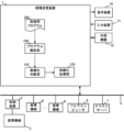
- FIG. 1 is a schematic hardware configuration diagram showing a main part of a path changing device according to an embodiment of the present disclosure.
- the functions of the path changing device 1 of the present disclosure can be implemented on a control device that controls an industrial machine such as a machine tool or a robot equipped with a moving object that moves when driven by a motor.
- the functions can be implemented on a computer such as a personal computer attached to the control device, a personal computer connected to the control device via a wired/wireless network, a cell computer, a fog computer 6, or a cloud server 7.
- the path changing device 1 in which each function is implemented on a control device that controls a machine tool that processes a workpiece by controlling the relative position between a tool and a workpiece will be described as an example.
- the CPU 11 provided in the route changing device 1 of the present disclosure is a processor that controls the route changing device 1 as a whole.
- the CPU 11 reads the system program stored in the ROM 12 via the bus 22, and controls the route changing device 1 as a whole in accordance with the system program.
- the RAM 13 temporarily stores temporary calculation data, display data, various data input from outside, etc.
- the non-volatile memory 14 is composed of, for example, a memory backed up by a battery (not shown) or an SSD (Solid State Drive), and retains its memory state even when the power to the route change device 1 is turned off.
- the non-volatile memory 14 stores control programs and data read from the external device 72 via the interface 15, data and control programs input via the input device 71, and various data acquired from the industrial machine 3.
- the control programs and data stored in the non-volatile memory 14 may be expanded in the RAM 13 when executed/used.
- various system programs such as well-known analysis programs are written in advance in the ROM 12.
- the interface 15 is an interface for connecting the CPU 11 of the path change device 1 to an external device 72 such as a USB memory, a compact flash (registered trademark), or an SD card.
- an external device 72 such as a USB memory, a compact flash (registered trademark), or an SD card.
- control programs and various data used to control the industrial machine 3 can be read from the external device 72.
- the control programs and various data edited in the path change device 1 can be stored in the external device 72.
- the PLC (Programmable Logic Controller) 16 outputs signals to the industrial machine 3 and its peripheral devices (for example, tool changers, actuators such as robots, sensors attached to the industrial machine 3, etc.) via the I/O unit 17 and controls them using a sequence program built into the path change device 1.
- the PLC 16 also receives signals from various switches on an operation panel installed on the main body of the industrial machine 3 and from peripheral devices, etc., and passes them to the CPU 11 after performing the necessary signal processing.
- Display device 70 displays various data loaded into memory, data obtained as a result of executing control programs and system programs, etc., output via interface 18.
- input device 71 which is composed of a keyboard, pointing device, etc., passes commands and data based on operations by the operator to CPU 11 via interface 19.
- the interface 20 is an interface for connecting the CPU 11 of the path change device 1 to a wired or wireless network 5.
- the network 5 may communicate using technologies such as serial communication such as RS-485, Ethernet (registered trademark), optical communication, wireless LAN, Wi-Fi (registered trademark), Bluetooth (registered trademark), etc.
- the network 5 is connected to other industrial machines 4, fog computers 6, cloud servers 7, etc., and exchanges data with the path change device 1.
- the axis control circuit 30 for controlling the drive axis of the industrial machine 3 receives a drive axis position command from the CPU 11 and outputs a command for the drive axis to the servo amplifier 40.
- the servo amplifier 40 receives this command and drives the servo motor 50, which is the drive axis, to move each part of the industrial machine 3 along each axis.
- Each servo motor 50 has a built-in position detector, and feeds back a position feedback signal from this position detector to the axis control circuit 30.
- the axis control circuit 30 performs feedback control of the servo motor 50 based on this position feedback signal. Note that in the hardware configuration diagram of FIG.
- axis control circuit 30, servo amplifier 40, and servo motor 50 are shown, but in reality, there are as many as the number of axes of the industrial machine 3 to be controlled.
- three sets of axis control circuits 30, servo amplifiers 40, and servo motors 50 are prepared to relatively move the spindle to which the tool is attached and the workpiece in the directions of the three linear axes (X-axis, Y-axis, and Z-axis).
- the spindle control circuit 60 receives a spindle rotation command and outputs a spindle speed signal to the spindle amplifier 61.
- the spindle amplifier 61 receives this spindle speed signal and rotates the spindle motor 62 of the industrial machine 3 at the commanded rotation speed to drive the spindle.
- a position coder 63 is connected to the spindle motor 62.
- the position coder 63 outputs a feedback pulse in synchronization with the rotation of the spindle, and the feedback pulse is read by the CPU 11.
- FIG. 2 is a schematic block diagram showing the functions of the route changing device 1 according to the first embodiment of the present disclosure.
- Each function of the route changing device 1 according to this embodiment is realized by the CPU 11 of the route changing device 1 shown in FIG. 1 executing a system program and controlling the operation of each part of the route changing device 1.
- the path change device 1 of this embodiment includes a program analysis unit 100, a curve formation determination unit 110, a curve formation processing unit 120, an interpolation unit 130, an acceleration/deceleration unit 140, and a servo control unit 150.
- the RAM 13 to the non-volatile memory 14 of the path change device 1 store a control program 200 for controlling the industrial machine 3.
- the program analysis unit 100 sequentially reads out blocks of the control program 200 and analyzes the read out blocks. Then, based on the analysis results, it creates a movement command related to a path for moving the drive unit equipped in the industrial machine 3. This path is, for example, a connection of multiple straight paths and multiple curved paths that take into account offset values such as tool diameter compensation.
- the program analysis unit 100 outputs the created movement command to the curved line determination unit 110.
- the curved line determination unit 110 determines whether to curve the paths related to two consecutive movement commands created by the program analysis unit 100.
- the curved line determination unit 110 detects at least one of the following as a reference value for curving: the difference in the curvature or radius of curvature of the path before and after the connection point of the paths related to each movement command, the difference in the angle of the path's progression direction or normal direction, and the distance to the center position of the circular arc of the path. Then, based on the reference value for curving, it determines whether or not to curve the paths at the connection point.
- the curved line determination unit 110 outputs the detected reference value and the determination result of whether or not to curve to the curved line processing unit 120.
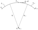
- FIG. 3 is a schematic diagram illustrating two connected arc paths.
- an arc path C i connecting points P i and P i+1 and an arc path C i+1 connecting points P i+1 and P i+2 are connected with point P i+1 as a connection point.
- the radius of curvature R i of the arc path C i is the same as the radius of curvature R i +1 of the arc path C i +1 .
- the direction of travel of the arc path C i just before point P i+1 which is the connection point, is the same as the direction of travel of the arc path C i +1 just after point P i+1 (connection angle ⁇ i is 0°).
- the curving judgment unit 110 may determine that curving is not necessary for the connection portion of point P i+1 .
- the curving judgment unit 110 may determine that curving processing is to be performed using predetermined curving parameters.
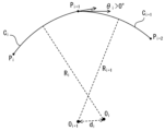
- FIG. 4 is a schematic diagram showing another example of two connected arc paths.
- an arc path C i connecting points P i and P i+1 and an arc path C i + 1 connecting points P i+1 and P i+2 are connected with point P i+1 as a connection part.
- the radius of curvature R i of the arc path C i is smaller than the radius of curvature R i +1 of the arc path C i +1.
- the direction of travel of the arc path C i just before point P i+1 which is the connection part, is the same as the direction of travel of the arc path C i+1 just after point P i+1 (connection angle ⁇ i is 0°).
- the distance d i between the center position of the arc path C i and the center position of the arc path C i+1 is greater than 0. This indicates that although the arc path C i and the arc path C i+1 are smoothly connected, a sudden change in curvature occurs. In such a case, the curved line forming determination unit 110 determines that the connection part of point P i+1 needs to be curved.
- FIG. 5 is a schematic diagram showing another example of two connected arc paths.
- an arc path C i connecting points P i and P i+1 and an arc path C i + 1 connecting points P i+1 and P i+2 are connected with point P i+1 as a connection part.
- the radius of curvature R i of the arc path C i is the same as the radius of curvature R i +1 of the arc path C i+ 1.
- the direction of travel of the arc path C i just before point P i+1 which is the connection part, is different from the direction of travel of the arc path C i +1 just after point P i+1 (the connection angle ⁇ i is 0° or more).
- the distance d i between the center position of the arc path C i and the center position of the arc path C i +1 is greater than 0. This indicates that although there is no sudden change in curvature between the arc path C i and the arc path C i+1 , they are not smoothly connected at the connection point. In such a case, the curved line determination unit 110 determines that the connection part of point P i+1 needs to be curved.
- FIG. 6 is a schematic diagram showing another example of two connected arc paths.
- an arc path C i connecting points P i and P i+1 and an arc path C i + 1 connecting points P i+1 and P i+2 are connected with point P i+1 as a connection part.
- the radius of curvature R i of the arc path C i is smaller than the radius of curvature R i +1 of the arc path C i +1.
- the direction of travel of the arc path C i just before point P i+1 which is the connection part, is different from the direction of travel of the arc path C i+1 just after point P i+1 (the connection angle ⁇ i is 0° or more).
- the distance d i between the center position of the arc path C i and the center position of the arc path C i+1 is greater than 0. This indicates that the arc path C i and the arc path C i+1 are not smoothly connected and that a sudden change in curvature also occurs. In such a case, the curved line forming determination unit 110 determines that the connection part of point P i+1 needs to be curved.
- FIG. 7 is a schematic diagram showing another example of two connected arc paths.
- an arc path C i connecting points P i and P i+1 and an arc path C i+1 connecting points P i + 1 and P i+2 are connected with point P i+1 as a connection part.
- the center position of the arc path C i and the center position of the arc path C i+1 are located on opposite sides of the path. In such a case, the distance d i between the arc center positions of the path becomes a very large value and cannot be used as a reference value for curving with the same criterion. Therefore, the curved path determining unit 110 may determine that curving is to be performed without imposing a limit on the tolerance.
- the curved line processing unit 120 performs a curved line processing on two consecutive paths that require curved line processing.
- the curved line processing may use known techniques such as a smoothing filter or a spline curve.
- the curved line processing unit 120 determines curved line parameters including at least one of the tolerance when curved line processing (maximum deviation between the path before curved line processing and the path after curved line processing) and the range of curved line processing, depending on reference values including at least one of the difference in the curvature or radius of curvature of the paths, the difference in the angle of the path's progression direction or normal direction, and the distance to the center position of the arc of the paths. Then, the curved line processing unit 120 curves the paths related to the two consecutive movement commands based on the determined curved line parameters.
- the curved line processing unit 120 outputs the curved movement command to the interpolation unit 130.
- the curve forming processing unit 120 may determine the tolerance T of the curve forming using a table or a formula that defines the relationship between the reference value and the tolerance T of the curve forming.
- FIG. 8 is a table diagram illustrating the relationship between the difference in the radius of curvature and the tolerance T.
- the following formula 1 shows an example of a formula that defines the relationship between the difference in the radius of curvature and the tolerance T.
- R s the smaller radius of curvature of the radii of curvature R i and R i+1 of two consecutive curved paths
- R l the larger radius of curvature
- FIG. 9 is a table illustrating the relationship between the difference in connection angle and the tolerance T.
- the following formula 2 shows an example of a formula that defines the relationship between the difference in connection angle and the tolerance T.
- R i and R i+1 the smaller radius of curvature of the two consecutive curved paths, R i and R i+1 , is indicated as R s .
- R s the smaller radius of curvature of the two consecutive curved paths
- a table or formula may be prepared that defines the relationship between the combination of multiple reference values and the tolerance T for curved line formation. Even in such a case, the relationship between the appropriate multiple reference values and the tolerance T can be determined in advance through experiments or the like and then defined.
- the curved line processing unit 120 may determine the curved line range L using a table or a formula that defines the relationship between the reference value and the curved line range L.
- FIG. 11 is a table diagram illustrating the relationship between the difference in the curvature radius and the curved line range L.
- the following formula 4 shows an example of a formula that defines the relationship between the difference in the curvature radius and the curved line range L.
- the smaller curvature radius of the two consecutive curved paths, R i and R i+1 is indicated as R s and the larger curvature radius is indicated as R l . As illustrated in FIG.
- FIG. 12 is a table illustrating the relationship between the difference in connection angle and the range L of curvature.
- the following formula 5 shows an example of a formula that defines the relationship between the difference in connection angle and the range L of curvature.
- the smaller radius of curvature of the two consecutive curved paths, R i and R i+1 is indicated as R s .
- R s the smaller radius of curvature of the two consecutive curved paths
- Fig. 13 is a table diagram illustrating an example of the relationship between the distance d i of the arc center position of the path and the curved line range L.
- the following formula 6 shows an example of a formula that defines the relationship between the distance of the arc center position of the path and the curved line range L.
- an appropriate relationship between the distance of the arc center position and the curved line range L can be obtained in advance by experiments or the like.
- a table or formula may be prepared that defines the relationship between the combination of multiple reference values and the range L of the curve. Even in such a case, the relationship between the appropriate multiple reference values and the range L of the curve can be determined and defined in advance through experiments, etc.
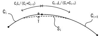
- Fig. 14 is a schematic diagram illustrating the relationship between the tolerance T, the curved range L, and a continuous path.
- the solid lines indicate two continuous paths C i and C i+1 instructed by a block of the control program 200.
- the dotted lines indicate a path S i generated by curved processing.
- curved processing is performed over a curved range L from C i L/(C i +C i+1 ) before the connection point of the two continuous paths C i and C i + 1 to C i+1 L/(C i +C i+1 ) after the connection point.
- the curved processing may be performed with the tolerance T set as the maximum deviation from the original path.
- the interpolation unit 130 performs an interpolation process to calculate the amount of movement for each axis of the industrial machine 3 per interpolation cycle. Then, it creates movement command data indicating the amount of movement for each axis per interpolation cycle. The interpolation unit 130 outputs the created movement command data for each interpolation cycle to the acceleration/deceleration unit 140.
- the acceleration/deceleration unit 140 performs post-interpolation acceleration/deceleration processing to adjust the amount of movement for each interpolation cycle for the movement command data for each interpolation cycle created by the interpolation unit 130.
- the post-interpolation acceleration/deceleration processing performed by the acceleration/deceleration unit 140 suppresses the magnitude of the first-order differential value in the movement of the drive unit along a specified axis based on the movement command data by, for example, applying an average filter to the movement command data for each interpolation cycle.
- the acceleration/deceleration unit 140 outputs the movement command data for each interpolation cycle that has been subjected to acceleration/deceleration processing to the servo control unit 150.
- the servo control unit 150 controls each servo motor 50 so that the drive unit of the industrial machine 3 moves along each axis based on the movement command data for each interpolation period input from the acceleration/deceleration unit 140.
- the path change device 1 which is configured as described above, can select appropriate curved line parameters for each continuous path commanded by a block of the control program 200 that includes an arc, and perform the curved line processing. This reduces the change in acceleration that occurs at the connection of the blocks, and is expected to improve the machining accuracy.
- the route changing device 1 determines a reference radius R0 when making two consecutive routes into a curve, and makes the route into a curve based on this reference radius R0 .
- the path changing device 1 like the path changing device 1 according to the first embodiment, includes a program analysis unit 100, a curve forming determination unit 110, a curve forming processing unit 120, an interpolation unit 130, an acceleration/deceleration unit 140, and a servo control unit 150.
- the RAM 13 to the non-volatile memory 14 of the path changing device 1 store a control program 200 for controlling the industrial machine 3.
- the program analysis unit 100, curved line determination unit 110, interpolation unit 130, acceleration/deceleration unit 140, and servo control unit 150 of this embodiment have the same functions as the program analysis unit 100, curved line determination unit 110, interpolation unit 130, acceleration/deceleration unit 140, and servo control unit 150 of the first embodiment.
- the curved line processing unit 120 When performing curved line processing between paths related to two consecutive movement commands, the curved line processing unit 120 according to this embodiment enlarges or reduces the curved line having a smaller radius of curvature among the paths so that the radius of curvature is the same as that of a circle having a predetermined reference radius R0 .
- the reference radius R0 is set to an appropriate value (e.g., 10 mm) according to the parameter value used in the curved line processing.
- the other path is also enlarged or reduced at the same ratio before the curved line processing is performed. After the curved line processing, each path is reduced or enlarged at the opposite ratio.
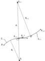
- FIG. 15 is a schematic diagram for explaining the enlargement/reduction process of a curved path.
- an arc path C i connecting points P i and P i+1 and an arc path C i +1 connecting points P i+1 and P i+2 are connected with point P i+1 as a connection part.
- the radius of curvature R i of the arc path C i is smaller than the radius of curvature R i +1 of the arc path C i +1 .
- the radius of curvature R i of the arc path C i is represented as R S and the radius of curvature R i of the arc path C i is represented as R l .
- the curved path processing unit 120 Before performing the curved path processing, the curved path processing unit 120 enlarges or reduces the arc path with the smaller radius of curvature so that the radius of curvature is the same as the reference radius R 0 .
- an arc path C i ' is created by multiplying (enlarging) the arc path C i by R 0 /R s .
- an arc path C i+1 ' is created by similarly multiplying (enlarging) the other path, the arc path C i+1 , by R 0 /R s , and connected to the arc path C i ' at the same connection angle as before the enlargement.
- the curve processing unit 120 performs curve processing on the two consecutive arc paths thus enlarged in the same manner as described in the first embodiment. Then, the path after the curve processing is reduced by R s /R 0 times.
- the tolerance T When a route is enlarged to form a curve, the tolerance T may become larger than expected.
- a tolerance limit value Tmax is set in advance, and if the tolerance T set during the curve forming process exceeds the tolerance limit value Tmax , the enlarged route is reduced by Tmax /T before the curve forming process is performed.
- the path changing device 1 performs a curved line processing on a path that has been enlarged or reduced in accordance with a circle of a predetermined reference radius R0 , so that the ratio of the tolerance and length with respect to the radius of curvature becomes constant, and the visual balance of the arc shape is maintained.
- the feed rate also decreases, so the machining shape precision is maintained, and it can be expected that more appropriate curved line processing can be performed.
- the following describes a route changing device 1 according to a third embodiment.
- the route changing device 1 according to the present embodiment adjusts the speed at a curved portion when two consecutive routes are curved.
- the path changing device 1 like the path changing device 1 according to the first embodiment, includes a program analysis unit 100, a curve forming determination unit 110, a curve forming processing unit 120, an interpolation unit 130, an acceleration/deceleration unit 140, and a servo control unit 150.
- the RAM 13 to the non-volatile memory 14 of the path changing device 1 store a control program 200 for controlling the industrial machine 3.
- the program analysis unit 100, curved line determination unit 110, interpolation unit 130, acceleration/deceleration unit 140, and servo control unit 150 of this embodiment have the same functions as the program analysis unit 100, curved line determination unit 110, interpolation unit 130, acceleration/deceleration unit 140, and servo control unit 150 of the first embodiment.
- the curved processing unit 120 When performing curved processing between paths related to two consecutive movement commands, the curved processing unit 120 according to this embodiment adjusts the feed speed before and after the connection part of the paths so that the feed speed changes monotonically from the feed speed before the connection part to the feed speed after the connection part. For example, when connecting an arc with a small radius of curvature to an arc with a large radius of curvature with a curve, the feed speed on the inserted curve continues to increase gradually without decreasing midway. In general, the feed speed of the arc part becomes smaller as the radius of curvature becomes smaller. Therefore, at the connection part of two consecutive paths with different curvatures, a sudden change in feed speed occurs. Therefore, the acceleration and deceleration are adjusted so that the feed speed changes gradually to prevent a sudden change in feed speed.
- This adjustment may be performed by adjusting the normal acceleration.
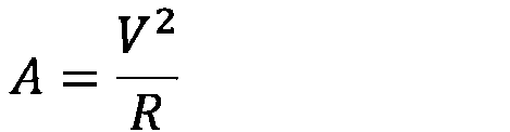
- the normal acceleration A when moving along an arc path can be expressed by the following equation 7, where the feed speed is V and the radius of curvature is R.
- the curved line processing unit 120 may adjust the feed speed V so that, for example, in the curved line range L, the normal acceleration changes gradually from the normal acceleration before the connection to the normal acceleration after the connection.
- the path changing device 1 which is configured as described above, adjusts the feed speed on a curved path so that the speed does not change suddenly before and after the connection. This is expected to suppress sudden changes in acceleration that occur at the connection of machining blocks that involve arcs, improving machining accuracy, and minimizing deterioration of the shape of the arc.
- the path changing device 1 In the above embodiment, an example is shown in which the path changing device 1 according to the present disclosure is implemented on a control device of an industrial machine. However, as illustrated in FIG. 16, the functions up to the curved line processing may be implemented on a computer. In such a configuration, the path changing device 1 reads each block of the control program 200 and creates a movement command that has been subjected to the curved line processing. The created movement command may then be passed to the control device 2 for use in controlling the industrial machine 3. At this time, the path changing device 1 may pass the curved line movement command to the control device 2 via the network 5, or may cause the control device 2 to read the curved line movement command stored in the external device 72.
- a path changing device (1) includes a program analysis unit (100) that sequentially reads blocks from a control program (200) and analyzes commands using the blocks; a curvature determination unit (110) that, when two consecutive movement commands include arc commands, detects reference values related to curvature, including at least one of a difference in curvature or radius of curvature, a difference in angle between the direction of travel or the normal direction, and a distance between arc center positions, in each of the movement commands, and determines whether or not curvature is required at a connection portion of the paths related to the movement commands based on the reference values; and a curvature processing unit (120) that determines curvature parameters for a path that requires curvature, including at least one of a tolerance, which is a maximum deviation of the path before and after curving, and a curvature range, based on the reference values related to curvature, and curves the path
- the curve forming determination unit (110) provided in a route changing device (1) according to another aspect of the present disclosure determines that curve forming should be performed using a predetermined curve forming parameter when the reference value for the curve forming is 0.
- the curve forming processing unit (120) provided in a path changing device (1) according to another aspect of the present disclosure enlarges or reduces the path related to the movement command to fit a circle of a predetermined reference radius, curves the enlarged or reduced path, and then reduces or enlarges the curved path.
- the curve forming processing unit (120) provided in a route changing device (1) according to another aspect of the present disclosure reduces the enlarged route and then curves the route so as not to exceed a predetermined tolerance limit value.
- a path change device (1) according to another aspect of the present disclosure adjusts the feed speed so that the feed speed before and after the connection part of the path changes monotonically.
- the route changing device according to claim 1 The route changing device according to claim 1 .
- a path change device (1) according to another aspect of the present disclosure adjusts the feed speed so that the normal acceleration before and after the connection part of the path changes gradually.
- a computer-readable recording medium causes a computer to function as: a program analysis unit (100) that sequentially reads blocks from a control program (200) and analyzes commands using the blocks; a curvature determination unit (110) that, when two consecutive movement commands include arc commands, detects reference values related to curvature, including at least one of the difference in curvature or radius of curvature, the difference in angle between the traveling direction or normal direction, and the distance between arc center positions, in each of the movement commands, and determines whether or not curvature is required at a connection portion of paths related to the movement commands based on the reference values; and a curvature processing unit (120) that determines curvature parameters for a path that requires curvature, including at least one of a tolerance, which is the maximum deviation of the path before and after curving, and a curvature range, based on the reference values related to curvature, and curves the path based on the determined curvature parameters, and the curva
Landscapes
- Engineering & Computer Science (AREA)
- Computing Systems (AREA)
- Theoretical Computer Science (AREA)
- Human Computer Interaction (AREA)
- Manufacturing & Machinery (AREA)
- Physics & Mathematics (AREA)
- General Physics & Mathematics (AREA)
- Automation & Control Theory (AREA)
- Numerical Control (AREA)
Abstract
Description
図1は本開示の一実施形態による経路変更装置の要部を示す概略的なハードウェア構成図である。本開示の経路変更装置1の機能は、モータが駆動することで移動する移動対象を備えた工作機械やロボットなどの産業機械を制御する制御装置の上に実装することができる。また、制御装置に併設されたパソコンや、該制御装置と有線/無線のネットワークを介して接続されたパソコン、セルコンピュータ、フォグコンピュータ6、クラウドサーバ7などのコンピュータ上に実装することができる。本実施形態では、工具とワークとの相対位置を制御することでワークを加工する工作機械を制御する制御装置の上に各機能を実装した経路変更装置1を例として説明する。






以下では、第2実施形態による経路変更装置1について説明する。本実施形態による経路変更装置1は、2つの連続する経路を曲線化する際に基準半径R0を定め、この基準半径R0に基づいて曲線化を行う。
以下では、第3実施形態による経路変更装置1について説明する。本実施形態による経路変更装置1は、2つの連続する経路を曲線化する際に曲線部における速度を調節する。
上記した実施形態では、本開示による経路変更装置1を産業機械の制御装置上に実装した例を示した。しかしながら、図16に例示するように、曲線化の処理を行うまでの機能をコンピュータ上に実装するようにしてもよい。このように構成する場合、経路変更装置1は、制御用プログラム200の各ブロックを読み込んで曲線化処理を施した移動指令を作成する。そして作成した移動指令を制御装置2に渡して産業機械3の制御に用いるようにすればよい。この時、経路変更装置1は、曲線化した移動指令をネットワーク5を介して制御装置2に渡してもよいし、外部機器72に記憶した曲線化した移動指令を制御装置2へと読み込ませるようにしてもよい。
(付記1)
本開示の一態様による経路変更装置(1)は、制御用プログラム(200)からブロックを順次読み込み、該ブロックにより指令を解析するプログラム解析部(100)と、連続する2つの移動指令が円弧指令を含む場合、それぞれの当該移動指令における曲率または曲率半径の違い、進行方向または法線方向の角度の違い、及び円弧中心位置の距離の少なくともいずれかを含む曲線化に係る基準値を検出し、該基準値に基づいて当該移動指令に係る経路の接続部における曲線化の要否を判断する曲線化判断部(110)と、曲線化が必要された経路について、曲線化に係る前記基準値に基づいて、曲線化する前後の経路の最大乖離量であるトレランス及び曲線化する範囲の少なくともいずれかを含む曲線化パラメータを決定し、決定した前記曲線化パラメータに基づいて前記経路を曲線化する曲線化処理部(120)と、を備え、前記曲線化処理部(120)が決定する前記曲線化パラメータは、前記基準値が増加した場合に同じ値または増加する。
本開示の他の態様による経路変更装置(1)が備える前記曲線化判断部(110)は、前記曲線化に係る基準値が0である場合、予め定めた所定の曲線化パラメータを用いて曲線化をすると判断する。
(付記3)
本開示の他の態様による経路変更装置(1)が備える前記曲線化処理部(120)は、予め定めた所定の基準半径の円に併せて前記移動指令に係る経路を拡大又は縮小し、該拡大又は縮小した経路を曲線化した上で、曲線化した経路を縮小又は拡大する。
本開示の他の態様による経路変更装置(1)が備える前記曲線化処理部(120)は、予め定めた所定のトレランス制限値を超えないように、拡大した前記経路を縮小してから経路の曲線化をする。
(付記5)
本開示の他の態様による経路変更装置(1)は、前記経路の接続部の前後の送り速度が単調に変化するように送り速度を調整する。
、
請求項1に記載の経路変更装置。
(付記6)
本開示の他の態様による経路変更装置(1)は、前記経路の接続部の前後の法線加速度が緩やかに変化するように送り速度を調整する。
本開示の一態様によるコンピュータ読み取り可能な記録媒体は、制御用プログラム(200)からブロックを順次読み込み、該ブロックにより指令を解析するプログラム解析部(100)、連続する2つの移動指令が円弧指令を含む場合、それぞれの当該移動指令における曲率または曲率半径の違い、進行方向または法線方向の角度の違い、及び円弧中心位置の距離の少なくともいずれかを含む曲線化に係る基準値を検出し、該基準値に基づいて当該移動指令に係る経路の接続部における曲線化の要否を判断する曲線化判断部(110)、曲線化が必要された経路について、曲線化に係る前記基準値に基づいて、曲線化する前後の経路の最大乖離量であるトレランス及び曲線化する範囲の少なくともいずれかを含む曲線化パラメータを決定し、決定した前記曲線化パラメータに基づいて前記経路を曲線化する曲線化処理部(120)、としてコンピュータを機能させ、前記曲線化処理部(120)が決定する前記曲線化パラメータは、前記基準値が増加した場合に同じ値または増加する。
3 産業機械
4 産業機械
5 ネットワーク
6 フォグコンピュータ
7 クラウドサーバ
11 CPU
12 ROM
13 RAM
14 不揮発性メモリ
15,18,19,20 インタフェース
16 PLC
17 I/Oユニット
22 バス
30 軸制御回路
40 サーボアンプ
50 サーボモータ
60 スピンドル制御回路
61 スピンドルアンプ
62 スピンドルモータ
63 ポジションコーダ
70 表示装置
71 入力装置
72 外部機器
100 プログラム解析部
110 曲線化判断部
120 曲線化処理部
130 補間部
140 加減速部
150 サーボ制御部
200 制御用プログラム
Claims (7)
- 制御用プログラムからブロックを順次読み込み、該ブロックにより指令を解析するプログラム解析部と、
連続する2つの移動指令が円弧指令を含む場合、それぞれの当該移動指令における曲率または曲率半径の違い、進行方向または法線方向の角度の違い、及び円弧中心位置の距離の少なくともいずれかを含む曲線化に係る基準値を検出し、該基準値に基づいて当該移動指令に係る経路の接続部における曲線化の要否を判断する曲線化判断部と、
曲線化が必要された経路について、曲線化に係る前記基準値に基づいて、曲線化する前後の経路の最大乖離量であるトレランス及び曲線化する範囲の少なくともいずれかを含む曲線化パラメータを決定し、決定した前記曲線化パラメータに基づいて前記経路を曲線化する曲線化処理部と、
を備え、
前記曲線化処理部が決定する前記曲線化パラメータは、前記基準値が増加した場合に同じ値または増加する、
経路変更装置。 - 前記曲線化判断部は、前記曲線化に係る基準値が0である場合、予め定めた所定の曲線化パラメータを用いて曲線化をすると判断する、
請求項1に記載の経路変更装置。 - 前記曲線化処理部は、予め定めた所定の基準半径の円に併せて前記移動指令に係る経路を拡大又は縮小し、該拡大又は縮小した経路を曲線化した上で、曲線化した経路を縮小又は拡大する、
請求項1に記載の経路変更装置。 - 前記曲線化処理部は、予め定めた所定のトレランス制限値を超えないように、拡大した前記経路を縮小してから経路の曲線化をする、
請求項3に記載の経路変更装置。 - 前記経路の接続部の前後の送り速度が単調に変化するように送り速度を調整する、
請求項1に記載の経路変更装置。 - 前記経路の接続部の前後の法線加速度が緩やかに変化するように送り速度を調整する、
請求項1に記載の経路変更装置。 - 制御用プログラムからブロックを順次読み込み、該ブロックにより指令を解析するプログラム解析部、
連続する2つの移動指令が円弧指令を含む場合、それぞれの当該移動指令における曲率または曲率半径の違い、進行方向または法線方向の角度の違い、及び円弧中心位置の距離の少なくともいずれかを含む曲線化に係る基準値を検出し、該基準値に基づいて当該移動指令に係る経路の接続部における曲線化の要否を判断する曲線化判断部、
曲線化が必要された経路について、曲線化に係る前記基準値に基づいて、曲線化する前後の経路の最大乖離量であるトレランス及び曲線化する範囲の少なくともいずれかを含む曲線化パラメータを決定し、決定した前記曲線化パラメータに基づいて前記経路を曲線化する曲線化処理部、
としてコンピュータを機能させ、
前記曲線化処理部が決定する前記曲線化パラメータは、前記基準値が増加した場合に同じ値または増加する、
プログラムを記録したコンピュータ読み取り可能な記録媒体。
Priority Applications (4)
| Application Number | Priority Date | Filing Date | Title |
|---|---|---|---|
| JP2025541175A JPWO2025041213A1 (ja) | 2023-08-18 | 2023-08-18 | |
| DE112023006502.0T DE112023006502T5 (de) | 2023-08-18 | 2023-08-18 | Bahnmodifizierungsvorrichtung und computerlesbares Aufzeichnungsmedium |
| PCT/JP2023/029909 WO2025041213A1 (ja) | 2023-08-18 | 2023-08-18 | 経路変更装置、及びコンピュータ読み取り可能な記録媒体 |
| CN202380101351.9A CN121713130A (zh) | 2023-08-18 | 2023-08-18 | 路径变更装置以及计算机可读取的记录介质 |
Applications Claiming Priority (1)
| Application Number | Priority Date | Filing Date | Title |
|---|---|---|---|
| PCT/JP2023/029909 WO2025041213A1 (ja) | 2023-08-18 | 2023-08-18 | 経路変更装置、及びコンピュータ読み取り可能な記録媒体 |
Publications (2)
| Publication Number | Publication Date |
|---|---|
| WO2025041213A1 true WO2025041213A1 (ja) | 2025-02-27 |
| WO2025041213A9 WO2025041213A9 (ja) | 2026-01-02 |
Family
ID=94731655
Family Applications (1)
| Application Number | Title | Priority Date | Filing Date |
|---|---|---|---|
| PCT/JP2023/029909 Pending WO2025041213A1 (ja) | 2023-08-18 | 2023-08-18 | 経路変更装置、及びコンピュータ読み取り可能な記録媒体 |
Country Status (4)
| Country | Link |
|---|---|
| JP (1) | JPWO2025041213A1 (ja) |
| CN (1) | CN121713130A (ja) |
| DE (1) | DE112023006502T5 (ja) |
| WO (1) | WO2025041213A1 (ja) |
Citations (4)
| Publication number | Priority date | Publication date | Assignee | Title |
|---|---|---|---|---|
| WO2012026279A1 (ja) * | 2010-08-25 | 2012-03-01 | 三菱電機株式会社 | 軌跡制御装置 |
| JP2014021759A (ja) * | 2012-07-19 | 2014-02-03 | Fanuc Ltd | コーナ複数曲線挿入部を有する数値制御装置 |
| JP2020019125A (ja) * | 2018-08-03 | 2020-02-06 | パナソニックIpマネジメント株式会社 | ロボット制御方法 |
| WO2021049028A1 (ja) * | 2019-09-13 | 2021-03-18 | 三菱電機株式会社 | 数値制御装置、および機械学習装置 |
Family Cites Families (1)
| Publication number | Priority date | Publication date | Assignee | Title |
|---|---|---|---|---|
| JP5845228B2 (ja) | 2013-10-23 | 2016-01-20 | ファナック株式会社 | 工具経路曲線化装置 |
-
2023
- 2023-08-18 JP JP2025541175A patent/JPWO2025041213A1/ja active Pending
- 2023-08-18 DE DE112023006502.0T patent/DE112023006502T5/de active Pending
- 2023-08-18 CN CN202380101351.9A patent/CN121713130A/zh active Pending
- 2023-08-18 WO PCT/JP2023/029909 patent/WO2025041213A1/ja active Pending
Patent Citations (4)
| Publication number | Priority date | Publication date | Assignee | Title |
|---|---|---|---|---|
| WO2012026279A1 (ja) * | 2010-08-25 | 2012-03-01 | 三菱電機株式会社 | 軌跡制御装置 |
| JP2014021759A (ja) * | 2012-07-19 | 2014-02-03 | Fanuc Ltd | コーナ複数曲線挿入部を有する数値制御装置 |
| JP2020019125A (ja) * | 2018-08-03 | 2020-02-06 | パナソニックIpマネジメント株式会社 | ロボット制御方法 |
| WO2021049028A1 (ja) * | 2019-09-13 | 2021-03-18 | 三菱電機株式会社 | 数値制御装置、および機械学習装置 |
Also Published As
| Publication number | Publication date |
|---|---|
| WO2025041213A9 (ja) | 2026-01-02 |
| CN121713130A (zh) | 2026-03-20 |
| JPWO2025041213A1 (ja) | 2025-02-27 |
| DE112023006502T5 (de) | 2026-04-16 |
Similar Documents
| Publication | Publication Date | Title |
|---|---|---|
| JP5417392B2 (ja) | 数値制御装置 | |
| US7070368B2 (en) | Method for setting a machining feed rate and a machine tool using the same | |
| EP2293163B1 (en) | Controller for machine tool and five-axis simultaneous control machine tool controlled thereby | |
| JP6646027B2 (ja) | ポストプロセッサ装置、加工プログラム生成方法、cnc加工システム及び加工プログラム生成用プログラム | |
| JP2010511919A (ja) | 許容差ベースの経路設計と制御の方法 | |
| WO2013018340A1 (ja) | 数値制御装置 | |
| US7083368B2 (en) | Numerical control apparatus | |
| JP7415093B1 (ja) | 制御装置及びコンピュータ読み取り可能な記録媒体 | |
| CN103707128A (zh) | 螺纹切削机 | |
| CN116134390B (zh) | 至少双轴的机床的运行 | |
| JP7428793B2 (ja) | 加工経路作成装置 | |
| WO2014002381A1 (ja) | 数値制御装置 | |
| WO2022138843A1 (ja) | 数値制御装置 | |
| JP2020003958A (ja) | 数値制御装置 | |
| WO2025041213A9 (ja) | 経路変更装置、及びコンピュータ読み取り可能な記録媒体 | |
| JP2008117032A (ja) | 加工制御装置およびそのプログラム | |
| WO2021193728A1 (ja) | 工作機械の制御装置、制御システム、及び制御方法 | |
| CN101893874B (zh) | 四轴加工机用数值控制装置 | |
| CN112114558A (zh) | 数值控制装置、cnc机床、数值控制方法以及记录有数值控制用程序的计算机可读介质 | |
| WO2025013209A1 (ja) | 制御装置、及びコンピュータ読み取り可能な記録媒体 | |
| JP7109490B2 (ja) | 数値制御方法及び数値制御装置 | |
| JP4982170B2 (ja) | 加工制御装置および加工制御プログラム | |
| JP7355951B1 (ja) | 制御装置及びコンピュータ読み取り可能な記録媒体 | |
| JP7583057B2 (ja) | 制御装置 | |
| JP3520142B2 (ja) | 象限突起補正パラメータ決定装置 |
Legal Events
| Date | Code | Title | Description |
|---|---|---|---|
| 121 | Ep: the epo has been informed by wipo that ep was designated in this application |
Ref document number: 23949674 Country of ref document: EP Kind code of ref document: A1 |
|
| ENP | Entry into the national phase |
Ref document number: 2025541175 Country of ref document: JP Kind code of ref document: A |
|
| WWE | Wipo information: entry into national phase |
Ref document number: 2025541175 Country of ref document: JP |
|
| WWE | Wipo information: entry into national phase |
Ref document number: 112023006502 Country of ref document: DE |
|
| WWP | Wipo information: published in national office |
Ref document number: 112023006502 Country of ref document: DE |