WO2025041200A1 - 撮像装置および撮像システム - Google Patents
撮像装置および撮像システム Download PDFInfo
- Publication number
- WO2025041200A1 WO2025041200A1 PCT/JP2023/029883 JP2023029883W WO2025041200A1 WO 2025041200 A1 WO2025041200 A1 WO 2025041200A1 JP 2023029883 W JP2023029883 W JP 2023029883W WO 2025041200 A1 WO2025041200 A1 WO 2025041200A1
- Authority
- WO
- WIPO (PCT)
- Prior art keywords
- light
- image
- opening
- imaging
- polarization direction
- Prior art date
- Legal status (The legal status is an assumption and is not a legal conclusion. Google has not performed a legal analysis and makes no representation as to the accuracy of the status listed.)
- Pending
Links
Images











Classifications
-
- G—PHYSICS
- G02—OPTICS
- G02B—OPTICAL ELEMENTS, SYSTEMS OR APPARATUS
- G02B7/00—Mountings, adjusting means, or light-tight connections, for optical elements
- G02B7/02—Mountings, adjusting means, or light-tight connections, for optical elements for lenses
-
- G—PHYSICS
- G03—PHOTOGRAPHY; CINEMATOGRAPHY; ANALOGOUS TECHNIQUES USING WAVES OTHER THAN OPTICAL WAVES; ELECTROGRAPHY; HOLOGRAPHY
- G03B—APPARATUS OR ARRANGEMENTS FOR TAKING PHOTOGRAPHS OR FOR PROJECTING OR VIEWING THEM; APPARATUS OR ARRANGEMENTS EMPLOYING ANALOGOUS TECHNIQUES USING WAVES OTHER THAN OPTICAL WAVES; ACCESSORIES THEREFOR
- G03B11/00—Filters or other obturators specially adapted for photographic purposes
-
- G—PHYSICS
- G03—PHOTOGRAPHY; CINEMATOGRAPHY; ANALOGOUS TECHNIQUES USING WAVES OTHER THAN OPTICAL WAVES; ELECTROGRAPHY; HOLOGRAPHY
- G03B—APPARATUS OR ARRANGEMENTS FOR TAKING PHOTOGRAPHS OR FOR PROJECTING OR VIEWING THEM; APPARATUS OR ARRANGEMENTS EMPLOYING ANALOGOUS TECHNIQUES USING WAVES OTHER THAN OPTICAL WAVES; ACCESSORIES THEREFOR
- G03B35/00—Stereoscopic photography
- G03B35/08—Stereoscopic photography by simultaneous recording
-
- G—PHYSICS
- G03—PHOTOGRAPHY; CINEMATOGRAPHY; ANALOGOUS TECHNIQUES USING WAVES OTHER THAN OPTICAL WAVES; ELECTROGRAPHY; HOLOGRAPHY
- G03B—APPARATUS OR ARRANGEMENTS FOR TAKING PHOTOGRAPHS OR FOR PROJECTING OR VIEWING THEM; APPARATUS OR ARRANGEMENTS EMPLOYING ANALOGOUS TECHNIQUES USING WAVES OTHER THAN OPTICAL WAVES; ACCESSORIES THEREFOR
- G03B9/00—Exposure-making shutters; Diaphragms
- G03B9/02—Diaphragms
-
- H—ELECTRICITY
- H04—ELECTRIC COMMUNICATION TECHNIQUE
- H04N—PICTORIAL COMMUNICATION, e.g. TELEVISION
- H04N13/00—Stereoscopic video systems; Multi-view video systems; Details thereof
- H04N13/20—Image signal generators
- H04N13/204—Image signal generators using stereoscopic image cameras
- H04N13/207—Image signal generators using stereoscopic image cameras using a single two-dimensional [2D] image sensor
- H04N13/218—Image signal generators using stereoscopic image cameras using a single two-dimensional [2D] image sensor using spatial multiplexing
-
- H—ELECTRICITY
- H04—ELECTRIC COMMUNICATION TECHNIQUE
- H04N—PICTORIAL COMMUNICATION, e.g. TELEVISION
- H04N23/00—Cameras or camera modules comprising electronic image sensors; Control thereof
- H04N23/50—Constructional details
- H04N23/55—Optical parts specially adapted for electronic image sensors; Mounting thereof
Definitions
- the present invention relates to an imaging device and an imaging system.
- a known method for obtaining data regarding the depth of an object through image processing is to compare multiple disparity images obtained when viewing an object from different directions to detect the amount of disparity, and then determine the depth of the object from the detected amount of disparity.
- an imaging device such as that described in Patent Document 1 has been devised (see, for example, Patent Document 1). There is a demand for such an imaging device to obtain data regarding the depth of an object with a compact configuration.
- the imaging device comprises an imaging optical system that forms an image of an object, and an imaging element that images the image of the object formed through the imaging optical system, the imaging optical system having a first lens group, an optical unit, and a second lens group arranged in order from the object side along an optical axis, the imaging element having a plurality of pixels that perform photoelectric conversion of incident light that is incident on the imaging element, a first polarization section that transmits only light of a first polarization direction of the incident light and makes it incident on a first pixel of the plurality of pixels, and a second polarization section that transmits only light of a second polarization direction perpendicular to the first polarization direction of the incident light and makes it incident on a second pixel of the plurality of pixels.
- the optical unit has a diaphragm having a first opening formed at a position away from the optical axis of the imaging optical system and a second opening formed at a position opposite the first opening across the optical axis of the imaging optical system, a first polarizing element provided at the first opening that transmits only light in the first polarization direction, and a second polarizing element provided at the second opening that transmits only light in the second polarization direction, and the numerical aperture corresponding to the light ray passing through the centroid of the outer periphery of the first opening and incident on a position on the optical axis of the imaging element and the light ray passing through the centroid of the outer periphery of the second opening and incident on a position on the optical axis of the imaging element is 0.26 or less.
- the imaging system comprises an imaging optical system for forming an image of an object, an imaging element for capturing an image of the object captured via the imaging optical system, and a processing device for generating image data of the object captured by the imaging element, the imaging optical system having a first lens group, an optical unit, and a second lens group arranged in order from the object side along an optical axis, the imaging element having a plurality of pixels for performing photoelectric conversion of incident light entering the imaging element, a first polarization section for transmitting only light of a first polarization direction of the incident light and causing it to enter a first pixel of the plurality of pixels, and a second polarization section for transmitting only light of a second polarization direction perpendicular to the first polarization direction of the incident light and causing it to enter a second pixel of the plurality of pixels, and the optical unit is a polarization section of the imaging optical system.
- the processing device has an aperture having a first opening formed at a position away from the optical axis and a second opening formed at a position opposite the first opening across the optical axis of the imaging optical system, a first polarizing element provided at the first opening that transmits only light of the first polarization direction, and a second polarizing element provided at the second opening that transmits only light of the second polarization direction, and the processing device has an image processing unit that generates first image data regarding the image of the object formed with light of the first polarization direction and second image data regarding the image of the object formed with light of the second polarization direction based on image data of the object, and a position calculation unit that calculates data regarding the position of the object in the optical axis direction of the imaging optical system based on the first image data and the second image data.
- FIG. 1 is a schematic configuration diagram showing an imaging system according to an embodiment of the present invention.
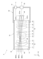
- 1 is a cross-sectional view of an imaging device according to an embodiment of the present invention.
- 4A to 4C are explanatory diagrams showing, in comparison, first incident light beams incident on an imaging element;
- 11A and 11B are explanatory diagrams showing, in comparison, a second incident light beam incident on the imaging element;
- 4 is a schematic diagram showing a first light ray and a second light ray incident on an imaging element;
- FIG. FIG. 2 is a schematic diagram showing the structure of an imaging element.
- FIG. 2 is an enlarged view showing a polarizing section in the image sensor.
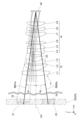
- FIG. FIG. 2 is a cross-sectional view of an imaging optical system.
- FIG. 1 is a graph showing the relationship between the angle of incidence of light incident on an imaging element and the signal strength of an image signal output from the imaging element.
- FIG. 2 is an explanatory diagram showing an example of an image of an object.
- 1 is a schematic diagram showing a case where an object plane is located at a focal position of an imaging optical system.
- 1 is a schematic diagram showing a case where an object surface is located closer than the focal position of an imaging optical system.
- 1 is a schematic diagram showing a case where an object surface is located farther away than the focal position of an imaging optical system.
- FIG. 13 is a front view showing an optical unit according to a first modified example.
- FIG. 11 is a front view showing an optical unit according to a second modified example.
- FIG. 13 is a front view showing an optical unit according to a third modified example.
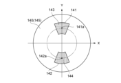
- FIG. 13 is a front view showing an optical unit according to a fourth modified example.
- FIG. 13 is a front view showing an optical unit according to a fifth modified example.
- FIG. 13 is a front view showing an optical unit according to a sixth modified example.
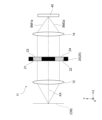
- FIG. 11 is a cross-sectional view showing a modified example of the imaging lens.
- FIG. 13 is a schematic diagram showing a modified example of the imaging element.
- 13 is an explanatory diagram showing an example of obtaining the depth of an object using an image sensor according to a modified example.
- FIG. 13 is an explanatory diagram showing another example of obtaining the depth of an object using an image pickup element according to a modified example.
- FIG. 13 is an explanatory diagram showing another example of obtaining the depth of an object using an image pickup element according to a modified example.
- FIG. 13 is an explanatory diagram showing another example of obtaining the depth of an object using an image pickup
- the directions indicated by the arrows in Figures 2 to 9 and Figures 12 to 22 may be referred to as the X direction, Y direction, and Z direction, respectively.
- the X direction, Y direction, and Z direction are mutually orthogonal.
- the Z direction is the direction along the optical axis of the imaging optical system described below.
- the imaging system 1 includes an imaging device 5 that captures an image of an object OB, and a processing device 60.
- the imaging system 1 according to this embodiment can be used, for example, in industrial robots, monitoring systems that monitor the condition of plants, unmanned aerial vehicles (drones), and automated guided vehicles (AGVs).
- the imaging device 5 includes an imaging lens 10 and a device body 30.
- the imaging lens 10 includes an imaging optical system 11 and a lens barrel 16.
- the lens barrel 16 houses and holds the imaging optical system 11 and is attached to the device body 30.
- each pixel (42a to 42d) of the pixel array section 41 has a pixel circuit (not shown) that generates an image signal based on the charge generated by the photoelectric conversion section.
- Each pixel (42a to 42d) of the pixel array section 41 outputs an image signal generated from the image signal to the signal output section 32.
- the polarizing array section 51 is arranged overlapping the pixel array section 41 near the object side.
- the polarizing array section 51 has a plurality of polarizing sections 52a to 52d arranged side by side in two dimensions (XY directions) corresponding to the plurality of pixels 42a to 42d.
- the plurality of polarizing sections include a first polarizing section 52a, a second polarizing section 52b, a third polarizing section 52c, and a fourth polarizing section 52d.
- the polarizing array section 51 is composed of a plurality of groups each consisting of the first to fourth polarizing sections 52a to 52d arranged in pairs in the XY directions.
- the third polarizing section 53 transmits only light of a third polarization direction different from the first and second polarization directions (e.g., a polarization direction rotated by 45° around the Z axis with respect to the X direction) of the incident light, and allows it to enter the third pixel 42c of the multiple pixels.
- the fourth polarizing section 54 transmits only light of a fourth polarization direction different from the first to third polarization directions (e.g., a polarization direction rotated by 135° around the Z axis with respect to the X direction) of the incident light, and allows it to enter the fourth pixel 42d of the multiple pixels.
- a microlens array section may also be disposed near the object side of the polarization array section 51.
- the microlens array section has a plurality of microlenses arranged in two dimensions (XY directions) corresponding to the plurality of pixels 42a to 42d (i.e., the plurality of polarization sections 52a to 52d).
- the microlens array section may be disposed between the pixel array section 41 and the polarization array section 51.
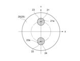
- the optical unit 20 has an aperture 25, a first polarizing element 23, and a second polarizing element 24.
- the aperture 25 has a first opening 21 and a second opening 22.
- the first opening 21 is formed in a circular shape at a position away from the optical axis AX of the imaging optical system 11 in the +Y direction.
- the second opening 22 is formed in a circular shape at a position away from the optical axis AX of the imaging optical system 11 in the -Y direction.
- the second opening 22 is formed in the same manner as the first opening 21 at a position opposite the first opening 21 across the optical axis AX of the imaging optical system 11.
- the first polarizing element 23 is provided in the first opening 21.
- the first polarizing element 23 transmits only the light having the first polarization direction among the light incident on the first opening 21.
- the second polarizing element 24 is provided in the second opening 22.
- the second polarizing element 24 transmits only the light having the second polarization direction among the light incident on the second opening 22.
- first incident light CD1a-CD1c first incident light CD1a-CD1c
- second incident light CD2a-CD2c second incident light CD2a-CD2c
- second incident light CD2a-CD2c second incident light CD2a-CD2c
- the aperture 25 is disposed at the front focal position of the second lens group 14. If the aperture 25 is not disposed at the front focal position of the second lens group 14, as shown on the left side of FIG. 3, the first light rays BM1b and BM1c incident on the imaging element 40 at an off-axis position will have a different angle of incidence with respect to the imaging element 40 compared to the first light ray BM1a incident on the imaging element 40 at a position on the optical axis AX. In particular, the first light ray BM1c incident on the imaging element 40 at an off-axis position on the -Y direction side will have an excessively large angle of incidence with respect to the imaging element 40 in FIG. 3, making it difficult to detect by the imaging element 40.
- the second light rays BM2b and BM2c incident on the imaging element 40 at an off-axis position will also have a different angle of incidence with respect to the imaging element 40 compared to the second light ray BM2a incident on the imaging element 40 at a position on the optical axis AX.
- the second light ray BM2b that is incident on the imaging element 40 at an off-axis position on the +Y side has an incident angle to the imaging element 40 that is too large in FIG. 4, making it difficult for the imaging element 40 to detect it.
- the first light rays BM1b and BM1c incident on the imaging element 40 at an off-axis position have the same angle of incidence to the imaging element 40 as the first light ray BM1a incident on the imaging element 40 at a position on the optical axis AX, as shown on the right side of FIG. 4. Also, as shown on the right side of FIG.
- the second light rays BM2b and BM2c incident on the imaging element 40 at an off-axis position have the same angle of incidence to the imaging element 40 as the second light ray BM2a incident on the imaging element 40 at a position on the optical axis AX, as shown on the right side of FIG. 5. Therefore, as shown in FIG. 5, the first light rays BM1a-BM1c and the second light rays BM2a-BM2c (i.e., the first incident light CD1a-CD1c and the second incident light CD2a-CD2c) incident on the imaging element 40 can be received at the same angle of incidence regardless of the position on the imaging element 40 (image surface).
- the second opening 22 is formed in the same manner as the first opening 21, at a position opposite the first opening 21 across the optical axis AX of the imaging optical system 11. Therefore, the angles of incidence of the first light rays BM1a to BM1c and the angles of incidence of the second light rays BM2a to BM2c can be set to have the same absolute value.
- the angle ⁇ 1 between the optical axis AX and the first light ray BM1a passing through the centroid 21a of the outer periphery of the first opening 21 and incident on the optical axis AX at the image sensor 40 (incidence angle of the first light ray BM1a)
- the angle ⁇ 2 between the optical axis AX and the second light ray BM2a passing through the centroid 22a of the outer periphery of the second opening 22 and incident on the optical axis AX at the image sensor 40 (incidence angle of the second light ray BM2a) have the same absolute value.
- the sine of the incidence angle ⁇ 1 of the first light ray BM1a in other words, the sine of the incidence angle ⁇ 2 of the second light ray BM2a
- the second light ray BM2a which passes through the centroid 22a of the outer periphery of the second opening 22 and is incident on a position on the optical axis AX of the image sensor 40.
- the value obtained by multiplying the sine of the incidence angle ⁇ 1 of the first light ray BM1a by the refractive index n of the medium is referred to as the numerical aperture corresponding to the first light ray BM1a that passes through the centroid 21a of the outer periphery of the first opening 21 and enters a position on the optical axis AX of the image sensor 40, and the second light ray BM2a that passes through the centroid 22a of the outer periphery of the second opening 22 and enters a position on the optical axis AX of the image sensor 40.
- the numerical aperture corresponding to the first light ray BM1a that passes through the centroid 21a of the outer periphery of the first opening 21 and enters a position on the optical axis AX of the image sensor 40, and the second light ray BM2a that passes through the centroid 22a of the outer periphery of the second opening 22 and enters a position on the optical axis AX of the image sensor 40, is set to 0.26.
- the sine of the opening angle on one side of the first incident light CD1a and second incident light CD2a that enter the image sensor 40 which corresponds to the radius of the first opening 21 and the second opening 22, is set to 0.063.
- an image sensor 40 having a polarizing array section 51 is more likely to have a reduced sensitivity when the angle of incidence of light incident on the image sensor increases. This is because the image sensor 40 having a polarizing array section 51 makes it more difficult for light to reach the pixel array section 41 by the thickness of the polarizing array section 51.
- the inventor of the present application investigated the relationship between the angle of incidence of light incident on the image sensor and the signal strength of the image signal output from the image sensor.
- FIG. 10 is a graph showing the relationship between the angle of incidence of light incident on the image sensor and the signal strength of the image signal output from the image sensor. The horizontal axis of the graph shown in FIG.
- FIG. 10 indicates the angle of incidence ⁇ (degrees) of light incident on the image sensor.
- the vertical axis of the graph shown in FIG. 10 indicates the signal strength K of the image signal output from the image sensor. From FIG. 10, it can be seen that in the signal strength distribution K1 for the image sensor 40 according to this embodiment, when the angle of incidence of light exceeds ⁇ 10 degrees, only half or less signal strength is obtained compared to when the angle of incidence of light is 0 degrees. In contrast, in the signal intensity distribution K2 for a general image sensor (e.g., CMOS) that does not have a polarization array section, it can be seen that even when the light incidence angle is ⁇ 10 degrees, the signal intensity is equivalent to that when the light incidence angle is 0 degrees. Note that the signal intensity distribution K1 for the image sensor 40 according to this embodiment gives similar results for light of the first to fourth polarization directions, so only the case of light of the first polarization direction is shown.
- the angle of incidence of the first light ray BM1a and the second light ray BM2a that enter the image sensor 40 can be set to a range smaller than ⁇ 15 degrees. This makes it possible to prevent a decrease in the signal strength of the image signal output from the image sensor 40.
- the processing device 60 is configured using, for example, a CPU (central processing unit) or the like. As shown in FIG. 1, the processing device 60 has a camera control unit 61, a signal acquisition unit 62, a storage unit 63, an image processing unit 64, a position calculation unit 65, and a data output unit 66.
- the camera control unit 61 controls the operation of the imaging device 5 based on a control program stored in the storage unit 63. For example, the camera control unit 61 outputs a drive signal for the imaging element 40 to the signal input unit 31 of the imaging device 5.
- the signal acquisition unit 62 acquires the image signal output from the imaging element 40 via the signal output unit 32 of the imaging device 5.
- the image processing unit 64 generates image data of the object OB imaged by the image sensor 40 based on the image signal from the image sensor 40 acquired by the signal acquisition unit 62.
- the image data of the object OB generated by the image processing unit 64 may be stored in the storage unit 63.
- the image data of the object OB generated by the image processing unit 64 may be output to an external device such as an image display device 68 via the data output unit 66, and an image M of the object OB (see FIG. 11) may be displayed on the image display device 68.
- the image sensor 40 has a polarization array section 51 composed of a plurality of groups each consisting of the first to fourth polarization sections 52a to 52d. Therefore, as shown in FIG. 11, from an image M of an object OB, an image M1 of the object OB formed by light in a first polarization direction, an image M2 of the object OB formed by light in a second polarization direction, an image M3 of the object OB formed by light in a third polarization direction, and an image M4 of the object OB formed by light in a fourth polarization direction can be extracted.
- the data of the image M1 of the object OB formed by light in the first polarization direction is referred to as the first image data.
- the data of the image M2 of the object OB formed by light in the second polarization direction is referred to as the second image data.
- FIG. 11 shows an example of each image of the object OB, and each image of the object OB is not limited to this.
- a first light ray BM1a passing through the centroid of first opening 21 is incident on a position on optical axis AX of image sensor 40.
- a second light ray BM2a passing through the centroid of second opening 22 is incident on a position on optical axis AX of image sensor 40.
- no parallax occurs between image M1 of object OB formed with light of the first polarization direction and image M2 of object OB formed with light of the second polarization direction.
- the image processing unit 64 can generate first image data relating to an image of the object OB formed by light in the first polarization direction and second image data relating to an image of the object OB formed by light in the second polarization direction based on the generated image data of the object OB.
- the image processing unit 64 may also correct unevenness in the amount of light in the first image data using image data of the first reference image RF1, and generate data of an image M1a after the light amount correction of the object OB formed by light in the first polarization direction.
- the image processing unit 64 may correct unevenness in the amount of light in the second image data using image data of the second reference image RF2, and generate data of an image M2a after the light amount correction of the object OB formed by light in the second polarization direction.
- the first reference image RF1 is an image of a white board or white paper extracted from an image of the white board or white paper, the image being formed with light in a first polarization direction.
- the second reference image RF2 is an image of a white board or white paper extracted from an image of the white board or white paper, the image being formed with light in a second polarization direction.
- the data of the image M1a of the object OB after light intensity correction, the image being formed with light in the first polarization direction is referred to as the first image data after light intensity correction.
- the data of the image M2a of the object OB after light intensity correction, the image being formed with light in the second polarization direction is referred to as the second image data after light intensity correction.
- the position calculation unit 65 calculates the position of the object OB in the optical axis direction (Z direction) of the imaging optical system 11, i.e., the depth of the object OB, based on the first image data and second image data after light intensity correction generated by the image processing unit 64. Specifically, the position calculation unit 65 calculates the amount of parallax between the image M1a after light intensity correction of the object OB imaged with light in the first polarization direction and the image M2a after light intensity correction of the object OB imaged with light in the second polarization direction, using a known method such as the BM (Block Matching) method or the SGBM (Semi-Global Block Matching) method, from the first image data and second image data after light intensity correction. Then, the position calculation unit 65 calculates the depth of the object OB from the calculated amount of parallax using the principle of triangulation.
- BM Block Matching
- SGBM Semi-Global Block Matching
- the data on the depth of the object OB calculated by the position calculation unit 65 may be stored in the storage unit 63.
- the image processing unit 64 may generate color image data of the object OB by converting the data on the depth of the object OB into color data.
- this color image data is referred to as depth image data of the object OB.
- the depth image data of the object OB generated by the image processing unit 64 may be stored in the storage unit 63.
- the data on the depth of the object OB calculated by the position calculation unit 65 and the depth image data of the object OB generated by the image processing unit 64 may be output to an external device such as the image display device 68 via the data output unit 66.
- the depth image MD of the object OB which is obtained by converting the data on the depth of the object OB into color data, may be displayed on the image display device 68.
- the image processing unit 64 may perform so-called texture mapping by superimposing the data on the depth of the object OB on the first image data or the second image data before the light amount correction.
- the imaging optical system 11 of the imaging device 5 forms an image of the object OB on an image plane (not shown).
- light from the object OB passes through the first lens group 12 of the imaging optical system 11 and reaches the diaphragm 25 provided in the optical unit 20.
- the above-mentioned first incident light CD1a to CD1c passes through the first opening 21 (first polarizing element 23) of the diaphragm 25, passes through the second lens group 14, and is incident on the imaging element 40.
- the above-mentioned second incident light CD2a to CD2c passes through the second opening 22 (second polarizing element 24) of the diaphragm 25, passes through the second lens group 14, and is incident on the imaging element 40.
- the imaging element 40 image plane
- light in the first polarization direction and the second polarization direction are imaged to form an image of the object OB.
- the image sensor 40 captures an image of the object OB formed through the imaging optical system 11 and outputs an image signal.
- the signal output unit 32 outputs the image signal from the image sensor 40 to the signal acquisition unit 62 of the processing device 60.
- the signal acquisition unit 62 of the processing device 60 acquires the image signal output from the imaging element 40 via the signal output unit 32 of the imaging device 5.
- the image processing unit 64 generates image data of the object OB imaged by the imaging element 40 based on the image signal from the imaging element 40 acquired by the signal acquisition unit 62.
- the image data of the object OB generated by the image processing unit 64 may be output to an external device such as an image display device 68 via the data output unit 66, and an image M of the object OB (see FIG. 11) may be displayed on the image display device 68.
- the image processing unit 64 also generates first image data relating to the image of the object OB formed by light in the first polarization direction and second image data relating to the image of the object OB formed by light in the second polarization direction based on the generated image data of the object OB.
- the image processing unit 64 uses the image data of the first reference image RF1 and the second reference image RF2 to correct the unevenness in the amount of light in the first image data to generate the first image data after the light amount correction, and corrects the unevenness in the amount of light in the second image data to generate the second image data after the light amount correction.
- the position calculation unit 65 calculates the position of the object OB in the optical axis direction (Z direction) of the imaging optical system 11, i.e., the depth of the object OB, based on the first image data and the second image data after the light amount correction generated by the image processing unit 64.
- the image processing unit 64 may generate depth image data of the object OB by converting the data relating to the depth of the object OB into color data. This makes it possible to generate three-dimensional image data (depth image data) of the object OB in addition to two-dimensional image data of the object OB.
- data regarding the depth of the object OB calculated by the position calculation unit 65 and depth image data of the object OB generated by the image processing unit 64 may be output to an external device such as an image display device 68 via the data output unit 66.
- the depth image MD of the object OB may be displayed on the image display device 68.
- the optical unit 20 has a diaphragm 25 having a first opening 21 formed at a position away from the optical axis AX of the imaging optical system 11 and a second opening 22 formed at a position opposite the first opening 21 across the optical axis AX of the imaging optical system 11, a first polarizing element 23 provided at the first opening 21 to transmit only light of a first polarization direction, and a second polarizing element 24 provided at the second opening 22 to transmit only light of a second polarization direction.
- parallax occurs between an image M1 of the object OB formed by light of the first polarization direction and an image M2 of the object OB formed by light of the second polarization direction.
- the numerical aperture corresponding to the first light ray BM1a that passes through the centroid 21a of the outer periphery of the first opening 21 and enters a position on the optical axis AX of the image sensor 40, and the second light ray BM2a that passes through the centroid 22a of the outer periphery of the second opening 22 and enters a position on the optical axis AX of the image sensor 40 is set to 0.26 or less.
- the aperture 25 of the optical unit 20 is disposed at the front focal position of the second lens group 14.
- the first light rays BM1a-BM1c and the second light rays BM2a-BM2c i.e., the first incident light rays CD1a-CD1c and the second incident light rays CD2a-CD2c
- the image sensor 40 can be received at the same angle of incidence regardless of the position on the image sensor 40 (image surface). This makes it possible to prevent a decrease in the signal strength of the image signal output from the image sensor 40.
- the processing device 60 also has an image processing unit 64 that generates first image data relating to the image of the object OB formed by light in the first polarization direction and second image data relating to the image of the object OB formed by light in the second polarization direction, and a position calculation unit 65 that determines data relating to the position of the object OB in the optical axis direction of the imaging optical system 11 based on the first image data and the second image data.
- This makes it possible to obtain data relating to the position of the object OB in the optical axis direction of the imaging optical system 11, i.e., the depth of the object OB, with a compact configuration that uses only one imaging device 5 (imaging optical system 11 and image sensor 40).
- the first polarizing element 23 of the optical unit 20 is provided inside the first opening 21 in the aperture 25, and the second polarizing element 24 is provided inside the second opening 22 in the aperture 25, but this is not limited to the above.
- the first polarizing element may be provided adjacent to the image surface side of the first opening 21 in the aperture 25, and the second polarizing element may be provided adjacent to the image surface side of the second opening 22 in the aperture 25.
- the aperture 25 may be disposed at the front focal position of the optical system combining the first polarizing element, the second polarizing element, and the second lens group 14.
- the first polarizing element may be provided adjacent to the object side of the first opening 21 in the aperture 25, and the second polarizing element may be provided adjacent to the object side of the second opening 22 in the aperture 25.
- the sine of the opening angle on one side of the first incident light CD1a and the second incident light CD2a incident on the imaging element 40 which corresponds to the radius of the first opening 21 and the second opening 22, is set to 0.063, but is not limited to this and may be set to, for example, 0.082.
- the radius of the first opening 21 and the second opening 22 may be different from the example shown in FIG. 8.
- the optical unit 20 is not limited to the example shown in FIG. 8, and may be the optical unit shown in FIGS. 15 to 20.
- the first opening 121 and the second opening 122, the first polarizing element 123, and the second polarizing element 124 of the diaphragm 125 are formed in the same manner as the first opening 21 and the second opening 22, the first polarizing element 23, and the second polarizing element 24 of the diaphragm 25 according to the above embodiment.
- the numerical aperture corresponding to the first light ray passing through the centroid 121a of the outer periphery of the first opening 121 and incident on a position on the optical axis of the image sensor 40 and the second light ray passing through the centroid 122a of the outer periphery of the second opening 122 and incident on a position on the optical axis of the image sensor 40 is set to 0.13, unlike the above embodiment.
- the numerical aperture corresponding to the first light ray passing through the centroid of the outer periphery of the first opening and incident on a position on the optical axis of the image sensor 40 and the second light ray passing through the centroid of the outer periphery of the second opening and incident on a position on the optical axis of the image sensor 40 may be smaller than the numerical aperture in the example shown in FIG. 8.
- the first opening 131 and the second opening 132, the first polarizing element 133, and the second polarizing element 134 of the diaphragm 135 are formed in the same manner as the first opening 21 and the second opening 22, the first polarizing element 23, and the second polarizing element 24 of the diaphragm 25 according to the above embodiment.
- the first opening 131 is formed at a position away from the optical axis of the imaging optical system in the +X direction.
- the second opening 132 is formed at a position away from the optical axis of the imaging optical system in the -X direction.
- the numerical aperture corresponding to the first light ray passing through the centroid 131a of the outer periphery of the first opening 131 and incident on a position on the optical axis of the image sensor 40 and the second light ray passing through the centroid 132a of the outer periphery of the second opening 132 and incident on a position on the optical axis of the image sensor 40 is set to 0.26.
- the first opening 141 of the diaphragm 145 is formed in a position away from the optical axis of the imaging optical system in the +Y direction, in an approximately sector shape with a central angle of 20 degrees.
- the second opening 142 of the diaphragm 145 is formed in a position away from the optical axis of the imaging optical system in the -Y direction, in an approximately sector shape with a central angle of 20 degrees.
- the second opening 142 is formed in the same manner as the first opening 141, in a position opposite the first opening 141 across the optical axis of the imaging optical system.
- the first polarizing element 143 provided in the first opening 141 transmits only light of the first polarization direction among the light incident on the first opening 141.
- the second polarizing element 144 provided in the second opening 142 transmits only light of the second polarization direction among the light incident on the second opening 142.
- the numerical aperture corresponding to the first light ray passing through the centroid 141a of the outer periphery of the first opening 141 and entering a position on the optical axis of the image sensor 40 and the second light ray passing through the centroid 142a of the outer periphery of the second opening 142 and entering a position on the optical axis of the image sensor 40 is set to 0.26.
- the sine of the opening angle on one side of the first incident light and the second incident light entering the image sensor 40, corresponding to the height in the Y direction from the centroids 141a, 142a of the first opening 141 and the second opening 142, is set to 0.063.
- the first opening 141 and the second opening 142 may be formed in a generally sector shape with a central angle of 30 degrees.
- the numerical aperture corresponding to the first light ray passing through the centroid 141a of the outer periphery of the first opening 141 and incident on a position on the optical axis of the image sensor 40 and the second light ray passing through the centroid 142a of the outer periphery of the second opening 142 and incident on a position on the optical axis of the image sensor 40 may be set to 0.25.
- the first opening 141 may be formed at a position away from the optical axis of the imaging optical system in the +X direction
- the second opening 142 may be formed at a position away from the optical axis of the imaging optical system in the -X direction.
- the first opening 151 of the diaphragm 155 is formed in a bean shape at a position away from the optical axis of the imaging optical system in the +Y direction.
- the second opening 152 of the diaphragm 155 is formed in a bean shape at a position away from the optical axis of the imaging optical system in the -Y direction.
- the second opening 152 is formed in the same manner as the first opening 151 at a position opposite the first opening 151 across the optical axis of the imaging optical system.
- the bean shape in the fourth modified example is a shape obtained by adding semicircles to both ends of an approximate sector with a central angle of 20 degrees.
- the first polarizing element 153 provided in the first opening 151 transmits only light of a first polarization direction among the light incident on the first opening 151.
- the second polarizing element 154 provided in the second opening 152 transmits only light of a second polarization direction among the light incident on the second opening 152.
- the numerical aperture corresponding to the first light ray passing through the centroid 151a of the outer periphery of the first opening 151 and entering a position on the optical axis of the image sensor 40 and the second light ray passing through the centroid 152a of the outer periphery of the second opening 152 and entering a position on the optical axis of the image sensor 40 is set to 0.25.
- the sine of the opening angle on one side of the first incident light and the second incident light entering the image sensor 40, corresponding to the height in the Y direction from the centroids 151a, 152a of the first opening 151 and the second opening 152, is set to 0.063.
- the broad bean shape may be a shape in which semicircles are added to both ends of a roughly sector shape with a central angle of 30 degrees.
- the first opening 151 may be formed at a position away from the optical axis of the imaging optical system in the +X direction, and the second opening 152 may be formed at a position away from the optical axis of the imaging optical system in the -X direction.
- the first opening 161 of the diaphragm 165 is formed in a semicircular shape at a position away from the optical axis of the imaging optical system in the +Y direction.
- the second opening 162 of the diaphragm 165 is formed in a semicircular shape at a position away from the optical axis of the imaging optical system in the -Y direction.
- the second opening 162 is formed in the same manner as the first opening 161, at a position on the opposite side of the optical axis of the imaging optical system to the first opening 161.
- the first polarizing element 163 provided in the first opening 161 transmits only light of a first polarization direction among the light incident on the first opening 161.
- the second polarizing element 164 provided in the second opening 162 transmits only light of a second polarization direction among the light incident on the second opening 162.
- the numerical aperture corresponding to the first light ray passing through the centroid 161a of the outer periphery of the first opening 161 and incident on a position on the optical axis of the image sensor 40, and the second light ray passing through the centroid 162a of the outer periphery of the second opening 162 and incident on a position on the optical axis of the image sensor 40, is set to 0.17.
- the first opening 161 may be formed at a position away from the optical axis of the imaging optical system in the +X direction
- the second opening 162 may be formed at a position away from the optical axis of the imaging optical system in the -X direction.
- the first opening 171 and the second opening 172, the first polarizing element 173, and the second polarizing element 174 of the aperture 175 are formed in the same manner as the first opening 21 and the second opening 22, the first polarizing element 23, and the second polarizing element 24 of the aperture 25 according to the above-described embodiment.
- the first opening 171 is formed at a position away from the optical axis of the imaging optical system in the +XY direction (for example, a position rotated 20 degrees clockwise from the +Y axis around the origin).
- the second opening 172 is formed at a position away from the optical axis of the imaging optical system in the -XY direction (for example, a position rotated 20 degrees clockwise from the -Y axis around the origin).
- the numerical aperture corresponding to the first light ray passing through the centroid 171a of the outer periphery of the first opening 171 and incident on a position on the optical axis of the image sensor 40, and the second light ray passing through the centroid 172a of the outer periphery of the second opening 172 and incident on a position on the optical axis of the image sensor 40, is set to 0.26.
- the imaging lens 210 shown in FIG. 21 may be used instead of the imaging lens 10 shown in FIG. 2.
- the imaging lens 210 according to the modified example includes an imaging optical system 211 and a lens barrel 216.
- the lens barrel 216 houses and holds the imaging optical system 211 and is attached to the device body 30.
- the imaging optical system 211 forms an image of an object on an image plane (not shown) where the image sensor 40 is disposed.
- the imaging optical system 211 has a first lens group 212, an optical unit 20, and a second lens group 214, which are arranged in order from the object side along the optical axis AX.
- the first lens group 212 has first to eighth lenses L1 to L8, which are arranged in order from the object side along the optical axis AX.
- the first lens L1 is a positive meniscus lens with a concave surface facing the object side.
- the second lens L2 is a positive meniscus lens with a concave surface facing the object side.
- the third lens L3 is a negative meniscus lens with a concave surface facing the object side.
- the fourth lens L4 is a positive lens with a biconvex shape.
- the fifth lens L5 is a positive meniscus lens with a convex surface facing the object side.
- the sixth lens L6 is a negative meniscus lens with a convex surface facing the object side.
- the seventh lens L7 is a positive lens with a biconvex shape.
- the eighth lens L8 is a negative meniscus lens with a concave surface facing the object side.
- the second lens L2 and the third lens L3 are cemented together.
- the fifth lens L5 and the sixth lens L6 are cemented together.
- the seventh lens L7 and the eighth lens L8 are cemented together.
- the second lens group 214 has ninth to sixteenth lenses L9 to L16 arranged in order from the object side along the optical axis AX.
- the ninth lens L9 is a negative meniscus lens with a convex surface facing the object side.
- the tenth lens L10 is a positive lens with a biconvex shape.
- the eleventh lens L11 is a negative meniscus lens with a concave surface facing the object side.
- the twelfth lens L12 is a positive meniscus lens with a concave surface facing the object side.
- the thirteenth lens L13 is a positive lens with a biconvex shape.
- the fourteenth lens L14 is a negative meniscus lens with a convex surface facing the object side.
- the fifteenth lens L15 is a positive meniscus lens with a convex surface facing the object side.
- the ninth lens L9 and the tenth lens L10 are cemented together.
- the eleventh lens L11 and the twelfth lens L12 are cemented together.
- the fourteenth lens L14 and the fifteenth lens L15 are cemented together.
- a diaphragm 25 (not shown in FIG. 21) provided in the optical unit 20 is disposed at the front focal position of the second lens group 214.
- the optical unit 20 has the same configuration as the optical unit 20 according to the above embodiment, and the same reference numerals as those in the above embodiment are used, and detailed description thereof will be omitted. According to the imaging lens 210 according to the modified example, it is possible to achieve a higher magnification than the imaging lens 10 according to the above embodiment (specifically, a magnification of 1.0x).
- the second lens group 214 may be formed to be rotationally symmetrical by 180 degrees with respect to the first lens group 212, with the optical unit 20 at the center.
- the first lens group 212 and the second lens group 214 may be lens groups that constitute the objective lens of a stereomicroscope.
- the magnification of the imaging lens 210 can be changed by combining the magnification of the first lens group 212 and the magnification of the second lens group 214.
- the magnification of the imaging lens 210 can be changed to 2.0x by changing the magnification of the second lens group 214 to 2.0x while leaving the first lens group 212 as in the modified example.
- the imaging element 240 shown in FIG. 22 may be used instead of the imaging element 40 shown in FIG. 6.
- the imaging element 240 according to the modified example has a pixel array section 41, a color filter array section 261, and a polarization array section 51.
- the pixel array section 41 and the polarization array section 51 have the same configuration as the pixel array section 41 and the polarization array section 51 according to the above embodiment, and the same reference numerals as those in the above embodiment are used, and detailed description will be omitted.
- the color filter array section 261 is disposed between the pixel array section 41 and the polarization array section 51. In other words, the color filter array section 261 is disposed near the object side of the pixel array section 41, and the polarization array section 51 is disposed near the object side of the color filter array section 261.
- the color filter array section 261 is configured using, for example, a Bayer type color filter array.
- the color filter array section 261 has a red filter 262R, a green filter 262G, and a blue filter 262B arranged corresponding to each group consisting of the first to fourth polarization sections 52a to 52d of the polarization array section 51.
- the color filter array section 261 is configured from multiple groups consisting of a red filter 262R, two green filters 262G, and a blue filter 262B arranged in the XY direction.
- the red filter 262R transmits only the red light of the incident light from the first to fourth polarizing units 52a to 52d arranged opposite the object side of the red filter 262R, and allows it to enter the first to fourth pixels 42a to 42d arranged opposite the image surface side of the red filter 262R.
- the green filter 262G transmits only the green light of the incident light from the first to fourth polarizing units 52a to 52d arranged opposite the object side of the green filter 262G, and allows it to enter the first to fourth pixels 42a to 42d arranged opposite the image surface side of the green filter 262G.
- the blue filter 262B transmits only the blue light of the incident light from the first to fourth polarizing units 52a to 52d arranged opposite the object side of the blue filter 262B, and allows it to enter the first to fourth pixels 42a to 42d arranged opposite the image surface side of the blue filter 262B.
- the aforementioned microlens array section (not shown) may be disposed near the object side of the polarization array section 51.
- the microlens array section may be disposed between the color filter array section 261 and the polarization array section 51.
- the imaging element 240 captures an image of an object formed through the imaging optical system 11.
- the signal acquisition unit 62 of the processing device 60 acquires an image signal output from the imaging element 240.
- the image processing unit 64 generates RAW image data of the object imaged by the imaging element 240 based on the image signal from the imaging element 240 acquired by the signal acquisition unit 62. As shown in FIG. 23, it is possible to extract a RAW image MCR1 of the object imaged by light in the first polarization direction and a RAW image MCR2 of the object imaged by light in the second polarization direction from the RAW image MCR of the object.
- the reference image RF to correct the RAW image MCR of the object to generate a sensitivity correction image MRF of the object, and to extract a sensitivity correction image MRF1 of the object imaged with light of the first polarization direction and a sensitivity correction image MRF2 of the object imaged with light of the second polarization direction.
- the reference image RF is an image of a white board or white paper.
- the data of the sensitivity correction image MRF of the object is referred to as sensitivity correction image data.
- the data of the sensitivity correction image MRF1 of the object imaged with light of the first polarization direction is referred to as first sensitivity correction image data.
- the data of the sensitivity correction image MRF2 of the object imaged with light of the second polarization direction is referred to as second sensitivity correction image data.
- the image processing unit 64 may use the image data of the reference image RF to correct the difference in sensitivity due to wavelength in the RAW image data of the object and the unevenness in the amount of light in the RAW image data of the object, and generate sensitivity correction image data. Furthermore, the image processing unit 64 may generate first sensitivity-corrected image data relating to an image of an object formed with light in a first polarization direction and second sensitivity-corrected image data relating to an image of an object formed with light in a second polarization direction based on the generated sensitivity-corrected image data.
- the difference in sensitivity due to wavelength in the RAW image data of the object may be the difference in sensitivity between the pixel corresponding to the red filter 262R, the pixel corresponding to the green filter 262G, and the pixel corresponding to the blue filter 262B in the RAW image data of the object.
- the position calculation unit 65 may obtain the depth of the object based on the first sensitivity correction image data and the second sensitivity correction image data generated by the image processing unit 64, as in the above embodiment.
- the image processing unit 64 may also generate depth image data of the object by converting data related to the depth of the object into color data.
- the depth image MD of the object may be displayed on the image display device 68. Note that the smaller the pixel pitch in the pixel array unit 41 of the image sensor 40, 240, the more accurately the depth of the object can be obtained.
- filters of different colors (wavelengths) are arranged on adjacent pixels having the same polarization direction.
- the difference in sensitivity due to wavelength in the RAW image data of the object is corrected, and the difference in sensitivity in adjacent pixels having the same polarization direction is corrected, so that the depth of the object can be obtained with high accuracy.
- the image processing unit 64 uses the image data of the reference image RF to correct the difference in sensitivity due to wavelength in the RAW image data of the object and the unevenness in the amount of light in the RAW image data of the object, but is not limited to this.
- the image processing unit 64 may use the image data of the reference image RF to correct the difference in sensitivity due to wavelength in the RAW image data of the object to generate sensitivity-corrected image data, and generate first sensitivity-corrected image data and second sensitivity-corrected image data based on the generated sensitivity-corrected image data.
- the image processing unit 64 may then use the image data of the first reference image (not shown) to correct the unevenness in the amount of light in the first sensitivity-corrected image data.
- the image processing unit 64 may also use the image data of the second reference image (not shown) to correct the unevenness in the amount of light in the second sensitivity-corrected image data.
- a green image MG1 of the object formed by light in the first polarization direction and a green image MG2 of the object formed by light in the second polarization direction may be extracted from the RAW image MCR of the object.
- the data of the green image MG1 of the object formed by light in the first polarization direction is referred to as the first green image data.
- the data of the green image MG2 of the object formed by light in the second polarization direction is referred to as the second green image data.
- the image processing unit 64 may generate first green image data relating to the image of the object formed by light in the first polarization direction and second green image data relating to the image of the object formed by light in the second polarization direction based on the generated RAW image data of the object.
- the image processing unit 64 may also correct unevenness in the amount of light in the first green image data using the image data of the first reference image RF1, and generate data of the green image MG1a after the light amount correction of the object formed by light in the first polarization direction.
- the image processing unit 64 may use image data of the second reference image RF2 to correct unevenness in the amount of light in the second green image data, and generate data for a green image MG2a after the light amount correction of an object imaged with light in the second polarization direction.
- first reference image RF1 and the second reference image RF2 are the same as those described in the above embodiment. Furthermore, data of the green image MG1a after light amount correction of the object formed by the light of the first polarization direction is referred to as the first green image data after light amount correction. Data of the green image MG2a after light amount correction of the object formed by the light of the second polarization direction is referred to as the second green image data after light amount correction.
- the position calculation unit 65 may obtain the depth of the object based on the first green image data and the second green image data after light amount correction generated by the image processing unit 64, as in the modified example shown in FIG. 23.
- the image processing unit 64 may generate depth image data of the object by converting data related to the depth of the object into color data.
- the first green image data and the second green image data (after light amount correction) are generated based on the RAW image data of the object, so that improving robustness to the object is prioritized over obtaining the depth of the object with high accuracy.
- the reference image RF may be used to correct the raw image MCR of the object to generate a sensitivity-corrected image MRF of the object, and a sensitivity-corrected image portion MRF#1 of the object imaged with light of the first polarization direction and a sensitivity-corrected image portion MRF#2 of the object imaged with light of the second polarization direction may be extracted.
- the image processing unit 64 may use the image data of the reference image RF to correct the difference in sensitivity due to wavelength in the raw image data of the object and the unevenness in the amount of light in the raw image data of the object to generate sensitivity-corrected image data.
- the image processing unit 64 may also generate image data of the sensitivity-corrected image portion MRF#1 of the object imaged with light of the first polarization direction and image data of the sensitivity-corrected image portion MRF#2 of the object imaged with light of the second polarization direction based on the generated sensitivity-corrected image data.
- the image processing unit 64 may perform a Bayer transformation on image data of the sensitivity correction image unit MRF#1 of an object imaged with light of the first polarization direction, and generate image data of a sensitivity correction image MRB1 of an object imaged with light of the first polarization direction (first sensitivity correction image data).
- the image processing unit 64 may perform a Bayer transformation on image data of the sensitivity correction image unit MRF#2 of an object imaged with light of the second polarization direction, and generate image data of a sensitivity correction image MRB2 of an object imaged with light of the second polarization direction (second sensitivity correction image data).
- the position calculation unit 65 may obtain the depth of an object based on image data (first sensitivity correction image data) of a sensitivity correction image MRB1 of an object imaged with light in a first polarization direction, generated by the image processing unit 64, and image data (second sensitivity correction image data) of a sensitivity correction image MRB2 of an object imaged with light in a second polarization direction, as in the modified example shown in FIG. 23.
- the image processing unit 64 may also generate depth image data of the object by converting data related to the depth of the object into color data.
- the difference in sensitivity due to wavelength in the RAW image data of the object is corrected, and the difference in sensitivity in adjacent pixels having the same polarization direction is corrected, making it possible to obtain the depth of the object with high accuracy.
- the image processing unit 64 uses the image data of the reference image RF to correct the difference in sensitivity due to wavelength in the RAW image data of the object and the unevenness in the amount of light in the RAW image data of the object, but is not limited to this.
- the image processing unit 64 may use the image data of the reference image RF to correct the difference in sensitivity due to wavelength in the RAW image data of the object to generate sensitivity-corrected image data, and generate image data of a sensitivity-corrected image MRB1 of the object imaged with light of the first polarization direction and image data of a sensitivity-corrected image MRB2 of the object imaged with light of the second polarization direction based on the generated sensitivity-corrected image data.
- the image processing unit 64 may use the image data of the first reference image (not shown) to correct the unevenness in the amount of light in the image data (first sensitivity-corrected image data) of the sensitivity-corrected image MRB1 of the object imaged with light of the first polarization direction.
- the image processing unit 64 may use image data of a second reference image (not shown) to correct unevenness in the amount of light in the image data (second sensitivity correction image data) of the sensitivity correction image MRB2 of an object imaged with light in the second polarization direction.
- the image processing unit 64 generates first image data relating to the image of the object OB formed by light in the first polarization direction and second image data relating to the image of the object OB formed by light in the second polarization direction based on the generated image data of the object OB, but this is not limited to this.
- the image processing unit 64 may generate image data of the image portion of the object formed by light in the first polarization direction and image data of the image portion of the object formed by light in the second polarization direction based on the generated image data of the object OB.
- the image processing unit 64 may perform a Bayer transformation on the image data of the image portion of the object formed by light in the first polarization direction to generate first image data relating to the image of the object formed by light in the first polarization direction.
- the image processing unit 64 may perform a Bayer transformation on the image data of the image portion of the object formed by light in the second polarization direction to generate second image data relating to the image of the object formed by light in the second polarization direction.
- the image processing unit 64 may use the image data of the first reference image RF1 and the second reference image RF2 to correct the unevenness in the light amount in the first image data to generate first image data after the light amount correction, and may correct the unevenness in the light amount in the second image data to generate second image data after the light amount correction.
- the polarizing array section 51 is composed of multiple groups each consisting of the first to fourth polarizing sections 52a to 52d, but this is not limited to this.
- the polarizing array section may be composed of multiple groups each consisting of a first polarizing section and a second polarizing section.
- the first polarization direction is a polarization direction along the X direction
- the second polarization direction is a polarization direction rotated by 90° around the Z axis with respect to the X direction
- the first polarization direction may be a polarization direction along the Y direction
- the second polarization direction may be a polarization direction rotated by 90° around the Z axis with respect to the Y direction.
- the image processing unit 64 generates color image data (depth image data) of the object OB by converting data related to the depth of the object OB into color data, but this is not limited to this.
- the image processing unit 64 may generate three-dimensional image data that indicates the depth of the object OB when the object OB is viewed from an oblique direction.
- the processing device 60 is provided separately from the imaging device 5, but this is not limited to the above.
- the processing device 60 may be configured to be incorporated into the imaging device 5.
- Imaging system 5 imaging device 10 imaging lens 11 imaging optical system 12 first lens group 14 second lens group 20 optical unit 21 first aperture (21a centroid) 22 second aperture (22a centroid) 23 First polarizing element 24 Second polarizing element 25 Aperture 30
- Device body 40 Imaging element 41 Pixel array section 42a First pixel 42b Second pixel 42c Third pixel 42d Fourth pixel 51 Polarizing array section 52a First polarizing section 52b Second polarizing section 52c Third polarizing section 52d Fourth polarizing section 60
- Processing device 64 Image processing section 65
- Position calculation section 120 Optical unit (first modified example) 121 First opening 122 Second opening 123 First polarizing element 124 Second polarizing element 125 Aperture 130
- Optical unit (second modified example) 131 First opening 132 Second opening 133 First polarizing element 134 Second polarizing element 135 Aperture 140
- Optical unit (third modified example) 141 First opening 142 Second opening 143 First polarizing element 144 Second polarizing element 145 Aperture 150
Landscapes
- Physics & Mathematics (AREA)
- General Physics & Mathematics (AREA)
- Engineering & Computer Science (AREA)
- Multimedia (AREA)
- Signal Processing (AREA)
- Optics & Photonics (AREA)
- Studio Devices (AREA)
Priority Applications (2)
| Application Number | Priority Date | Filing Date | Title |
|---|---|---|---|
| JP2025541163A JPWO2025041200A1 (https=) | 2023-08-18 | 2023-08-18 | |
| PCT/JP2023/029883 WO2025041200A1 (ja) | 2023-08-18 | 2023-08-18 | 撮像装置および撮像システム |
Applications Claiming Priority (1)
| Application Number | Priority Date | Filing Date | Title |
|---|---|---|---|
| PCT/JP2023/029883 WO2025041200A1 (ja) | 2023-08-18 | 2023-08-18 | 撮像装置および撮像システム |
Publications (1)
| Publication Number | Publication Date |
|---|---|
| WO2025041200A1 true WO2025041200A1 (ja) | 2025-02-27 |
Family
ID=94731709
Family Applications (1)
| Application Number | Title | Priority Date | Filing Date |
|---|---|---|---|
| PCT/JP2023/029883 Pending WO2025041200A1 (ja) | 2023-08-18 | 2023-08-18 | 撮像装置および撮像システム |
Country Status (2)
| Country | Link |
|---|---|
| JP (1) | JPWO2025041200A1 (https=) |
| WO (1) | WO2025041200A1 (https=) |
Citations (8)
| Publication number | Priority date | Publication date | Assignee | Title |
|---|---|---|---|---|
| JP2003232999A (ja) * | 2002-02-13 | 2003-08-22 | Mitsutoyo Corp | テレセントリックレンズ系および画像測定装置 |
| JP2013077935A (ja) * | 2011-09-30 | 2013-04-25 | Sony Corp | 撮像装置及び撮像方法 |
| JP2014003461A (ja) * | 2012-06-19 | 2014-01-09 | Sony Corp | 撮像装置 |
| WO2016190459A1 (ko) * | 2015-05-26 | 2016-12-01 | 솔브레인이엔지 주식회사 | 디스플레이 패널 검사 카메라 |
| JP2019047258A (ja) * | 2017-08-31 | 2019-03-22 | オリンパス株式会社 | 計測装置および計測装置の作動方法 |
| JP2019082412A (ja) * | 2017-10-31 | 2019-05-30 | 株式会社ニコン | 撮像装置 |
| JP2020064165A (ja) * | 2018-10-16 | 2020-04-23 | キヤノン株式会社 | 光学系、それを備える撮像装置及びアクセサリ装置 |
| WO2020250773A1 (ja) * | 2019-06-11 | 2020-12-17 | 富士フイルム株式会社 | 撮像装置 |
-
2023
- 2023-08-18 JP JP2025541163A patent/JPWO2025041200A1/ja active Pending
- 2023-08-18 WO PCT/JP2023/029883 patent/WO2025041200A1/ja active Pending
Patent Citations (8)
| Publication number | Priority date | Publication date | Assignee | Title |
|---|---|---|---|---|
| JP2003232999A (ja) * | 2002-02-13 | 2003-08-22 | Mitsutoyo Corp | テレセントリックレンズ系および画像測定装置 |
| JP2013077935A (ja) * | 2011-09-30 | 2013-04-25 | Sony Corp | 撮像装置及び撮像方法 |
| JP2014003461A (ja) * | 2012-06-19 | 2014-01-09 | Sony Corp | 撮像装置 |
| WO2016190459A1 (ko) * | 2015-05-26 | 2016-12-01 | 솔브레인이엔지 주식회사 | 디스플레이 패널 검사 카메라 |
| JP2019047258A (ja) * | 2017-08-31 | 2019-03-22 | オリンパス株式会社 | 計測装置および計測装置の作動方法 |
| JP2019082412A (ja) * | 2017-10-31 | 2019-05-30 | 株式会社ニコン | 撮像装置 |
| JP2020064165A (ja) * | 2018-10-16 | 2020-04-23 | キヤノン株式会社 | 光学系、それを備える撮像装置及びアクセサリ装置 |
| WO2020250773A1 (ja) * | 2019-06-11 | 2020-12-17 | 富士フイルム株式会社 | 撮像装置 |
Also Published As
| Publication number | Publication date |
|---|---|
| JPWO2025041200A1 (https=) | 2025-02-27 |
Similar Documents
| Publication | Publication Date | Title |
|---|---|---|
| JP5910739B2 (ja) | 撮像装置 | |
| EP3070507B1 (en) | Endoscope imaging device | |
| JP4903705B2 (ja) | 複眼方式の撮像装置及びその製造方法 | |
| CN102907102B (zh) | 摄像装置、摄像系统以及摄像方法 | |
| KR101701527B1 (ko) | 3차원 촬상 장치 | |
| US12287462B2 (en) | Lens system, imaging device, and imaging system | |
| CN112432705B (zh) | 一种基于动态视轴调整原理的多光谱成像系统和方法 | |
| WO2016065541A1 (en) | Rgb-d imaging system and method using ultrasonic depth sensing | |
| CN102472958A (zh) | 三维摄像装置 | |
| CN108459417B (zh) | 一种单目窄带多光谱立体视觉系统及其使用方法 | |
| JPWO2013001709A1 (ja) | 撮像装置 | |
| JP2012212978A (ja) | 撮像素子および撮像装置 | |
| US11930256B2 (en) | Imaging device, imaging optical system, and imaging method | |
| US9544570B2 (en) | Three-dimensional image pickup apparatus, light-transparent unit, image processing apparatus, and program | |
| US9756304B2 (en) | Image-acquisition apparatus for performing distance measurement using parallax | |
| JPWO2021085368A5 (https=) | ||
| WO2017073292A1 (ja) | 内視鏡撮像ユニット | |
| CN108805921A (zh) | 图像获取系统及方法 | |
| CN216602822U (zh) | 应用于内窥镜的成像系统及内窥镜设备 | |
| JP5839135B2 (ja) | 全天球型光学系及び撮像装置 | |
| WO2025041200A1 (ja) | 撮像装置および撮像システム | |
| Ueno et al. | Compound-Eye Camera Module as Small as 8.5$\times $8.5$\times $6.0 mm for 26 k-Resolution Depth Map and 2-Mpix 2D Imaging | |
| CN119342363B (zh) | 多光谱深度相机及深度测量方法 | |
| US20230145952A1 (en) | Hyperspectral Imaging Device | |
| CN110673313B (zh) | 一种变焦鱼眼镜头系统及设计方法 |
Legal Events
| Date | Code | Title | Description |
|---|---|---|---|
| 121 | Ep: the epo has been informed by wipo that ep was designated in this application |
Ref document number: 23949662 Country of ref document: EP Kind code of ref document: A1 |
|
| ENP | Entry into the national phase |
Ref document number: 2025541163 Country of ref document: JP Kind code of ref document: A |
|
| WWE | Wipo information: entry into national phase |
Ref document number: 2025541163 Country of ref document: JP |
|
| NENP | Non-entry into the national phase |
Ref country code: DE |