WO2025037475A1 - 電池パック - Google Patents
電池パック Download PDFInfo
- Publication number
- WO2025037475A1 WO2025037475A1 PCT/JP2024/021811 JP2024021811W WO2025037475A1 WO 2025037475 A1 WO2025037475 A1 WO 2025037475A1 JP 2024021811 W JP2024021811 W JP 2024021811W WO 2025037475 A1 WO2025037475 A1 WO 2025037475A1
- Authority
- WO
- WIPO (PCT)
- Prior art keywords
- flange portion
- heat absorbing
- battery
- flange
- battery pack
- Prior art date
- Legal status (The legal status is an assumption and is not a legal conclusion. Google has not performed a legal analysis and makes no representation as to the accuracy of the status listed.)
- Pending
Links
Images








Classifications
-
- H—ELECTRICITY
- H01—ELECTRIC ELEMENTS
- H01M—PROCESSES OR MEANS, e.g. BATTERIES, FOR THE DIRECT CONVERSION OF CHEMICAL ENERGY INTO ELECTRICAL ENERGY
- H01M10/00—Secondary cells; Manufacture thereof
- H01M10/60—Heating or cooling; Temperature control
- H01M10/64—Heating or cooling; Temperature control characterised by the shape of the cells
- H01M10/643—Cylindrical cells
-
- H—ELECTRICITY
- H01—ELECTRIC ELEMENTS
- H01M—PROCESSES OR MEANS, e.g. BATTERIES, FOR THE DIRECT CONVERSION OF CHEMICAL ENERGY INTO ELECTRICAL ENERGY
- H01M10/00—Secondary cells; Manufacture thereof
- H01M10/60—Heating or cooling; Temperature control
- H01M10/65—Means for temperature control structurally associated with the cells
- H01M10/655—Solid structures for heat exchange or heat conduction
- H01M10/6554—Rods or plates
- H01M10/6555—Rods or plates arranged between the cells
-
- H—ELECTRICITY
- H01—ELECTRIC ELEMENTS
- H01M—PROCESSES OR MEANS, e.g. BATTERIES, FOR THE DIRECT CONVERSION OF CHEMICAL ENERGY INTO ELECTRICAL ENERGY
- H01M10/00—Secondary cells; Manufacture thereof
- H01M10/60—Heating or cooling; Temperature control
- H01M10/65—Means for temperature control structurally associated with the cells
- H01M10/659—Means for temperature control structurally associated with the cells by heat storage or buffering, e.g. heat capacity or liquid-solid phase changes or transition
-
- H—ELECTRICITY
- H01—ELECTRIC ELEMENTS
- H01M—PROCESSES OR MEANS, e.g. BATTERIES, FOR THE DIRECT CONVERSION OF CHEMICAL ENERGY INTO ELECTRICAL ENERGY
- H01M50/00—Constructional details or processes of manufacture of the non-active parts of electrochemical cells other than fuel cells, e.g. hybrid cells
- H01M50/20—Mountings; Secondary casings or frames; Racks, modules or packs; Suspension devices; Shock absorbers; Transport or carrying devices; Holders
- H01M50/204—Racks, modules or packs for multiple batteries or multiple cells
-
- H—ELECTRICITY
- H01—ELECTRIC ELEMENTS
- H01M—PROCESSES OR MEANS, e.g. BATTERIES, FOR THE DIRECT CONVERSION OF CHEMICAL ENERGY INTO ELECTRICAL ENERGY
- H01M50/00—Constructional details or processes of manufacture of the non-active parts of electrochemical cells other than fuel cells, e.g. hybrid cells
- H01M50/20—Mountings; Secondary casings or frames; Racks, modules or packs; Suspension devices; Shock absorbers; Transport or carrying devices; Holders
- H01M50/204—Racks, modules or packs for multiple batteries or multiple cells
- H01M50/207—Racks, modules or packs for multiple batteries or multiple cells characterised by their shape
- H01M50/213—Racks, modules or packs for multiple batteries or multiple cells characterised by their shape adapted for cells having curved cross-section, e.g. round or elliptic
-
- H—ELECTRICITY
- H01—ELECTRIC ELEMENTS
- H01M—PROCESSES OR MEANS, e.g. BATTERIES, FOR THE DIRECT CONVERSION OF CHEMICAL ENERGY INTO ELECTRICAL ENERGY
- H01M50/00—Constructional details or processes of manufacture of the non-active parts of electrochemical cells other than fuel cells, e.g. hybrid cells
- H01M50/20—Mountings; Secondary casings or frames; Racks, modules or packs; Suspension devices; Shock absorbers; Transport or carrying devices; Holders
- H01M50/218—Mountings; Secondary casings or frames; Racks, modules or packs; Suspension devices; Shock absorbers; Transport or carrying devices; Holders characterised by the material
- H01M50/22—Mountings; Secondary casings or frames; Racks, modules or packs; Suspension devices; Shock absorbers; Transport or carrying devices; Holders characterised by the material of the casings or racks
- H01M50/227—Organic material
-
- H—ELECTRICITY
- H01—ELECTRIC ELEMENTS
- H01M—PROCESSES OR MEANS, e.g. BATTERIES, FOR THE DIRECT CONVERSION OF CHEMICAL ENERGY INTO ELECTRICAL ENERGY
- H01M50/00—Constructional details or processes of manufacture of the non-active parts of electrochemical cells other than fuel cells, e.g. hybrid cells
- H01M50/20—Mountings; Secondary casings or frames; Racks, modules or packs; Suspension devices; Shock absorbers; Transport or carrying devices; Holders
- H01M50/218—Mountings; Secondary casings or frames; Racks, modules or packs; Suspension devices; Shock absorbers; Transport or carrying devices; Holders characterised by the material
- H01M50/22—Mountings; Secondary casings or frames; Racks, modules or packs; Suspension devices; Shock absorbers; Transport or carrying devices; Holders characterised by the material of the casings or racks
- H01M50/231—Mountings; Secondary casings or frames; Racks, modules or packs; Suspension devices; Shock absorbers; Transport or carrying devices; Holders characterised by the material of the casings or racks having a layered structure
-
- Y—GENERAL TAGGING OF NEW TECHNOLOGICAL DEVELOPMENTS; GENERAL TAGGING OF CROSS-SECTIONAL TECHNOLOGIES SPANNING OVER SEVERAL SECTIONS OF THE IPC; TECHNICAL SUBJECTS COVERED BY FORMER USPC CROSS-REFERENCE ART COLLECTIONS [XRACs] AND DIGESTS
- Y02—TECHNOLOGIES OR APPLICATIONS FOR MITIGATION OR ADAPTATION AGAINST CLIMATE CHANGE
- Y02E—REDUCTION OF GREENHOUSE GAS [GHG] EMISSIONS, RELATED TO ENERGY GENERATION, TRANSMISSION OR DISTRIBUTION
- Y02E60/00—Enabling technologies; Technologies with a potential or indirect contribution to GHG emissions mitigation
- Y02E60/10—Energy storage using batteries
Definitions
- This technology relates to battery packs.
- Patent Document 1 discloses a method in which a heat absorbing member is brought into contact with the battery in a battery unit, and the battery that generates abnormal heat is cooled by the heat absorbing member.
- the battery pack according to the first aspect of the present technology includes a battery, a heat absorbing agent, and a heat absorbing member having a container that contains the heat absorbing agent.
- the heat absorbing member is disposed in a position adjacent to the battery.
- the container has a notch.
- the battery pack according to the second aspect of the present technology includes a battery, a heat absorbing agent, and a heat absorbing member having a container that contains the heat absorbing agent.
- the heat absorbing member is disposed in a position adjacent to the battery.
- the container has a container that contains the heat absorbing agent, and a flange portion provided around the container.
- the flange portion has a peelable portion that can be peeled off by heating to connect the container space of the container portion to the outside.
- the peelable portion has a narrow region where the width of the peelable portion is locally narrower than the width of the flange portion.
- a notch is provided in the container of the heat absorbing member arranged adjacent to the battery, so that the heat absorbing agent leaking to the outside through the notch can come into contact with the abnormally heated battery, thereby cooling the abnormally heated battery.
- the abnormally heated battery can be effectively cooled. Therefore, the abnormally heated battery can be sufficiently cooled by the heat absorbing member.
- a peelable portion is provided on the flange portion of the container of the heat absorbing member arranged adjacent to the battery, which can be peeled off by heating to connect the storage space of the storage portion with the outside, and the peelable portion is provided with a narrow area in which the width of the peelable portion is locally narrower than the width of the flange portion. Therefore, the peelable portion peels off due to the heat of the abnormally heated battery, and the heat absorbing agent leaking from the container can be brought into contact with the abnormally heated battery, thereby cooling the abnormally heated battery. In this way, by providing the peelable portion at a desired location on the container, the abnormally heated battery can be effectively cooled. Therefore, the abnormally heated battery can be sufficiently cooled by the heat absorbing member.
- FIG. 1 is a diagram illustrating an example of a perspective configuration of a battery pack according to an embodiment of the present technology.
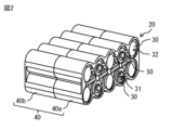
- FIG. 2 is a perspective view illustrating an example of the configuration of a battery module accommodated in the battery pack of FIG.
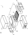
- FIG. 3 is a perspective view showing an example of the structure of the battery pack shown in FIG. 1 in an exploded view.
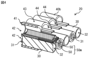
- FIG. 4 is a diagram illustrating an example of a cross-sectional configuration of the battery module of FIG.
- FIG. 5 is a perspective view illustrating an example of the heat absorption module of FIG.
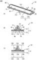
- Fig. 6A is a perspective view showing an example of the heat absorbing member shown in Fig. 5.
- Figs. 6B and 6C are cross-sectional views showing an example of the heat absorbing member shown in Fig.
- FIG. 6A taken along line A-A. 7A and 7B are enlarged views showing an example of a cross-sectional configuration of a portion of FIG. 6B.
- FIG. 8 is an enlarged perspective view illustrating an example of a configuration of a portion of the heat absorbing member of FIG.
- FIG. 9 is an enlarged cross-sectional view of a portion of the battery module of FIG.
- FIG. 10 is a diagram showing an example of a manufacturing process for the heat absorbing member of FIG.
- Fig. 11(A) is a diagram showing a modified example of the cross-sectional configuration of the heat absorbing member shown in Fig. 7(A).
- Fig. 11(B) is a diagram showing a modified example of the cross-sectional configuration of the heat absorbing member shown in Fig. 7(B).
- Fig. 12(A) is a perspective view showing a modified example of the heat absorbing member shown in Fig. 6(A).
- Fig. 12(B) and Fig. 12(C) are cross-sectional views showing an example of the heat absorbing member shown in Fig. 12(A) taken along line A-A.
- 13A and 13B are enlarged views showing an example of a cross-sectional configuration of a portion of FIG. 12B.
- FIG. 14 is an enlarged perspective view illustrating an example of a configuration of a portion of the heat absorbing member of FIG.
- FIG. 15 is a diagram showing an example of a manufacturing process for the heat absorbing member of FIG.
- FIG. 16 is a perspective view illustrating a modified example of the heat absorbing member shown in FIG. FIG.
- FIG. 17 is a perspective view illustrating a modified example of the heat absorbing member shown in FIG.
- FIG. 18 is a perspective view illustrating a modified example of the heat absorbing member shown in FIG. 19A to 19C are diagrams illustrating an example of a manufacturing process for the heat absorbing member of FIG. 18.
- FIG. 20 is a perspective view illustrating a modification of the heat absorbing member of FIG. 21A to 21C are diagrams illustrating an example of a manufacturing process for the heat absorbing member of FIG. 20.
- FIG. 20 is a perspective view illustrating a modification of the heat absorbing member of FIG. 21A to 21C are diagrams illustrating an example of a manufacturing process for the heat absorbing member of FIG. 20.
- the battery pack described here is a power source comprising multiple batteries, and is applicable to a variety of uses, such as electronic devices. Uses of the battery pack will be described in detail below.
- the type of battery is not particularly limited, and may be a primary battery or a secondary battery.
- the type of secondary battery is not particularly limited, but specifically may be a lithium ion secondary battery, which obtains battery capacity by utilizing the absorption and release of lithium ions.
- the number of batteries is not particularly limited, and may be set as desired. Below, a case will be described in which the battery is a secondary battery (lithium ion secondary battery).
- the battery pack described below is a power source comprising multiple secondary batteries.
- FIG. 1 shows an example of a perspective configuration of a battery pack 1 according to an embodiment of the present technology.
- FIG. 2 shows an example of a perspective configuration of a battery module 20 housed in the battery pack 1.
- FIG. 3 shows an example of an expanded perspective configuration of the battery pack 1.
- FIG. 4 shows an example of a cross-sectional configuration of the battery module 20.
- the battery pack 1 comprises an exterior case 10, a battery module 20, a number of metal tabs 60, and a control board 70.
- the control board 70 is connected to the positive and negative terminals of the battery module 20 via the number of metal tabs 60, for example, and has circuits that measure the voltage of the battery and the battery module 20, detect the remaining capacity of the battery module 20, and measure the current output from the battery module 20 to detect the presence or absence of an overcurrent.
- the exterior case 10 houses the battery module 20, the multiple metal tabs 60, and the control board 70.
- the exterior case 10 is composed of a lower case 10a and an upper case 10b.
- the lower case 10a and the upper case 10b are stacked on top of each other to form a storage space that houses the battery module 20, the multiple metal tabs 60, and the control board 70.
- the exterior case 10 (for example, the lower case 10a) is provided with an external terminal 11 connected to the control board 70.
- the battery module 20 is connected to the external terminal 11 via the control board 70.
- the battery pack 1 has a discharge mode in which it supplies power output from the battery module 20 to a load via the external terminal 11.
- the battery pack 1 may further have a charge mode in which it accumulates power supplied via the external terminal 11 from a power source connected to the external terminal 11 in the battery module 20.
- the control board 70 is configured to switch between the discharge mode and the charge mode depending on the type of connected object connected to the external terminal 11.
- the control board 70 is configured to execute only the discharge mode.
- the battery module 20 has a plurality of batteries 30, for example, as shown in Figures 2 and 3.
- the plurality of batteries 30 are electrically connected via a plurality of metal tabs 60.
- Each battery 30 has a positive electrode 31 and a negative electrode 32, for example, as shown in Figure 2.
- Each battery 30 is, for example, a cylindrical battery in which the positive electrode 31 and the negative electrode 32 extend in a direction facing each other.
- some of the plurality of batteries 30 are connected in series with each other by a plurality of metal tabs 60, and when the plurality of batteries 30 connected in series with each other are referred to as a series unit, the plurality of series units are connected in parallel with each other by a plurality of metal tabs 60.
- the connection mode of the plurality of batteries 30 is not limited to the above.
- Each metal tab 60 is, for example, composed of a metal lead plate.
- Each battery 30 is a primary battery or a secondary battery.
- the type of secondary battery is not particularly limited, but specifically, it is a lithium ion secondary battery that obtains battery capacity by utilizing the absorption and release of lithium ions.
- each battery 30 is a secondary battery (lithium ion secondary battery).
- the battery pack 1 described below is a power source equipped with multiple secondary batteries.
- the battery module 20 further includes a battery holder 40 that supports the multiple batteries 30, and multiple heat absorption members 50 arranged between the multiple batteries 30, as shown in Figures 2 and 3, for example.
- the battery holder 40 has a structure that supports the multiple batteries 30 in a hierarchical manner with a predetermined gap between them.
- the heat absorption members 50 will be described in detail later.
- FIG. 4 shows an example of the cross-sectional configuration of the battery module 20.
- the battery holder 40 is composed of a pair of holders 40a and 40b, as shown in FIG. 3 and FIG. 4. Both holders 40a and 40b have a common structure.
- Each of the holders 40a and 40b has a side plate portion 41, for example as shown in FIG. 4.
- the side plate portion 41 of the holder 40a and the side plate portion 41 of the holder 40b are arranged opposite each other with the batteries 30 between them in the extension direction of each battery 30 (the direction in which the positive electrodes 31 and negative electrodes 32 face each other).
- the side plate portion 41 has an opening 42 at a position facing the positive electrode 31 and negative electrode 32 of each battery 30. Therefore, the positive electrode 31 or negative electrode 32 is exposed in the opening 42.
- Each of the holders 40a and 40b further has a support section 43 that supports a plurality of batteries 30 in a hierarchical manner with a predetermined gap therebetween, for example, as shown in FIG. 4.
- a side plate section 41 is connected to each end of the support section 43.
- the support section 43 supports four or more cylindrical batteries 30 in a hierarchical manner with a predetermined gap therebetween.
- the support section 43 has an opening 44 at a location surrounded by four adjacent cylindrical batteries 30, for example, as shown in FIG. 4.
- a heat absorption module 50m consisting of two overlapping heat absorption members 50 is arranged at a position surrounded by four adjacent cylindrical batteries 30, for example, as shown in FIG. 4 and FIG. 5, and contacts the outer circumferential surfaces of the four cylindrical batteries 30 through the opening 44.
- the heat absorption module 50m extends in a direction parallel to the extension direction of each battery 30 (the direction in which the positive electrode 31 and the negative electrode 32 face each other).
- Each heat absorption member 50 constituting the heat absorption module 50m also extends in a direction parallel to the extension direction of each battery 30 (the direction in which the positive electrode 31 and the negative electrode 32 face each other).
- one heat absorption member 50 contacts the outer peripheral surface of two batteries 30 arranged in the upper row of the four adjacent cylindrical batteries 30, and the other heat absorption member 50 contacts the outer peripheral surface of two batteries 30 arranged in the lower row of the four adjacent cylindrical batteries 30.
- the flat surfaces flat surface S4 described below (see FIG.
- the opening 44 contacts the side plate portion 41 of the holder 40a and the side plate portion 41 of the holder 40b, and the heat absorption member 50 contacts the side plate portion 41 of the holder 40a and the side plate portion 41 of the holder 40b through the opening 44.
- Fig. 6(A) shows an example of a perspective configuration of the heat absorbing member 50.
- Fig. 6(B) and Fig. 6(C) show an example of a cross-sectional configuration of the heat absorbing member 50 taken along line A-A.
- Fig. 6(B) mainly lists reference numbers for the shape of the container 51, and
- Fig. 6(C) mainly lists reference numbers for the storage portion and flange portion of the container 51.
- the heat absorption member 50 has a shape corresponding to the shape of the gaps between the multiple batteries 30 supported by the battery holder 40 (supporting portion 43).
- the heat absorption member 50 has a long and thin columnar shape.
- a heat absorption module 50m consisting of two overlapping heat absorption members 50 contacts the surfaces (outer peripheral surfaces) of the four adjacent cylindrical batteries 30, and has a shape corresponding to the shape of the gaps between the four adjacent cylindrical batteries 30, for example.
- the cross section perpendicular to the extension direction of the heat absorption module 50m is approximately rhombus-shaped.
- the cross section perpendicular to the extension direction of the heat absorption member 50 is approximately triangular-shaped.
- the two adjacent cylindrical batteries 30 are referred to as the first battery 30 and the second battery 30.
- the heat absorption member 50 has an arc wall W1 (arc surface S1) extending along the outer circumferential surface of the first battery 30, and an arc wall W2 (arc surface S2) extending along the outer circumferential surface of the second battery 30.
- the arc wall W2 is disposed in a position adjacent to the arc wall W1.
- the two arc walls W1, W2 (or the two arc surfaces S1, S2) have a concave shape following the outer circumferential surface of the battery 30.
- the heat absorption member 50 further has end walls W3 constituting part of the longitudinal ends of the heat absorption member 50 at both longitudinal ends of the heat absorption member 50, and has a flat wall W4 (flat surface S4) at a location facing the arc walls W1, W2 via the heat absorption agent 54 described later. End wall W3 is positioned adjacent to both arc walls W1 and W2.
- the heat absorbing member 50 has a heat absorbing agent 54 and a container 51 that covers the heat absorbing agent 54, for example, as shown in Figures 6(B) and 6(C).
- Container 51 covers heat absorbing agent 54.
- Container 51 is formed, for example, by filling a container made of two laminates 52, 53 that are heat fused together except for one side with heat absorbing agent 54, and then heat fusion of the remaining side, which is the filling port, after filling.
- container 51 contains heat absorbing agent 54.
- Laminate 52 corresponds to a specific example of a "first container part" according to an embodiment of the present technology.
- Laminate 53 corresponds to a specific example of a "second container part” according to an embodiment of the present technology.
- the container 51 has a storage section 51A that stores a heat absorbing agent 54, and a flange section 51B formed around the storage section 51A.
- the storage section 51A corresponds to a roughly triangular prism-shaped section of the container 51 that is made up of the arc walls W1 and W2, the end wall W3, and a part of the flat wall W4.
- the flange section 51B corresponds to a plate-shaped section of the container 51 that is formed to surround the storage section 51A when viewed from the normal direction of the flat wall W4.
- the laminate 52 has a first accommodation portion 52A constituting a part of the accommodation portion 51A, and a first flange portion 52B constituting a part of the flange portion 51B.
- the first accommodation portion 52A corresponds to the portion constituted by the arc walls W1, W2 and the end wall W3.
- the first accommodation portion 52A and the first flange portion 52B are integrally formed with each other, and the laminate 52 is connected to the second flange portion 53B described below at the first flange portion 52B.
- the laminate 53 has a second accommodation portion 53A constituting a part of the accommodation portion 51A, and a second flange portion 53B constituting a part of the flange portion 51B.
- the second accommodation portion 53A corresponds to the portion constituted by a part of the flat wall W4.
- the second accommodation portion 53A and the second flange portion 53B are integrally formed with each other, and the laminate 53 is connected to the first flange portion 52B at the second flange portion 53B.
- the first storage section 52A corresponds to a specific example of a "first storage section” according to an embodiment of the present technology.
- the first flange section 52B corresponds to a specific example of a "first flange section” according to an embodiment of the present technology.
- the second storage section 53A corresponds to a specific example of a "second storage section” according to an embodiment of the present technology.
- the second flange section 53B corresponds to a specific example of a "second flange section” according to an embodiment of the present technology.
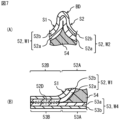
- FIG. 7(A) and 7(B) are enlarged views of an example of a cross-sectional configuration of a portion of FIG. 6(B).
- FIG. 7(A) shows an enlarged view of the boundary between the arc wall W1 and the arc wall W2.
- FIG. 7(B) shows an enlarged view of the portion where the laminate 52 and the laminate 53 are connected to each other.
- the laminate 52, the first storage section 52A, and the first flange section 52B are configured to include a resin layer 52a, for example, as shown in FIG. 7(A) and FIG. 7(B).
- the laminate 53, the second storage section 53A, and the second flange section 53B are configured to include a resin layer 53a, for example, as shown in FIG. 7(A) and FIG. 7(B).
- the resin layers 52a and 53a are configured to include a resin material such as polyethylene, polystyrene, polypropylene, polycarbonate, etc.
- the laminate 52, the first storage section 52A, and the first flange section 52B may be made of, for example, a laminate film.
- the laminate 52, the first storage section 52A, and the first flange section 52B are made of, for example, a resin layer 52a and a metal layer 52b in this order from the heat absorbing agent 54 side, as shown in Figures 7(A) and 7(B).
- the laminate 52, the first storage section 52A, and the first flange section 52B are made of, for example, a resin layer 52a.
- the metal layer 52b is made of, for example, a metal foil such as aluminum foil.
- the laminate 53, the second storage section 53A, and the second flange section 53B may be made of, for example, a laminate film.
- the laminate 53, the second storage section 53A, and the second flange section 53B are made of, for example, a resin layer 53a and a metal layer 53b in this order from the heat absorbing agent 54 side, as shown in Figures 7(A) and 7(B).
- the laminate 53, the second storage section 53A, and the second flange section 53B are made of, for example, a resin layer 53a.
- the metal layer 53b is made of, for example, a metal foil such as aluminum foil.
- the heat absorbing agent 54 is composed of, for example, a liquid containing water or a hydrogel.
- a hydrogel As the heat absorbing agent 161, it is preferable to use a synthetic polymer gel.
- materials for the synthetic polymer gel include sodium polyacrylate (PNaAA), polyvinyl alcohol (PVA), polyhydroxyethyl methacrylate (PHE-MA), and silicone hydrogel.
- the laminate 52 has a shape bent at an acute angle at the boundary BD between the arc wall W1 and the arc wall W2, as shown in FIG. 7(A).
- the laminate 52 and the laminate 53 are welded to each other, as shown in FIG. 7(B), and a part of the resin layer 52a of the laminate 52 and a part of the resin layer 53a of the laminate 53 are welded to each other.
- the part where the part of the resin layer 52a of the laminate 52 and a part of the resin layer 53a of the laminate 53 are welded to each other is the welded part 52D.
- the first flange portion 52B and the second flange portion 53B are welded to each other, as shown in FIG. 7(B), and a part of the resin layer 52a of the first flange portion 52B and a part of the resin layer 53a of the second flange portion 53B are welded to each other.
- the portion where a portion of the resin layer 52a of the first flange portion 52B and a portion of the resin layer 53a of the second flange portion 53B are welded to each other is the welded portion 52D.
- the welded portion 52D penetrates in the lamination plane direction of the flange portion 51B, for example, as shown in FIG. 7(B). Therefore, when the welded portion 52D in the flange portion 51B is heated, for example, by the heat of a battery 30 that is abnormally generating heat, the welded portion 52D peels off due to the heat, connecting the storage space of the storage portion 51A to the outside. As a result, the heat-absorbing agent 54 leaks out through the end of the flange portion 51B to the outside (for example, the peripheral surface of the battery 30 that is abnormally generating heat). Therefore, the welded portion 52D functions as a peelable portion that can peel off due to heating, connecting the storage space of the storage portion 51A to the outside.
- the welded portion 52D may not be exposed to the end face of the flange portion 51B.
- the resin layer 52a of the laminate 52 and the resin layer 53a of the laminate 53 may be in physical contact between the end face of the flange portion 51B and the welded portion 52D, and may be peelable without heating.
- the resin layer 52a of the laminate 52 and the resin layer 53a of the laminate 53 may be in contact with an adhesive between the end face of the flange portion 51B and the welded portion 52D.
- the welded portion 52D may not be exposed to the storage space of the storage portion 51A.
- the resin layer 52a of the laminate 52 and the resin layer 53a of the laminate 53 may be in physical contact between the welded portion 52D and the storage space of the storage portion 51A, and may be peelable without heating.
- the resin layer 52a of the laminate 52 and the resin layer 53a of the laminate 53 may be in contact with an adhesive between the welded portion 52D and the storage space of the storage portion 51A.
- the welded portion 52D in the flange portion 51B is heated, for example, by the heat of the abnormally heated battery 30, the welded portion 52D is peeled off by heating, and the storage space of the storage portion 51A is connected to the outside.
- the heat absorbing agent 54 leaks out to the outside (for example, the periphery of the abnormally heated battery 30) through the end of the flange portion 51B. Therefore, the welded portion 52D functions as a peelable portion that can be peeled off by heating to connect the storage space of the storage portion 51A to the outside.
- FIG. 8 is an enlarged perspective view of a portion of the heat absorption member 50 in FIG. 6(A).
- FIG. 9 is an enlarged cross-sectional view of a portion of the battery module 20 in FIG. 2.
- FIG. 9 shows a cross-sectional view including a cutout 51C, which will be described later.
- the container 51 has one or more cutouts 51C, as shown in FIG. 6(A) and FIG. 8.
- Each cutout 51C is provided in the flange 51B.
- the bonded portion (welded portion 52D) of the first flange 52B and the second flange 53B has a portion (narrowed region R1) where the width Da of the bonded portion (welded portion 52D) is locally narrower than the width Db of the flange 51B.
- the width Db of the flange portion 51B refers to the width of the plate-shaped portion of the laminate 52, 53, and more specifically, refers to the width of the plate-shaped portion of the laminate 52, 53 on the side where the narrow region R1 exists. Note that FIG. 8 illustrates an example in which the maximum value of the width Da of the welded portion 52D is equal to the width Db of the flange portion 51B.
- Each cutout 51C is formed to penetrate the laminates 52, 53.
- Each cutout 51C is formed to penetrate the adhesive portion (welded portion 52D) between the resin layer 52a of the first flange portion 52B and the resin layer 53a of the second flange portion 53B.
- Each cutout 51C is provided adjacent to the welded portion 52D.
- Each cutout 51C may have an acute corner that protrudes toward the storage space ⁇ of the storage portion 51A when viewed from a direction in which the entire flange portion 51B can be seen, for example, as shown in FIG. 8. In this case, a narrow region R1 may be formed adjacent to this acute corner.
- Each cutout portion 51C is disposed at a position adjacent to two adjacent batteries 30, for example, as shown in FIG. 9.
- Each cutout portion 51C is disposed in a central region of the heat absorption member 50 in the longitudinal direction of the heat absorption member 50, for example, as shown in FIG. 6(A).
- the "central region” refers to, for example, a region of the flange portion 51B that is away from the end wall W3 by a length equal to or greater than the height of the end wall W3.
- FIG. 10 shows an example of the manufacturing process of the heat absorbing member 50.
- the laminate 52' formed into a mountain shape by drawing and the flat laminate 53' are overlapped.
- the mold pieces Ma and Mb are pressed against the flange portion of the laminate 52', while the laminate 53' is supported by a flat mold piece Mc, and each mold piece Ma and Mb is heated to a predetermined temperature (FIG. 10).
- the heat of each mold piece Ma and Mb is transmitted to the resin layers 52a and 53a in the laminates 52' and 53', and a part of the resin layers 52a and 53a is welded to form the welded portion 52D.
- the laminates 52' and 53' become container-shaped.
- the mold pieces Ma, Mb, and Mc are detached from the laminates 52' and 53'.
- the heat absorbing agent 54 is filled into the container in which the laminates 52', 53' are heat-sealed except for one side, and the remaining side, which is the filling port, is heat-sealed after filling.
- one or more notches 51C are formed in predetermined locations of the laminates 52', 53'. In this manner, the heat absorbing member 50 is manufactured.
- a heat absorbing member is in contact with the side of the battery unit, and the heat absorbing member contains a heat absorbing agent (gel-like fluid) inside an exterior film (see, for example, Patent Document 1).
- a notch 51C is provided in the container 51 of the heat absorption member 50 arranged in a position adjacent to the battery 30. This allows the heat absorption agent 54 leaking to the outside through the notch 51C to come into contact with the abnormally heated battery 30, thereby cooling the abnormally heated battery 30.
- the notch 51C in a desired location on the container 51, the abnormally heated battery 30 can be effectively cooled. Therefore, the abnormally heated battery 30 can be sufficiently cooled by the heat absorption member 50.
- the width Da of the adhesive portion (welded portion 52D) of the first flange portion 52B and the second flange portion 53B is locally narrower than the width Db of the flange portion 51B.
- the width Da of the welded portion 52D is locally narrowed by the cutout portion 51C.
- the heat absorbing agent 54 leaks out to the outside (for example, the peripheral surface of the abnormally heated battery 30) through the end of the flange portion 51B, and the leaked heat absorbing agent 54 comes into contact with the abnormally heated battery 30 and can cool the abnormally heated battery 30. Therefore, by providing the cutout portion 51C at a desired location on the container 51, the abnormally heated battery 30 can be effectively cooled. From the above, the abnormally heated battery 30 can be sufficiently cooled by the heat absorbing member 50.
- the first storage section 52A and the second storage section 53A are shaped so that the exterior of the storage section 51A is approximately triangular prism-shaped.
- the portion of the laminate 52 corresponding to the first flange portion 52B and the portion of the laminate 53 corresponding to the second flange portion 53B are bonded to each other.
- the cutout portion 51C is formed to penetrate the laminates 52 and 53.
- the heat absorbing agent 54 leaks out to the outside (for example, the periphery of the abnormally heated battery 30) through the end of the flange portion 51B, and the leaked heat absorbing agent 54 comes into contact with the abnormally heated battery 30 and can cool the abnormally heated battery 30. Therefore, by providing the cutout portion 51C at a desired location of the container 51, the abnormally heated battery 30 can be effectively cooled. From the above, the abnormally heated battery 30 can be sufficiently cooled by the heat absorbing member 50.
- the resin layer 52a of the first flange portion 52B and the resin layer 53a of the second flange portion 53B are welded to each other, and the cutout portion 51C is formed to penetrate the welded portion 52D between the resin layer 52a of the first flange portion 52B and the resin layer 53a of the second flange portion 53B.
- the narrow area R1 of the welded portion 52D caused by the cutout portion 51C is peeled off first due to the heat, and the storage space of the storage portion 51A is connected to the outside.
- the heat absorbing agent 54 leaks out to the outside (for example, the periphery of the abnormally heated battery 30) through the end of the flange portion 51B, and the leaked heat absorbing agent 54 comes into contact with the abnormally heated battery 30 and can cool the abnormally heated battery 30. Therefore, by providing the cutout portion 51C at a desired location on the container 51, the abnormally heated battery 30 can be effectively cooled. From the above, the abnormally heated battery 30 can be sufficiently cooled by the heat absorbing member 50.
- the cutout portion 51C is disposed at a position adjacent to two adjacent batteries 30.
- the cutout portion 51C is disposed in the central region of the heat absorption member 50 in the longitudinal direction of the heat absorption member 50.
- the heat absorption agent 54 leaks out to the outside (for example, the peripheral surface of the battery 30 that is abnormally heated) through the end of the flange portion 51B, and the leaked heat absorption agent 54 comes into contact with the abnormally heated battery 30 and can cool the abnormally heated battery 30. Therefore, by providing the cutout portion 51C at a desired location of the container 51, the abnormally heated battery 30 can be effectively cooled. From the above, the abnormally heated battery 30 can be sufficiently cooled by the heat absorption member 50.
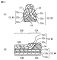
- FIG. 11(A) shows a modified example of the cross-sectional structure of the heat absorbing member of FIG. 7(A).
- FIG. 11(B) shows a modified example of the cross-sectional structure of the heat absorbing member of FIG. 7(B).
- the laminate 52 may have a configuration in which the metal layer 52b is sandwiched between the resin layers 52a and 52c, as shown in FIG. 11(A) and FIG. 11(B).
- the laminate 53 may have a configuration in which the metal layer 53b is sandwiched between the resin layers 53a and 53c, as shown in FIG. 11(B).
- the resin layers 52c and 53c are made of a resin material such as polyethylene, polystyrene, polypropylene, and polycarbonate.
- the cutout portion 51C penetrates the resin layers 52c and 53c.
- the metal layer 52b is coated with the resin layer 52c
- the metal layer 53b is coated with the resin layer 53c, so that it is possible to more reliably prevent the metal layers 52b, 53b from shorting out with the conductors within the battery module 20.
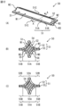
- Fig. 12(A) shows a modified example of the perspective configuration of the heat absorbing member of Fig. 6(A).
- Fig. 12(B) and Fig. 12(C) show an example of the cross-sectional configuration of the heat absorbing member of Fig. 12(A) taken along line A-A.
- Fig. 12(B) mainly shows reference characters for the shape of the container 51, and
- Fig. 12(C) mainly shows reference characters for the housing portion and flange portion of the container 51.
- the heat absorption member 50 has a shape corresponding to the shape of the gaps between the multiple batteries 30 supported by the battery holder 40 (supporting portion 43).
- the heat absorption member 50 has a long and thin columnar shape, like the batteries 30.
- the heat absorption member 50 is in contact with the surfaces (outer peripheral surfaces) of the four adjacent cylindrical batteries 30, and has a shape corresponding to the shape of the gaps between the four adjacent cylindrical batteries 30, for example.
- the cross section of the heat absorption member 50 perpendicular to the extension direction is approximately diamond shaped. In this case, for example, as shown in FIG. 12(B), the cross section of the heat absorption member 50 perpendicular to the extension direction is approximately diamond shaped.
- the two adjacent cylindrical batteries 30 are referred to as the first battery 30 and the second battery 30.
- the heat absorption member 50 has an arc wall W1 (arc surface S1) that extends along the outer circumferential surface of the first battery 30, and an arc wall W2 (arc surface S2) that extends along the outer circumferential surface of the second battery 30.
- the arc wall W2 is disposed in a position adjacent to the arc wall W1.
- the two arc walls W1, W2 (or the two arc surfaces S1, S2) have a concave shape that follows the outer circumferential surface of the battery 30.
- the two adjacent cylindrical batteries 30 are referred to as the third battery 30 and the fourth battery 30.
- the heat absorption member 50 has an arc wall W5 (arc surface S5) that extends along the outer circumferential surface of the third battery 30, and an arc wall W6 (arc surface S6) that extends along the outer circumferential surface of the fourth battery 30.
- the arc wall W6 is disposed in a position adjacent to the arc wall W5.
- the two arc walls W5, W6 (or the two arc surfaces S5, S6) have a concave shape that follows the outer circumferential surface of the battery 30.
- the heat absorbing member 50 further has end walls W3 at both longitudinal ends of the heat absorbing member 50, which constitute part of the longitudinal ends of the heat absorbing member 50.
- the end walls W3 are disposed adjacent to both of the arc walls W1 and W2.
- the end walls W3 are further disposed adjacent to both of the arc walls W5 and W6.
- the heat absorbing member 50 has a heat absorbing agent 54 and a container 51 that covers the heat absorbing agent 54, for example, as shown in Figures 12(B) and 12(C).
- the container 51 covers the heat absorbing agent 54.
- the container 51 is formed, for example, by heating and molding the heat absorbing agent 54 and the laminates 52 and 55 in a state where the heat absorbing agent 54 is covered with the laminates 52 and 55. Therefore, the container 51 contains the heat absorbing agent 54.
- the container 51 has a storage section 51A that stores a heat absorbing agent 54, and a flange section 51B formed around the storage section 51A.
- the storage section 51A corresponds to the roughly diamond-shaped columnar section of the container 51 that is made up of the arc walls W1 and W2, the end wall W3, and the arc walls W5 and W6.
- the flange section 51B corresponds to the plate-shaped section of the container 51 that is formed to surround the storage section 51A when viewed from a direction in which the entire arc walls W1 and W2 can be seen.
- the laminate 52 has a first storage portion 52A constituting a part of the storage portion 51A, and a first flange portion 52B constituting a part of the flange portion 51B.
- the first storage portion 52A corresponds to the portion constituted by the arc walls W1, W2 and the end wall W3.
- the first storage portion 52A and the first flange portion 52B are formed integrally with each other, and the laminate 52 is connected to the second flange portion 53B described below at the flange portion 51B.
- the laminate 55 has a third storage portion 55A constituting a part of the storage portion 51A, and a third flange portion 55B constituting a part of the flange portion 51B.
- the third storage portion 55A corresponds to the portion constituted by the arc walls W5, W6 and the end wall W3.
- the third storage portion 55A and the third flange portion 55B are formed integrally with each other, and the laminate 55 is connected to the first flange portion 52B at the flange portion 51B.
- FIG. 13(A) and 13(B) are enlarged views of an example of a cross-sectional configuration of a portion of FIG. 12(B).
- FIG. 13(A) shows an enlarged view of the boundary BD between the arc wall W5 and the arc wall W6.
- FIG. 13(B) shows an enlarged view of a portion where the laminate 52 and the laminate 55 are connected to each other.
- the laminate 55, the third storage section 55A, and the third flange section 55B are configured to include a resin layer 55a, for example, as shown in FIG. 13(A) and FIG. 13(B).
- the laminate 55, the third storage section 55A, and the third flange section 55B are configured to include a resin layer 55a, for example, as shown in FIG. 13(A) and FIG. 13(B).
- the resin layer 55a is configured to include a resin material such as polyethylene, polystyrene, polypropylene, polycarbonate, etc.
- the laminate 55, the third storage section 55A, and the third flange section 55B may be made of, for example, a laminate film.
- the laminate 55, the third storage section 55A, and the third flange section 55B are made of, for example, a resin layer 55a and a metal layer 55b in this order from the heat absorbing agent 54 side, as shown in Figures 13(A) and 13(B).
- the laminate 55, the third storage section 55A, and the third flange section 55B are made of, for example, a resin layer 55a.
- the metal layer 55b is made of, for example, a metal foil such as aluminum foil.
- the laminate 55 has a shape bent at an acute angle at the boundary BD between the arc walls W5 and W6, as shown in FIG. 13(A), for example.
- a part of the resin layer 52a of the arc wall W5 and a part of the resin layer 52a of the arc wall W6 are welded to each other, as shown in FIG. 13(A), for example.
- the part where the part of the resin layer 52a of the arc wall W5 and the part of the resin layer 52a of the arc wall W6 are welded to each other is the welded part 52D in FIG. 13(A).
- the laminate 52 and the laminate 55 are welded to each other, as shown in FIG. 13(B), for example.
- the laminate 52 and the laminate 55 are welded to each other, and a part of the resin layer 52a of the laminate 52 and a part of the resin layer 55a of the laminate 55 are welded to each other.
- a portion where a part of the resin layer 52a of the laminate 52 and a part of the resin layer 53a of the laminate 55 are welded to each other is the welded portion 52D.
- the flange portion 51B for example, as shown in FIG.
- the first flange portion 52B and the third flange portion 55B are welded to each other, and a part of the resin layer 52a of the first flange portion 52B and a part of the resin layer 55a of the third flange portion 55B are welded to each other.
- a portion where a part of the resin layer 52a of the first flange portion 52B and a part of the resin layer 55a of the third flange portion 55B are welded to each other is the welded portion 52D.
- the welded portion 52D is exposed on the end surface of the flange portion 51B. Furthermore, the welded portion 52D exposes the storage space of the storage portion 51A. That is, the welded portion 52D penetrates the flange portion 51B in the lamination plane direction of the flange portion 51B. Therefore, when the welded portion 52D in the flange portion 51B is heated by, for example, the heat of the battery 30 that is abnormally heated, the welded portion 52D peels off due to heating, and the storage space of the storage portion 51A communicates with the outside.
- the heat absorbing agent 54 leaks out to the outside (for example, the peripheral surface of the battery 30 that is abnormally heated) through the end of the flange portion 51B. Therefore, the welded portion 52D functions as a peelable portion that can be peeled off due to heating to communicate the storage space of the storage portion 51A with the outside.
- the welded portion 52D may not be exposed on the end face of the flange portion 51B. However, in this case, the resin layer 52a of the laminate 52 and the resin layer 55a of the laminate 55 may be in physical contact between the end face of the flange portion 51B and the welded portion 52D, and the welded portion 52D may be peelable without heating. The welded portion 52D may not be exposed to the storage space of the storage portion 51A. However, in this case, the resin layer 52a of the laminate 52 and the resin layer 55a of the laminate 55 may be in physical contact between the welded portion 52D and the storage space of the storage portion 51A, and the welded portion 52D may be peelable without heating.
- the welded portion 52D in the flange portion 51B is heated, for example, by the heat of a battery 30 that is abnormally hot, the welded portion 52D peels off due to heating, and the storage space of the storage portion 51A communicates with the outside.
- the heat absorbing agent 54 leaks out through the end of the flange portion 51B to the outside (for example, to the periphery of the abnormally heated battery 30). Therefore, the welded portion 52D functions as a peelable portion that can be peeled off by heating to connect the storage space of the storage portion 51A to the outside.
- FIG. 14 is an enlarged perspective view of a portion of the heat absorbing member 50 of FIG. 12(A).
- the container 51 is provided with one or more notches 51C, as shown in FIG. 12(A) and FIG. 14.
- Each notch 51C is provided in the flange 51B.
- the welded portion 52D has a portion (narrowed region R1) where the width Da of the welded portion 52D is locally narrower than the width Db of the flange 51B.
- the width Db of the flange 51B refers to the width of the plate-like portion of the laminate 52, 55, and more specifically, refers to the width of the plate-like portion of the laminate 52, 55 on the side where the narrowed region R1 exists.
- FIG. 14 illustrates an example in which the maximum value of the width Da of the welded portion 52D is equal to the width Db of the flange 51B.
- Each cutout 51C is formed to penetrate the laminate 52, 55. Each cutout 51C is formed to penetrate the welded portion 52D. Each cutout 51C is provided adjacent to the welded portion 52D. For example, as shown in FIG. 14, each cutout 51C may have an acute corner that protrudes toward the storage space ⁇ of the storage portion 51A when viewed from a direction in which the entire flange portion 51B can be seen. In this case, a narrow region R1 may be formed adjacent to this acute corner.
- Each cutout portion 51C is disposed at a position adjacent to two adjacent batteries 30.
- each cutout portion 51C is disposed in the central region of the heat absorption member 50 in the longitudinal direction of the heat absorption member 50.
- the "central region” refers to, for example, a region of the flange portion 51B that is away from the end wall W3 by a length equal to or greater than the height of the end wall W3.
- FIG. 15 shows an example of the manufacturing process of the heat absorbing member 50.
- the laminates 52' and 55' formed into a mountain shape by drawing are stacked together.
- the mold pieces Ma and Mb are pressed against the flange portion of the laminate 52', and the mold pieces Md and Me are pressed against the flange portion of the laminate 55', and each mold piece Ma, Mb, Md, and Me is heated to a predetermined temperature (FIG. 15).
- each mold piece Ma, Mb, Md, and Me is transmitted to the resin layers 52a and 55a in the laminates 52' and 55', and a part of the resin layers 52a and 55a is welded to form the welded portion 55D.
- one side is not fused and the remaining side is fused.
- the laminates 52' and 55' become container-shaped.
- each mold piece Ma, Mb, Md, and Me are removed from the laminates 52', 55'.
- the laminates 52', 55' are heat-sealed except for one side in a container, which is filled with heat-absorbing agent 54, and after filling, the filling port, which is the remaining side, is heat-sealed.
- one or more notches 51C are formed in predetermined locations of the laminates 52', 55'. In this manner, the heat-absorbing member 50 is manufactured.
- a notch 51C is provided in the container 51 of the heat absorption member 50 arranged in a position adjacent to the battery 30. This allows the heat absorption agent 54 leaking to the outside through the notch 51C to come into contact with the abnormally heated battery 30, thereby cooling the abnormally heated battery 30.
- the notch 51C in a desired location on the container 51, the abnormally heated battery 30 can be effectively cooled. Therefore, the abnormally heated battery 30 can be sufficiently cooled by the heat absorption member 50.
- the width Da of the adhesive portion (welded portion 52D) of the first flange portion 52B and the third flange portion 55B is locally narrower than the width Db of the flange portion 51B.
- the width Da of the welded portion 52D is locally narrowed by the cutout portion 51C.
- the heat absorbing agent 54 leaks out to the outside (for example, the periphery of the abnormally heated battery 30) through the end of the flange portion 51B, and the leaked heat absorbing agent 54 comes into contact with the abnormally heated battery 30 and can cool the abnormally heated battery 30. Therefore, by providing the cutout portion 51C at a desired location on the container 51, the abnormally heated battery 30 can be effectively cooled. From the above, the abnormally heated battery 30 can be sufficiently cooled by the heat absorbing member 50.
- the first storage section 52A and the third storage section 55A are shaped so that the exterior of the storage section 51A is a roughly diamond-shaped column. This allows the heat absorption member 50 to come into contact with the outer periphery of the four cylindrical batteries 30 when the heat absorption member 50 is placed in a position surrounded by four adjacent cylindrical batteries 30. As a result, the leaked heat absorption agent 54 comes into contact with the abnormally heated battery 30, and the abnormally heated battery 30 can be cooled. Therefore, by providing a notch 51C at a desired location on the container 51, the abnormally heated battery 30 can be effectively cooled. From the above, the abnormally heated battery 30 can be sufficiently cooled by the heat absorption member 50.
- the portion of the laminate 52 corresponding to the first flange portion 52B and the portion of the laminate 55 corresponding to the third flange portion 55B are bonded to each other.
- the cutout portion 51C is formed to penetrate the laminates 52 and 55.
- the heat absorbing agent 54 leaks out to the outside (for example, the periphery of the abnormally heated battery 30) through the end of the flange portion 51B, and the leaked heat absorbing agent 54 comes into contact with the abnormally heated battery 30 and can cool the abnormally heated battery 30. Therefore, by providing the cutout portion 51C at a desired location of the container 51, the abnormally heated battery 30 can be effectively cooled. From the above, the abnormally heated battery 30 can be sufficiently cooled by the heat absorbing member 50.
- the resin layer 52a of the first flange portion 52B and the resin layer 55a of the third flange portion 55B are welded to each other, and the cutout portion 51C is formed to penetrate the welded portion 52D between the resin layer 52a of the first flange portion 52B and the resin layer 55a of the third flange portion 55B.
- the narrow area R1 of the welded portion 52D caused by the cutout portion 51C is peeled off first due to the heat, and the storage space of the storage portion 51A is connected to the outside.
- the heat absorbing agent 54 leaks out to the outside (for example, the periphery of the abnormally heated battery 30) through the end of the flange portion 51B, and the leaked heat absorbing agent 54 comes into contact with the abnormally heated battery 30 and can cool the abnormally heated battery 30. Therefore, by providing the cutout portion 51C at a desired location on the container 51, the abnormally heated battery 30 can be effectively cooled. From the above, the abnormally heated battery 30 can be sufficiently cooled by the heat absorbing member 50.
- the cutout portion 51C is disposed at a position adjacent to two adjacent batteries 30.
- the cutout portion 51C is disposed in the central region of the heat absorption member 50 in the longitudinal direction of the heat absorption member 50.
- the heat absorption agent 54 leaks out to the outside (for example, the peripheral surface of the abnormally heated battery 30) through the end of the flange portion 51B, and the leaked heat absorption agent 54 comes into contact with the abnormally heated battery 30 and can cool the abnormally heated battery 30. Therefore, by providing the cutout portion 51C at a desired location of the container 51, the abnormally heated battery 30 can be effectively cooled. From the above, the abnormally heated battery 30 can be sufficiently cooled by the heat absorption member 50.
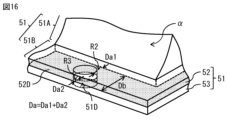
- a through hole 51D may be provided instead of the cutout portion 51C.
- the through hole 51D is formed to penetrate the flange portion 51B, the welded portion 52D, and the laminated body 52, 53.
- the through hole 51D has a circular or elliptical shape.
- two narrow regions R2, R3 are provided adjacent to the through hole 51D. If the width of the narrow region R2 is Da1 and the width of the narrow region R3 is Da2, Da1 + Da2 corresponds to the width Da in the above embodiment and its modified examples.
- the through hole 51D may be rectangular when viewed from the normal direction of the flange portion 51B, as shown in FIG. 17, for example.
- the longitudinal direction of the through hole 51D is parallel to the extension direction of the end edge of the flange portion 51B, for example.
- the longitudinal direction of the through hole 51D may be perpendicular to the extension direction of the end edge of the flange portion 51B. Even in this case, the same effect as when the cutout portion 51C is provided can be obtained.
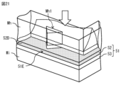
- a non-welded region 51E may be provided instead of the notch portion 51C.
- the non-welded region 51E is a region where the laminate 52 (resin layer 52a) and the laminate 53 (resin layer 53a) are only in contact with each other, and where the laminate 52 (resin layer 52a) and the laminate 53 (resin layer 53a) can be peeled off without heating.
- the non-welded region 51E is exposed, for example, at the end of the flange portion 51B.
- the non-welded region 51E may have a gap, or the laminate 52 (resin layer 52a) and the laminate 53 (resin layer 53a) may be in close contact with each other and no gap may exist.
- the non-welded region 51E may have an acute corner protruding toward the storage space ⁇ of the storage portion 51A when viewed from a direction where the entire flange portion 51B can be seen. In this case, a narrow region R4 may be formed adjacent to the acute corner. Even in this case, the same effect as in the case where the notch portion 51C is provided can be obtained.
- the laminates 52 and 53 are placed on a mold piece Mg having a flat surface.
- the end of the laminate 52 is pressed with a mold piece Mf having a cutout portion Mf1 corresponding to the shape of the non-welded region 51E.
- This forms a welded portion 52D having a narrow region R4.
- the area where the welded portion 52D is not formed becomes the non-welded region 51E.
- a non-welded region 51F may be provided instead of the notch portion 51C.
- the non-welded region 51F is a region where the laminate 52 (resin layer 52a) and the laminate 53 (resin layer 53a) are simply in contact with each other, and where the laminate 52 (resin layer 52a) and the laminate 53 (resin layer 53a) can be peeled off without heating.
- the non-welded region 51F is provided, for example, in a portion of the flange portion 51B that communicates with the accommodation space ⁇ of the accommodation portion 51A.
- the non-welded region 51F may have a gap, or the laminate 52 (resin layer 52a) and the laminate 53 (resin layer 53a) may be in close contact with each other and no gap may exist.
- the gap may be filled with a heat absorbing agent 54.
- the non-welded region 51F may have an acute corner protruding toward the end face of the flange portion 51B when viewed from a direction in which the entire flange portion 51B can be seen.
- the narrow region R5 may be formed adjacent to the acute corner. Even in this case, the same effect as when the cutout portion 51C is provided can be obtained.
- the laminates 52 and 53 are placed on a mold piece Mi having a flat surface.
- the end of the laminate 52 is pressed with a mold piece Mh having a cutout portion Mh1 corresponding to the shape of the non-welded region 51F.
- This forms a welded portion 52D having a narrow region R5.
- the area where the welded portion 52D is not formed becomes the non-welded region 51F.
- the type of the electrode reactant is not particularly limited.
- the electrode reactant may be other Group 1 elements in the long-form periodic table, such as sodium and potassium, or Group 2 elements in the long-form periodic table, such as magnesium and calcium, or other light metals, such as aluminum.
- the present technology can also be configured as follows. ⁇ 1> Batteries and a heat absorbing member having a heat absorbing agent and a container for accommodating the heat absorbing agent; the heat absorbing member is disposed adjacent to the battery, The battery pack, wherein the container has a notch. ⁇ 2> The container comprises: A storage section that stores the heat absorbing agent; and a flange portion provided around the housing portion, The battery pack according to ⁇ 1>, wherein the notch is provided in the flange portion.
- the container has a first container part and a second container part;
- the first container part has a first housing portion constituting a part of the housing portion and a first flange portion constituting a part of the flange portion
- the second container part has a second housing portion constituting a part of the housing portion and a second flange portion constituting a part of the flange portion, an accommodation space of the accommodation portion is formed by the first accommodation portion and the second accommodation portion, the first flange portion and the second flange portion are bonded to each other;
- the first container part is constructed from a first sheet material; the first housing portion and the first flange portion are integrally formed by the first sheet material, the second container part is constructed from a second sheet material; the second housing portion and the second flange portion are integrally formed by the second sheet material, a portion of the first sheet material corresponding to the first flange portion and a portion of the second sheet material corresponding to the second flange portion are bonded to each other;
- the battery pack according to any one of ⁇ 3> to ⁇ 5>, wherein the cutout is formed so as to penetrate the first sheet material and the second sheet material.
- the first flange portion and the second flange portion are each a laminate including a resin layer, a resin layer of the first flange portion and a resin layer of the second flange portion are welded to each other,
- the cutout is formed so as to penetrate a welded portion between a resin layer of the first flange portion and a resin layer of the second flange portion.
- a plurality of the batteries are provided, The battery pack according to any one of ⁇ 1> to ⁇ 8>, wherein the cutouts are disposed at positions adjacent to two of the batteries adjacent to each other.
- Each of the batteries and the heat absorbing member has a columnar shape, The battery pack according to ⁇ 9>, wherein the cutout is disposed in a central region of the heat absorbing member in a longitudinal direction of the heat absorbing member.
- the container comprises: A storage section that stores the heat absorbing agent; a flange portion provided around the housing portion and having a peelable portion that can be peeled off by heating to communicate the housing space of the housing portion with the outside; the peelable portion has a narrow region where the width of the peelable portion is locally narrower than the width of the flange portion.
- flange portion has a notch, a through hole, a separable portion that can be separated without heating, or a separable portion that communicates with the storage space, at a location adjacent to the narrow area.
- the container has a first container part and a second container part;
- the first container part has a first housing portion constituting a part of the housing portion and a first flange portion constituting a part of the flange portion
- the second container part has a second housing portion constituting a part of the housing portion and a second flange portion constituting a part of the flange portion, an accommodation space of the accommodation portion is formed by the first accommodation portion and the second accommodation portion, the first flange portion and the second flange portion are bonded to each other;
- the battery pack according to ⁇ 11> or ⁇ 12>, wherein an adhesive portion of the first flange portion and an adhesive portion of the second flange portion correspond to the peelable portion.
- the first container part is constructed from a first sheet material; the first housing portion and the first flange portion are integrally formed by the first sheet material, the second container part is constructed from a second sheet material; the second housing portion and the second flange portion are integrally formed by the second sheet material, a portion of the first sheet material corresponding to the first flange portion and a portion of the second sheet material corresponding to the second flange portion are bonded to each other;
- the first flange portion and the second flange portion are each a laminate including a resin layer, a resin layer of the first flange portion and a resin layer of the second flange portion are welded to each other,
- a plurality of the batteries are provided, The battery pack according to any one of ⁇ 11> to ⁇ 17>, wherein the cutout, the through hole, the separable portion, or the separation portion is disposed at a position adjacent to two of the batteries adjacent to each other.
- Each of the batteries and the heat absorbing member has a columnar shape, The battery pack according to ⁇ 18>, wherein the cutout, the through hole, the separable portion, or the separable portion is disposed in a central region of the heat absorbing member in a longitudinal direction of the heat absorbing member.
Landscapes
- Chemical & Material Sciences (AREA)
- Chemical Kinetics & Catalysis (AREA)
- Electrochemistry (AREA)
- General Chemical & Material Sciences (AREA)
- Engineering & Computer Science (AREA)
- Manufacturing & Machinery (AREA)
- Battery Mounting, Suspending (AREA)
- Secondary Cells (AREA)
Priority Applications (1)
| Application Number | Priority Date | Filing Date | Title |
|---|---|---|---|
| JP2025540615A JPWO2025037475A1 (https=) | 2023-08-14 | 2024-06-17 |
Applications Claiming Priority (2)
| Application Number | Priority Date | Filing Date | Title |
|---|---|---|---|
| JP2023-132005 | 2023-08-14 | ||
| JP2023132005 | 2023-08-14 |
Publications (1)
| Publication Number | Publication Date |
|---|---|
| WO2025037475A1 true WO2025037475A1 (ja) | 2025-02-20 |
Family
ID=94632791
Family Applications (1)
| Application Number | Title | Priority Date | Filing Date |
|---|---|---|---|
| PCT/JP2024/021811 Pending WO2025037475A1 (ja) | 2023-08-14 | 2024-06-17 | 電池パック |
Country Status (2)
| Country | Link |
|---|---|
| JP (1) | JPWO2025037475A1 (https=) |
| WO (1) | WO2025037475A1 (https=) |
Citations (5)
| Publication number | Priority date | Publication date | Assignee | Title |
|---|---|---|---|---|
| WO2010098067A1 (ja) * | 2009-02-24 | 2010-09-02 | パナソニック株式会社 | 電池モジュールとそれを用いた電池モジュール集合体 |
| JP2012221717A (ja) * | 2011-04-08 | 2012-11-12 | Panasonic Corp | 電池モジュール |
| US20200287252A1 (en) * | 2016-11-29 | 2020-09-10 | Beijing Key Power Technologies Co., Ltd. | Heat Absorption and Heat Insulation Structure for Battery Module |
| JP2023069718A (ja) * | 2021-11-08 | 2023-05-18 | 大日本印刷株式会社 | 仕切り部材用外装材、仕切り部材、および構造体 |
| WO2023132234A1 (ja) * | 2022-01-06 | 2023-07-13 | 株式会社村田製作所 | 電池パック |
-
2024
- 2024-06-17 WO PCT/JP2024/021811 patent/WO2025037475A1/ja active Pending
- 2024-06-17 JP JP2025540615A patent/JPWO2025037475A1/ja active Pending
Patent Citations (5)
| Publication number | Priority date | Publication date | Assignee | Title |
|---|---|---|---|---|
| WO2010098067A1 (ja) * | 2009-02-24 | 2010-09-02 | パナソニック株式会社 | 電池モジュールとそれを用いた電池モジュール集合体 |
| JP2012221717A (ja) * | 2011-04-08 | 2012-11-12 | Panasonic Corp | 電池モジュール |
| US20200287252A1 (en) * | 2016-11-29 | 2020-09-10 | Beijing Key Power Technologies Co., Ltd. | Heat Absorption and Heat Insulation Structure for Battery Module |
| JP2023069718A (ja) * | 2021-11-08 | 2023-05-18 | 大日本印刷株式会社 | 仕切り部材用外装材、仕切り部材、および構造体 |
| WO2023132234A1 (ja) * | 2022-01-06 | 2023-07-13 | 株式会社村田製作所 | 電池パック |
Also Published As
| Publication number | Publication date |
|---|---|
| JPWO2025037475A1 (https=) | 2025-02-20 |
Similar Documents
| Publication | Publication Date | Title |
|---|---|---|
| KR102008594B1 (ko) | 고출력 애플리케이션을 위한 장수명 각형 배터리 셀 | |
| JP7669513B2 (ja) | 電池モジュールおよびこれを含む電池パック | |
| JP7062863B2 (ja) | ベンティング部材を含むパウチ型電池セル及びこれを含む電池パック | |
| WO2023132234A1 (ja) | 電池パック | |
| JP2022510320A (ja) | 電池モジュールおよびこれを含む電池パック | |
| JP2013101899A (ja) | 電池セル及びそれを含む電池モジュール | |
| KR20120139970A (ko) | 안전장치가 구비된 배터리 | |
| JP7551214B2 (ja) | 電池モジュールおよびこれを含む電池パック | |
| JP5004769B2 (ja) | 二次電池モジュール | |
| JP2021501959A (ja) | バッテリーモジュール及びこれを含むバッテリーパック | |
| JP2023537017A (ja) | 電池モジュールおよびそれを含む電池パック | |
| JP2023537015A (ja) | 電池モジュールおよびこれを含む電池パック | |
| JP2023507304A (ja) | 電解液補充の可能なパウチ型電池セル | |
| JP7536356B2 (ja) | 電池モジュールおよびそれを含む電池パック | |
| JP7536357B2 (ja) | 電池モジュールおよびこれを含む電池パック | |
| WO2025037475A1 (ja) | 電池パック | |
| WO2025037464A1 (ja) | 電池パック | |
| EP4503272A1 (en) | Battery module and battery pack comprising cooling part | |
| US20260128448A1 (en) | Battery pack | |
| US20240274919A1 (en) | Battery pack | |
| JP2024112761A (ja) | 電池パック | |
| US20240266628A1 (en) | Battery pack | |
| KR20230133621A (ko) | 배터리 팩 및 이를 포함하는 전력 저장 장치 | |
| WO2025187152A1 (ja) | 電池パック | |
| KR102780575B1 (ko) | 자동차 배터리 및 2차전지 배터리 화재시 소화 및 확산을 지연할 수 있는 필름 포장지 |
Legal Events
| Date | Code | Title | Description |
|---|---|---|---|
| 121 | Ep: the epo has been informed by wipo that ep was designated in this application |
Ref document number: 24854066 Country of ref document: EP Kind code of ref document: A1 |
|
| ENP | Entry into the national phase |
Ref document number: 2025540615 Country of ref document: JP Kind code of ref document: A |
|
| WWE | Wipo information: entry into national phase |
Ref document number: 2025540615 Country of ref document: JP |
|
| NENP | Non-entry into the national phase |
Ref country code: DE |