WO2025033100A1 - 緩衝器 - Google Patents
緩衝器 Download PDFInfo
- Publication number
- WO2025033100A1 WO2025033100A1 PCT/JP2024/025313 JP2024025313W WO2025033100A1 WO 2025033100 A1 WO2025033100 A1 WO 2025033100A1 JP 2024025313 W JP2024025313 W JP 2024025313W WO 2025033100 A1 WO2025033100 A1 WO 2025033100A1
- Authority
- WO
- WIPO (PCT)
- Prior art keywords
- valve
- chamber
- passage
- shock absorber
- piston
- Prior art date
- Legal status (The legal status is an assumption and is not a legal conclusion. Google has not performed a legal analysis and makes no representation as to the accuracy of the status listed.)
- Pending
Links
Images









Classifications
-
- F—MECHANICAL ENGINEERING; LIGHTING; HEATING; WEAPONS; BLASTING
- F16—ENGINEERING ELEMENTS AND UNITS; GENERAL MEASURES FOR PRODUCING AND MAINTAINING EFFECTIVE FUNCTIONING OF MACHINES OR INSTALLATIONS; THERMAL INSULATION IN GENERAL
- F16F—SPRINGS; SHOCK-ABSORBERS; MEANS FOR DAMPING VIBRATION
- F16F9/00—Springs, vibration-dampers, shock-absorbers, or similarly-constructed movement-dampers using a fluid or the equivalent as damping medium
- F16F9/32—Details
-
- F—MECHANICAL ENGINEERING; LIGHTING; HEATING; WEAPONS; BLASTING
- F16—ENGINEERING ELEMENTS AND UNITS; GENERAL MEASURES FOR PRODUCING AND MAINTAINING EFFECTIVE FUNCTIONING OF MACHINES OR INSTALLATIONS; THERMAL INSULATION IN GENERAL
- F16F—SPRINGS; SHOCK-ABSORBERS; MEANS FOR DAMPING VIBRATION
- F16F9/00—Springs, vibration-dampers, shock-absorbers, or similarly-constructed movement-dampers using a fluid or the equivalent as damping medium
- F16F9/32—Details
- F16F9/34—Special valve constructions; Shape or construction of throttling passages
- F16F9/348—Throttling passages in the form of annular discs or other plate-like elements which may or may not have a spring action, operating in opposite directions or singly, e.g. annular discs positioned on top of the valve or piston body
-
- F—MECHANICAL ENGINEERING; LIGHTING; HEATING; WEAPONS; BLASTING
- F16—ENGINEERING ELEMENTS AND UNITS; GENERAL MEASURES FOR PRODUCING AND MAINTAINING EFFECTIVE FUNCTIONING OF MACHINES OR INSTALLATIONS; THERMAL INSULATION IN GENERAL
- F16F—SPRINGS; SHOCK-ABSORBERS; MEANS FOR DAMPING VIBRATION
- F16F9/00—Springs, vibration-dampers, shock-absorbers, or similarly-constructed movement-dampers using a fluid or the equivalent as damping medium
- F16F9/32—Details
- F16F9/50—Special means providing automatic damping adjustment, i.e. self-adjustment of damping by particular sliding movements of a valve element, other than flexions or displacement of valve discs; Special means providing self-adjustment of spring characteristics
-
- F—MECHANICAL ENGINEERING; LIGHTING; HEATING; WEAPONS; BLASTING
- F16—ENGINEERING ELEMENTS AND UNITS; GENERAL MEASURES FOR PRODUCING AND MAINTAINING EFFECTIVE FUNCTIONING OF MACHINES OR INSTALLATIONS; THERMAL INSULATION IN GENERAL
- F16F—SPRINGS; SHOCK-ABSORBERS; MEANS FOR DAMPING VIBRATION
- F16F9/00—Springs, vibration-dampers, shock-absorbers, or similarly-constructed movement-dampers using a fluid or the equivalent as damping medium
- F16F9/32—Details
- F16F9/50—Special means providing automatic damping adjustment, i.e. self-adjustment of damping by particular sliding movements of a valve element, other than flexions or displacement of valve discs; Special means providing self-adjustment of spring characteristics
- F16F9/512—Means responsive to load action, i.e. static load on the damper or dynamic fluid pressure changes in the damper, e.g. due to changes in velocity
Definitions
- the present invention relates to a shock absorber.
- This application claims priority based on Japanese Patent Application No. 2023-129402, filed on August 8, 2023, the contents of which are incorporated herein by reference.
- Some shock absorbers have variable damping force that is sensitive to frequency (see, for example, Patent Document 1).
- shock absorbers There is a demand for reducing the cost of shock absorbers.
- the present invention therefore aims to provide a shock absorber that can reduce costs.
- the shock absorber includes a cylindrical cylinder filled with fluid, a dividing member dividing the interior of the cylinder into a first chamber and a second chamber, an axial member inserted into the dividing member, a first flow path through which the fluid flows out of one of the first and second chambers, a second flow path at least partially parallel to the first flow path, a first valve member provided in the first flow path and capable of passing the fluid in the one chamber into the other chamber, a partition member having a wall and a bottom, penetrating the axial member and connected to the second flow path to form a back pressure chamber that generates a force in the valve closing direction in the first valve member, a volume variable member disposed opposite the bottom and deformed by the pressure of the fluid to vary the volume of the back pressure chamber, a seal member that seals between the other chamber and the wall, and a support member that directly or indirectly applies a biasing force in the direction of separation to the first valve member and the volume variable member.
- the above-mentioned aspect makes it possible to provide a shock absorber that can reduce costs.
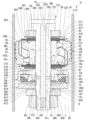
- FIG. 1 is a cross-sectional view showing a shock absorber according to a first embodiment of the present invention, taken along a cross section including a central axis line CL.
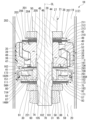
- FIG. 2 is a diagram showing a configuration provided on a piston rod of the shock absorber of the first embodiment, and is a partially enlarged cross-sectional view showing a portion A in FIG. 1 .
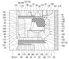
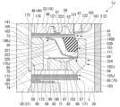
- FIG. 3 is a diagram showing a main part of the shock absorber of the first embodiment, and is a partially enlarged cross-sectional view showing part B of FIG. 2 .
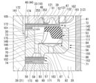
- FIG. 3 is a view showing a main part of a modified example of the shock absorber of the first embodiment, and is a partially enlarged cross-sectional view showing a portion corresponding to part B in FIG. 2 .
- FIG. 3 is a view showing a main part of a modified example of the shock absorber of the first embodiment, and is a partially enlarged cross-sectional view showing a portion corresponding to part B in FIG. 2 .
- FIG. 3 is a view showing a main part of a modified example of the shock absorber of the first embodiment, and is a partially enlarged cross-sectional view showing a portion corresponding to part B in FIG. 2 .
- FIG. 3 is a view showing a main part of a modified example of the shock absorber of the first embodiment, and is a partially enlarged cross-sectional view showing a portion corresponding to part B in FIG. 2 .
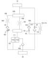
- FIG. 2 is a hydraulic circuit diagram of a configuration provided in a piston rod of the shock absorber of the first embodiment.
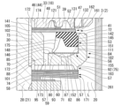
- FIG. 3 is a diagram showing a main part of a shock absorber according to a second embodiment of the present invention, and is a partially enlarged cross-sectional view showing a portion corresponding to part B in FIG. 2 .
- FIG. 10 is a diagram showing a main part of a shock absorber according to a third embodiment of the present invention, and is a partially enlarged cross-sectional view showing a portion corresponding to part B in FIG. 2 .
- FIG. 10 is a diagram showing a main part of a shock absorber according to a fourth embodiment of the present invention, and is a partially enlarged cross-sectional view showing a portion corresponding to part B in FIG. 2 .
- FIG. 10 is a diagram showing a main part of a shock absorber according to a fourth embodiment of the present invention, and is a partially enlarged cross-sectional view showing a portion corresponding to part B in FIG. 2 .
- FIG. 13 is a diagram showing a configuration provided on a piston rod of a shock absorber according to a fifth embodiment of the present invention, and is a partially enlarged cross-sectional view showing a portion corresponding to part A in FIG.
- FIG. 13 is a diagram showing a main part of the shock absorber of the fifth embodiment, and is a partially enlarged cross-sectional view showing part C of FIG. 12 .
- FIG. 13 is a diagram showing a main part of a shock absorber according to a sixth embodiment of the present invention, and is a partially enlarged cross-sectional view showing a portion corresponding to part B in FIG. 2 .
- FIG. 13 is a diagram showing a main part of a shock absorber according to a seventh embodiment of the present invention, and is a partially enlarged cross-sectional view showing a portion corresponding to part B in FIG. 2 .
- FIG. 13 is a diagram showing a configuration provided on a piston rod of a shock absorber according to an eighth embodiment of the present invention, and is a partially enlarged cross-sectional view showing a portion corresponding to FIG. 2 .
- FIG. 17 is a diagram showing a main part of the shock absorber of the eighth embodiment, and is a partially enlarged cross-sectional view showing part D in FIG. 16 .
- FIG. 23 is a hydraulic circuit diagram of a configuration provided in a piston rod of the shock absorber of the eighth embodiment.
- FIG. 1 A first embodiment of a shock absorber according to the present invention will be described with reference to Figures 1 to 8.
- the upper side in the drawings will be referred to as “top” and the lower side in the drawings will be referred to as “bottom”.
- the central axis of the shock absorber may be indicated by the symbol CL. The same applies to the other embodiments.
- the shock absorber 1 of the first embodiment is a so-called twin-cylinder hydraulic shock absorber, as shown in FIG. 1, and includes a cylindrical cylinder 2 filled with oil L, which is a fluid.
- the cylinder 2 includes a cylindrical inner cylinder 3, a cylindrical outer cylinder 4 with a bottom that is larger in diameter than the inner cylinder 3 and is arranged concentrically with the inner cylinder 3 so as to cover the inner cylinder 3, and a cover 5 that is arranged to cover the upper opening side of the outer cylinder 4.
- a reservoir chamber 6 is formed between the inner cylinder 3 and the outer cylinder 4.
- the shock absorber 1 of the first embodiment is a twin-cylinder type, but the scope of the present invention is not limited to this and is applicable to single-cylinder and triple-cylinder types, etc.
- the outer tube 4 is made up of a cylindrical body member 11 and a bottom member 12 that closes the lower part of the body member 11.
- the bottom member 12 is welded to the body member 11 around its entire circumference while being fitted into the lower side of the body member 11. In this way, the bottom member 12 is fixed to the lower side of the body member 11.
- An attachment eye 13 is fixed to the outside of the bottom member 12, opposite the body member 11.
- the cover 5 has a cylindrical portion 15 and an inner flange portion 16 that extends radially inward from the upper end side of the cylindrical portion 15.
- the cover 5 is placed over the body member 11 so that the upper end opening of the body member 11 is covered with the inner flange portion 16 and the outer circumferential surface of the body member 11 is covered with the cylindrical portion 15. In this state, a portion of the cylindrical portion 15 is crimped radially inward and fixed to the body member 11.
- the shock absorber 1 is equipped with a piston 18 (dividing member).
- the piston 18 is slidably fitted within the inner tube 3 of the cylinder 2.
- This piston 18 divides the inside of the inner tube 3 of the cylinder 2 into a first chamber 19 (one chamber) and a second chamber 20 (the other chamber).
- Oil liquid L is sealed within the first chamber 19 and second chamber 20 of the inner tube 3, and oil liquid L and gas G are sealed within the reservoir chamber 6 between the inner tube 3 and the outer tube 4.
- the fluid used There is no particular limitation regarding the fluid used.
- the shock absorber 1 is equipped with a piston rod 21 (shaft-shaped member).
- One end of the piston rod 21 is disposed within the inner tube 3 of the cylinder 2 and inserted into the piston 18, while the other end extends outside the cylinder 2.
- the piston 18 and the piston rod 21 move together.
- the piston rod 21 increases the amount of protrusion from the cylinder 2
- the piston 18 moves toward the first chamber 19.
- the piston rod 21 decreases the amount of protrusion from the cylinder 2
- the piston 18 moves toward the second chamber 20.
- a rod guide 22 is fitted to the upper opening side of the inner cylinder 3 and the outer cylinder 4, and a seal member 23 is attached to the outer cylinder 4 above the rod guide 22, which is closer to the outside of the cylinder 2.
- a friction member 24 is provided between the rod guide 22 and the seal member 23.
- the rod guide 22, the seal member 23 and the friction member 24 are all annular, and the piston rod 21 is slidably inserted inside the rod guide 22, the friction member 24 and the seal member 23, and extends from the inside of the cylinder 2 to the outside.
- the rod guide 22 supports the piston rod 21 so that it can move axially while restricting its radial movement, guiding the movement of the piston rod 21.
- the seal member 23 is in close contact with the outer tube 4 at its outer periphery and in sliding contact with the outer periphery of the piston rod 21 moving in the axial direction at its inner periphery, preventing the oil liquid L in the inner tube 3 and the gas G and oil liquid L in the reservoir chamber 6 in the outer tube 4 from leaking to the outside.
- the friction member 24 is in sliding contact with the outer periphery of the piston rod 21 at its inner periphery, generating frictional resistance in the piston rod 21.
- the outer periphery of the rod guide 22 is stepped, with the upper part being larger in diameter than the lower part, and the smaller diameter lower part fits into the inner periphery of the upper end of the inner cylinder 3, while the larger diameter upper part fits into the inner periphery of the upper part of the outer cylinder 4.
- a base valve 25 that separates the second chamber 20 and the reservoir chamber 6 is installed on the bottom member 12 of the outer cylinder 4, and the inner periphery of the lower end of the inner cylinder 3 fits into this base valve 25.
- a portion (not shown) of the upper end of the outer cylinder 4 is crimped radially inward, and this crimped portion and the rod guide 22 hold the seal member 23 in place.
- the piston rod 21 has a main shaft portion 27 and a mounting shaft portion 28 having an outer diameter smaller than that of the main shaft portion 27.
- the mounting shaft portion 28 is disposed in the cylinder 2, and the piston 18 and the like are attached to the mounting shaft portion 28.
- the end face of the main shaft portion 27 on the mounting shaft portion 28 side in the axial direction of the piston rod 21 expands in the direction perpendicular to the axis.
- a passage groove 30 extending in the axial direction is formed in the outer periphery of the mounting shaft portion 28 at a middle position in the axial direction, and a male thread 31 is formed at a tip position on the opposite side of the main shaft portion 27 in the axial direction.
- a plurality of passage grooves 30 are formed at intervals in the circumferential direction of the mounting shaft portion 28, and are formed so that the cross-sectional shape on a plane perpendicular to the central axis of the piston rod 21 is rectangular, square, or D-shaped.
- the passage groove 30 may be achieved by making the inside of the piston rod 21 hollow.
- the protruding part of the piston rod 21 from the cylinder 2 is arranged at the top and supported by the vehicle body, and the mounting eye 13 on the cylinder 2 side is arranged at the bottom and connected to the wheel side.
- the cylinder 2 side may be supported by the vehicle body and the piston rod 21 may be connected to the wheel side.
- the fluid resistance of the flow path formed in at least one of the piston 18 and the piston rod 21 is made to differ depending on the speed and amplitude of the vibration, and the ride comfort is improved by suppressing the vibration.
- inertial force and centrifugal force generated in the vehicle body as the vehicle travels also act between the cylinder 2 and the piston rod 21.
- centrifugal force is generated in the vehicle body when the driving direction is changed by steering, and a force based on this centrifugal force acts between the cylinder 2 and the piston rod 21.
- shock absorber 1 has good characteristics against vibrations caused by forces generated in the vehicle body as the vehicle travels, providing high stability during vehicle travel.
- the piston 18 is composed of a metal piston body 33 supported by the piston rod 21 and an annular sliding member 34 that is integrally attached to the outer circumferential surface of the piston body 33 and slides inside the inner cylinder 3.
- the piston body 33 is formed with a plurality of passage holes 35 (only one is shown in FIG. 2 because it is a cross-section) and an annular passage groove 36 that connects the ends of these passage holes 35 opposite the first chamber 19.
- the piston body 33 is also formed with a plurality of passage holes 37 (only one is shown in FIG. 2 because it is a cross-section) and an annular passage groove 38 that connects the ends of these passage holes 37 on the first chamber 19 side.
- the multiple passage holes 35 are formed in the circumferential direction of the piston body 33 with one passage hole 37 between them.
- the passages in the multiple passage holes 35 and the passage in the passage groove 36 form a piston passage 39 that penetrates the piston 18 in the axial direction of the piston 18 and can communicate between the first chamber 19 and the second chamber 20.
- the passages in the multiple passage holes 37 and the passage in the passage groove 38 form a piston passage 40 that penetrates the piston 18 in the axial direction of the piston 18 and can communicate between the first chamber 19 and the second chamber 20.
- the piston passage 39 is provided with a damping force generating mechanism 41 that opens and closes the piston passage 39 to generate a damping force.
- the damping force generating mechanism 41 is arranged on the second chamber 20 side, which is one end side of the piston 18 in the axial direction, and is attached to the piston rod 21. By arranging the damping force generating mechanism 41 on the second chamber 20 side, the piston passage 39 allows the oil liquid L flowing out from the first chamber 19 toward the second chamber 20 when the piston 18 moves toward the first chamber 19 side, that is, during the extension stroke.
- the damping force generating mechanism 41 provided for the piston passage 39 is an extension-side damping force generating mechanism that generates a damping force by suppressing the flow of oil liquid L from the extension-side piston passage 39 to the second chamber 20.
- the piston passage 40 is provided with a damping force generating mechanism 42 that opens and closes the piston passage 40 to generate a damping force.
- the damping force generating mechanism 42 is arranged on the first chamber 19 side, which is the other axial end side of the piston 18, and is attached to the piston rod 21. By arranging the damping force generating mechanism 42 on the first chamber 19 side, the piston passage 40 allows the oil liquid L flowing out from the second chamber 20 toward the first chamber 19 when the piston 18 moves toward the second chamber 20 side, that is, during the compression stroke.
- the damping force generating mechanism 42 provided for the piston passage 40 is a compression side damping force generating mechanism that generates a damping force by suppressing the flow of oil liquid L from the compression side piston passage 40 to the first chamber 19.
- piston passage 39 and piston passage 40 are connected so that oil liquid L flows between the first chamber 19 and the second chamber 20 as the piston 18 moves. Oil liquid L passes through piston passage 39 when the piston rod 21 and piston 18 move toward the extension side, and oil liquid L passes through piston passage 40 when the piston rod 21 and piston 18 move toward the contraction side.
- the piston body 33 is generally disk-shaped, and a through hole 44 is formed in its radial center, penetrating in the axial direction, for inserting the mounting shaft portion 28 of the piston rod 21.
- the through hole 44 has a small diameter hole portion 45 on one axial side into which the mounting shaft portion 28 of the piston rod 21 fits, and a large diameter hole portion 46 on the other axial side, which has an inner diameter larger than that of the small diameter hole portion 45.
- a ring-shaped valve seat portion 47 constituting part of the damping force generating mechanism 41 is formed at the axial end of the piston body 33 on the second chamber 20 side, radially outward from the opening of the passage groove 36 on the second chamber 20 side.
- an inner seat portion 48 is formed at the axial end of the piston body 33 on the second chamber 20 side, radially inward from the opening of the passage groove 36 on the second chamber 20 side.
- the large diameter hole portion 46 of the insertion hole 44 is provided closer to the valve seat portion 47 and inner seat portion 48 in the axial direction of the piston body 33 than the small diameter hole portion 45.
- annular valve seat portion 49 that constitutes part of the damping force generating mechanism 42 is formed at the axial end of the piston body 33 on the first chamber 19 side, radially outward from the opening of the passage groove 38 on the first chamber 19 side.
- an inner seat portion 50 is formed at the axial end of the piston body 33 on the first chamber 19 side, radially inward from the opening of the passage groove 38 on the first chamber 19 side.
- the radial side of the valve seat portion 47 opposite the insertion hole 44 forms a step that is lower in axial height than the valve seat portion 47, and the opening of the second chamber 20 side of the compression side piston passage 40 is located in this step-like portion.
- the radial side of the valve seat portion 49 opposite the insertion hole 44 forms a step that is lower in axial height than the valve seat portion 49, and the opening of the first chamber 19 side of the piston passage 39 in the extension side passage hole 35 is located in this step-like portion.
- the valve seat portion 47 and inner seat portion 48 side of the piston in order from the piston 18 side in the axial direction, there are provided one disk 51, one valve disk 52, one pilot valve 53, one pilot case 56 (partition member), multiple disks 57, one disk 58, one disk 59, and annular member 60, with the mounting shaft portion 28 of the piston rod 21 fitted inside each.
- the disks 51, 57-59, the valve disk 52, and the annular member 60 are all perforated circular flat plates of a constant thickness into which the mounting shaft portion 28 of the piston rod 21 can be fitted inside.
- the pilot valve 53 and the pilot case 56 are all annular in shape into which the mounting shaft portion 28 of the piston rod 21 can be fitted inside.
- the pilot case 56 is a bottomed cylinder with a rod insertion hole 70 formed in the center in the radial direction that penetrates the pilot case 56 in the axial direction of the pilot case 56.
- the pilot case 56 has a perforated disk-shaped bottom 71, a cylindrical wall portion 72 that protrudes from the outer peripheral edge of the bottom 71 to one side along the axial direction of the bottom 71, and a cylindrical inner cylindrical portion 73 that protrudes from the inner peripheral edge of the bottom 71 to the same side as the wall portion 72 along the axial direction of the bottom 71.
- the pilot case 56 also has an inner seat portion 74 that protrudes from the inner peripheral edge of the bottom 71 to the opposite side to the inner cylindrical portion 73 along the axial direction of the bottom 71, and a valve seat portion 75 (valve seat) that protrudes from outside the inner seat portion 74 in the radial direction of the bottom 71 to the same side as the inner seat portion 74 along the axial direction of the bottom 71.
- a valve seat portion 75 valve seat
- the pilot case 56 has the mounting shaft 28 of the piston rod 21 fitted into the rod insertion hole 70. At that time, the pilot case 56 is oriented in such a way that the wall portion 72 and the inner cylindrical portion 73 extend from the bottom portion 71 toward the piston 18 in the axial direction of the piston rod 21.
- the bottom 71 has a seat portion 80 and a recess 82 formed on the side of the wall portion 72 and the inner cylindrical portion 73 in the axial direction of the bottom 71.
- the seat portion 80 and the recess 82 are formed at a position between the wall portion 72 and the inner cylindrical portion 73 in the radial direction of the bottom 71.
- the seat portion 80 is annular and has a seat surface 84 and a seat surface 85 that is disposed radially inward of the seat surface 84 of the bottom portion 71. Both seat surfaces 84 and 85 are flat annular shapes that extend perpendicularly to the central axis of the bottom portion 71 and are disposed on the same plane.
- the recess 82 is formed between the seat surfaces 84, 85.
- the recess 82 has a stopper surface 86 that is recessed from the seat surfaces 84, 85 in the axial direction of the bottom 71.
- the recess 82 is shaped such that the width in the radial direction of the bottom 71 becomes narrower as the depth increases.
- the recess 82 is formed in a circular ring shape in FIG. 3, but it does not have to be a circular ring shape. In other words, it is sufficient that the recess 82 is formed on at least a portion of the seat portion 80.
- the bottom 71 is formed with an outer through hole 87 (first through hole) that penetrates along the axial direction of the bottom 71.
- the bottom 71 is formed with a plurality of outer through holes 87 spaced apart in the circumferential direction of the bottom 71 (only one is shown in FIG. 2 because it is a cross-section). It is sufficient that at least one outer through hole 87 is provided in the bottom 71.
- the bottom 71 has an inner through hole 88 (second through hole) that penetrates the bottom 71 along the axial direction of the bottom 71, inside the seat portion 80 in the radial direction of the bottom 71 and outside the inner cylindrical portion 73 and the inner seat portion 74 in the radial direction of the bottom 71.
- the bottom 71 has a plurality of inner through holes 88 (only one is shown in FIG. 3 because it is a cross-section) that are spaced apart from each other in the circumferential direction of the bottom 71. It is sufficient that at least one inner through hole 88 is provided in the bottom 71.
- the outer through hole 87 is provided outside the inner through hole 88 in the radial direction of the pilot case 56, i.e., in the radial direction of the bottom 71.
- the inner seat portion 74 is annular.
- the valve seat portion 75 is annular and radially outward of the inner seat portion 74.
- the valve seat portion 75 protrudes from the bottom portion 71 on the same side as the inner seat portion 74 along the axial direction of the bottom portion 71.
- the valve seat portion 75 has a sector shape and is provided in a plurality of sectors along the circumferential direction of the bottom portion 71, but is not limited thereto and may be, for example, an annular shape.
- the valve seat portion 75 has a plurality of valve seat constituent portions 91 (only one is shown in FIG. 2 due to the cross-sectional view) and a plurality of valve seat constituent portions 92 (only one is shown in FIG. 2 due to the cross-sectional view).
- the multiple valve seat components 91 are identically shaped in an arc.
- the multiple valve seat components 91 are located outside the inner seat portion 74 in the radial direction of the pilot case 56, and are arranged intermittently at equal intervals on the same circle coaxial with the inner seat portion 74.
- the valve seat components 92 are of the same shape and convex outward in the radial direction of the pilot case 56. Each of the valve seat components 92 connects adjacent valve seat components 91 in the circumferential direction of the pilot case 56 and convex outward in the radial direction of the pilot case 56.
- the valve seat components 92 have an outer surface that faces outward in the circumferential and radial directions of the pilot case 56 and convex outward in the radial direction of the pilot case 56.
- the valve seat components 92 have an inner surface that faces inward in the circumferential and radial directions of the pilot case 56 and convex outward in the radial direction of the pilot case 56.
- the valve seat components 92 protrude radially outward from the broken portions of the valve seat components 91 that are arranged intermittently.
- the passage recess 93 is surrounded by the inner seat portion 74 and the valve seat portion 75.
- the passage recess 93 is continuous around the entire circumference of the pilot case 56.
- the passage recess 93 is recessed in the axial direction of the pilot case 56 from the tip surface on the protruding side of the inner seat portion 74 and the tip surface on the protruding side of the valve seat portion 75.
- the bottom surface of the passage recess 93 is formed by the bottom portion 71.
- the inner seat portion 74 is formed with a passage groove 95 penetrating the inner seat portion 74 in the radial direction of the inner seat portion 74.
- the passage groove 95 opens into the passage recess 93.
- the inner through hole 88 is formed in the bottom surface of the passage recess 93.
- the outer through hole 87 is between the valve seat components 92 adjacent to each other in the circumferential direction of the bottom portion 71, and is disposed outside the valve seat components 91 in the radial direction of the bottom portion 71. Therefore, the outer through hole 87 does not open into the passage recess 93.
- the valve seat portion 75 is annular, the outer through hole 87 is provided radially outside the valve seat portion 75 as shown in FIG. 4.
- the passage in the large diameter hole portion 101 may communicate with the passage in the passage groove 30 of the piston rod 21, and may communicate with the back pressure chamber 151 via a passage in the notch 253 of the disk 252 instead of the passage groove 95.
- the rod insertion hole 70 has a large diameter hole portion 101 and a small diameter hole portion 102.
- the large diameter hole portion 101 has a larger diameter than the small diameter hole portion 102.
- the small diameter hole portion 102 is formed in the inner cylindrical portion 73 and the portion of the bottom portion 71 on the inner cylindrical portion 73 side in the axial direction.
- the large diameter hole portion 101 is formed in the inner seat portion 74 and the portion of the bottom portion 71 on the inner seat portion 74 side in the axial direction.
- the mounting shaft portion 28 of the piston rod 21 is fitted into the small diameter hole portion 102.
- the large diameter hole portion 101 is positioned to overlap the passage groove 30 of the piston rod 21.
- the passage in the large diameter hole portion 101 of the pilot case 56 communicates with the passage in the passage groove 30 of the piston rod 21 and with the passage in the passage groove 95 of the pilot case 56.
- a portion of the mounting shaft portion 28 of the piston rod 21 is disposed within the pilot case 56.
- the passage in the large diameter hole portion 46 of the piston 18, the passage in the passage groove 30 of the piston rod 21, and the passage in the large diameter hole portion 101 of the pilot case 56 form the rod side chamber 105.
- a free valve 111 (volume variable member) is disposed inside the pilot case 56, facing the wall portion 72 side of the bottom portion 71 in the axial direction.
- the free valve 111 is a flexible plate-like member.
- the outer diameter of the free valve 111 is larger than the outer diameter of the stopper surface 86.
- the inner diameter of the free valve 111 is smaller than the outer diameter of the seat surface 85 of the seat portion 80.
- the mounting shaft portion 28 of the piston rod 21 penetrates the free valve 111 radially inward.
- the bottom 71 of the pilot case 56 has a recess 82 covered by the free valve 111 and a seat portion 80 that abuts against the free valve 111, and has an outer through hole 87 that penetrates the bottom 71 at the position of the recess 82.
- the pilot case 56 has an inner through hole 88 in the seat portion 80 that penetrates the bottom 71 and is located radially inward of the outer through hole 87.
- the outer through hole 87 formed at the deepest position of the recess 82 of the bottom 71 is provided facing the free valve 111 in the axial direction, with its radial position overlapping. As shown in FIG. 3, the free valve 111 closes the outer through hole 87 (shown by imaginary lines (double-dashed lines) in FIG. 3; see FIG. 2) by making surface contact with the seat surfaces 84 and 85, and opens the outer through hole 87 by moving away from the seat surface 84.
- the free valve 111 is also elastically deformable so as to enter the recess 82, and even in this case, it maintains the closed state of the outer through hole 87 by abutting against the boundary periphery between the seat surfaces 84 and 85 on both radial sides of the stopper surface 86, or against the entire surface of the stopper surface 86.
- the disk 51 has an outer diameter smaller than the inner diameter of the valve seat portion 47 and larger than the outer diameter of the inner seat portion 48.
- the disk 51 has a notch 121 formed therein, which extends radially outward from the inner peripheral edge that fits onto the mounting shaft portion 28 of the piston rod 21, to the outside of the inner seat portion 48.
- the passage within the notch 121 is constantly connected to the piston passage 39 of the piston 18, and the piston passage 39 is constantly connected via the passage within the notch 121 to the passage within the large diameter hole portion 46 of the piston 18, the passage within the passage groove 30 of the piston rod 21, and the passage within the large diameter hole portion 101 of the pilot case 56.
- the valve disc 52 has an outer diameter larger than the outer diameter of the valve seat portion 47 of the piston 18.
- the valve disc 52 abuts against the valve seat portion 47, and opens and closes the opening of the piston passage 39 by moving away from and abutting against the valve seat portion 47.
- a notch 131 is formed on the outer periphery of the valve disc 52, and the notch 131 crosses the valve seat portion 47 in the radial direction. Therefore, the inside of the notch 131 forms a fixed orifice 132 that constantly connects the piston passage 39 to the second chamber 20.
- the pilot valve 53 is composed of a metal valve disc 141 and an elastic fastening member 142 that is fastened to the valve disc 141.
- the fastening member 142 may be made of rubber and fastened to the valve disc 141 by vulcanization adhesion.
- the valve disc 141 is a circular flat plate with holes of a certain thickness into which the mounting shaft portion 28 of the piston rod 21 can be fitted.
- the valve disc 141 has an outer diameter slightly larger than the outer diameter of the valve disc 52.
- the pilot valve 53 abuts against the valve disc 52 at the valve disc 141.
- the fixing member 142 is fixed to the outer periphery of the valve disc 141, opposite the piston 18 in the axial direction.
- the fixing member 142 has a seal portion 145 (sealing member) and a support portion 146 (supporting member). Both the seal portion 145 and the support portion 146 are fixed to the outer periphery of the valve disc 141, opposite the piston 18 in the axial direction.
- the seal portion 145 is annular.
- the seal portion 145 is fixed to the edge of the outer periphery of the valve disc 141.
- the seal portion 145 extends from the valve disc 141 to the opposite side of the piston 18 along the axial direction of the valve disc 141.
- the seal portion 145 has an expanded shape in which both the inner and outer diameters become larger toward the extended tip side.
- the seal portion 145 may have an outer diameter (on the pilot case 56 side) that becomes smaller once from the fixed portion with the valve disc 141 to the extended tip side and then becomes larger. This makes it easier for the seal portion 145 to deform at the portion with the smallest outer diameter, and reduces the frictional effect on the valve disc 141, thereby reducing the rigidity and the minimum damping force.
- the support portion 146 is annular.
- the support portion 146 is formed contiguous with the seal portion 145 on the inner side of the seal portion 145 in the radial direction of the valve disc 141.
- the support portion 146 extends from the valve disc 141 along the axial direction of the valve disc 141 to the side opposite the piston 18.
- At least one passage groove 148 is formed in the support portion 146, penetrating the support portion 146 in the radial direction of the support portion 146.
- This passage groove 148 may be a hole formed in the support portion 146, or a cut that cuts from the tip of the support portion 146 (the contact portion with the free valve 111 described below) toward the seal portion 145.
- the base end of the support portion 146 which is located closer to the valve disc 141 than the passage groove 148 and is connected to the valve disc 141, is connected to the base end of the seal portion 145, which is connected to the valve disc 141.
- the seal portion 145 and the support portion 146 of the fixing member 142 are made of the same material and are formed seamlessly as a single unit.
- the seal portion 145 is integrally connected to the valve disc 141.
- the support portion 146 is made of the same material as the seal portion 145, and is integrally connected to the valve disc 141, just like the seal portion 145.
- the support portion 146 is connected to the inner portion of the seal portion 145 in the radial direction of the valve disc 141.
- the support portion 146 extends from the inner side of the seal portion 145 in the radial direction of the valve disc 141.
- the seal portion 145 is fitted slidably and liquid-tightly to the inner circumferential surface of the wall portion 72 of the pilot case 56 over the entire circumference, and constantly seals the gap between the pilot valve 53 and the wall portion 72.
- the pilot valve 53 has the seal portion 145 fitted slidably and liquid-tightly to the wall portion 72 of the pilot case 56.
- the valve disc 141 covers the opening on the opposite side of the wall portion 72 of the pilot case 56 from the bottom portion 71 in the axial direction.
- the tip side of the support portion 146 abuts against the free valve 111.
- the support portion 146 presses the free valve 111 against the seat surfaces 84, 85 of the seat portion 80.
- One end of the support portion 146 is connected to the valve disc 141, and the other end abuts against the free valve 111, directly applying a biasing force to the valve disc 141 and the free valve 111 in the direction separating them.
- the support portion 146 abuts against the free valve 111, facing the portion of the free valve 111 that seats on the seat portion 80.
- the contact portion of the support portion 146 with the free valve 111 overlaps the portion of the free valve 111 that seats on the seat portion 80 with the radial position of the free valve 111.
- the contact portion of the support portion 146 with the free valve 111 overlaps the portion of the free valve 111 that seats on the seat surface 85 with the radial position of the free valve 111.
- the back pressure chamber 151 is constantly connected to the first chamber 19 shown in FIG. 2 via a passage in the inner through hole 88 of the pilot case 56, a passage in the passage recess 93, a passage in the passage groove 95, a passage in the large diameter hole 101, a passage in the passage groove 30 of the piston rod 21, a passage in the large diameter hole 46 of the piston 18, a passage in the notch 121 of the disk 51, and the piston passage 39.
- the variable chamber 152 is constantly connected to the second chamber 20 via a passage in the outer through hole 87.
- the free valve 111 blocks the flow of oil L between the back pressure chamber 151 and the variable chamber 152 when both its outer and inner sides are in contact with the seat surfaces 84, 85 of the seat portion 80 over its entire circumference, when both its outer and inner sides are in contact with the boundary edges between the seat surfaces 84, 85 and the stopper surface 86 over its entire circumference, and when it is in contact with the stopper surface 86 over its entire circumference. Furthermore, when the free valve 111 is separated from the seat surfaces 84, 85 of the bottom 71, it allows the flow of oil L between the back pressure chamber 151 and the variable chamber 152.
- the support portion 146 of the fixing member 142 of the pilot valve 53 biases the free valve 111 so that it abuts against the seat surfaces 84, 85.
- the free valve 111 moves against the biasing force of the support portion 146 and moves away from the seat surfaces 84, 85.
- the free valve 111 moves away from the seat surface 84 that is not biased by the support portion 146, and depending on the pressure difference, the seat surface 85 may not move away.
- the support portion 146 of the pilot valve 53, the free valve 111, and the seat portion 80 and recess 82 of the bottom portion 71 of the pilot case 56 constitute a check valve 155 that restricts the flow of oil L from the back pressure chamber 151 side to the variable chamber 152 side, i.e., the second chamber 20 side, while allowing the flow of oil L from the variable chamber 152 side, i.e., the second chamber 20 side, to the back pressure chamber 151 side.
- the free valve 111 which is the valve body of the check valve 155, is not clamped in its entirety in the axial direction and is not fixed to any parts. In other words, the free valve 111 can come into contact with and move away from the support portion 146 of the pilot valve 53 and the bottom portion 71 of the pilot case 56 that it abuts.
- the free valve 111 is a floating type free valve that can move in its entirety in the axial direction.
- the free valve 111 is biased only by the support portion 146 of the pilot valve 53 with forces other than hydraulic pressure, and moves toward and away from the seat surfaces 84, 85.
- the biasing force of the support portion 146 of the pilot valve 53 may be set so that the free valve 111 always blocks the flow of oil L between the back pressure chamber 151 and the variable chamber 152, regardless of the pressure state of the back pressure chamber 151 and the variable chamber 152.
- the free valve 111 can bend due to the oil liquid L in the pilot case 56.
- the free valve 111 bends into the recess 82 as described above while continuing to block communication between the back pressure chamber 151 and the variable chamber 152, expanding the volume of the back pressure chamber 151 and deforming to reduce the volume of the variable chamber 152.
- the free valve 111 deforms (restores) so that it continues to block communication between the back pressure chamber 151 and the variable chamber 152, reduces its entry into the recess 82, increases the volume of the variable chamber 152, and decreases the volume of the back pressure chamber 151.
- valve disc 52 can be seated on the valve seat portion 47 of the piston 18.
- the valve disc 141 of the pilot valve 53 abuts against the valve disc 52.
- the valve disc 141 of the pilot valve 53 and the valve disc 52 together form a valve member 161 (first valve member).
- the valve member 161 constitutes the damping force generating mechanism 41 together with the valve seat portion 47 of the piston 18.
- the valve member 161 flows the oil L in the first chamber 19 shown in FIG. 2 through the piston passage 39 and the passage between the valve member 161 and the valve seat portion 47 to the second chamber 20.
- the piston passage 39 formed inside the multiple passage holes 35 and the passage groove 36 and the passage between the valve member 161 and the valve seat portion 47 constitute a flow path 162 (first flow path).
- valve member 161 and the valve seat portion 47 that are spaced apart form the flow path 162 through which the oil L flows as a fluid flowing out of the first chamber 19, which is one of the first chamber 19 and the second chamber 20 shown in FIG. 2.
- the fixed orifice 132 allows communication between the first chamber 19 and the second chamber 20 through the flow path 162 even when the valve disc 52 is in contact with the valve seat portion 47.
- This flow path 162 serves as an extension-side flow path through which oil L flows as a fluid from the first chamber 19 to the second chamber 20 when the piston 18 moves towards the first chamber 19, i.e., during the extension stroke.
- the extension-side damping force generating mechanism 41 consisting of the valve seat portion 47 and the valve member 161, is provided in the flow path 162, and the valve member 161 acts in a direction to reduce the cross-sectional area of this flow path 162, thereby suppressing the flow of oil L and generating a damping force.
- the valve member 161 is provided in the flow path 162 and suppresses the flow of oil L caused by the sliding of the piston 18 towards the extension side, thereby generating a damping force.
- the multiple disks 57 have an outer diameter that allows them to seat on the valve seat portion 75.
- the multiple disks 57 form a valve member 171 (second valve member) that can seat on and remove from the valve seat portion 75.
- the valve member 171 abuts against the valve seat portion 75 to close the passage in the passage recess 93 between the inner seat portion 74 and the valve seat portion 75.
- the valve member 171 moves away from the valve seat portion 75 to connect the passage in the passage recess 93 between the inner seat portion 74 and the valve seat portion 75 to the second chamber 20.
- the piston passage 39 of the piston 18, the passage in the cutout 121 of the disk 51, the passage in the large diameter hole 46 of the piston 18, the passage in the passage groove 30 of the piston rod 21, the passage in the large diameter hole 101 of the pilot case 56, the passage in the passage groove 95 of the pilot case 56, and the passage in the passage recess 93 of the pilot case 56 constitute a passage 172 (second passage) at least partially arranged in parallel with the passage 162.
- the passage 172 is shared with the passage 162 by the piston passage 39 on the first chamber 19 side shown in FIG. 2, and the remaining part is arranged in parallel with the passage 162.
- the passage groove 30 of the piston rod 21 may be directly connected to the first chamber 19, and the passage 162 and the passage 172 may be completely parallel.
- the passage in the large diameter hole 46 of the piston 18, the passage in the passage groove 30 of the piston rod 21, and the passage in the large diameter hole 101 of the pilot case 56 form the rod side chamber 105. Therefore, the rod side chamber 105 is part of the flow path 172.
- the valve member 171 is provided on the second chamber 20 side of the flow path 172 and opens and closes the flow path 172.
- An inner through hole 88 is arranged inside the valve seat portion 75 of the pilot case 56.
- An outer through hole 87 is arranged between adjacent valve seat components 92 in the circumferential direction of the pilot case 56, and outside the valve seat component 91 shown in FIG. 2 in the radial direction of the pilot case 56. As a result, the valve member 171 closes the inner through hole 88 without closing the outer through hole 87.
- the pilot case 56 which has a bottom 71 and a wall 72 and is penetrated by the piston rod 21, has a passage in the inner through hole 88 which serves as a connection passage 173 that connects to the flow path 172 and the back pressure chamber 151.
- the pilot case 56 has a connection passage 173 that connects to the flow path 172.
- the connection passage 173 is an orifice that narrows the flow path from the flow path 172 to the back pressure chamber 151.
- the flow path 172 and the connection passage 173 introduce the oil liquid L from the first chamber 19 into the back pressure chamber 151.
- the flow path 172 is an introduction orifice 174 that narrows the flow path area, and the passage in the cutout portion 121 of the disk 51 shown in FIG. 3.
- the pilot case 56 forms a back pressure chamber 151 that generates a force in the valve closing direction on the valve member 161.
- the back pressure chamber 151 between the pilot valve 53, the pilot case 56, and the free valve 111 applies internal pressure to the valve member 161 in the direction of the piston 18, that is, in the valve closing direction that seats the valve disk 52 on the valve seat portion 47.
- the opening of the valve member 161 is adjusted by the pressure of this back pressure chamber 151. In other words, the opening of the damping force generating mechanism 41 including the valve member 161 is adjusted by the pressure of the back pressure chamber 151.
- the free valve 111 is disposed opposite the bottom 71 of the pilot case 56 and is a volume-variable member that deforms under the pressure of the oil L to vary the volume of the back pressure chamber 151.
- the support portion 146 of the pilot valve 53 directly or indirectly applies a biasing force in the direction of separation to the valve member 161 and the free valve 111.
- the passage groove 148 formed in the support portion 146 of the pilot valve 53 forms a communication passage 175 that allows the portion of the back pressure chamber 151 that is radially inward from the support portion 146 to communicate with the portion radially outward from the support portion 146 of the back pressure chamber 151 and allows the portion radially outward from the support portion 146 of the back pressure chamber 151 to communicate with the portion radially inward from the support portion 146 of the back pressure chamber 151.
- the support portion 146 of the pilot valve 53 divides the back pressure chamber 151 in the radial direction and communicates them through the communication passage 175.
- the pilot case 56, pilot valve 53 and free valve 111 form a back pressure chamber 151, and constitute a valve opening control mechanism 182 that applies back pressure to the valve member 161 including the valve disc 141 of the pilot valve 53 in a direction that closes the flow path 162, thereby controlling the opening of the valve.
- the annular member 60 has a higher rigidity than the valve member 171.
- the disk 59 and the annular member 60 come into contact with the valve member 171 and suppress deformation of the valve member 171 in the opening direction beyond a specified limit.
- the check valve 155 consisting of the support portion 146 of the pilot valve 53, the free valve 111, and the bottom portion 71 of the pilot case 56, is provided between the back pressure chamber 151 and the passages in the variable chamber 152 and the outer through hole 87, and restricts the flow of oil L from the back pressure chamber 151 to the second chamber 20 via the variable chamber 152 and the passages in the outer through hole 87, while allowing the flow of oil L from the second chamber 20 to the back pressure chamber 151 via the passages in the outer through hole 87 and the variable chamber 152.
- the valve member 171 leaves the valve seat portion 75 when the pressure in the back pressure chamber 151 reaches a predetermined pressure.
- the damping force generating mechanism 183 is provided in a portion of the flow path 172 that is parallel to the flow path 162.
- the damping force generating mechanism 183 is provided outside the pilot case 56, and the valve member 171 is disposed opposite the bottom 71.
- the bottom 71 of the pilot case 56 has an inner through hole 88 that faces the valve member 171 of the damping force generating mechanism 183.
- valve member 171 When the valve member 171 leaves the valve seat portion 75 and opens, it causes the oil L in the first chamber 19 to flow through the flow path 172 to the second chamber 20. When the valve member 171 is seated on the valve seat portion 75 and closed, it blocks communication between the flow path 172 and the second chamber 20. As shown in FIG. 7, some of the multiple shims that make up the valve member 171 can be configured to include a preload disk 261.
- the compression damping force generating mechanism 42 has, in order from the piston 18 side in the axial direction, one disk 201, one disk 202, multiple disks 203, multiple disks 204, one disk 205, one disk 206, and one annular member 207.
- Disks 201 to 206 and annular member 207 are all made of metal, and each is a perforated circular flat plate of a certain thickness into which the mounting shaft portion 28 of the piston rod 21 can be fitted.
- the discs 203, 204 form a valve member 212 that can be seated on and removed from the valve seat portion 49.
- the valve member 212 When the valve member 212 is lifted from the valve seat portion 49, it connects the piston passage 40 in the passage hole 37 and the passage groove 38 to the first chamber 19 and suppresses the flow of oil liquid L between them, generating a damping force.
- the piston passage 40 and the space between the valve member 212 and the valve seat portion 49 form a flow path 210.
- the inside of the cutout portion 211 of the disc 202 forms a fixed orifice 213 that connects the first chamber 19 and the second chamber 20 via the flow path 210 even when the disc 202 is in contact with the valve seat portion 49.
- the piston passage 40, the fixed orifice 213, and the space between the valve member 212 and the valve seat portion 49 form a flow path 210 through which the oil liquid L flows as a fluid flowing out from the second chamber 20, which is one of the first chamber 19 and the second chamber 20.
- This flow path 210 serves as a compression-side flow path through which oil L flows as a fluid from the second chamber 20 on one side toward the first chamber 19 on the other side during movement of the piston 18 toward the second chamber 20, i.e., the compression stroke.
- a compression-side damping force generating mechanism 42 consisting of a valve seat portion 49 and a valve member 212 is provided in the flow path 210, and generates a damping force by opening and closing this flow path 210 with the valve member 212 to suppress the flow of oil L.
- the valve member 212 is provided in the flow path 210 and generates a damping force by suppressing the flow of oil L caused by the sliding of the piston 18 toward the compression side.
- the disk 206 and the annular member 207 prevent the valve member 212 from deforming beyond a specified limit in the opening direction.
- the valve opening control mechanism 182 which is composed of the pilot case 56, pilot valve 53, and free valve 111, also constitutes a variable damping force mechanism that varies the damping force in response to the frequency of the reciprocating motion of the piston 18 (hereinafter referred to as the piston frequency).
- the free valve 111 of the valve opening control mechanism 182 deforms in response to the frequency of the reciprocating motion of the piston 18, changing the volume of the back pressure chamber 151, which is constantly in communication with the first chamber 19, and the volume of the variable chamber 152, which is constantly in communication with the second chamber 20.
- the piston rod 21 has the mounting shaft 28 fitted inside, and the annular member 207, disk 206, disk 205, multiple disks 204, multiple disks 203, disk 202, disk 201, piston 18, disk 51, valve disk 52, pilot valve 53, pilot case 56, multiple disks 57, disk 58, disk 59, and annular member 60 are stacked in this order on the end of the main shaft 27 on the mounting shaft 28 side.
- the free valve 111 is disposed between the bottom 71 of the pilot case 56 and the support portion 146 of the pilot valve 53.
- the pilot case 56 has the seal portion 145 of the pilot valve 53 fitted into the wall portion 72.
- the retainer 221 is coupled to the mounting shaft portion 28 that protrudes beyond the annular member 60.
- the inner periphery or the entirety of the parts from the annular member 207 to the annular member 60 that are stacked as described above are clamped in the axial direction by being sandwiched between the end of the main shaft portion 27 of the piston rod 21 on the mounting shaft portion 28 side and the retainer 221.
- the valve disc 141 of the pilot valve 53 abuts against the inner cylindrical portion 73 of the pilot case 56 on the side opposite the piston 18.
- the free valve 111 is not clamped in the axial direction, but is sandwiched between the support portion 146 of the pilot valve 53 and the pilot case 56.
- the above-mentioned base valve 25 is provided between the bottom member 12 of the outer tube 4 and the inner tube 3.
- This base valve 25 has a base member 231 that separates the second chamber 20 and the reservoir chamber 6, a disk valve 232 provided on the lower side of this base member 231, i.e., on the reservoir chamber 6 side, a disk valve 233 provided on the upper side of the base member 231, i.e., on the second chamber 20 side, and a mounting pin 234 that attaches the disk valve 232 and the disk valve 233 to the base member 231.
- the disk valve 232 and the base member 231 constitute a compression damping valve mechanism 237 that opens during the compression stroke of the shock absorber 1 to allow oil L to flow from the second chamber 20 to the reservoir chamber 6 and generate a damping force.
- the disk valve 233 and the base member 231 constitute a suction valve mechanism 238 that opens during the extension stroke of the shock absorber 1 to allow oil L to flow from the reservoir chamber 6 into the second chamber 20.
- the suction valve mechanism 238 mainly functions to allow liquid to flow from the reservoir chamber 6 to the second chamber 20 without generating any damping force, to make up for the lack of liquid caused by the extension of the piston rod 21 from the cylinder 2.
- the hydraulic circuit diagram of the configuration provided in the piston rod 21 in the shock absorber 1 having the configuration described above is as shown in FIG. 8.
- the shock absorber 1 is provided with a flow path 162 connecting the first chamber 19 and the second chamber 20.
- the flow path 162 is provided with a valve member 161 and a fixed orifice 132, both of which constitute the damping force generating mechanism 41, in parallel.
- the first chamber 19 is also connected to the rod side chamber 105 via an introduction orifice 174.
- the introduction orifice 174 and the rod side chamber 105 constitute the flow path 172.
- the damping force generating mechanism 183 is provided on the second chamber 20 side of the flow path 172.
- the flow path 172 is connected to the back pressure chamber 151 from the rod side chamber 105 via a connection path 173, which is an orifice.
- the pressure of the back pressure chamber 151 acts on the valve member 161.
- the back pressure chamber 151 is separated from the variable chamber 152 by a free valve 111.
- the variable chamber 152 is connected to the second chamber 20.
- a check valve 155 is provided between the second chamber 20 and the back pressure chamber 151.
- a flow path 210 is provided connecting the second chamber 20 and the first chamber 19.
- a valve member 212 and a fixed orifice 213, both of which constitute the damping force generating mechanism 42, are provided in parallel in the flow path 210.
- shock absorber 1
- the valve opening control mechanism 182 does not function as a damping force variable mechanism during the extension stroke when the piston rod 21 moves to the extension side. Then, when the moving speed of the piston 18 (hereinafter referred to as the piston speed) is slow, the oil L from the first chamber 19 flows from the piston passage 39 of the piston 18 to the second chamber 20 via the fixed orifice 132 of the valve member 161 of the damping force generating mechanism 41, generating a damping force with orifice characteristics (the damping force is approximately proportional to the square of the piston speed). For this reason, the characteristic of the damping force relative to the piston speed is that the rate of increase of the damping force is relatively high as the piston speed increases.
- the oil L from the first chamber 19 flows from the piston passage 39 of the piston 18 to the second chamber 20 via a flow path 162 including the gap between the valve member 161 and the valve seat portion 47 of the piston 18 while opening the valve member 161, which is the main valve of the damping force generating mechanism 41, generating a damping force with valve characteristics (the damping force is roughly proportional to the piston speed). Therefore, the characteristic of the damping force relative to the piston speed is that the rate of increase of the damping force decreases as the piston speed increases.
- the oil L from the first chamber 19 not only flows to the second chamber 20 via flow path 162, which includes the gap between the separated valve member 161 and valve seat portion 47 of the damping force generating mechanism 41, but also flows from flow path 172 to the second chamber 20 through the gap between the valve member 171 and valve seat portion 75, opening the valve member 171 of the damping force generating mechanism 183, which is a hard valve, further suppressing the increase in damping force. Therefore, the characteristic of the damping force against the piston speed is such that the rate of increase in the damping force decreases further as the piston speed increases.
- the characteristic of the damping force against the piston speed is such that the rate of increase in the damping force is further reduced with respect to the increase in the piston speed.
- the damping force characteristic relative to the piston speed is such that the rate of increase in the damping force is relatively high as the piston speed increases.
- the oil L introduced from the second chamber 20 into the compression piston passage 40 flows into the first chamber 19 through the gap between the valve member 212 and the valve seat portion 49 while opening the valve member 212 of the damping force generating mechanism 42, generating a damping force with valve characteristics (damping force is roughly proportional to piston speed).
- the characteristic of the damping force versus piston speed is that the rate of increase in the damping force decreases as the piston speed increases.
- valve opening control mechanism 182 does not function as a variable damping force mechanism.
- the valve opening control mechanism 182 functions as a variable damping force mechanism that varies the damping force according to the piston frequency, even when the piston speed is the same.
- the amplitude of the piston 18 is small.
- the free valve 111 which had previously been flat and in contact with the seat surfaces 84, 85, elastically deforms so as to enter the recess 82 while blocking communication between the back pressure chamber 151 and the variable chamber 152, expanding the volume of the back pressure chamber 151, and discharging oil L from the variable chamber 152 to the second chamber 20 via the passage in the outer through hole 87.
- the piston frequency When the piston frequency is equal to or higher than a predetermined value, the amount of oil L introduced from the first chamber 19 to the back pressure chamber 151 via the flow path 172 and the connection path 173 is small, so the deformation of the free valve 111 is small and it does not come into contact with the stopper surface 86 to restrict the deformation. Therefore, the damping force becomes softer with each extension stroke.
- the pressure in the back pressure chamber 151 will increase by the amount of the stiffness (spring reaction force) of the free valve 111, but because the piston frequency is high and the deflection of the free valve 111 is small, the pressure increase in the back pressure chamber 151 can be suppressed, and the effect on the ease of opening the valve member 161 can be suppressed.
- the damping force generating mechanism 41 is in a state where the valve member 161 does not open and oil L flows from the first chamber 19 to the second chamber 20 through the fixed orifice 132, and the damping force on the extension side becomes hard.
- the oil L opens the valve member 171 of the damping force generating mechanism 183, which is a hard valve, and flows into the second chamber 20 through the flow path 172 including the gap between the valve member 171 and the valve seat portion 75.
- the free valve 111 of the check valve 155 leaves the seat surfaces 84, 85 against the biasing force of the support portion 146 of the pilot valve 53. That is, the check valve 155 opens. Then, the oil L in the second chamber 20 flows from the second chamber 20 to the first chamber 19 through the passage in the outer through hole 87, the variable chamber 152, the back pressure chamber 151, the connection passage 173, and the flow passage 172. At that time, the free valve 111 leaves the seat surfaces 84, 85, eliminating the pressure difference, and further movement is suppressed.
- the biasing force of the support portion 146 of the pilot valve 53 may be a force that causes the free valve 111 to abut against the seat surfaces 84, 85 in the absence of load pressure.
- the free valve which bends due to the internal pressure of the back pressure chamber in order to respond to frequency, is supported by a spring disc fixed to the piston rod.
- the biasing force of the spring disc needs to be set weakly, and the height of the spring disc needs to be kept low.
- This requires multiple discs to be stacked between the spring disc and the pilot valve, which increases the number of parts and increases costs. As multiple discs are stacked, the precision of the multiple discs needs to be increased in order to suppress cumulative tolerances, which also increases costs.
- the shock absorber 1 of the first embodiment has a valve member 161 that is provided in a flow path 162 and allows the oil L in the first chamber 19 to flow into the second chamber 20, a pilot case 56 that is connected to a flow path 172 that is at least partially parallel to the flow path 162 and forms a back pressure chamber 151 that generates a force in the valve closing direction in the valve member 161, a free valve 111 that is arranged opposite the bottom 71 of the pilot case 56 and deforms due to the pressure of the oil L to vary the volume of the back pressure chamber 151, and a seal part 145 that seals between the second chamber 20 and the wall part 72.
- the shock absorber 1 also has a support part 146 that directly applies a biasing force in the separating direction to the valve member 161 and the free valve 111. This eliminates the need to stack multiple discs, as in the case of using a spring disc fixed to a piston rod. Therefore, the shock absorber 1 can reduce the number of parts, thereby reducing costs.
- the shock absorber 1 has a bottom 71 of the pilot case 56 that has a recess 82 covered by the free valve 111 and a seat portion 80 that abuts against the free valve 111, and has an outer through hole 87 that penetrates the bottom 71 at the position of the recess 82. Therefore, the shock absorber 1 can vary the volume of the back pressure chamber 151 with a simple structure.
- the shock absorber 1 has a pilot case 56 in the seat portion 80, which has an inner through hole 88 that penetrates the bottom portion 71 and is located radially inward from the outer through hole 87.
- the shock absorber 1 also has a valve member 171 that does not close the outer through hole 87 but closes the inner through hole 88. As a result, the valve member 171 opens the inner through hole 88, allowing the oil L in the back pressure chamber 151 to escape to the second chamber 20.
- the seal portion 145 and the support portion 146 are integrally connected to the valve disc 141 that constitutes the valve member 161. This allows the shock absorber 1 to further reduce the number of parts, thereby reducing costs. Furthermore, in the shock absorber 1, the seal portion 145 and the support portion 146 are made of the same material, so it is easy to integrally connect the seal portion 145 and the support portion 146 to the valve disc 141, thereby further reducing costs.
- the support portion 146 extends from the radially inner side of the seal portion 145 of the valve disc 141 that constitutes the valve member 161. Therefore, in the shock absorber 1, it is easy to integrally connect the support portion 146 to the valve disc 141 together with the seal portion 145 that seals between the second chamber 20 and the wall portion 72, thereby reducing costs.
- the flow path 172 communicates with the downstream opening inside the valve seat portion 75 on which the valve member 171 sits. Then, oil L flows into the back pressure chamber 151 via a connection path 173 inside the inner through hole 88. Therefore, in the shock absorber 1, the connection path 173 for introducing oil L from the flow path 172 to the back pressure chamber 151 can be provided in the pilot case 56, and a dedicated member for introducing oil L from the flow path 172 to the back pressure chamber 151 is not required. Therefore, the shock absorber 1 can further reduce the number of parts and reduce costs.
- the support portion 146 of the shock absorber 1 abuts against the free valve 111, facing the portion of the free valve 111 that seats on the seat portion 80. This allows the shock absorber 1 to seat the free valve 111 on the seat portion 80 without deforming the free valve 111. This allows the shock absorber 1 to ensure a variable range for the capacity of the back pressure chamber 151.
- the shock absorber 1D of the second embodiment has a valve opening control mechanism 182D, which is a partial modification of the valve opening control mechanism 182, instead of the valve opening control mechanism 182.
- the valve opening control mechanism 182D has a pilot case 56D (partition member), which is a partial modification of the pilot case 56, instead of the pilot case 56.
- the pilot case 56D is also made of metal and is a seamless one-piece molded product. Like the pilot case 56, the pilot case 56D forms the back pressure chamber 151.
- the pilot case 56D has an inner cylindrical portion 73D, which is slightly shorter in axial length than the inner cylindrical portion 73, instead of the inner cylindrical portion 73.
- the valve opening control mechanism 182D has a pilot valve 53D that is partially different from the pilot valve 53, instead of the pilot valve 53.
- the valve opening control mechanism 182D has a pressing member 272 that is separate from the pilot valve 53D.
- the pilot valve 53D is composed of a valve disc 141 similar to that of the pilot valve 53, and a rubber seal portion 145D fixed to the valve disc 141 by vulcanization adhesion.
- the pilot valve 53D abuts against the valve disc 52 on the side of the valve disc 141 opposite to the disc 51.
- the seal portion 145D is fixed to the valve disc 141 on the side opposite the piston 18 in the axial direction.
- the seal portion 145D is annular.
- the seal portion 145D is fixed to the outer peripheral edge of the valve disc 141.
- the seal portion 145D is integrally connected to the valve disc 141.
- the seal portion 145D extends from the valve disc 141 on the side opposite the piston 18 along the axial direction of the valve disc 141.
- the seal portion 145D has an expanded diameter shape in which both the inner diameter and the outer diameter become larger toward the extending tip side.
- the seal portion 145D is slidably and liquid-tightly fitted to the inner peripheral surface of the wall portion 72 of the pilot case 56D over the entire circumference, and constantly seals the gap between the pilot valve 53D and the wall portion 72.
- the pressing member 272 is made of a metal disk 275 and a rubber support part 146D that is fixed to the disk 275 by vulcanization adhesion.
- the disk 275 is a perforated circular flat plate of a constant thickness into which the mounting shaft portion 28 of the piston rod 21 can be fitted.
- the disk 275 has an outer diameter smaller than the minimum inner diameter of the seal portion 145D and larger than the outer diameter of the inner cylindrical portion 73D of the pilot case 56D.
- the pressing member 272 abuts against the side of the disk 275 opposite the valve disk 52 of the valve disk 141.
- the axial length of the inner cylindrical portion 73D is shorter than that of the inner cylindrical portion 73 by the thickness of the disk 275.
- the support portion 146D is annular.
- the support portion 146D is fixed to the edge of the outer periphery of the disk 275 on the opposite side to the piston 18 in the axial direction.
- the support portion 146D is integrally connected to the disk 275.
- the support portion 146D extends from the disk 275 on the opposite side to the piston 18 along the axial direction of the disk 275.
- the support portion 146D has a tapered shape in which both the inner diameter and the outer diameter become smaller toward the extending tip side.
- the support portion 146D is disposed between the inner cylindrical portion 73D in the radial direction of the pilot case 56D and the seal portion 145D of the pilot valve 53D.
- the support portion 146D is formed with a passage groove 148D that penetrates the support portion 146D in the radial direction of the support portion 146D.
- the passage groove 148D opens at the tip of the support portion 146D in the extension direction.
- the support portion 146D is formed with a plurality of passage grooves 148D at equal intervals in the circumferential direction of the support portion 146D.
- the tip side of the support portion 146D abuts against the free valve 111.
- the support portion 146D presses the free valve 111 against the seat surfaces 84, 85 of the seat portion 80.
- One end of the support portion 146D is connected to the disk 275, and the other end abuts against the free valve 111, applying a biasing force in the separating direction to the disk 275 and the free valve 111.
- the support portion 146D also applies a biasing force to the valve member 161 via the disk 275.
- the support portion 146D indirectly applies a biasing force in the separating direction to the valve member 161 and the free valve 111.
- the support portion 146D abuts against the free valve 111, facing the portion of the free valve 111 that seats on the seat portion 80.
- the portion of the support portion 146D that comes into contact with the free valve 111 overlaps the portion of the free valve 111 that seats on the seat portion 80 with the radial position of the free valve 111.
- the portion of the support portion 146D that comes into contact with the free valve 111 overlaps the portion of the free valve 111 that seats on the seat surface 85 with the radial position of the free valve 111.
- the passage groove 148D formed in the support portion 146D of the pressing member 272 serves as a communication passage 175D that allows the portion of the back pressure chamber 151 that is radially inward from the support portion 146D to communicate with the radially outward portion, and allows the portion of the back pressure chamber 151 that is radially outward from the support portion 146D to communicate with the radially inward portion.
- the support portion 146D of the pilot valve 53D has a communication passage 175D that allows communication with the back pressure chamber 151.
- the support portion 146D of the pressing member 272 of the pilot valve 53D biases the free valve 111 to abut against the seat surfaces 84, 85.
- the free valve 111 moves against the biasing force of the support portion 146D and moves away from the seat surfaces 84, 85.
- the support portion 146D of the pressing member 272, the free valve 111, and the seat portion 80 and recess 82 of the bottom portion 71 of the pilot case 56D constitute a check valve 155D that restricts the flow of oil L from the back pressure chamber 151 side to the variable chamber 152 side, i.e., the second chamber 20 side, while allowing the flow of oil L from the variable chamber 152 side, i.e., the second chamber 20 side, to the back pressure chamber 151 side.
- valve disc 52 can be seated on the valve seat portion 47 of the piston 18.
- the valve disc 141 of the pilot valve 53D abuts against the valve disc 52.
- the disc 275 of the pressing member 272 abuts against the valve disc 141 of the pilot valve 53D from the side opposite the valve disc 52.
- the back pressure chamber 151 generates a force in the valve closing direction on the valve member 161 consisting of the valve disc 52 and the valve disc 141 of the pilot valve 53D.
- the shock absorber 1D has a hydraulic circuit similar to that of the shock absorber 1 of the first embodiment described above.
- the shock absorber 1D of the second embodiment has each of the configurations that have been changed from the shock absorber 1 of the first embodiment, but each of these configurations function in substantially the same way as the configurations of the shock absorber 1 before the changes were made, so even though it has each of the changed configurations, it can achieve substantially the same effects as the shock absorber 1.
- shock absorber 1D seal portion 145D is provided on pilot valve 53D, and support portion 146D is provided on pressing member 272 that is separate from pilot valve 53D. Therefore, shock absorber 1D can form seal portion 145D and support portion 146D with high precision.
- the shock absorber 1D can accommodate this without changing the pressing member 272. Even if there is a change in the specifications of the free valve 111, the shock absorber 1D can accommodate this by changing only the pressing member 272, leaving the pilot valve 53D unchanged.
- the shock absorber 1E of the third embodiment has a valve opening control mechanism 182E, which is a partial modification of the valve opening control mechanism 182, instead of the valve opening control mechanism 182.
- the valve opening control mechanism 182E has a pilot valve 53E, which is partially different from the pilot valve 53, instead of the pilot valve 53.
- the pilot valve 53E is composed of a valve disc 141 similar to that of the pilot valve 53, a rubber seal portion 145E (sealing member) that is fixed to the valve disc 141 by vulcanization adhesion, and a rubber support portion 146E (supporting member) that is fixed to the valve disc 141 by vulcanization adhesion.
- the seal portion 145E is fixed to the valve disc 141 on the side opposite the piston 18 in the axial direction.
- the seal portion 145E is annular.
- the seal portion 145E is fixed to the edge portion on the outer periphery side of the valve disc 141.
- the seal portion 145E extends from the valve disc 141 on the side opposite the piston 18 along the axial direction of the valve disc 141.
- the seal portion 145E has an expanding shape in which both the inner diameter and the outer diameter become larger toward the extending tip side.
- the support portion 146E is fixed to the valve disc 141 on the opposite side of the piston 18 in the axial direction.
- the support portion 146E is annular.
- the support portion 146E is formed inside the seal portion 145E in the radial direction of the valve disc 141 and spaced apart from the seal portion 145E. In other words, the support portion 146E is spaced a predetermined distance from the seal portion 145E radially inward of the valve member 161 and is integrally connected to the valve disc 141 of the valve member 161.
- the support portion 146E extends from the valve disc 141 on the opposite side of the piston 18 along the axial direction of the valve disc 141, similar to the seal portion 145E.
- the support portion 146E has a tapered shape in which both the inner diameter and the outer diameter become smaller toward the extending tip side.
- the support portion 146E is formed with a passage groove 148E that penetrates the support portion 146E in the radial direction of the support portion 146E.
- the passage groove 148E opens at the tip of the support portion 146E in the extension direction.
- the support portion 146E is formed with a plurality of passage grooves 148E at equal intervals in the circumferential direction of the support portion 146E.
- the seal portion 145E and the support portion 146E are made of the same material.
- the seal portion 145E is integrally connected to the valve disc 141.
- the support portion 146E is made of the same material as the seal portion 145E and is integrally connected to the valve disc 141, just like the seal portion 145E.
- the support portion 146E is spaced apart from the seal portion 145E in the radial direction of the valve disc 141.
- the support portion 146E also extends from the inner side of the seal portion 145E in the radial direction of the valve disc 141. In other words, the support portion 146E is spaced apart a predetermined amount from the seal portion 145E radially inward of the valve member 161 and is integrally connected to the valve disc 141 of the valve member 161.
- the seal portion 145E is slidably and liquid-tightly fitted to the inner circumferential surface of the wall portion 72 of the pilot case 56 around the entire circumference, and constantly seals the gap between the pilot valve 53E and the wall portion 72.
- the tip side of the support portion 146E abuts against the free valve 111.
- the support portion 146E presses the free valve 111 against the seat surfaces 84, 85 of the seat portion 80.
- One end of the support portion 146E is connected to the valve disc 141, and the other end abuts against the free valve 111, directly applying a biasing force to the valve disc 141 and the free valve 111 in the direction separating them.
- the support portion 146E abuts against the free valve 111, facing the portion of the free valve 111 that seats on the seat portion 80.
- the portion of the support portion 146E that comes into contact with the free valve 111 overlaps the portion of the free valve 111 that seats on the seat portion 80 with the radial position of the free valve 111.
- the portion of the support portion 146E that comes into contact with the free valve 111 overlaps the portion of the free valve 111 that seats on the seat surface 85 with the radial position of the free valve 111.
- the back pressure chamber 151 is formed between the pilot valve 53E and the pilot case 56 and free valve 111.
- the passage groove 148E formed in the support portion 146E of the pilot valve 53E provides a communication passage 175E that allows the portion of the back pressure chamber 151 that is radially inward from the support portion 146E to communicate with the radially outer portion, and allows the portion of the back pressure chamber 151 that is radially outward from the support portion 146E to communicate with the radially inner portion.
- the support portion 146E of the pilot valve 53E has a communication passage 175E that allows communication with the back pressure chamber 151.
- the support portion 146E of the pilot valve 53E biases the free valve 111 so that it abuts against the seat surfaces 84, 85.
- the free valve 111 moves against the biasing force of the support portion 146E and moves away from the seat surfaces 84, 85.
- the support portion 146E of the pilot valve 53E, the free valve 111, and the seat portion 80 and recess 82 of the bottom portion 71 of the pilot case 56 constitute a check valve 155E that restricts the flow of oil liquid L from the back pressure chamber 151 side to the variable chamber 152 side, i.e., the second chamber 20 side, while allowing the flow of oil liquid L from the variable chamber 152 side, i.e., the second chamber 20 side, to the back pressure chamber 151 side.
- the shock absorber 1E has a hydraulic circuit similar to that of the shock absorber 1 of the first embodiment described above.
- the shock absorber 1E of the third embodiment has each of the configurations that have been changed with respect to the shock absorber 1 of the first embodiment, but each of these configurations function in substantially the same way as the configurations of the shock absorber 1 before the changes were made. Therefore, even though it has each of the changed configurations, it can achieve substantially the same effects as the shock absorber 1.
- shock absorber 1E seal portion 145E and support portion 146E are integrally connected to valve disc 141 that constitutes valve member 161. This allows shock absorber 1E to further reduce the number of parts, thereby reducing costs. Moreover, in shock absorber 1E, seal portion 145E and support portion 146E are made of the same material, so it is easy to integrally connect seal portion 145E and support portion 146E to valve disc 141, thereby further reducing costs.
- shock absorber 1E support portion 146E is integrally connected to valve disk 141 of valve member 161 at a predetermined distance from seal portion 145E radially inward of valve member 161. Therefore, when support portion 146E and seal portion 145E are vulcanized and bonded to valve disk 141, shock absorber 1E can fix the position between support portion 146E and seal portion 145E of valve disk 141 to the device. Therefore, shock absorber 1E can improve the manufacturability of pilot valve 53E and stabilize the quality.
- shock absorber 1E support portion 146E is spaced from seal portion 145E radially inward of valve member 161 and is integrally connected to valve disc 141. Therefore, shock absorber 1E can suppress an increase in the volume of the rubber material even if the radial distance between seal portion 145E and support portion 146E is large.
- the shock absorber 1G of the fourth embodiment has a valve opening control mechanism 182G, which is a partial modification of the valve opening control mechanism 182, instead of the valve opening control mechanism 182.
- the valve opening control mechanism 182G has a pilot valve 53G, which is partially different from the pilot valve 53, instead of the pilot valve 53.
- the pilot valve 53G consists of a valve disc 141 similar to that of the shock absorber 1 of the first embodiment described above, and a rubber fixing member 142G that is fixed to the valve disc 141 by vulcanization adhesion.
- the fixing member 142G is fixed to the valve disc 141 on the axial side opposite the piston 18.
- the fixing member 142G has a seal portion 145G (seal member) and a support portion 146G (support member).
- the seal portion 145G is fixed to the outer peripheral edge of the valve disc 141, opposite the piston 18 in the axial direction.
- the seal portion 145G is annular.
- the seal portion 145G is fixed to the outer peripheral edge of the valve disc 141.
- the seal portion 145G extends from the valve disc 141 to the opposite side of the piston 18 along the axial direction of the valve disc 141.
- the seal portion 145G has an expanding shape in which both the inner diameter and the outer diameter become larger toward the extending tip side.
- the support portion 146G has an annular shape.
- the support portion 146G is provided at the end of the seal portion 145G opposite the valve disc 141 in the axial direction.
- the support portion 146G extends from the radially outer portion of the seal portion 145G along the axial direction of the seal portion 145G in the opposite direction to the valve disc 141.
- the support portion 146G is formed continuously with the seal portion 145G.
- the support portion 146G has an annular shape coaxial with the seal portion 145G.
- the support portion 146G is formed with a passage groove 148G that penetrates the support portion 146G in the radial direction of the support portion 146G.
- the support portion 146G is formed with a plurality of passage grooves 148G at equal intervals in the circumferential direction of the support portion 146G.
- the fixing member 142G has the seal portion 145G and the support portion 146G that are seamlessly and integrally formed from the same material.
- the seal portion 145G is integrally connected to the valve disc 141. Furthermore, the support portion 146G is made of the same material as the seal portion 145G, and is integrally connected to the seal portion 145G on the side opposite the valve disc 141. In other words, the support portion 146G extends from the end of the seal portion 145G in the thickness direction of the valve member 161 consisting of the valve disc 52 and the valve disc 141. The support portion 146G extends from the radially outer portion of the seal portion 145G.
- the seal portion 145G is slidably and liquid-tightly fitted to the inner circumferential surface of the wall portion 72 of the pilot case 56 around the entire circumference, and constantly seals the gap between the pilot valve 53G and the wall portion 72.
- the support portion 146G has a tip end that abuts against the free valve 111.
- the support portion 146G presses the free valve 111 against the seat surfaces 84, 85 of the seat portion 80.
- One end of the support portion 146G in the axial direction of the valve disc 141 is connected to the seal portion 145G, and the other end abuts against the free valve 111, applying a biasing force in the separating direction to the seal portion 145G and the free valve 111.
- the support portion 146G applies a biasing force to the valve member 161 via the seal portion 145G.
- the support portion 146G indirectly applies a biasing force in the separating direction to the valve member 161 and the free valve 111.
- the support portion 146G abuts against the free valve 111, facing the portion of the free valve 111 that seats on the seat portion 80.
- the contact portion of the support portion 146G with the free valve 111 overlaps the portion of the free valve 111 that seats on the seat portion 80 with the radial position of the free valve 111.
- the contact portion of the support portion 146G with the free valve 111 overlaps the portion of the free valve 111 that seats on the seat surface 84 with the radial position of the free valve 111.
- the back pressure chamber 151 is formed between the pilot valve 53G and the pilot case 56 and the free valve 111.
- the support portion 146G of the fixing member 142G of the pilot valve 53G biases the free valve 111 to abut against the seat surfaces 84, 85.
- the free valve 111 moves against the biasing force of the support portion 146G and moves away from the seat surfaces 84, 85.
- the support portion 146G of the pilot valve 53G, the free valve 111, and the seat portion 80 and recess 82 of the bottom 71 of the pilot case 56 constitute a check valve 155G that restricts the flow of oil liquid L from the back pressure chamber 151 side to the variable chamber 152 side, i.e., the second chamber 20 side, while allowing the flow of oil liquid L from the variable chamber 152 side, i.e., the second chamber 20 side, to the back pressure chamber 151 side.
- the shock absorber 1G has a hydraulic circuit similar to that of the shock absorber 1 of the first embodiment described above.
- the seal portion 145G and the support portion 146G are integrally connected to the valve disc 141 that constitutes the valve member 161G.
- the shock absorber 1G has modified configurations compared to the shock absorber 1 of the first embodiment, and each of these configurations functions in substantially the same way as the configurations of the shock absorber 1 before the modifications. Therefore, even though it has modified configurations, it can achieve substantially the same effects as the shock absorber 1.
- support portion 146G of shock absorber 1G does not divide the back pressure chamber in the radial direction, eliminating the need for a communication passage 175, which is advantageous in terms of cost.
- the shock absorber 1H of the fifth embodiment has a valve opening control mechanism 182H, which is a partial modification of the valve opening control mechanism 182, instead of the valve opening control mechanism 182.
- the valve opening control mechanism 182H has a valve member 161 (plate valve) consisting of a valve disc 52 and a valve disc 141 that closes the opening of the flow path 162 on the second chamber 20 side.
- the valve opening control mechanism 182H has a pilot case 56H (partition member) that is partially different from the pilot case 56 instead of the pilot case 56.
- the pilot case 56H has a seal groove 285 that is recessed radially inward from the outer circumferential surface. Instead of the bottom 71, the pilot case 56H has a bottom 71H, which differs from the bottom 71 in that the seal groove 285 is formed.
- the pilot case 56H has an inner cylindrical portion 73H that is partially different from the inner cylindrical portion 73, instead of the inner cylindrical portion 73.
- a step portion 281 is formed on the radially outer side of the inner cylindrical portion 73H. The end face of the step portion 281 opposite the bottom portion 71H in the axial direction is closer to the bottom portion 71H than the end face of the inner cylindrical portion 73H opposite the bottom portion 71H in the axial direction.
- An extension groove 282 is formed in the step portion 281 of the inner cylindrical portion 73H so as to extend the inner through hole 88 of the bottom portion 71H in the axial direction of the inner cylindrical portion 73H.
- the pilot case 56H has a wall portion 72H that is partially different from the wall portion 72 instead of the wall portion 72.
- the axial height of the wall portion 72H from the bottom portion 71H is lower than that of the wall portion 72.
- the seal groove 285 is formed across the bottom portion 71 and the wall portion 72H.
- the valve opening control mechanism 182H has a spool 291, a sealing member 145H which is an O-ring, and a pressing member 293.
- the spool 291 has a cylindrical portion 301 and an inner flange portion 302 .
- the tubular portion 301 has a cylindrical shape.
- the inner flange portion 302 extends radially inward from one axial end of the cylindrical portion 301 .
- the spool 291 has an inner flange portion 302 disposed between the valve disc 141 and the wall portion 72H of the pilot case 56H, and the cylindrical portion 301 fits over the radially outer side of the wall portion 72H. As a result, the cylindrical portion 301 of the spool 291 is guided by the wall portion 72H, and slides relative to the pilot case 56H in the axial direction of the pilot case 56H.
- the seal member 145H is fitted into the seal groove 285.
- the seal member 145H seals the gap between the cylindrical portion 301 of the spool 291 and the wall portion 72H of the pilot case 56H.
- the seal member 145H seals between the second chamber 20 and the wall portion 72H.
- the valve disc 141 is positioned to cover the opening on the axial side of the wall portion 72H of the pilot case 56H opposite the bottom portion 71H.
- the pressing member 293 consists of a metal disk 295 and a rubber support part 146H that is fixed to the disk 295 by vulcanization adhesion.
- the disk 295 Before being incorporated into the valve opening control mechanism 182H, the disk 295 is a circular flat plate with holes of a fixed thickness.
- the disk 295 has cutouts 296 formed on its outer periphery.
- the cutouts 296 penetrate the disk 295 in the axial direction of the disk 295.
- the cutouts 296 open outward in the radial direction of the disk 295.
- the disk 295 has a plurality of cutouts 296 formed at equal intervals around the circumference.
- the disk 295 When the disk 295 is incorporated into the valve opening control mechanism 182H, it is deformed into a tapered shape and abuts against the end face of the stepped portion 281 of the pilot case 56H opposite the bottom 71H and the face of the inner flange portion 302 of the spool 291 on the bottom 71H side. As a result, the disk 295 presses the inner flange portion 302 of the spool 291 against the valve disk 141.
- the pressing member 293 has a support portion 146H in an annular shape.
- the support portion 146H is fixed to the disk 295 on the side opposite the piston 18 in the axial direction.
- the support portion 146H is integrally connected to the disk 295.
- the support portion 146H is fixed to a middle position in the radial direction of the disk 295.
- the support portion 146H extends from the disk 295 on the side opposite the piston 18 along the axial direction of the disk 295.
- the support portion 146H has a reduced diameter shape in which both the inner diameter and the outer diameter become smaller toward the extending tip side.
- the support portion 146H is disposed between the stepped portion 281 and the wall portion 72H in the radial direction of the pilot case 56H.
- the cutout portion 296 of the disk 295 is formed outside the support portion 146H in the radial direction of the disk 295.
- the support portion 146D is formed with a passage groove 148H that penetrates the support portion 146H in the radial direction of the support portion 146H.
- the support portion 146H is formed with a plurality of passage grooves 148H at equal intervals in the circumferential direction of the support portion 146H.
- the tip side of the support portion 146H abuts against the free valve 111.
- the support portion 146H presses the free valve 111 against the seat surfaces 84, 85 of the seat portion 80.
- One end of the support portion 146H is connected to the disk 295, and the other end abuts against the free valve 111, applying a biasing force in the separating direction to the disk 295 and the free valve 111.
- the support portion 146H applies a biasing force to the valve member 161 via the disk 295 and the spool 291.
- the support portion 146H indirectly applies a biasing force in the separating direction to the valve member 161 and the free valve 111.
- the support portion 146H abuts against the free valve 111, facing the portion of the free valve 111 that seats on the seat portion 80.
- the portion of the support portion 146H that comes into contact with the free valve 111 overlaps the portion of the free valve 111 that seats on the seat portion 80 with the radial position of the free valve 111.
- the portion of the support portion 146H that comes into contact with the free valve 111 overlaps the portion of the free valve 111 that seats on the seat surface 85 of the free valve 111 with the radial position of the free valve 111.
- the passage groove 148H formed in the support portion 146H of the pressing member 293 forms a communication passage 175H that allows the portion of the back pressure chamber 151 that is radially inward from the support portion 146H to communicate with the radially outer portion, and allows the portion of the back pressure chamber 151 that is radially outward from the support portion 146H to communicate with the radially inner portion.
- the support portion 146H of the pressing member 293 has a communication passage 175H that allows communication with the back pressure chamber 151.
- the support portion 146H of the pressing member 293 biases the free valve 111 to abut against the seat surfaces 84, 85.
- the free valve 111 moves against the biasing force of the support portion 146H and moves away from the seat surfaces 84, 85.
- the support portion 146H of the pressing member 293, the free valve 111, and the seat portion 80 and recess 82 of the bottom portion 71H of the pilot case 56H constitute a check valve 155H that restricts the flow of oil liquid L from the back pressure chamber 151 side to the variable chamber 152 side, i.e., the second chamber 20 side, while allowing the flow of oil liquid L from the variable chamber 152 side, i.e., the second chamber 20 side, to the back pressure chamber 151 side.
- valve disc 52 can be seated on the valve seat portion 47 of the piston 18.
- the valve disc 141 abuts against the valve disc 52.
- the disc 295 of the pressing member 293 abuts against the spool 291 from the side opposite the valve disc 52.
- the back pressure chamber 151 generates a force in the valve closing direction on the valve member 161 consisting of the valve disc 52 and the valve disc 141.
- the spool 291 receives pressure from the back pressure chamber 151 and transmits it to the valve disc 141.
- the support portion 146H generates a force in the direction separating the spool 291 and the free valve 111.
- the shock absorber 1H has a hydraulic circuit similar to that of the shock absorber 1 of the first embodiment described above.
- the damping force generating mechanism 41 operates in the same manner as the damping force generating mechanism 41 of the shock absorber 1 of the first embodiment.
- the free valve 111 operates in the same manner as the free valve 111 of the shock absorber 1 in response to the piston frequency, and makes the opening of the valve member 161 of the damping force generating mechanism 41 responsive to the piston frequency.
- the pressure in the second chamber 20 increases, and the pressure in the variable chamber 152 of the valve opening control mechanism 182H becomes higher than the pressure in the back pressure chamber 151.
- the free valve 111 of the check valve 155H lifts off the seat surfaces 84, 85 against the biasing force of the support portion 146H of the pressing member 293.
- the check valve 155H opens.
- the oil L in the second chamber 20 flows into the first chamber 19 through the passage in the outer through hole 87, the variable chamber 152, the back pressure chamber 151, the connection passage 173, and the flow passage 172.
- the shock absorber 1H of the fifth embodiment includes a valve member 161 that is provided in a flow path 162 and allows the oil liquid L in the first chamber 19 to flow into the second chamber 20, a pilot case 56H and a spool 291 that are connected to a flow path 172 that is at least partially parallel to the flow path 162 and form a back pressure chamber 151 that generates a force in the valve closing direction on the valve member 161, a free valve 111 that is arranged opposite the bottom 71H of the pilot case 56H and deforms due to the pressure of the oil liquid L to vary the volume of the back pressure chamber 151, and a seal member 145H that seals between the second chamber 20 and the wall portion 72H.
- the shock absorber 1H also includes a support portion 146H that indirectly applies a biasing force in the direction of separation to the valve member 161 and the free valve 111.
- the shock absorber 1H has modified configurations compared to the shock absorber 1 of the first embodiment, and each of these configurations functions in substantially the same way as the configurations of the shock absorber 1 before the modifications, so even though it has modified configurations, it can achieve substantially the same effects as the shock absorber 1.
- shock absorber 1H a seal member 145H that seals between second chamber 20 and wall portion 72H is provided separately from valve member 161. This allows shock absorber 1H to smoothly open valve member 161. As a result, shock absorber 1H can reduce the damping force generated by valve member 161.
- the shock absorber 1J of the sixth embodiment has a valve opening control mechanism 182J, which is a partial modification of the valve opening control mechanism 182, instead of the valve opening control mechanism 182.
- the valve opening control mechanism 182J has a pilot case 56 similar to that of the shock absorber 1 of the first embodiment, a pilot valve 53D similar to that of the shock absorber 1D of the second embodiment, and a support member 146J separate from the pilot valve 53D.
- the pilot valve 53D has a seal portion 145D that is slidably and liquid-tightly fitted to the inner circumferential surface of the wall portion 72 of the pilot case 56 over the entire circumference, and constantly seals the gap between the pilot valve 53D and the wall portion 72.
- the support member 146J is a metal leaf spring, and is seamlessly formed as a single piece by press molding from a flat plate of a constant thickness.
- the support member 146J is annular, and has an inner plate portion 321, an intermediate plate portion 322, an outer plate portion 323, and an outer end plate portion 324.
- the inner plate portion 321, the intermediate plate portion 322, the outer plate portion 323, and the outer end plate portion 324 are all annular, and are all formed coaxially.
- the inner plate portion 321 is tapered so that its diameter becomes larger toward one side in the axial direction.
- the intermediate plate portion 322 spreads out from the large diameter edge of the inner plate portion 321.
- the intermediate plate portion 322 is tapered such that the diameter increases as it moves away from the inner plate portion 321 in the axial direction.
- the taper of the intermediate plate portion 322 is smaller than the taper of the inner plate portion 321.
- the intermediate plate portion 322 is formed with a passage hole 325 penetrating in the thickness direction.
- the intermediate plate portion 322 is formed with a plurality of passage holes 325 at equal intervals in the circumferential direction of the intermediate plate portion 322.
- the outer plate portion 323 spreads out from an edge portion of the intermediate plate portion 322 opposite to the inner plate portion 321.
- the outer plate portion 323 is tapered such that the diameter increases as it moves axially away from the intermediate plate portion 322.
- the taper of the outer plate portion 323 is greater than the taper of the intermediate plate portion 322.
- the outer end plate portion 324 spreads outward in the radial direction from the edge portion of the outer plate portion 323 opposite to the intermediate plate portion 322.
- the outer end plate portion 324 has a flat plate shape.
- the support member 146J is disposed between the inner cylindrical portion 73 of the pilot case 56 in the radial direction and the seal portion 145D of the pilot valve 53D.
- the support member 146J is disposed between the valve disc 141 and the free valve 111 in the axial direction of the pilot case 56.
- the support member 146J abuts against the valve disc 141 at an end portion opposite the intermediate plate portion 322 of the inner plate portion 321, which is one end in the axial direction.
- the support member 146J abuts against the free valve 111 at the outer end plate portion 324, which is the other end in the axial direction.
- the support member 146J presses the free valve 111 against the seat surfaces 84, 85 of the seat portion 80.
- the support member 146J has one end abutting against the valve disc 141 of the valve member 161 and the other end abutting against the free valve 111, applying a biasing force in the direction of separation between the valve member 161 and the free valve 111. In other words, the support member 146J directly applies a biasing force in the direction separating the valve member 161 and the free valve 111.
- the support member 146J abuts against the free valve 111, facing the portion of the free valve 111 that seats on the seat portion 80.
- the portion of the support member 146J that comes into contact with the free valve 111 overlaps the portion of the free valve 111 that seats on the seat portion 80 with the radial position of the free valve 111.
- the outer end plate portion 324 of the support member 146J that comes into contact with the free valve 111 overlaps the portion of the support member 146J that seats on the seat surface 84 of the free valve 111 with the radial position of the free valve 111.
- the passage hole 148J formed in the support member 146J serves as a communication passage 175J that allows the portion of the back pressure chamber 151 that is radially inward from the support member 146J to communicate with the radially outer portion, and allows the portion of the back pressure chamber 151 that is radially outward from the support member 146J to communicate with the radially inner portion.
- the support member 146J has a communication passage 175J that allows communication within the back pressure chamber 151.
- the support member 146J biases the free valve 111 so that it abuts against the seat surfaces 84, 85.
- the free valve 111 moves against the biasing force of the support member 146J and moves away from the seat surfaces 84, 85.
- the support member 146J, the free valve 111, and the seat portion 80 and recess 82 of the bottom 71 of the pilot case 56 constitute a check valve 155J that restricts the flow of oil L from the back pressure chamber 151 side to the variable chamber 152 side, i.e., the second chamber 20 side, while allowing the flow of oil L from the variable chamber 152 side, i.e., the second chamber 20 side, to the back pressure chamber 151 side.
- valve disc 52 can be seated on the valve seat portion 47 of the piston 18.
- the valve disc 141 of the pilot valve 53D abuts against the valve disc 52.
- the back pressure chamber 151 generates a force in the valve closing direction on the valve member 161 consisting of the valve disc 52 and the valve disc 141 of the pilot valve 53D.
- the shock absorber 1J has a hydraulic circuit similar to that of the shock absorber 1 of the first embodiment described above.
- the shock absorber 1J has modified configurations compared to the shock absorbers 1 and 1D of the first and second embodiments, and functions in substantially the same manner as the configurations of the shock absorbers 1 and 1D before the modifications. Therefore, even though it has modified configurations, it can achieve substantially the same effects as the shock absorbers 1 and 1D.
- the shock absorber 1J can accommodate this without changing the support member 146J.
- the shock absorber 1K of the seventh embodiment has a valve opening control mechanism 182K, which is a partial modification of the valve opening control mechanism 182J, instead of the valve opening control mechanism 182J.
- the valve opening control mechanism 182J has a pilot case 56 and a pilot valve 53D similar to those of the shock absorber 1J of the sixth embodiment, and a valve member 331.
- the valve member 331 is a free valve 111 similar to the shock absorber 1J of the sixth embodiment, with a support portion 146K provided.
- the valve member 331 is formed by fastening the rubber support portion 146K to the free valve 111 by vulcanization adhesion.
- the support portion 146K has an annular shape.
- the support portion 146K is fixed to the piston 18 side in the axial direction of the free valve 111.
- the support portion 146K is fixed to the inner peripheral edge portion in the radial direction of the free valve 111.
- the support portion 146K is integrally connected to the free valve 111.
- the support portion 146K extends from the free valve 111 to the piston 18 side along the axial direction of the free valve 111.
- the support portion 146K is disposed between the inner cylindrical portion 73 of the pilot case 56 and the seal portion 145D of the pilot valve 53D in the radial direction.
- the support portion 146K is formed with a passage groove 148K that penetrates the support portion 146K in the radial direction of the support portion 146K.
- the passage groove 148K opens at the end of the support portion 146K opposite the free valve 111.
- the support portion 146K is formed with a plurality of passage grooves 148K at equal intervals in the circumferential direction of the support portion 146K.
- the tip side of the support part 146K abuts against the valve disc 141 of the pilot valve 53D.
- the support part 146K presses the free valve 111 against the seat surfaces 84, 85 of the seat portion 80 by the reaction force from the valve disc 141.
- One end of the support part 146K is connected to the free valve 111, and the other end abuts against the valve disc 141 of the valve member 161, directly applying a biasing force in the separating direction to the valve member 161 and the free valve 111.
- the support part 146K is connected to the free valve 111 opposite the portion of the free valve 111 that seats on the seat portion 80.
- the portion of the support part 146K that is connected to the free valve 111 overlaps the portion of the free valve 111 that seats on the seat portion 80 with the position of the free valve 111 in the radial direction.
- the connection portion of the support portion 146K with the free valve 111 overlaps the radial position of the free valve 111 with the portion that seats on the seat surface 85 of the free valve 111.
- the passage groove 148K formed in the support portion 146K of the valve member 331 provides a communication passage 175K that allows the portion of the back pressure chamber 151 that is radially inward from the support portion 146K to communicate with the radially outward portion, and allows the portion of the back pressure chamber 151 that is radially outward from the support portion 146K to communicate with the radially inward portion.
- the support portion 146K of the valve member 331 has a communication passage 175K that allows communication within the back pressure chamber 151.
- the back pressure chamber 151 generates a force in the valve closing direction on the valve member 161, which is made up of the valve disc 52 and the valve disc 141 of the pilot valve 53D.
- the support portion 146K of the valve member 331 biases the free valve 111 to abut against the seat surfaces 84, 85.
- the free valve 111 moves against the biasing force of the support portion 146K and moves away from the seat surfaces 84, 85.
- the support portion 146K and free valve 111 of the valve member 331, and the seat portion 80 and recess 82 of the bottom portion 71 of the pilot case 56 constitute a check valve 155K that restricts the flow of oil L from the back pressure chamber 151 side to the variable chamber 152 side, i.e., the second chamber 20 side, while allowing the flow of oil L from the variable chamber 152 side, i.e., the second chamber 20 side, to the back pressure chamber 151 side.
- the shock absorber 1K has a hydraulic circuit similar to that of the shock absorber 1 of the first embodiment described above.
- the shock absorber 1K has modified configurations compared to the shock absorbers 1 and 1J of the first and sixth embodiments, and functions in substantially the same manner as the configurations of the shock absorbers 1 and 1J before the modifications. Therefore, even though it has modified configurations, it can achieve substantially the same effects as the shock absorbers 1 and 1J.
- the shock absorber 1K can accommodate this without changing the valve member 331.
- the shock absorber 1L of the eighth embodiment has a piston rod 21L (shaft-shaped member) that is partially different from the piston rod 21 instead of the piston rod 21.
- the piston rod 21L has a passage hole 351 formed therein.
- the piston rod 21L has a main shaft portion 27L that differs from the main shaft portion 27 in that a portion of the passage hole 351 is formed therein, and a mounting shaft portion 28L that differs from the mounting shaft portion 28 in that the remaining portion of the passage hole 351 is formed therein.
- the passage hole 351 has a radial hole portion 352, an axial hole portion 353, and a radial hole portion 354.
- the radial hole 352 penetrates the main shaft portion 27L in the radial direction of the main shaft portion 27L.
- the radial hole 352 is formed in the portion of the main shaft portion 27L on the mounting shaft portion 28L side in the axial direction.
- the radial hole 352 opens into the first chamber 19.
- the axial hole 353 extends from the center of the radial hole 352 in the radial direction of the main shaft 27L along the axial direction of the piston rod 21L.
- the axial hole 353 extends from the radial hole 352 to the end face of the mounting shaft 28L on the opposite side of the main shaft 27L in the axial direction.
- the radial hole 354 penetrates the mounting shaft 28L in the radial direction of the mounting shaft 28L.
- the radial hole 354 is formed in the portion between the main shaft 27L and the male thread 31 in the axial direction of the mounting shaft 28L.
- the radial hole 354 intersects with the axial hole 353.
- a circular passage groove 30L is formed in the mounting shaft portion 28L, recessed radially inward from the outer peripheral surface of the mounting shaft portion 28L.
- the passage groove 30L is formed in the portion between the main shaft portion 27L and the male thread 31 in the axial direction of the mounting shaft portion 28L.
- a radial hole portion 354 opens into the radially inner bottom surface of the passage groove 30L.
- the shock absorber 1L has a blocking member 361 that is fitted into the end of the axial hole portion 353 on the opposite side to the radial hole portion 532 in the axial direction.
- the blocking member 361 is fitted and fixed into a portion of the axial hole portion 353 that is on the opposite side to the radial hole portion 352 from the radial hole portion 354 in the axial direction.
- the blocking member 361 blocks the portion of the axial hole portion 353 that is on the opposite side to the radial hole portion 352 from the radial hole portion 354 in the axial direction.
- the shock absorber 1L has a piston 18L (split member) that is partially different from the piston 18, instead of the piston 18.
- the piston 18L has a piston body 33L that is partially different from the piston body 33, instead of the piston body 33.
- the piston body 33L has an insertion hole 44L that is partially different from the insertion hole 44, instead of the insertion hole 44.
- the insertion hole 44L has an inner diameter equal to the small diameter hole portion 45 of the insertion hole 44 over almost the entire axial length of the piston body 33L. In other words, the large diameter hole portion 46 of the insertion hole 44 is not formed in the insertion hole 44L.
- the piston body 33L has an inner seat portion 48L, instead of the inner seat portion 48, that differs from the inner seat portion 48 in that the inner diameter is smaller than the inner diameter of the inner seat portion 48 due to the formation of the insertion hole 44L.
- the shock absorber 1L has a different configuration between the piston 18L and the retainer 221 than the configuration between the piston 18 and the retainer 221 of the shock absorber 1 of the first embodiment.
- the shock absorber 1L has, in order from the axial piston 18L side on the valve seat portion 47 and inner seat portion 48L side of the piston 18L, one disk 51L, a valve disk 52 similar to that of the shock absorber 1 of the first embodiment described above, multiple disks 373, multiple disks 374, one disk 375, and one disk 376.
- the disks 51L, 373-376 and the valve disk 52 are all made of metal, and each is a perforated circular flat plate of a fixed thickness into which the mounting shaft portion 28L of the piston rod 21L can be fitted.
- the outer diameter of the disk 51L is smaller than the inner diameter of the valve seat portion 47 and larger than the outer diameter of the inner seat portion 48L.
- valve disc 52 and discs 373 and 374 form the valve member 161L, which can be seated on and removed from the valve seat portion 47.
- valve member 161L abuts against the valve seat portion 47 in the valve disc 52, and opens and closes the opening of the piston passage 39 by moving away from and abutting against the valve seat portion 47.
- a notch 131 formed in the valve disc 52 crosses the valve seat portion 47 in the radial direction. Therefore, the inside of the notch 131 forms a fixed orifice 132L that constantly connects the piston passage 39 to the second chamber 20.
- valve member 161L When the valve member 161L is lifted off the valve seat portion 47 and opens, it causes the oil liquid L in the first chamber 19 shown in FIG. 15 to flow into the second chamber 20 via the piston passage 39 and the passage between the valve member 161L and the valve seat portion 47.
- the piston passage 39 formed inside the multiple passage holes 35 and the passage groove 36, and the space between the valve member 161L and the valve seat portion 47 form a flow path 162L.
- the piston passage 39, the fixed orifice 132L shown in FIG. 16, and the space between the spaced-apart valve member 161L and the valve seat portion 47 form the flow path 162L through which the oil liquid L flows as a fluid flowing out of the first chamber 19, which is one of the first chamber 19 and second chamber 20 shown in FIG. 15.
- the fixed orifice 132L shown in FIG. 16 connects the first chamber 19 and the second chamber 20 shown in FIG. 15 through the flow path 162L even when the valve disk 52 of the valve member 161L is in contact with the valve seat portion 47.
- the valve member 161L which is made up of the valve disk 52 and the disks 373 and 374, closes the opening of the flow path 162L on the second chamber 20 side.
- the disks 391, 392, 396 are each a perforated circular flat plate of a certain thickness into which the mounting shaft portion 28L of the piston rod 21L can be fitted inside.
- the pilot valve 53, pilot case 56L, and seat member 395 all have an annular shape into which the mounting shaft portion 28L of the piston rod 21L can be fitted.
- the pilot case 56L is a bottomed cylinder with a rod insertion hole 70L formed in its radial center that penetrates the pilot case 56L in the axial direction of the pilot case 56L.
- the pilot case 56L has a perforated disk-shaped bottom 71L, a wall portion 72 similar to the pilot case 56 that extends from the outer peripheral edge of the bottom 71L along the axial direction of the bottom 71L to one side, and a cylindrical inner cylindrical portion 73L that extends from the inner peripheral edge of the bottom 71L along the axial direction of the bottom 71L to the same side as the wall portion 72.
- the pilot case 56L is attached to the piston rod 21L so that the wall portion 72 and the inner cylindrical portion 73L extend from the bottom 71L in the opposite direction to the piston 18L.
- the bottom 71L has a seat portion 74L formed on the radial center side opposite the wall portion 72 and the inner cylindrical portion 73L in the axial direction of the bottom 71L, which protrudes toward the opposite side of the wall portion 72 and the inner cylindrical portion 73L in the axial direction of the bottom 71L from the outer side in the radial direction.
- the pilot case 56L abuts against the disk 376 at this seat portion 74L.
- the bottom 71L is formed with a seat portion 80 similar to the pilot case 56 and a recess 82 similar to the pilot case 56 on the side of the wall portion 72 and the inner cylindrical portion 73L in the axial direction of the bottom 71L.
- the seat portion 80 and the recess 82 are formed between the wall portion 72 and the inner cylindrical portion 73L in the radial direction of the bottom 71L.
- the seat surfaces 84, 85 of the seat portion 80 are both flat, annular shapes extending perpendicularly to the central axis of the bottom 71L, and are arranged on the same plane.
- the bottom 71L has an outer through hole 87 similar to the pilot case 56, which penetrates along the axial direction of the bottom 71L at the center of the width of the recess 82 in the radial direction of the bottom 71L.
- the bottom 71L has a plurality of outer through holes 87 spaced apart in the circumferential direction of the bottom 71L. It is sufficient that at least one outer through hole 87 is provided in the bottom 71L.
- the outer through hole 87 is formed outside the seat portion 74L in the radial direction of the bottom 71L.
- the rod insertion hole 70L has a large diameter hole portion 101L and a small diameter hole portion 102L.
- the large diameter hole portion 101L is larger in diameter than the small diameter hole portion 102L.
- the small diameter hole portion 102L is formed in the bottom portion 71L.
- the large diameter hole portion 101L is formed in the inner cylindrical portion 73L.
- the mounting shaft portion 28L of the piston rod 21L is fitted into the small diameter hole portion 102L.
- the large diameter hole portion 101L is positioned to overlap the passage groove 30L of the piston rod 21L.
- the passage in the large diameter hole portion 101L of the pilot case 56L is connected to the passage in the passage groove 30L of the piston rod 21L.
- a part of the mounting shaft portion 28L of the piston rod 21L is disposed in the pilot case 56L.
- a free valve 111 similar to that of the shock absorber 1 of the first embodiment is arranged facing the wall portion 72 side of the bottom portion 71L in the axial direction.
- the bottom 71L of the pilot case 56L has a recess 82 that is covered by the free valve 111, a seat portion 80 that abuts against the free valve 111, and an outer through hole 87 that penetrates the bottom 71L at the position of the recess 82.
- the disk 391 has an outer diameter larger than the outer diameter of the inner cylindrical portion 73L.
- the disk 391 has a notch 401 formed therein, which extends radially outward from the inner peripheral edge that fits onto the mounting shaft portion 28L of the piston rod 21L, to the outside of the inner cylindrical portion 73L.
- the passage in the notch 401 is constantly connected to the passage in the passage groove 30L of the piston rod 21L.
- Disk 392 has an outer diameter smaller than the outer diameter of disk 391.
- a notch 401 formed in disk 391 crosses disk 392 in the radial direction.
- the pilot valve 53 is similar to the shock absorber 1 of the first embodiment, and has a valve disc 141 (first valve member) and a fixed member 142.
- the pilot valve 53 is in a state in which the fixed member 142 faces the piston 18L side in the axial direction of the piston rod 21L rather than the valve disc 141.
- the seal portion 145 of the fixed member 142 of the pilot valve 53 is slidably and liquid-tightly fitted to the inner circumferential surface of the wall portion 72 of the pilot case 56L over the entire circumference, and constantly seals the gap between the pilot valve 53 and the wall portion 72.
- the valve disc 141 covers the opening on the opposite side of the wall portion 72 of the pilot case 56L from the bottom portion 71L in the axial direction.
- the seat member 395 is disk-shaped with a through hole 411 formed in its radial center, which passes through the seat member 395 in the axial direction of the seat member 395.
- the seat member 395 has a bottom portion 412, an inner seat portion 413, and a valve seat portion 414.
- the bottom 412 is in the form of a perforated disk.
- the inner seat portion 413 has an annular shape that protrudes from the inner periphery of the bottom portion 412 to one side in the axial direction of the bottom portion 412 .
- the valve seat portion 414 has an annular shape and is radially outward of the inner seat portion 413. The valve seat portion 414 protrudes from the bottom portion 412 along the axial direction of the bottom portion 412 to the same side as the inner seat portion 413.
- the passage recess 415 is surrounded by the inner seat portion 413 and the valve seat portion 414.
- the passage recess 415 is continuous around the entire circumference of the seat member 395.
- the passage recess 415 is recessed in the axial direction of the seat member 395 from the tip surface on the protruding side of the inner seat portion 413 and the tip surface on the protruding side of the valve seat portion 414.
- the bottom surface of the passage recess 415 is formed by the bottom portion 412.
- a passage groove 416 is formed in the inner seat portion 413 and in the portion of the bottom portion 412 on the inner seat portion 413 side in the axial direction, penetrating the inner seat portion 413 in the radial direction of the inner seat portion 413.
- the passage groove 416 overlaps with the passage recess 415 in the radial direction of the bottom portion 412, and opens into the passage recess 415.
- a plurality of passage grooves 416 are formed in the seat member 395 at intervals in the circumferential direction of the seat member 395. It is sufficient that at least one passage groove 416 is provided in the seat member 395.
- the through hole 411 has a large diameter hole portion 421 and a small diameter hole portion 422.
- the large diameter hole portion 421 has a larger diameter than the small diameter hole portion 422.
- the small diameter hole portion 422 is formed in the bottom portion 412.
- the large diameter hole portion 421 is formed in the inner seat portion 413 and the portion of the bottom portion 412 on the inner seat portion 413 side in the axial direction.
- the large diameter hole portion 421 is formed to a position deeper than the bottom surface of the passage groove 416.
- the mounting shaft portion 28L of the piston rod 21L is fitted into the small diameter hole portion 422.
- the large diameter hole portion 421 is positioned to overlap the passage groove 30L of the piston rod 21L.
- the passage in the large diameter hole portion 421 is connected to the passage in the passage groove 30 of the piston rod 21.
- a portion of the mounting shaft 28L of the piston rod 21L is positioned within the pilot case 56L.
- the passage in the passage hole 351 of the piston rod 21L, the passage in the passage groove 30, the passage in the large diameter hole portion 101L of the pilot case 56L, and the passage in the large diameter hole portion 421 of the seat member 395 form the rod side chamber 105L.
- the pilot valve 53 has a valve disc 141 with an outer diameter larger than the outer diameter of the valve seat portion 414 of the seat member 395.
- the valve disc 141 abuts against the valve seat portion 414, and opens and closes the passage in the passage recess 415 by moving away from and abutting against the valve seat portion 414.
- the tip side of the support portion 146 of the pilot valve 53 abuts against the free valve 111.
- the support portion 146 presses the free valve 111 against the seat surfaces 84, 85 of the seat portion 80.
- One end of the support portion 146 is connected to the valve disc 141, and the other end abuts against the free valve 111, directly applying a biasing force to the valve disc 141 and the free valve 111 in the direction away from each other.
- the support portion 146 abuts against the free valve 111, facing the portion of the free valve 111 that seats on the seat portion 80.
- the contact portion of the support portion 146 with the free valve 111 overlaps the portion of the free valve 111 that seats on the seat portion 80 with the radial position of the free valve 111.
- the contact portion of the support portion 146 with the free valve 111 overlaps the portion of the free valve 111 that seats on the seat surface 85 with the radial position of the free valve 111.
- the passage in the cutout 401 of the disk 391 is an orifice 431.
- the back pressure chamber 151 is constantly connected to the first chamber 19 shown in FIG. 16 via the orifice 431, a passage in the large diameter hole 101L of the pilot case 56L, a passage in the passage groove 30L of the piston rod 21L, and a passage in the passage hole 351 of the piston rod 21L.
- the variable chamber 152 is constantly connected to the second chamber 20 via a passage in the outer through hole 87.
- the support portion 146 of the fixed member 142 of the pilot valve 53 biases the free valve 111 to abut against the seat surfaces 84, 85.
- the free valve 111 moves against the biasing force of the support portion 146 and moves away from the seat surfaces 84, 85.
- the support portion 146 of the pilot valve 53, the free valve 111, and the seat portion 80 and recess 82 of the bottom portion 71L of the pilot case 56L constitute a check valve 155L that restricts the flow of oil liquid L from the back pressure chamber 151 side to the variable chamber 152 side, i.e., the second chamber 20 side, while allowing the flow of oil liquid L from the variable chamber 152 side, i.e., the second chamber 20 side, to the back pressure chamber 151 side.
- the valve disc 141 of the pilot valve 53 together with the valve seat portion 414 of the seat member 395, constitutes the damping force generating mechanism 432.
- the valve disc 141 When the valve disc 141 is lifted off the valve seat portion 414 and opens, it allows the oil L in the first chamber 19 shown in FIG. 16 to flow to the second chamber 20 via the passage in the passage hole 351 of the piston rod 21L, the passage in the passage groove 30L of the piston rod 21L, the passage in the large diameter hole portion 421 of the seat member 395 shown in FIG. 17, the passage in the passage groove 416 of the seat member 395, the passage in the passage recess 415 of the seat member 395, and the passage between the valve disc 141 and the valve seat portion 414.
- the passage within the passage hole 351 of the piston rod 21L, the passage within the passage groove 30L of the piston rod 21L, the passage within the large diameter hole portion 101L of the pilot case 56L, the passage within the large diameter hole portion 421 of the seat member 395, the passage within the passage groove 416 of the seat member 395, the passage within the passage recess 415 of the seat member 395, and the passage between the valve disc 141 and the valve seat portion 414 constitute a flow path 435 (first flow path) that connects the first chamber 19 and the second chamber 20 shown in Figure 15.
- the passage in the passage hole 351 of the piston rod 21L, the passage in the passage groove 30L of the piston rod 21L, the passage in the large diameter hole portion 101L of the pilot case 56L, the passage in the large diameter hole portion 421 of the seat member 395, the passage in the passage groove 416 of the seat member 395, the passage in the passage recess 415 of the seat member 395, and the passage between the valve disc 141 and the valve seat portion 414 form a flow path 435 through which oil flows as a fluid flowing out from the first chamber 19, which is one of the first chamber 19 and the second chamber 20 shown in FIG. 15.
- the rod side chamber 105L is a part of the flow path 435.
- the passage in the passage groove 416 of the seat member 395 forms an orifice 436 that narrows the flow path 435.
- the flow path 435 is an extension-side flow path through which oil L flows from the first chamber 19 to the second chamber 20 during the movement of the piston 18L toward the first chamber 19 shown in FIG. 15, that is, during the extension stroke.
- the extension-side damping force generating mechanism 432 consisting of the valve seat portion 414 and the valve disc 141, is provided in the flow path 435, and generates a damping force by opening and closing this flow path 435 with the valve disc 141 to suppress the flow of oil L.
- the valve disc 141 is provided in the flow path 435 and generates a damping force by suppressing the flow of oil L caused by the sliding of the piston 18L toward the extension side.
- the valve disc 141 allows oil from the first chamber 19, which is one of the first chamber 19 and the second chamber 20, to flow to the second chamber 20, which is the other chamber.
- the back pressure chamber 151 is always connected to the first chamber 19 shown in FIG. 16 via the orifice 431 shown in FIG. 17, the passage in the large diameter hole 101L of the pilot case 56L, the passage in the passage groove 30L of the piston rod 21L, and the passage in the passage hole 351 of the piston rod 21L.
- the passage in the passage hole 351 of the piston rod 21L, the passage in the passage groove 30L of the piston rod 21L, the passage in the large diameter hole 101L of the pilot case 56L, the passage in the large diameter hole 421 of the seat member 395, and the orifice 431 form a flow path 438 (second flow path) that connects the first chamber 19 shown in FIG. 16 to the back pressure chamber 151.
- the orifice 431 shown in FIG. 17 narrows the flow path area of the flow path 438.
- the flow passage 438 is at least partially parallel to the flow passage 435. Specifically, the flow passage 438 is common to the flow passage 435 with the passage in the passage hole 351 of the piston rod 21L, the passage in the passage groove 30L of the piston rod 21L, the passage in the large diameter hole portion 101L of the pilot case 56L, and the passage in the large diameter hole portion 421 of the seat member 395, and the orifice 431 is parallel to the orifice 436 of the flow passage 435 and the passage in the passage recess 415.
- the passage in the passage hole 351 of the piston rod 21L, the passage in the passage groove 30L of the piston rod 21L, the passage in the large diameter hole portion 101L of the pilot case 56L, and the passage in the large diameter hole portion 421 of the seat member 395 constitute the rod side chamber 105L. Therefore, the rod side chamber 105L is a part of the flow passage 435 and a part of the flow passage 438.
- the pilot case 56L which has a bottom 71L and a wall 72 and is penetrated by the piston rod 21L, forms a back pressure chamber 151 that is connected to the flow path 438 and generates a force on the valve disc 141 in the valve closing direction.
- the back pressure chamber 151 between the pilot valve 53, the pilot case 56L, and the free valve 111 applies internal pressure to the valve disc 141 of the pilot valve 53 in the direction of the seat member 395, that is, in the valve closing direction that seats the valve disc 141 on the valve seat portion 414.
- the valve opening pressure of the valve disc 141 (damping force generating mechanism 432) is adjusted by the pressure of this back pressure chamber 151.
- the free valve 111 is disposed opposite the bottom 71L of the pilot case 56L and is a volume variable member that deforms due to the pressure of the oil liquid L to vary the volume of the back pressure chamber 151.
- the seal portion 145 of the pilot valve 53 seals between the wall portion 72 and blocks communication between the second chamber 20 and the back pressure chamber 151.
- the seal portion 145 of the pilot valve 53 seals between the second chamber 20 and the wall portion 72.
- the support portion 146 of the pilot valve 53 directly or indirectly applies a biasing force in the separating direction to the valve disc 141 and the free valve 111. Specifically, the support portion 146 of the pilot valve 53 directly applies a biasing force in the separating direction to the valve disc 141 and the free valve 111.
- the passage groove 148 formed in the support portion 146 of the pilot valve 53 serves as a communication passage 175 that allows the portion of the back pressure chamber 151 that is radially inward from the support portion 146 to communicate with the portion that is radially outward from the support portion 146 and allows the portion of the back pressure chamber 151 that is radially outward from the support portion 146 to communicate with the portion that is radially inward from the support portion 146.
- the support portion 146 of the pilot valve 53 has a communication passage 175 that allows communication within the back pressure chamber 151.
- the pilot case 56L, pilot valve 53, and free valve 111 constitute a valve opening control mechanism 182L that has a back pressure chamber 151 and applies back pressure to the valve disc 141 of the pilot valve 53 to control its opening.
- the outer diameter of the disk 396 is smaller than the outer diameter of the annular member 60.
- the outer diameter of the annular member 60 is smaller than the outer diameter of the seat member 395.
- the check valve 155L consisting of the support portion 146 of the pilot valve 53, the free valve 111, and the bottom portion 71L of the pilot case 56L, is provided between the back pressure chamber 151 and the passages in the variable chamber 152 and the outer through hole 87, and restricts the flow of oil L from the back pressure chamber 151 to the second chamber 20 via the variable chamber 152 and the passages in the outer through hole 87, while allowing the flow of oil L from the second chamber 20 to the back pressure chamber 151 via the passages in the outer through hole 87 and the variable chamber 152.
- the valve disc 141 of the pilot valve 53 leaves the valve seat portion 414 when the pressure in the back pressure chamber 151 reaches a predetermined pressure.
- the valve disc 141 together with the valve seat portion 75, constitutes the above-mentioned damping force generating mechanism 432, which opens and generates a damping force when the pressure in the back pressure chamber 151 reaches a predetermined pressure.
- the damping force generating mechanism 432 is provided in a portion of the flow path 435 that is parallel to the flow path 438.
- the damping force generating mechanism 432 is provided outside the pilot case 56L.
- the hydraulic circuit diagram of the configuration provided in the piston rod 21L in the shock absorber 1L configured as described above is as shown in FIG. 18.
- the shock absorber 1L is provided with flow paths 435, 438 that connect the first chamber 19 and the second chamber 20 and include the rod side chamber 105L.
- Flow path 438 that includes an orifice 431 is connected to the back pressure chamber 151.
- a damping force generating mechanism 432 is provided on the second chamber 20 side of the flow path 435 that includes an orifice 436.
- the pressure of the back pressure chamber 151 acts on the valve disc 141 of the damping force generating mechanism 432.
- the back pressure chamber 151 is separated from the variable chamber 152 by the free valve 111.
- the variable chamber 152 is connected to the second chamber 20.
- a check valve 155L is provided between the second chamber 20 and the back pressure chamber 151.
- Flow path 162L and flow path 210 are provided to connect the first chamber 19 and the second chamber 20.
- a damping force generating mechanism 41L including a valve member 161L is provided in the flow path 162L.
- a damping force generating mechanism 42 including a valve member 212 is provided in the flow path 210.
- a fixed orifice 132L of the damping force generating mechanism 41L and a fixed orifice 213 of the damping force generating mechanism 42 are provided in the flow path 162L and the flow path 210.
- shock absorber 1L Next, we will explain the operation of shock absorber 1L.
- the valve opening control mechanism 182L does not function as a damping force variable mechanism during the extension stroke when the piston rod 21L moves to the extension side
- the oil L from the first chamber 19 flows from the piston passage 39 of the piston 18L to the second chamber 20 via the fixed orifice 132L of the valve member 161L of the damping force generating mechanism 41L, generating a damping force with orifice characteristics (the damping force is approximately proportional to the square of the piston speed). Therefore, the damping force characteristic with respect to the piston speed is such that the rate of increase in the damping force is relatively high as the piston speed increases.
- the oil L from the first chamber 19 opens the valve disc 141, which is the main valve of the damping force generating mechanism 432, and flows into the second chamber 20 via the flow path 435, which includes the gap between the valve disc 141 and the valve seat portion 414 of the seat member 395, generating a damping force with valve characteristics (the damping force is approximately proportional to the piston speed). Therefore, the characteristic of the damping force relative to the piston speed is that the rate of increase of the damping force decreases as the piston speed increases.
- the oil L from the first chamber 19 not only flows to the second chamber 20 via the flow path 435, which includes the gap between the separated valve disc 141 and the valve seat portion 414 of the damping force generating mechanism 432, but also flows from the flow path 162L to the second chamber 20 through the gap between the valve member 161L and the valve seat portion 47 while opening the valve member 161L of the damping force generating mechanism 41L, which is a hard valve, further suppressing the increase in damping force. Therefore, the characteristic of the damping force against the piston speed is such that the rate of increase in the damping force decreases further as the piston speed increases.
- the relationship of the force (hydraulic pressure) acting on the pilot valve 53 in the valve opening control mechanism 182L is such that the force in the opening direction applied from the flow path 435 communicating with the first chamber 19 becomes greater than the force in the closing direction applied from the back pressure chamber 151 communicating with the first chamber 19 via the flow path 438. Therefore, in this region, as the piston speed increases, the valve disc 141 of the damping force generating mechanism 432 opens farther away from the valve seat portion 414 of the seat member 395 than described above.
- the characteristic of the damping force against the piston speed is such that the rate of increase in the damping force further decreases with increasing piston speed.
- the shock absorber 1L operates in the same manner as the shock absorber 1 of the first embodiment.
- valve opening control mechanism 182L does not function as a variable damping force mechanism.
- the valve opening control mechanism 182L functions as a variable damping force mechanism that varies the damping force according to the piston frequency, even when the piston speed is the same.
- the amplitude of the piston 18L is small.
- the free valve 111 which had previously been flat and in contact with the seat surfaces 84, 85, elastically deforms to enter the recess 82 while blocking communication between the back pressure chamber 151 and the variable chamber 152, expanding the volume of the back pressure chamber 151, and discharging oil L from the variable chamber 152 to the second chamber 20 via the passage in the outer through hole 87.
- the piston frequency When the piston frequency is equal to or higher than a predetermined value, the amount of oil L introduced from the first chamber 19 to the back pressure chamber 151 is small, so the deformation of the free valve 111 is small and it does not come into contact with the stopper surface 86 to restrict the deformation. Therefore, the damping force becomes softer with each extension stroke. Note that the pressure in the back pressure chamber 151 will increase by the amount of the stiffness (spring reaction force) of the free valve 111, but because the piston frequency is high and the deflection of the free valve 111 is small, the pressure increase in the back pressure chamber 151 can be suppressed, and the effect on the ease of opening the valve disc 141 can be suppressed.
- the damping force generating mechanism 432 is in a state where the valve disc 141 does not open and the oil L flows from the first chamber 19 to the second chamber 20 through the fixed orifice 132L of the damping force generating mechanism 41L, and the damping force on the extension side becomes hard.
- the oil L opens the valve member 161L of the damping force generating mechanism 41L, which is a hard valve, and flows into the second chamber 20 through the flow path 162L including the gap between the valve member 161L and the valve seat portion 47.
- the oil L in addition to flowing through the flow path 162L, opens the valve disc 141 of the damping force generating mechanism 432 and flows from the flow path 435 to the second chamber 20. As a result, the damping force on the extension side becomes hard.
- the free valve 111 of the check valve 155L leaves the seat surfaces 84, 85 against the biasing force of the support portion 146 of the pilot valve 53. In other words, the check valve 155L opens. Then, the oil L in the second chamber 20 flows from the second chamber 20 toward the first chamber 19 through the passage in the outer through hole 87, the variable chamber 152, the back pressure chamber 151, and the flow path 438. At that time, the free valve 111 leaves the seat surfaces 84, 85, eliminating the pressure difference and suppressing further movement.
- the shock absorber 1L of the eighth embodiment has a valve disc 141 provided in the flow path 435 to allow the oil liquid L in the first chamber 19 to flow into the second chamber 20, a pilot case 56L connected to a flow path 438 that is at least partially parallel to the flow path 435 to form a back pressure chamber 151 that generates a force in the valve closing direction on the valve disc 141, a free valve 111 that is arranged opposite the bottom 71L of the pilot case 56L and deforms due to the pressure of the oil liquid L to vary the volume of the back pressure chamber 151, and a seal portion 145 that seals between the second chamber 20 and the wall portion 72.
- the shock absorber 1L also has a support portion 146 that directly applies a biasing force in the separating direction to the valve disc 141 and the free valve 111.
- the shock absorber 1L can achieve substantially the same effects as the shock absorber 1, since each of the configurations that have been modified from the shock absorber 1 of the first embodiment has substantially the same function as the configurations of the shock absorber 1 before the modifications.
- the configurations provided on the piston rods 21, 21L of the shock absorbers 1-1H, 1J-1L may be appropriately substituted for the corresponding configurations of other shock absorbers among the shock absorbers 1-1H, 1J-1L.
- the entire structure provided on the piston rods 21, 21L of the shock absorbers 1-1H and 1J-1L may be provided on the piston rods 21, 21L with the extension and compression sides reversed.
- the above configuration may also be provided inside a damping valve case (cylinder) that is provided integrally or separately on the outside of the shock absorber.
- 1-1H, 1J-1L... shock absorber 2... cylinder, 18, 18L... piston (divided member), 19... first chamber (one chamber), 20... second chamber (other chamber), 21, 21B, 21L... piston rod (shaft-shaped member), 56, 56A, 56B, 56D, 56H, 56L... pilot case (partition member), 71, 71L... bottom, 72, 72H... wall, 75... valve seat portion (valve seat), 80... seat portion, 82... recess, 87... outer through hole (first through hole), 88... inner through hole (second through hole), 111...
- free valve volume variable member
- 14 1...valve disc first valve member
- 145, 145E to 145H...sealing portion sealing member
- 146, 146E to 146G...supporting portion supporting member
- 151...back pressure chamber 161, 161F...valve member (first valve member, plate valve), 162, 435...flow path (first flow path), 171, 171A, 171C...valve member (second valve member), 172, 172A, 172B, 438...flow path (second flow path), 256...flow path portion (second flow path), 175, 175D to 175G, 175J, 175K...communicating passage, 291...spool.
Landscapes
- Engineering & Computer Science (AREA)
- General Engineering & Computer Science (AREA)
- Mechanical Engineering (AREA)
- Physics & Mathematics (AREA)
- Fluid Mechanics (AREA)
- Fluid-Damping Devices (AREA)
Priority Applications (2)
| Application Number | Priority Date | Filing Date | Title |
|---|---|---|---|
| JP2025539230A JPWO2025033100A1 (https=) | 2023-08-08 | 2024-07-12 | |
| CN202480050312.5A CN121693636A (zh) | 2023-08-08 | 2024-07-12 | 缓冲器 |
Applications Claiming Priority (2)
| Application Number | Priority Date | Filing Date | Title |
|---|---|---|---|
| JP2023-129402 | 2023-08-08 | ||
| JP2023129402 | 2023-08-08 |
Publications (1)
| Publication Number | Publication Date |
|---|---|
| WO2025033100A1 true WO2025033100A1 (ja) | 2025-02-13 |
Family
ID=94534019
Family Applications (1)
| Application Number | Title | Priority Date | Filing Date |
|---|---|---|---|
| PCT/JP2024/025313 Pending WO2025033100A1 (ja) | 2023-08-08 | 2024-07-12 | 緩衝器 |
Country Status (3)
| Country | Link |
|---|---|
| JP (1) | JPWO2025033100A1 (https=) |
| CN (1) | CN121693636A (https=) |
| WO (1) | WO2025033100A1 (https=) |
Citations (3)
| Publication number | Priority date | Publication date | Assignee | Title |
|---|---|---|---|---|
| JP2011179546A (ja) * | 2010-02-26 | 2011-09-15 | Hitachi Automotive Systems Ltd | 緩衝器 |
| WO2018163868A1 (ja) * | 2017-03-10 | 2018-09-13 | 日立オートモティブシステムズ株式会社 | 緩衝器 |
| WO2022075055A1 (ja) * | 2020-10-09 | 2022-04-14 | 日立Astemo株式会社 | 緩衝器 |
-
2024
- 2024-07-12 JP JP2025539230A patent/JPWO2025033100A1/ja active Pending
- 2024-07-12 CN CN202480050312.5A patent/CN121693636A/zh active Pending
- 2024-07-12 WO PCT/JP2024/025313 patent/WO2025033100A1/ja active Pending
Patent Citations (3)
| Publication number | Priority date | Publication date | Assignee | Title |
|---|---|---|---|---|
| JP2011179546A (ja) * | 2010-02-26 | 2011-09-15 | Hitachi Automotive Systems Ltd | 緩衝器 |
| WO2018163868A1 (ja) * | 2017-03-10 | 2018-09-13 | 日立オートモティブシステムズ株式会社 | 緩衝器 |
| WO2022075055A1 (ja) * | 2020-10-09 | 2022-04-14 | 日立Astemo株式会社 | 緩衝器 |
Also Published As
| Publication number | Publication date |
|---|---|
| CN121693636A (zh) | 2026-03-17 |
| JPWO2025033100A1 (https=) | 2025-02-13 |
Similar Documents
| Publication | Publication Date | Title |
|---|---|---|
| JP7504175B2 (ja) | 緩衝器 | |
| JP6688899B2 (ja) | 緩衝器 | |
| JP7224383B2 (ja) | 緩衝器 | |
| JP6663920B2 (ja) | 緩衝器 | |
| JP7038613B2 (ja) | 緩衝器 | |
| JP7109293B2 (ja) | 緩衝器 | |
| US12553491B2 (en) | Shock absorber | |
| WO2018164167A1 (ja) | 緩衝器 | |
| JP7055076B2 (ja) | 緩衝器 | |
| US12571451B2 (en) | Shock absorber | |
| JP7693073B2 (ja) | 緩衝器 | |
| JP6800056B2 (ja) | 緩衝器 | |
| WO2025033100A1 (ja) | 緩衝器 | |
| JP7523695B2 (ja) | 緩衝器 | |
| WO2023106329A1 (ja) | 緩衝器 | |
| JP7728221B2 (ja) | 緩衝器 | |
| JP7738494B2 (ja) | 緩衝器 | |
| JP7584379B2 (ja) | 緩衝器 | |
| US20250383004A1 (en) | Damping force generation mechanism | |
| WO2025069794A1 (ja) | 緩衝装置 | |
| JP2025132462A (ja) | 緩衝器 | |
| WO2022075056A1 (ja) | 緩衝器 | |
| JP2024039136A (ja) | 緩衝器 | |
| JP2023005202A (ja) | 緩衝器 |
Legal Events
| Date | Code | Title | Description |
|---|---|---|---|
| 121 | Ep: the epo has been informed by wipo that ep was designated in this application |
Ref document number: 24851529 Country of ref document: EP Kind code of ref document: A1 |
|
| ENP | Entry into the national phase |
Ref document number: 2025539230 Country of ref document: JP Kind code of ref document: A |
|
| WWE | Wipo information: entry into national phase |
Ref document number: 2025539230 Country of ref document: JP |
|
| NENP | Non-entry into the national phase |
Ref country code: DE |