WO2025033090A1 - ガスタービンの運転方法 - Google Patents
ガスタービンの運転方法 Download PDFInfo
- Publication number
- WO2025033090A1 WO2025033090A1 PCT/JP2024/025054 JP2024025054W WO2025033090A1 WO 2025033090 A1 WO2025033090 A1 WO 2025033090A1 JP 2024025054 W JP2024025054 W JP 2024025054W WO 2025033090 A1 WO2025033090 A1 WO 2025033090A1
- Authority
- WO
- WIPO (PCT)
- Prior art keywords
- hydrogen
- fuel
- ratio
- combustion ratio
- hydrogen combustion
- Prior art date
- Legal status (The legal status is an assumption and is not a legal conclusion. Google has not performed a legal analysis and makes no representation as to the accuracy of the status listed.)
- Pending
Links
Images


Classifications
-
- F—MECHANICAL ENGINEERING; LIGHTING; HEATING; WEAPONS; BLASTING
- F02—COMBUSTION ENGINES; HOT-GAS OR COMBUSTION-PRODUCT ENGINE PLANTS
- F02C—GAS-TURBINE PLANTS; AIR INTAKES FOR JET-PROPULSION PLANTS; CONTROLLING FUEL SUPPLY IN AIR-BREATHING JET-PROPULSION PLANTS
- F02C7/00—Features, components parts, details or accessories, not provided for in, or of interest apart form groups F02C1/00 - F02C6/00; Air intakes for jet-propulsion plants
- F02C7/22—Fuel supply systems
-
- F—MECHANICAL ENGINEERING; LIGHTING; HEATING; WEAPONS; BLASTING
- F02—COMBUSTION ENGINES; HOT-GAS OR COMBUSTION-PRODUCT ENGINE PLANTS
- F02C—GAS-TURBINE PLANTS; AIR INTAKES FOR JET-PROPULSION PLANTS; CONTROLLING FUEL SUPPLY IN AIR-BREATHING JET-PROPULSION PLANTS
- F02C9/00—Controlling gas-turbine plants; Controlling fuel supply in air- breathing jet-propulsion plants
- F02C9/26—Control of fuel supply
- F02C9/40—Control of fuel supply specially adapted to the use of a special fuel or a plurality of fuels
-
- F—MECHANICAL ENGINEERING; LIGHTING; HEATING; WEAPONS; BLASTING
- F23—COMBUSTION APPARATUS; COMBUSTION PROCESSES
- F23R—GENERATING COMBUSTION PRODUCTS OF HIGH PRESSURE OR HIGH VELOCITY, e.g. GAS-TURBINE COMBUSTION CHAMBERS
- F23R3/00—Continuous combustion chambers using liquid or gaseous fuel
- F23R3/28—Continuous combustion chambers using liquid or gaseous fuel characterised by the fuel supply
-
- F—MECHANICAL ENGINEERING; LIGHTING; HEATING; WEAPONS; BLASTING
- F23—COMBUSTION APPARATUS; COMBUSTION PROCESSES
- F23R—GENERATING COMBUSTION PRODUCTS OF HIGH PRESSURE OR HIGH VELOCITY, e.g. GAS-TURBINE COMBUSTION CHAMBERS
- F23R3/00—Continuous combustion chambers using liquid or gaseous fuel
- F23R3/28—Continuous combustion chambers using liquid or gaseous fuel characterised by the fuel supply
- F23R3/34—Feeding into different combustion zones
-
- F—MECHANICAL ENGINEERING; LIGHTING; HEATING; WEAPONS; BLASTING
- F23—COMBUSTION APPARATUS; COMBUSTION PROCESSES
- F23R—GENERATING COMBUSTION PRODUCTS OF HIGH PRESSURE OR HIGH VELOCITY, e.g. GAS-TURBINE COMBUSTION CHAMBERS
- F23R3/00—Continuous combustion chambers using liquid or gaseous fuel
- F23R3/28—Continuous combustion chambers using liquid or gaseous fuel characterised by the fuel supply
- F23R3/36—Supply of different fuels
Definitions
- the present disclosure relates to a method of operating a gas turbine.
- This application claims priority based on Japanese Patent Application No. 2023-128011, filed with the Japan Patent Office on August 4, 2023, the contents of which are incorporated herein by reference.
- At least one embodiment of the present disclosure has been made in consideration of the above circumstances, and aims to provide a method for operating a gas turbine that can increase the hydrogen co-firing rate while suppressing flame backflow, etc.
- a method for operating a gas turbine includes: 1.
- At least one embodiment of the present disclosure provides a method for operating a gas turbine that can increase the hydrogen co-firing ratio while suppressing flame backflow, etc.
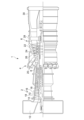
- FIG. 1 is a schematic configuration diagram of a gas turbine according to an embodiment.
- 2 is a schematic cross-sectional view of the combustor of FIG. 1;
- FIG. 3 is a schematic diagram of the fuel supply device of FIG. 2 .
- FIG. 1 is a configuration diagram of a gas turbine control device according to an embodiment.
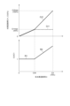
- FIG. 5 is a diagram showing an example of control of a first hydrogen mixing ratio and a second hydrogen mixing ratio, and a ratio of the two hydrogen mixing ratios with respect to a total hydrogen mixing ratio, performed by the gas turbine control device of FIG.
- FIG. 1 is a schematic diagram of a gas turbine 1 according to one embodiment.
- the gas turbine 1 includes a compressor 2 for generating compressed air as an oxidant, a combustor 4 for generating combustion gas using the compressed air and fuel, and a turbine 6 configured to be rotationally driven by the combustion gas.
- a generator (not shown) is connected to the turbine 6, and electricity is generated by the rotational energy of the turbine 6.
- the compressor 2 comprises a compressor casing 10, an air intake 12 provided on the inlet side of the compressor casing 10 for taking in air, a rotor 8 provided to penetrate both the compressor casing 10 and a turbine casing 22 described below, and various blades arranged inside the compressor casing 10.
- the various blades include an inlet guide vane 14 provided on the air intake 12 side, a plurality of stator vanes 16 fixed to the compressor casing 10 side, and a plurality of moving blades 18 planted on the rotor 8 so as to be arranged alternately with respect to the stator vanes 16.
- the compressor 2 may also include other components such as an air bleed chamber (not shown).
- air taken in from an air intake 12 passes through a number of stationary vanes 16 and a number of rotor blades 18 and is compressed to become high-temperature, high-pressure compressed air.
- the high-temperature, high-pressure compressed air is then sent from the compressor 2 to the downstream combustor 4.
- the combustor 4 is disposed within the casing 20.
- a plurality of combustors 4 may be disposed within the casing 20 in an annular shape centered around the rotor 8.
- the combustor 4 is supplied with fuel and compressed air generated by the compressor 2, and the fuel is combusted to generate combustion gas, which is the working fluid for the turbine 6.
- the combustion gas is then sent from the combustor 4 to the downstream turbine 6.
- the turbine 6 includes a turbine casing 22 and various blades arranged within the turbine casing 22.
- the various blades include a number of stationary vanes 24 fixed to the turbine casing 22 and a number of moving blades 26 attached to the rotor 8 so as to be arranged alternately with respect to the stationary vanes 24.
- the turbine 6 may also include other components such as outlet guide vanes.
- the rotor 8 is driven to rotate as the combustion gas passes through the number of stationary vanes 24 and the number of moving blades 26. This drives a generator connected to the rotor 8.
- the exhaust chamber 30 is connected to the downstream side of the turbine casing 22 via the exhaust casing 28.
- the combustion gases after driving the turbine 6 are exhausted to the outside via the exhaust casing 28 and the exhaust chamber 30.
- FIG. 2 is a schematic cross-sectional view of the combustor 4 in FIG. 1
- FIG. 3 is a schematic configuration diagram of the fuel supply device 70 in FIG. 2.
- the combustor 4 includes a combustor liner 46 provided in a combustor chamber 40 defined by a casing 20, a first fuel injection nozzle 50 for injecting a first fuel F1 in the combustor liner 46, and a second fuel injection nozzle 60 for injecting a second fuel F2 downstream of the first fuel injection nozzle 50.
- the first fuel injection nozzle 50 and the second fuel injection nozzle 60 are respectively supplied with a first fuel F1 and a second fuel F2 from a fuel supply device 70.
- the fuel supply device 70 can use hydrogen FH and natural gas FN, which is a fuel other than hydrogen, as fuel, and can adjust the hydrogen mixing ratio (the ratio of hydrogen FH to the total fuel) of the first fuel F1 and the second fuel F2 independently of each other.
- the fuel supply device 70 includes a hydrogen supply source 72 capable of supplying hydrogen FH and a natural gas supply source 74 capable of supplying natural gas FN.
- the hydrogen FH from the hydrogen supply source 72 can be supplied from a first hydrogen supply line 73 to the first fuel injection nozzle 50 and the second fuel injection nozzle 60 via a second hydrogen supply line 75 and a third hydrogen supply line 76.
- a first adjustment valve 80 is provided on the second hydrogen supply line 75 to adjust the amount of hydrogen FH supplied to the first fuel injection nozzle 50.
- a second adjustment valve 81 is provided on the third hydrogen supply line 76 to adjust the amount of hydrogen FH supplied to the second fuel injection nozzle 60.
- the openings of the first adjustment valve 80 and the second adjustment valve 81 are adjusted based on a control signal from the gas turbine control device 100, thereby adjusting the hydrogen mixing ratio of the first fuel F1 supplied to the first fuel injection nozzle 50 (hereinafter referred to as the "first hydrogen mixing ratio Cr1" as appropriate).
- the natural gas FN from the natural gas supply source 74 can be supplied from the first natural gas supply line 77 through the second natural gas supply line 78 and the third natural gas supply line 79 to the first fuel injection nozzle 50 and the second fuel injection nozzle 60, respectively.
- the second natural gas supply line 78 is provided with a third adjustment valve 82 for adjusting the amount of natural gas FN supplied to the first fuel injection nozzle 50.
- the third natural gas supply line 79 is provided with a fourth adjustment valve 83 for adjusting the amount of natural gas FN supplied to the second fuel injection nozzle 60.
- the openings of the third adjustment valve 82 and the fourth adjustment valve 83 are adjusted based on a control signal from the gas turbine control device 100, thereby adjusting the hydrogen mixing ratio of the second fuel F2 supplied to the second fuel injection nozzle 60 (hereinafter referred to as the "second hydrogen mixing ratio Cr2" as appropriate).
- the first fuel F1 injected from the first fuel injection nozzle 50 and the second fuel F2 injected from the second fuel injection nozzle 60 are mixed with the combustion air from the compressor 2 in the combustor liner 46 and combusted.
- the combustion gas generated by the combustion is supplied to the turbine 6 via the transition piece 48 connected downstream of the combustor liner 46.
- Figure 4 is a configuration diagram of the gas turbine control device 100 according to one embodiment.
- the gas turbine control device 100 is a control unit for controlling the gas turbine 1, and is composed of, for example, a CPU (Central Processing Unit), a RAM (Random Access Memory), a ROM (Read Only Memory), and a computer-readable storage medium.
- a series of processes for realizing various functions is stored in a storage medium, for example, in the form of a program, and the CPU reads this program into the RAM and executes information processing and arithmetic processing to realize various functions.
- the program may be pre-installed in a ROM or other storage medium, provided in a state stored in a computer-readable storage medium, or distributed via wired or wireless communication means.
- Computer-readable storage media include magnetic disks, optical magnetic disks, CD-ROMs, DVD-ROMs, and semiconductor memories.
- the gas turbine control device 100 includes a total fuel-mix ratio target value setting unit 102, a first hydrogen fuel-mix ratio control unit 104, and a second hydrogen fuel-mix ratio control unit 106.
- the total hydrogen combustion ratio target value setting unit 102 is configured to set a target value (hereinafter appropriately referred to as "total hydrogen combustion ratio target value Crt") for the total hydrogen combustion ratio Cr (the proportion of hydrogen FH in the total amount of the first fuel F1 supplied to the first fuel injection nozzle 50 and the second fuel F2 supplied to the second fuel injection nozzle 60).
- the first hydrogen combustion ratio control unit 104 is configured to control the first hydrogen combustion ratio Cr1 corresponding to the first fuel F1.
- the first hydrogen combustion ratio Cr1 is the hydrogen combustion ratio in the first fuel F1, and is an index showing the ratio of hydrogen FH to the entire first fuel F1.
- the first hydrogen combustion ratio control unit 104 controls the first hydrogen combustion ratio Cr1 as the ratio of hydrogen FH and natural gas FN in the first fuel F1 by adjusting the opening degree of the first adjustment valve 80 and the third adjustment valve 82.
- the second hydrogen combustion ratio control unit 106 is configured to control the second hydrogen combustion ratio Cr2 corresponding to the second fuel F2.
- the second hydrogen combustion ratio Cr2 is the hydrogen combustion ratio in the second fuel F2, and is an index showing the ratio of hydrogen FH to the entire second fuel F2.
- the second hydrogen combustion ratio control unit 106 controls the second hydrogen combustion ratio Cr2 as the ratio of hydrogen FH and natural gas FN in the second fuel F2 by adjusting the opening degree of the second adjustment valve 81 and the fourth adjustment valve 83.
- Figure 5 is a diagram showing an example of control of the first hydrogen mixing ratio Cr1 and the second hydrogen mixing ratio Cr2, and the ratio of the two hydrogen mixing ratios Cr2/Cr1, relative to the total hydrogen mixing ratio Cr, by the gas turbine control device 100 of Figure 4.
- the gas turbine control device 100 gradually increases the total hydrogen combustion ratio Cr, which is approximately zero in the initial state, to reach the total hydrogen combustion ratio target value Crt (>Crth) set by the total hydrogen combustion ratio target value setting unit 102.
- the first hydrogen combustion ratio control unit 104 and the second hydrogen combustion ratio control unit 106 increase the total hydrogen combustion ratio Cr so that the first hydrogen combustion ratio Cr1 is equal to or less than the second hydrogen combustion ratio Cr2. That is, in this range, the total hydrogen combustion ratio Cr is controlled to increase from zero toward the threshold value Crth while suppressing the first hydrogen combustion ratio Cr1 to be equal to or less than the second hydrogen combustion ratio Cr2. As a result, in the range where the total hydrogen combustion ratio Cr is relatively low, the first hydrogen combustion ratio Cr1 is suppressed to be equal to or less than the second hydrogen combustion ratio Cr2, thereby more reliably reducing the possibility of flame backflow, etc.
- the first hydrogen combustion ratio Cr1 is controlled to be equal to the second hydrogen combustion ratio Cr2 (i.e., the hydrogen combustion ratio ratio ratio Cr2/Cr1 is constant at approximately "1") throughout the entire range of the total hydrogen combustion ratio Cr from zero to less than the threshold value Crth.
- the first hydrogen combustion ratio Cr1 is suppressed to be equal to or less than the first maximum hydrogen combustion ratio Cr1max, while the second hydrogen combustion ratio Cr2 is controlled to be increased. This effectively reduces the possibility of flame backflow, etc. occurring due to the first hydrogen combustion ratio Cr1 corresponding to the first fuel F1 injected from the first fuel injection nozzle 50 arranged relatively upstream of the combustion chamber 4 becoming excessive when the total hydrogen combustion ratio Cr becomes relatively high.
- the total hydrogen combustion ratio Cr can be increased beyond the threshold value Crth to the total hydrogen combustion ratio target value Crt. In this way, it is possible to realize hydrogen combustion operation with a high hydrogen combustion ratio while suppressing flame backflow, etc.
- the first hydrogen combustion ratio Cr1 in the range where the total hydrogen combustion ratio Cr is greater than the threshold value Crth, the first hydrogen combustion ratio Cr1 is maintained constant at the first maximum hydrogen combustion ratio Cr1max regardless of the total hydrogen combustion ratio Cr.
- This first maximum hydrogen combustion ratio Cr1max is set to, for example, 40%.
- the first hydrogen combustion ratio Cr1 in the range where the total hydrogen combustion ratio Cr exceeds the threshold value Crth, the first hydrogen combustion ratio Cr1 can be increased to a maximum of 40% and cannot be increased any further. This effectively reduces the possibility of flame backflow, etc. occurring due to the first hydrogen combustion ratio Cr1 becoming excessively large.
- the second hydrogen mixing ratio Cr2 is limited to equal to or less than the second maximum hydrogen mixing ratio Cr2max.
- the second maximum hydrogen mixing ratio Cr2max is, for example, 100%.
- the first hydrogen mixing ratio Cr1 is restricted to equal to or less than the first maximum hydrogen mixing ratio Cr1max
- the second hydrogen mixing ratio Cr2 can be increased within the range in which it is equal to or less than the second maximum hydrogen mixing ratio Cr2max. This makes it possible to increase the total hydrogen mixing ratio Cr to a value higher than before while preventing flame backflow, etc.
- the total hydrogen combustion ratio Cr can be increased to 70% by increasing the second hydrogen combustion ratio Cr2 to 100% while maintaining the first hydrogen combustion ratio Cr1 at 40%.
- the first hydrogen combustion ratio Cr1 corresponding to the first fuel F1 injected from the first fuel injection nozzle 50 arranged relatively upstream of the combustion chamber is limited to the first maximum hydrogen combustion ratio Cr1max or less. This effectively reduces the possibility of flame backflow, etc. occurring due to the first hydrogen combustion ratio Cr1 being excessive.
- the second hydrogen combustion ratio Cr2 corresponding to the second fuel F2 injected from the second fuel injection nozzle 60 arranged relatively downstream of the combustion chamber the total hydrogen combustion ratio Cr is increased beyond the threshold value Crth to the total hydrogen combustion ratio target value Crt. In this way, it is possible to realize hydrogen combustion operation with a high hydrogen combustion ratio while suppressing flame backflow, etc.
- a method for operating a gas turbine includes the steps of: 1.
- the first hydrogen combustion ratio corresponding to the first fuel injected from the first fuel injection nozzle located relatively upstream of the combustion chamber is limited to equal to or less than the first maximum hydrogen combustion ratio. This effectively reduces the possibility of flame backflow or the like occurring due to an excessive hydrogen combustion ratio of the first fuel.
- the second hydrogen combustion ratio corresponding to the second fuel injected from the second fuel injection nozzle located relatively downstream of the combustion chamber is increased beyond the threshold value to the total hydrogen combustion ratio target value. In this way, it is possible to realize hydrogen combustion operation with a high hydrogen combustion ratio while suppressing flame backflow or the like.
- the first hydrogen combustion ratio is maintained constant so as to be equal to or less than the first maximum hydrogen combustion ratio. This effectively reduces the possibility of flame backflow or the like occurring due to an excessively large hydrogen combustion ratio of the first fuel.
- the first hydrogen mixing ratio is equal to or less than the second hydrogen mixing ratio.
- the first hydrogen combustion ratio is adjusted to be equal to or less than the second hydrogen combustion ratio.
- the first hydrogen combustion ratio may be equal to the second hydrogen combustion ratio.
- the first hydrogen combustion ratio and the second hydrogen combustion ratio are adjusted so that there is a time when the first hydrogen combustion ratio is equal to the second hydrogen combustion ratio.
- the first maximum hydrogen co-firing ratio is 40%.
- the first maximum hydrogen combustion ratio which is the upper limit of the first hydrogen combustion ratio, is set to 40%. This effectively reduces the possibility of flame backflow, etc. occurring due to the first hydrogen combustion ratio becoming excessive.
- any one of the above (1) to (5) When the total hydrogen combustion ratio corresponding to all fuels supplied to the combustor is increased to a predetermined total hydrogen combustion ratio target value, if the total hydrogen combustion ratio is equal to or greater than a threshold value, the second hydrogen combustion ratio is limited to be equal to or less than a second maximum hydrogen combustion ratio.
- the second hydrogen combustion ratio is variably controlled within a range limited to be equal to or less than the second maximum hydrogen combustion ratio, so that the total hydrogen combustion ratio can be adjusted to the target total hydrogen combustion ratio.
- the second maximum hydrogen co-firing ratio is 100%.
- the second maximum hydrogen combustion ratio which is the upper limit of the second hydrogen combustion ratio
- the maximum target total hydrogen co-firing ratio is 70%.
Landscapes
- Engineering & Computer Science (AREA)
- Chemical & Material Sciences (AREA)
- Combustion & Propulsion (AREA)
- Mechanical Engineering (AREA)
- General Engineering & Computer Science (AREA)
- Regulation And Control Of Combustion (AREA)
Priority Applications (3)
| Application Number | Priority Date | Filing Date | Title |
|---|---|---|---|
| CN202480037630.8A CN121358990A (zh) | 2023-08-04 | 2024-07-11 | 燃气涡轮机的运行方法 |
| JP2025539224A JPWO2025033090A1 (https=) | 2023-08-04 | 2024-07-11 | |
| KR1020257042641A KR20260013977A (ko) | 2023-08-04 | 2024-07-11 | 가스 터빈의 운전 방법 |
Applications Claiming Priority (2)
| Application Number | Priority Date | Filing Date | Title |
|---|---|---|---|
| JP2023-128011 | 2023-08-04 | ||
| JP2023128011 | 2023-08-04 |
Publications (1)
| Publication Number | Publication Date |
|---|---|
| WO2025033090A1 true WO2025033090A1 (ja) | 2025-02-13 |
Family
ID=94534028
Family Applications (1)
| Application Number | Title | Priority Date | Filing Date |
|---|---|---|---|
| PCT/JP2024/025054 Pending WO2025033090A1 (ja) | 2023-08-04 | 2024-07-11 | ガスタービンの運転方法 |
Country Status (4)
| Country | Link |
|---|---|
| JP (1) | JPWO2025033090A1 (https=) |
| KR (1) | KR20260013977A (https=) |
| CN (1) | CN121358990A (https=) |
| WO (1) | WO2025033090A1 (https=) |
Citations (5)
| Publication number | Priority date | Publication date | Assignee | Title |
|---|---|---|---|---|
| JP2011075174A (ja) * | 2009-09-30 | 2011-04-14 | Hitachi Ltd | 水素含有燃料対応燃焼器および、その低NOx運転方法 |
| WO2014092185A1 (ja) * | 2012-12-13 | 2014-06-19 | 川崎重工業株式会社 | マルチ燃料対応のガスタービン燃焼器 |
| CN112228906A (zh) * | 2020-09-27 | 2021-01-15 | 西安交通大学 | 一种燃气轮机的氢气喷射系统及稳焰方法 |
| JP2023066375A (ja) * | 2021-10-28 | 2023-05-15 | ゼネラル・エレクトリック・カンパニイ | ターボ機械燃焼器を水素で運転する方法 |
| WO2023140183A1 (ja) * | 2022-01-20 | 2023-07-27 | 三菱重工業株式会社 | ガスタービン燃焼器の制御方法及びガスタービン燃焼器の制御装置 |
-
2024
- 2024-07-11 JP JP2025539224A patent/JPWO2025033090A1/ja active Pending
- 2024-07-11 CN CN202480037630.8A patent/CN121358990A/zh active Pending
- 2024-07-11 KR KR1020257042641A patent/KR20260013977A/ko active Pending
- 2024-07-11 WO PCT/JP2024/025054 patent/WO2025033090A1/ja active Pending
Patent Citations (5)
| Publication number | Priority date | Publication date | Assignee | Title |
|---|---|---|---|---|
| JP2011075174A (ja) * | 2009-09-30 | 2011-04-14 | Hitachi Ltd | 水素含有燃料対応燃焼器および、その低NOx運転方法 |
| WO2014092185A1 (ja) * | 2012-12-13 | 2014-06-19 | 川崎重工業株式会社 | マルチ燃料対応のガスタービン燃焼器 |
| CN112228906A (zh) * | 2020-09-27 | 2021-01-15 | 西安交通大学 | 一种燃气轮机的氢气喷射系统及稳焰方法 |
| JP2023066375A (ja) * | 2021-10-28 | 2023-05-15 | ゼネラル・エレクトリック・カンパニイ | ターボ機械燃焼器を水素で運転する方法 |
| WO2023140183A1 (ja) * | 2022-01-20 | 2023-07-27 | 三菱重工業株式会社 | ガスタービン燃焼器の制御方法及びガスタービン燃焼器の制御装置 |
Also Published As
| Publication number | Publication date |
|---|---|
| CN121358990A (zh) | 2026-01-16 |
| JPWO2025033090A1 (https=) | 2025-02-13 |
| KR20260013977A (ko) | 2026-01-29 |
Similar Documents
| Publication | Publication Date | Title |
|---|---|---|
| US8127557B2 (en) | Control systems and method for controlling a load point of a gas turbine engine | |
| US9631559B2 (en) | Fuel control method and fuel control apparatus for gas turbine and gas turbine | |
| CN106762158B (zh) | 用于操作燃气涡轮的同时维持排放标准的系统和方法 | |
| JP2007505261A (ja) | 多軸タービン発電機システム及び制御方法 | |
| US20130327050A1 (en) | Controlling flame stability of a gas turbine generator | |
| JP2014109276A (ja) | ターンダウンモードでガスタービンを運転するシステム及び方法 | |
| US9523313B2 (en) | System and method for loading a combined cycle power plant | |
| US20150322861A1 (en) | Enhanced Turbine Cooling System Using a Blend of Compressor Bleed Air and Ambient Air | |
| JP2008274928A (ja) | 保炎マージンの範囲内で作動させるのを可能にするための方法及びシステム | |
| AU2016254323B2 (en) | Ultra-low NOx emission gas turbine engine in mechanical drive applications | |
| WO2025033090A1 (ja) | ガスタービンの運転方法 | |
| JP7012863B2 (ja) | 複合サイクル型発電装置のガスタービンエンジンの始動方法 | |
| JP7780037B2 (ja) | ガスタービンの運転方法 | |
| KR102912290B1 (ko) | 가스 터빈 시스템 및 그 제어 방법 | |
| JP6740375B2 (ja) | 排気を減らすための選択的燃焼器制御の方法 | |
| US20260071565A1 (en) | Hot scr tempering air system for gas turbine part load efficiency and extended turndown | |
| CN111623372B (zh) | 运行顺序燃烧器的方法和包括顺序燃烧器的燃气涡轮 | |
| WO2024202455A1 (ja) | ガスタービン制御装置 | |
| JP2025136196A (ja) | ガスタービン起動方法、及び、ガスタービン | |
| WO2024116966A1 (ja) | ガスタービンの運転方法 | |
| KR20250122863A (ko) | 암모니아 혼소 가스터빈 시스템 | |
| CN121139165A (zh) | 一种燃气轮机多燃料基准实时表决调度方法 | |
| CN118871717A (zh) | 燃烧系统 |
Legal Events
| Date | Code | Title | Description |
|---|---|---|---|
| 121 | Ep: the epo has been informed by wipo that ep was designated in this application |
Ref document number: 24851519 Country of ref document: EP Kind code of ref document: A1 |
|
| ENP | Entry into the national phase |
Ref document number: 1020257042641 Country of ref document: KR Free format text: ST27 STATUS EVENT CODE: A-0-1-A10-A15-NAP-PA0105 (AS PROVIDED BY THE NATIONAL OFFICE) |
|
| WWE | Wipo information: entry into national phase |
Ref document number: 1020257042641 Country of ref document: KR |
|
| ENP | Entry into the national phase |
Ref document number: 2025539224 Country of ref document: JP Kind code of ref document: A |
|
| WWE | Wipo information: entry into national phase |
Ref document number: 2025539224 Country of ref document: JP |
|
| WWP | Wipo information: published in national office |
Ref document number: 1020257042641 Country of ref document: KR |