WO2025032945A1 - センサ診断システムおよびセンサ診断方法 - Google Patents
センサ診断システムおよびセンサ診断方法 Download PDFInfo
- Publication number
- WO2025032945A1 WO2025032945A1 PCT/JP2024/020832 JP2024020832W WO2025032945A1 WO 2025032945 A1 WO2025032945 A1 WO 2025032945A1 JP 2024020832 W JP2024020832 W JP 2024020832W WO 2025032945 A1 WO2025032945 A1 WO 2025032945A1
- Authority
- WO
- WIPO (PCT)
- Prior art keywords
- sensor
- train
- determination unit
- abnormality
- abnormality determination
- Prior art date
- Legal status (The legal status is an assumption and is not a legal conclusion. Google has not performed a legal analysis and makes no representation as to the accuracy of the status listed.)
- Pending
Links
Images


Classifications
-
- B—PERFORMING OPERATIONS; TRANSPORTING
- B60—VEHICLES IN GENERAL
- B60L—PROPULSION OF ELECTRICALLY-PROPELLED VEHICLES; SUPPLYING ELECTRIC POWER FOR AUXILIARY EQUIPMENT OF ELECTRICALLY-PROPELLED VEHICLES; ELECTRODYNAMIC BRAKE SYSTEMS FOR VEHICLES IN GENERAL; MAGNETIC SUSPENSION OR LEVITATION FOR VEHICLES; MONITORING OPERATING VARIABLES OF ELECTRICALLY-PROPELLED VEHICLES; ELECTRIC SAFETY DEVICES FOR ELECTRICALLY-PROPELLED VEHICLES
- B60L3/00—Electric devices on electrically-propelled vehicles for safety purposes; Monitoring operating variables, e.g. speed, deceleration or energy consumption
- B60L3/08—Means for preventing excessive speed of the vehicle
-
- B—PERFORMING OPERATIONS; TRANSPORTING
- B61—RAILWAYS
- B61L—GUIDING RAILWAY TRAFFIC; ENSURING THE SAFETY OF RAILWAY TRAFFIC
- B61L25/00—Recording or indicating positions or identities of vehicles or trains or setting of track apparatus
- B61L25/02—Indicating or recording positions or identities of vehicles or trains
- B61L25/04—Indicating or recording train identities
Definitions
- the present invention relates to a sensor diagnostic system and a sensor diagnostic method for detecting abnormalities in a sensor.
- unmanned operation requires a mechanism for automatically detecting obstacles on the route, and methods using sensors such as millimeter wave radar, LiDAR, and cameras are being researched. Obstacle detection depends on the performance of the sensors mentioned above, and there is an issue that if some kind of abnormality occurs and the sensor is no longer able to perform as expected, it will no longer be able to detect obstacles. Therefore, to ensure the safety of train operations, it is necessary to be able to detect abnormalities in the sensors.
- Patent Document 1 discloses a technology for detecting abnormalities in a sensor, which has a database that records the installation positions and installation identifiers of ground-based objects, identifies the installation identifier from sensor information that includes information detected by the sensor, and refers to the database. It also discloses a configuration that calculates an accuracy-guaranteed detection distance as a sensor's accuracy-guaranteed performance, and uses the calculated detection distance to determine whether the sensor is faulty.
- the objective of this invention is to provide technology that prevents degradation of performance due to train position or external factors from being interpreted as a sensor abnormality, enabling stable train operation.
- one representative sensor diagnostic system of the present invention is a sensor diagnostic system that evaluates the performance of a sensor mounted on a train, and includes a database that stores information on existing equipment that can be detected by the sensor according to the train's position, a train control unit that detects the train's position, and a sensor anomaly determination unit that determines that there is an abnormality in the sensor if the state of the existing equipment detected by the sensor at the train's position detected by the train control unit does not match the information on the existing equipment stored in the database.
- FIG. 1 is a diagram showing an outline of a sensor diagnostic system according to a first embodiment of the present invention.
- FIG. 2 is a diagram showing the configuration of the on-board control device of the first embodiment.
- FIG. 3 is a diagram illustrating an example of a data configuration of the detected object DB according to the first embodiment.
- FIG. 4 is a diagram illustrating a process flow of sensor abnormality detection according to the first embodiment.
- FIG. 5 is a diagram showing an outline of a sensor diagnostic system according to a second embodiment of the present invention.
- FIG. 6 is a diagram illustrating an example of a data configuration of a detected object DB according to the second embodiment.
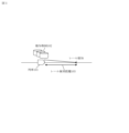
- FIG. 1 shows an overview of the sensor diagnostic system in the first embodiment of the present invention.
- FIG. 2 shows the configuration of the on-board control device 201 mounted on the train 101. The operation of the on-board control device 201 shown in FIG. 2 will be explained using FIG. 1. The explanation will be given using an example in which rails are targeted as existing detectable equipment. "Existing equipment” refers to existing equipment installed along the railway line, and in addition to rails, possible examples include signals, tool boxes, etc.
- the train 101 detects the rails using the sensor 203.
- a camera is used as the sensor 203, and the rails are detected by image processing of the image captured by the sensor 203.
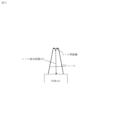
- the sensor control unit 204 detects the rails by image processing of the image input from the sensor 203, and can calculate the length of the detected rail as the rail detection distance 103. Assuming that the rails are installed on a flat surface, the rail position in three-dimensional space can be analyzed from the two-dimensional image, and the length of the rail shown in the two-dimensional image, that is, the rail detection distance, can be calculated geometrically.
- the detected object DB 102 is a database in which the length of the rail that can be detected at the position of the train 101, that is, the rail detectable distance, is stored. Three databases, morning, afternoon, and night, are created in advance according to the time of day when the train 101 runs. One of the three DBs is selected as the detected object DB 102 to be used according to the time of day when the train 101 runs.
- the sensor abnormality determination unit 202 receives the train position from the train control unit 205, refers to the detected object DB 102 at the received train position, and obtains the rail detectable distance at the current position. After obtaining the rail detectable distance, the sensor abnormality determination unit 202 compares the rail detectable distance with the rail detection distance 103 calculated by the sensor control unit 204, and can determine that there is a sensor abnormality if the rail detection distance 103 is shorter than the rail detectable distance by more than a predetermined value. However, at a train position where the rail shape is curved, when passing an oncoming train, the oncoming train may become an obstacle and the rail beyond the curve may not be visible, resulting in a shorter rail detection distance 103.
- the rail detection distance 103 may be shortened due to installations on the ground, but in such a case, the rail detection distance in the detected object DB 102 at the train position will also be shortened, so this does not pose a problem.
- FIG. 3 An example of the data configuration of the detected object DB 102 is shown in Figure 3. Since it is expected that the rail detectable distance will differ between the upbound and downbound directions, a detected object DB 102 will be created for each direction, and Figure 3 shows an example for the downbound direction.
- “Position” refers to the distance in kilometers of the position of the train 101, and refers to the starting point where the rail detectable distance changes.
- "Detectable distance” is the rail detectable distance at that position. Therefore, for example, in Figure 3, the rail detectable distance for a train position of 300m to 400m is 200m.
- the data for the detected object DB 102 can be created in advance, for example by statistically processing the detection results of the sensor 203 when the train has run repeatedly in advance.
- FIG. 4 shows the process flow for the sensor abnormality determination unit 202 to determine a sensor abnormality.
- the sensor abnormality determination unit 202 periodically performs the process shown in FIG. 4.
- Step 401 The sensor abnormality determination unit 202 acquires the rail detection distance 103 currently detected by the sensor 203 from the sensor control unit 204. At this time, the sensor control unit 204 also performs image processing to determine whether the rail shape is straight or curved, and to determine the presence or absence of an oncoming train, and the sensor abnormality determination unit 202 acquires each of these results from the sensor control unit 204.
- Step 402 The sensor abnormality determination unit 202 acquires the current train position from the train control unit 205, and uses the acquired train position to refer to the detected object DB 102 to acquire the rail detectable distance at the current position.
- Step 403 The sensor anomaly determination unit 202, based on the results of the determination of whether the rail shape is straight or curved and the presence or absence of an oncoming train acquired in step 401, ends the process without performing sensor diagnosis if the rail shape is curved and there is an oncoming train. If the rail shape is not curved or there is no oncoming train, the process proceeds to step 404 to perform sensor diagnosis.
- Step 404 The sensor abnormality determination unit 202 compares the rail detection distance 103 acquired in step 401 with the rail detectable distance acquired in step 402, and determines whether the rail detection distance 103 is shorter than the rail detectable distance by a predetermined value or more. If it is shorter, the process proceeds to step 405. If it is not shorter, it is determined that there is no abnormality in the sensor, and the process ends.
- Step 405 The sensor abnormality determination unit 202 determines that the sensor is abnormal and executes a predetermined abnormality process.
- the abnormality process may be, for example, braking output when the train is unable to run, or only an alarm output when the train can continue to run.
- the process may be determined in advance taking into account the importance of the sensor abnormality.
- the above process allows the system to determine sensor abnormalities while taking external factors into account by selecting the database to be referenced depending on the state of external factors.
- the database By appropriately selecting the database, it is possible to prevent degradation of sensor performance due to the surrounding environment from being determined as a sensor abnormality, enabling stable train operation to be achieved.
- three databases are created: morning, afternoon, and evening, and a database is selected based on the time of day.
- a configuration is also possible in which the database is selected based on the illuminance around the train rather than the time of day.
- the illuminance at the time each database was created is recorded in the three databases, and a illuminance meter is connected to the on-board control device 201.
- the sensor abnormality determination unit 202 inputs the illuminance around the train from the illuminance meter, compares the current illuminance input with the illuminance recorded in each database, and selects the database with the closest illuminance.
- the sensor can be correctly diagnosed even if the surrounding illuminance changes due to factors other than the time of day, such as weather.
- the system can interpolate values from multiple databases to calculate the rail detectable distance at the current position.
- a database with an illuminance higher than the current illuminance and a database with an illuminance lower than the current illuminance are referenced to obtain the rail detectable distance at each current position.
- the two obtained rail detectable distances are interpolated to calculate the rail detectable distance at the current position at the current illuminance. Interpolation makes it possible to detect sensor abnormalities with greater accuracy.
- sensors other than cameras can also be diagnosed in the same way as long as they can detect rails.
- sensors other than cameras can also be diagnosed in the same way as long as they can detect rails.
- infrared cameras, LiDAR, and millimeter wave radar can also be diagnosed with the configuration in this embodiment. Since it is expected that the rail detection distance 103 will differ depending on the sensor, when diagnosing multiple sensors, a separate detected object DB 102 is created for each sensor.
- the detection object DB 102 may be created and selected according to the characteristics of the sensor.
- the sensor performance changes with changes in the ambient temperature, so multiple detection object DBs 102 with different ambient temperatures may be created, a thermometer may be connected to the on-board control device 201, and the database to be used may be selected according to the ambient temperature. This allows the infrared camera to be used as a sensor.
- the performance decreases with rain, so multiple detection object DBs 102 with different amounts of rainfall may be created, a rain gauge may be connected to the on-board control device 201, and the database to be used may be selected according to the amount of rainfall.
- the LiDAR to be used as a sensor.
- the image from the camera is affected not only by the illuminance, but also by weather such as rain and snow.
- a detection object DB 102 may be created for each combination of illuminance and weather. Then, the database to be used may be selected according to the illuminance and weather. The weather may be input by the driver.
- FIG. 5 shows an overview of a sensor diagnosis system in Example 2 of the present invention.
- the sensor was diagnosed using the rail length detected from the camera image, but in this example, a configuration is shown in which the sensor is diagnosed using the rail-to-rail distance.
- the accuracy of sensor diagnosis is improved.
- the data in the detected object DB 102, the sensor control unit 204, and the sensor abnormality determination unit 202 are changed.
- the sensor control unit 204 can calculate the position of the rail detection distance, that is, the rail distance at the end of the rail detected by the sensor, in addition to the rail detection distance 103.
- the rail distance at the rail detection distance can be calculated using a pinhole camera model based on the relationship between the rail detection distance and the focal length of the lens.
- the sensor abnormality determination unit 202 in this embodiment acquires the rail detection distance 103 and the rail distance from the sensor control unit 204.
- the sensor abnormality determination unit 202 performs the same determination process as in the first embodiment for the rail detection distance 103 and diagnoses the sensor. If no sensor abnormality is detected in the rail detection distance 103, the sensor can be further diagnosed based on the rail distance.
- the gauge Since the true value of the rail distance is known as the gauge, it is determined whether the rail distance calculated by the sensor control unit 204 is within the error of the rail distance at the train position stored in the detected object DB 102, and if it is equal to or greater than the error stored in the detected object DB 102, it is determined that there is a sensor abnormality.
- each of the above-mentioned configurations, functions, processing units, processing means, etc. may be realized in hardware by designing a part or all of them as an integrated circuit, for example.
- each of the above-mentioned configurations, functions, etc. may be realized in software by a processor interpreting and executing a program that realizes each function.
- Information such as programs, tables, files, etc. that realize each function can be stored in a memory, a recording device such as a hard disk or SSD (Solid State Drive), or a recording medium such as an IC card, SD card, or DVD.
Landscapes
- Engineering & Computer Science (AREA)
- Mechanical Engineering (AREA)
- Life Sciences & Earth Sciences (AREA)
- Sustainable Development (AREA)
- Sustainable Energy (AREA)
- Power Engineering (AREA)
- Transportation (AREA)
- Electric Propulsion And Braking For Vehicles (AREA)
- Train Traffic Observation, Control, And Security (AREA)
Applications Claiming Priority (2)
| Application Number | Priority Date | Filing Date | Title |
|---|---|---|---|
| JP2023-127550 | 2023-08-04 | ||
| JP2023127550A JP2025023438A (ja) | 2023-08-04 | 2023-08-04 | センサ診断システムおよびセンサ診断方法 |
Publications (1)
| Publication Number | Publication Date |
|---|---|
| WO2025032945A1 true WO2025032945A1 (ja) | 2025-02-13 |
Family
ID=94534215
Family Applications (1)
| Application Number | Title | Priority Date | Filing Date |
|---|---|---|---|
| PCT/JP2024/020832 Pending WO2025032945A1 (ja) | 2023-08-04 | 2024-06-07 | センサ診断システムおよびセンサ診断方法 |
Country Status (2)
| Country | Link |
|---|---|
| JP (1) | JP2025023438A (https=) |
| WO (1) | WO2025032945A1 (https=) |
Cited By (1)
| Publication number | Priority date | Publication date | Assignee | Title |
|---|---|---|---|---|
| US20240034371A1 (en) * | 2019-10-18 | 2024-02-01 | Hitachi, Ltd. | Sensor performance evaluation system and method, and automatic driving system |
Citations (4)
| Publication number | Priority date | Publication date | Assignee | Title |
|---|---|---|---|---|
| JP2017140981A (ja) * | 2016-02-12 | 2017-08-17 | 株式会社デンソー | 車両用装置 |
| JP2021015454A (ja) * | 2019-07-12 | 2021-02-12 | 日立オートモティブシステムズ株式会社 | 車載制御システム及び車両制御方法 |
| JP2022145230A (ja) * | 2021-03-19 | 2022-10-03 | 株式会社日立製作所 | 障害物検知支援システム |
| JP2023089473A (ja) * | 2021-12-16 | 2023-06-28 | 株式会社日立製作所 | 列車制御システムおよび列車制御方法 |
-
2023
- 2023-08-04 JP JP2023127550A patent/JP2025023438A/ja active Pending
-
2024
- 2024-06-07 WO PCT/JP2024/020832 patent/WO2025032945A1/ja active Pending
Patent Citations (4)
| Publication number | Priority date | Publication date | Assignee | Title |
|---|---|---|---|---|
| JP2017140981A (ja) * | 2016-02-12 | 2017-08-17 | 株式会社デンソー | 車両用装置 |
| JP2021015454A (ja) * | 2019-07-12 | 2021-02-12 | 日立オートモティブシステムズ株式会社 | 車載制御システム及び車両制御方法 |
| JP2022145230A (ja) * | 2021-03-19 | 2022-10-03 | 株式会社日立製作所 | 障害物検知支援システム |
| JP2023089473A (ja) * | 2021-12-16 | 2023-06-28 | 株式会社日立製作所 | 列車制御システムおよび列車制御方法 |
Cited By (2)
| Publication number | Priority date | Publication date | Assignee | Title |
|---|---|---|---|---|
| US20240034371A1 (en) * | 2019-10-18 | 2024-02-01 | Hitachi, Ltd. | Sensor performance evaluation system and method, and automatic driving system |
| US12384434B2 (en) * | 2019-10-18 | 2025-08-12 | Hitachi, Ltd. | Sensor performance evaluation system and method, and automatic driving system |
Also Published As
| Publication number | Publication date |
|---|---|
| JP2025023438A (ja) | 2025-02-17 |
Similar Documents
| Publication | Publication Date | Title |
|---|---|---|
| US12112554B2 (en) | Method for determining a drivable area | |
| US10532740B2 (en) | Method and arrangement for monitoring and adapting the performance of a fusion system of an autonomous vehicle | |
| US11787424B2 (en) | Method for checking at least one driving environment sensor of a vehicle | |
| EP2922033B1 (en) | A vehicle sensor diagnosis system and method and a vehicle comprising such a system | |
| JP2020104547A (ja) | 外界センサの故障検出装置、及び、外界センサの故障検出方法 | |
| JP7016276B2 (ja) | 列車位置推定装置 | |
| US10845806B2 (en) | Autonomous vehicle control using prior radar space map | |
| AU2020366769B2 (en) | Sensor performance evaluation system and method, and automatic driving system | |
| JP7419359B2 (ja) | 異常診断装置 | |
| US10345196B2 (en) | Vehicle sensor system | |
| WO2025032945A1 (ja) | センサ診断システムおよびセンサ診断方法 | |
| AU2022412197B2 (en) | Train control system and train control method | |
| CN114475656A (zh) | 行驶轨迹预测方法、装置、电子设备以及存储介质 | |
| US20200143173A1 (en) | Route inspection system | |
| US20240400042A1 (en) | Autonomous Vehicle And Method Of Controlling | |
| JP2022115635A (ja) | 走行軌跡推定システム、走行軌跡推定プログラム、及び走行軌跡推定方法 | |
| US11237081B2 (en) | Vehicle sensor system | |
| CN114217601A (zh) | 自驾车的混合决策方法及其系统 | |
| KR20260017958A (ko) | 윈드실드 와이퍼 마모를 예측하는 시스템 및 방법 | |
| CN119968301A (zh) | 用于检测自动驾驶车辆传感器故障的基于云的扫描 | |
| JP6851111B2 (ja) | 踏切障害物検知装置 | |
| CN116045992B (zh) | 自动驾驶车辆的导航方法、装置及电子设备、存储介质 | |
| KR20250059601A (ko) | 객체 인식 장치 및 그 방법 | |
| JPWO2019116537A1 (ja) | 情報取得方法、情報取得装置、車載装置、路上センサ装置、及び情報取得システム | |
| US20240144752A1 (en) | Vehicle inspection system and vehicle inspection method |
Legal Events
| Date | Code | Title | Description |
|---|---|---|---|
| 121 | Ep: the epo has been informed by wipo that ep was designated in this application |
Ref document number: 24850347 Country of ref document: EP Kind code of ref document: A1 |
|
| NENP | Non-entry into the national phase |
Ref country code: DE |