EP3232285A1 - Method and arrangement for monitoring and adapting the performance of a fusion system of an autonomous vehicle - Google Patents
Method and arrangement for monitoring and adapting the performance of a fusion system of an autonomous vehicle Download PDFInfo
- Publication number
- EP3232285A1 EP3232285A1 EP16165223.5A EP16165223A EP3232285A1 EP 3232285 A1 EP3232285 A1 EP 3232285A1 EP 16165223 A EP16165223 A EP 16165223A EP 3232285 A1 EP3232285 A1 EP 3232285A1
- Authority
- EP
- European Patent Office
- Prior art keywords
- fusion system
- determination
- drivable area
- localization
- adapting
- Prior art date
- Legal status (The legal status is an assumption and is not a legal conclusion. Google has not performed a legal analysis and makes no representation as to the accuracy of the status listed.)
- Granted
Links
- 230000004927 fusion Effects 0.000 title claims abstract description 113
- 238000000034 method Methods 0.000 title claims abstract description 37
- 238000012544 monitoring process Methods 0.000 title claims abstract description 25
- 230000004807 localization Effects 0.000 claims abstract description 54
- 230000006870 function Effects 0.000 claims abstract description 42
- 230000007613 environmental effect Effects 0.000 claims abstract description 21
- 230000008447 perception Effects 0.000 claims abstract description 21
- 230000000704 physical effect Effects 0.000 claims abstract description 12
- 230000000977 initiatory effect Effects 0.000 claims description 10
- 230000001133 acceleration Effects 0.000 claims description 4
- 230000006978 adaptation Effects 0.000 description 2
- 238000011156 evaluation Methods 0.000 description 2
- 238000012545 processing Methods 0.000 description 2
- 238000013500 data storage Methods 0.000 description 1
- 230000001419 dependent effect Effects 0.000 description 1
- 238000013461 design Methods 0.000 description 1
- 239000012634 fragment Substances 0.000 description 1
- 230000001737 promoting effect Effects 0.000 description 1
- 230000000717 retained effect Effects 0.000 description 1
- 238000006467 substitution reaction Methods 0.000 description 1
Images

Classifications
-
- G—PHYSICS
- G05—CONTROLLING; REGULATING
- G05D—SYSTEMS FOR CONTROLLING OR REGULATING NON-ELECTRIC VARIABLES
- G05D1/00—Control of position, course or altitude of land, water, air, or space vehicles, e.g. automatic pilot
- G05D1/02—Control of position or course in two dimensions
- G05D1/021—Control of position or course in two dimensions specially adapted to land vehicles
- G05D1/0231—Control of position or course in two dimensions specially adapted to land vehicles using optical position detecting means
- G05D1/0246—Control of position or course in two dimensions specially adapted to land vehicles using optical position detecting means using a video camera in combination with image processing means
- G05D1/0253—Control of position or course in two dimensions specially adapted to land vehicles using optical position detecting means using a video camera in combination with image processing means extracting relative motion information from a plurality of images taken successively, e.g. visual odometry, optical flow
-
- B—PERFORMING OPERATIONS; TRANSPORTING
- B60—VEHICLES IN GENERAL
- B60W—CONJOINT CONTROL OF VEHICLE SUB-UNITS OF DIFFERENT TYPE OR DIFFERENT FUNCTION; CONTROL SYSTEMS SPECIALLY ADAPTED FOR HYBRID VEHICLES; ROAD VEHICLE DRIVE CONTROL SYSTEMS FOR PURPOSES NOT RELATED TO THE CONTROL OF A PARTICULAR SUB-UNIT
- B60W30/00—Purposes of road vehicle drive control systems not related to the control of a particular sub-unit, e.g. of systems using conjoint control of vehicle sub-units, or advanced driver assistance systems for ensuring comfort, stability and safety or drive control systems for propelling or retarding the vehicle
- B60W30/08—Active safety systems predicting or avoiding probable or impending collision or attempting to minimise its consequences
- B60W30/095—Predicting travel path or likelihood of collision
-
- B—PERFORMING OPERATIONS; TRANSPORTING
- B60—VEHICLES IN GENERAL
- B60W—CONJOINT CONTROL OF VEHICLE SUB-UNITS OF DIFFERENT TYPE OR DIFFERENT FUNCTION; CONTROL SYSTEMS SPECIALLY ADAPTED FOR HYBRID VEHICLES; ROAD VEHICLE DRIVE CONTROL SYSTEMS FOR PURPOSES NOT RELATED TO THE CONTROL OF A PARTICULAR SUB-UNIT
- B60W40/00—Estimation or calculation of non-directly measurable driving parameters for road vehicle drive control systems not related to the control of a particular sub unit, e.g. by using mathematical models
- B60W40/02—Estimation or calculation of non-directly measurable driving parameters for road vehicle drive control systems not related to the control of a particular sub unit, e.g. by using mathematical models related to ambient conditions
- B60W40/04—Traffic conditions
-
- B—PERFORMING OPERATIONS; TRANSPORTING
- B60—VEHICLES IN GENERAL
- B60W—CONJOINT CONTROL OF VEHICLE SUB-UNITS OF DIFFERENT TYPE OR DIFFERENT FUNCTION; CONTROL SYSTEMS SPECIALLY ADAPTED FOR HYBRID VEHICLES; ROAD VEHICLE DRIVE CONTROL SYSTEMS FOR PURPOSES NOT RELATED TO THE CONTROL OF A PARTICULAR SUB-UNIT
- B60W50/00—Details of control systems for road vehicle drive control not related to the control of a particular sub-unit, e.g. process diagnostic or vehicle driver interfaces
- B60W50/08—Interaction between the driver and the control system
- B60W50/14—Means for informing the driver, warning the driver or prompting a driver intervention
-
- B—PERFORMING OPERATIONS; TRANSPORTING
- B60—VEHICLES IN GENERAL
- B60W—CONJOINT CONTROL OF VEHICLE SUB-UNITS OF DIFFERENT TYPE OR DIFFERENT FUNCTION; CONTROL SYSTEMS SPECIALLY ADAPTED FOR HYBRID VEHICLES; ROAD VEHICLE DRIVE CONTROL SYSTEMS FOR PURPOSES NOT RELATED TO THE CONTROL OF A PARTICULAR SUB-UNIT
- B60W60/00—Drive control systems specially adapted for autonomous road vehicles
- B60W60/005—Handover processes
- B60W60/0053—Handover processes from vehicle to occupant
-
- B—PERFORMING OPERATIONS; TRANSPORTING
- B60—VEHICLES IN GENERAL
- B60W—CONJOINT CONTROL OF VEHICLE SUB-UNITS OF DIFFERENT TYPE OR DIFFERENT FUNCTION; CONTROL SYSTEMS SPECIALLY ADAPTED FOR HYBRID VEHICLES; ROAD VEHICLE DRIVE CONTROL SYSTEMS FOR PURPOSES NOT RELATED TO THE CONTROL OF A PARTICULAR SUB-UNIT
- B60W60/00—Drive control systems specially adapted for autonomous road vehicles
- B60W60/005—Handover processes
- B60W60/0059—Estimation of the risk associated with autonomous or manual driving, e.g. situation too complex, sensor failure or driver incapacity
-
- G—PHYSICS
- G01—MEASURING; TESTING
- G01S—RADIO DIRECTION-FINDING; RADIO NAVIGATION; DETERMINING DISTANCE OR VELOCITY BY USE OF RADIO WAVES; LOCATING OR PRESENCE-DETECTING BY USE OF THE REFLECTION OR RERADIATION OF RADIO WAVES; ANALOGOUS ARRANGEMENTS USING OTHER WAVES
- G01S13/00—Systems using the reflection or reradiation of radio waves, e.g. radar systems; Analogous systems using reflection or reradiation of waves whose nature or wavelength is irrelevant or unspecified
- G01S13/86—Combinations of radar systems with non-radar systems, e.g. sonar, direction finder
-
- G—PHYSICS
- G01—MEASURING; TESTING
- G01S—RADIO DIRECTION-FINDING; RADIO NAVIGATION; DETERMINING DISTANCE OR VELOCITY BY USE OF RADIO WAVES; LOCATING OR PRESENCE-DETECTING BY USE OF THE REFLECTION OR RERADIATION OF RADIO WAVES; ANALOGOUS ARRANGEMENTS USING OTHER WAVES
- G01S13/00—Systems using the reflection or reradiation of radio waves, e.g. radar systems; Analogous systems using reflection or reradiation of waves whose nature or wavelength is irrelevant or unspecified
- G01S13/88—Radar or analogous systems specially adapted for specific applications
- G01S13/93—Radar or analogous systems specially adapted for specific applications for anti-collision purposes
- G01S13/931—Radar or analogous systems specially adapted for specific applications for anti-collision purposes of land vehicles
-
- G—PHYSICS
- G01—MEASURING; TESTING
- G01S—RADIO DIRECTION-FINDING; RADIO NAVIGATION; DETERMINING DISTANCE OR VELOCITY BY USE OF RADIO WAVES; LOCATING OR PRESENCE-DETECTING BY USE OF THE REFLECTION OR RERADIATION OF RADIO WAVES; ANALOGOUS ARRANGEMENTS USING OTHER WAVES
- G01S7/00—Details of systems according to groups G01S13/00, G01S15/00, G01S17/00
- G01S7/02—Details of systems according to groups G01S13/00, G01S15/00, G01S17/00 of systems according to group G01S13/00
- G01S7/28—Details of pulse systems
- G01S7/285—Receivers
- G01S7/295—Means for transforming co-ordinates or for evaluating data, e.g. using computers
-
- G—PHYSICS
- G05—CONTROLLING; REGULATING
- G05D—SYSTEMS FOR CONTROLLING OR REGULATING NON-ELECTRIC VARIABLES
- G05D1/00—Control of position, course or altitude of land, water, air, or space vehicles, e.g. automatic pilot
- G05D1/02—Control of position or course in two dimensions
- G05D1/021—Control of position or course in two dimensions specially adapted to land vehicles
- G05D1/0212—Control of position or course in two dimensions specially adapted to land vehicles with means for defining a desired trajectory
- G05D1/0214—Control of position or course in two dimensions specially adapted to land vehicles with means for defining a desired trajectory in accordance with safety or protection criteria, e.g. avoiding hazardous areas
-
- G—PHYSICS
- G05—CONTROLLING; REGULATING
- G05D—SYSTEMS FOR CONTROLLING OR REGULATING NON-ELECTRIC VARIABLES
- G05D1/00—Control of position, course or altitude of land, water, air, or space vehicles, e.g. automatic pilot
- G05D1/02—Control of position or course in two dimensions
- G05D1/021—Control of position or course in two dimensions specially adapted to land vehicles
- G05D1/0231—Control of position or course in two dimensions specially adapted to land vehicles using optical position detecting means
- G05D1/0246—Control of position or course in two dimensions specially adapted to land vehicles using optical position detecting means using a video camera in combination with image processing means
- G05D1/0248—Control of position or course in two dimensions specially adapted to land vehicles using optical position detecting means using a video camera in combination with image processing means in combination with a laser
-
- G—PHYSICS
- G05—CONTROLLING; REGULATING
- G05D—SYSTEMS FOR CONTROLLING OR REGULATING NON-ELECTRIC VARIABLES
- G05D1/00—Control of position, course or altitude of land, water, air, or space vehicles, e.g. automatic pilot
- G05D1/02—Control of position or course in two dimensions
- G05D1/021—Control of position or course in two dimensions specially adapted to land vehicles
- G05D1/0257—Control of position or course in two dimensions specially adapted to land vehicles using a radar
-
- G—PHYSICS
- G05—CONTROLLING; REGULATING
- G05D—SYSTEMS FOR CONTROLLING OR REGULATING NON-ELECTRIC VARIABLES
- G05D1/00—Control of position, course or altitude of land, water, air, or space vehicles, e.g. automatic pilot
- G05D1/02—Control of position or course in two dimensions
- G05D1/021—Control of position or course in two dimensions specially adapted to land vehicles
- G05D1/0268—Control of position or course in two dimensions specially adapted to land vehicles using internal positioning means
- G05D1/0274—Control of position or course in two dimensions specially adapted to land vehicles using internal positioning means using mapping information stored in a memory device
-
- G—PHYSICS
- G05—CONTROLLING; REGULATING
- G05D—SYSTEMS FOR CONTROLLING OR REGULATING NON-ELECTRIC VARIABLES
- G05D1/00—Control of position, course or altitude of land, water, air, or space vehicles, e.g. automatic pilot
- G05D1/02—Control of position or course in two dimensions
- G05D1/021—Control of position or course in two dimensions specially adapted to land vehicles
- G05D1/0276—Control of position or course in two dimensions specially adapted to land vehicles using signals provided by a source external to the vehicle
- G05D1/0278—Control of position or course in two dimensions specially adapted to land vehicles using signals provided by a source external to the vehicle using satellite positioning signals, e.g. GPS
-
- G—PHYSICS
- G06—COMPUTING; CALCULATING OR COUNTING
- G06N—COMPUTING ARRANGEMENTS BASED ON SPECIFIC COMPUTATIONAL MODELS
- G06N5/00—Computing arrangements using knowledge-based models
- G06N5/04—Inference or reasoning models
- G06N5/048—Fuzzy inferencing
-
- G—PHYSICS
- G06—COMPUTING; CALCULATING OR COUNTING
- G06N—COMPUTING ARRANGEMENTS BASED ON SPECIFIC COMPUTATIONAL MODELS
- G06N7/00—Computing arrangements based on specific mathematical models
- G06N7/01—Probabilistic graphical models, e.g. probabilistic networks
-
- B—PERFORMING OPERATIONS; TRANSPORTING
- B60—VEHICLES IN GENERAL
- B60W—CONJOINT CONTROL OF VEHICLE SUB-UNITS OF DIFFERENT TYPE OR DIFFERENT FUNCTION; CONTROL SYSTEMS SPECIALLY ADAPTED FOR HYBRID VEHICLES; ROAD VEHICLE DRIVE CONTROL SYSTEMS FOR PURPOSES NOT RELATED TO THE CONTROL OF A PARTICULAR SUB-UNIT
- B60W2554/00—Input parameters relating to objects
- B60W2554/80—Spatial relation or speed relative to objects
-
- B—PERFORMING OPERATIONS; TRANSPORTING
- B60—VEHICLES IN GENERAL
- B60W—CONJOINT CONTROL OF VEHICLE SUB-UNITS OF DIFFERENT TYPE OR DIFFERENT FUNCTION; CONTROL SYSTEMS SPECIALLY ADAPTED FOR HYBRID VEHICLES; ROAD VEHICLE DRIVE CONTROL SYSTEMS FOR PURPOSES NOT RELATED TO THE CONTROL OF A PARTICULAR SUB-UNIT
- B60W2556/00—Input parameters relating to data
- B60W2556/35—Data fusion
-
- B—PERFORMING OPERATIONS; TRANSPORTING
- B60—VEHICLES IN GENERAL
- B60W—CONJOINT CONTROL OF VEHICLE SUB-UNITS OF DIFFERENT TYPE OR DIFFERENT FUNCTION; CONTROL SYSTEMS SPECIALLY ADAPTED FOR HYBRID VEHICLES; ROAD VEHICLE DRIVE CONTROL SYSTEMS FOR PURPOSES NOT RELATED TO THE CONTROL OF A PARTICULAR SUB-UNIT
- B60W2556/00—Input parameters relating to data
- B60W2556/40—High definition maps
-
- B—PERFORMING OPERATIONS; TRANSPORTING
- B60—VEHICLES IN GENERAL
- B60W—CONJOINT CONTROL OF VEHICLE SUB-UNITS OF DIFFERENT TYPE OR DIFFERENT FUNCTION; CONTROL SYSTEMS SPECIALLY ADAPTED FOR HYBRID VEHICLES; ROAD VEHICLE DRIVE CONTROL SYSTEMS FOR PURPOSES NOT RELATED TO THE CONTROL OF A PARTICULAR SUB-UNIT
- B60W2556/00—Input parameters relating to data
- B60W2556/45—External transmission of data to or from the vehicle
- B60W2556/50—External transmission of data to or from the vehicle for navigation systems
-
- B—PERFORMING OPERATIONS; TRANSPORTING
- B60—VEHICLES IN GENERAL
- B60W—CONJOINT CONTROL OF VEHICLE SUB-UNITS OF DIFFERENT TYPE OR DIFFERENT FUNCTION; CONTROL SYSTEMS SPECIALLY ADAPTED FOR HYBRID VEHICLES; ROAD VEHICLE DRIVE CONTROL SYSTEMS FOR PURPOSES NOT RELATED TO THE CONTROL OF A PARTICULAR SUB-UNIT
- B60W2754/00—Output or target parameters relating to objects
- B60W2754/10—Spatial relation or speed relative to objects
Definitions
- the present disclosure relates to a method for monitoring and adapting the performance of a fusion system of an autonomous road vehicle equipped with an autonomous drive system comprising a positioning system and multiple sensors for supervising the internal state of the autonomous road vehicle and the surrounding environment.
- the disclosure further relates to an arrangement for monitoring and adapting the performance of a fusion system of an autonomous road vehicle equipped with an autonomous drive system comprising a positioning system and multiple sensors for supervising the internal state of the autonomous road vehicle and the surrounding environment.
- the disclosure further relates to an autonomous road vehicle that comprises such an arrangement for monitoring and adapting the performance of a fusion system thereof.
- autonomous road vehicle When a road vehicle runs in autonomous mode, which means the driver is not required to perform maneuvers, the road vehicle usually is dependent on multiple data sources as inputs to perform the autonomous driving.
- An autonomous road vehicle requires information about the surrounding environment to drive safely. For instance, a detailed description of the road network inside of which it is operating is required for the autonomous road vehicle to cautiously navigate and plan future trajectories. It must also detect and classify surrounding objects, and estimate their physical properties such as positions, velocities and accelerations. To perform such tasks, autonomous road vehicles are usually provided high density map information and information from multiple sensors measuring both the internal state of the ego vehicle as well as the surrounding environment.
- an autonomous self-driving road vehicle Compared to safety systems available for non-autonomous road vehicles on the market today, an autonomous self-driving road vehicle must be much more reliable, and have a near zero tolerance for serious errors. To accomplish this level of accuracy and reliability, a high degree of sensor redundancy is necessary. This is commonly accomplished through fusing data from multiple sources to provide environmental perception and localization functions where the different functions and algorithms that use sensor data to estimate the required information for enabling reliable autonomous travel are collectively referred to as a fusion system.
- Embodiments herein aim to provide an improved method for monitoring and adapting the performance, and thus also safety, of a fusion system of an autonomous road vehicle equipped with an autonomous drive system comprising a positioning system and multiple sensors for supervising the internal state of the autonomous road vehicle and the surrounding environment.
- a localization function of the fusion system is provided by fusing data from the positioning system and the sensors; an environmental perception function of the fusion system is provided by fusing data from the sensors supervising the surrounding environment; and where the localization and environmental perception functions of the fusion system are implemented using parallel algorithms based on alternative concepts and using different sets of sensor information, and where the method further comprises: determining a drivable area in front of the autonomous road vehicle by combining the localization function and high density map data for a current position; determining information on surrounding objects, the information determination comprising determining the localization of the surrounding objects, classifying the surrounding objects, estimating their physical property states, and assigning them extension descriptions and a highly automated drive confidence; condensing information on the drivable area and surrounding objects into observed areas and prioritized objects, specifying observed areas as the volume around the autonomous road vehicle that has been monitored by the sensors of the environmental perception function with a predetermined degree of certainty, and representing prioritized objects by classes, state estimates, extension descriptions and highly automated drive confidence
- the drivable area in front of the autonomous road vehicle is determined as an area that belongs to a road travelled, which, given sensor and algorithmic uncertainties, is considered safe with a predetermined probability.
- the provision of determining the drivable area as an area that belongs to a road travelled which is considered safe with a predetermined probability as above allows for efficient monitoring and adaptation of the fusion system by comparing current and retrospective determinations of drivable area.
- the determination of information on surrounding objects comprises classifying surrounding objects with respect to object types, estimating physical property states of surrounding objects including their positions, velocities and accelerations, and assigning the surrounding objects extension descriptions that include sensor uncertainty descriptions.
- a fourth aspect further comprises determining if a current determination of a class of a prioritized object differs from a previously determined class of that prioritized object, and if so adapting the fusion system by increasing a sensor uncertainty description associated with that previously determined class.
- a fifth aspect further comprises determining if a current localization determination of a prioritized object differ from a previous localization determination of that prioritized object more than what a reasonable estimate based on its previous representation would indicate but indicates a localization in a predetermined close vicinity thereto, and if so adapting the fusion system by increasing a sensor uncertainty description associated with that prioritized object.
- the provision of adapting the fusion system as above after comparing a current and a retrospective localization determination of a prioritized object as above provides an efficient way of ascertaining the correctness of sensor based localization determinations.
- a sixth aspect further comprises determining if a current localization determination of a prioritized object differ from a previous localization determination of that prioritized object more than what a reasonable estimate based on its previous representation would indicate and not indicates a localization in a predetermined close vicinity thereto, and if so adapting the fusion system by distrusting the fusion system and initiating hand-over of control of the autonomous road vehicle from the autonomous drive system to a driver thereof.
- the provision of distrusting the fusion system as above after comparing a current and a retrospective localization determination of a prioritized object as above provides an efficient way of determining and handling a fault in the fusion system.
- a seventh aspect comprises determining if a current determination of drivable area indicates a different extension of the drivable area than a previous determination thereof, and if so adapting the fusion system such that future determinations of drivable area are made based on the current determination.
- an eight aspect comprises determining if a current determination of drivable area indicates a more narrow width of the drivable area than a previous determination thereof, and if so adapting the fusion system such that future determinations of drivable area are made based on a more narrow width of the drivable area than that of the previous determination thereof.
- a ninth aspect comprises determining if a current determination of drivable area indicates a less narrow width of the drivable area than a previous determination thereof, and if so adapting the fusion system such that future determinations of drivable area are made based on a less narrow width of the drivable area than that of the previous determination thereof.
- a tenth aspect comprises determining if a current determination of drivable area indicates that the previously determined drivable area was not drivable at all, and if so adapting the fusion system by distrusting the localization function and initiating hand-over of control of the autonomous road vehicle from the autonomous drive system to a driver thereof.
- an eleventh aspect comprises determining if a current determination of surrounding objects indicates that a new object has appeared in an area where it should have been determined previously, and if so adapting the fusion system by distrusting the fusion system and initiating hand-over of control of the autonomous road vehicle from the autonomous drive system to a driver thereof.
- a twelfth aspect embodiments herein also aim to provide an improved arrangement for monitoring and adapting the performance of a fusion system of an autonomous road vehicle equipped with an autonomous drive system comprising a positioning system and multiple sensors for supervising the internal state of the autonomous road vehicle and the surrounding environment.
- a localization function of the fusion system is provided by fusing data from the positioning system and the sensors; an environmental perception function of the fusion system is provided by fusing data from the sensors supervising the surrounding environment; and where the localization and environmental perception functions of the fusion system are implemented using parallel algorithms based on alternative concepts and using different sets of sensor information, and the arrangement further comprising the fusion system being arranged to: determine a drivable area in front of the autonomous road vehicle by combining the localization function and high density map data for a current position; determine information on surrounding objects, the information determination comprising determining the localization of the surrounding objects, classifying the surrounding objects, estimating their physical property states, and assigning them extension descriptions and a highly automated drive confidence; condense information on the drivable area and surrounding objects into observed areas and prioritized objects, specifying observed areas as the volume around the autonomous road vehicle that has been monitored by the sensors of the environmental perception function with a predetermined degree of certainty, and representing prioritized objects by classes, state estimates, extension descriptions
- an autonomous road vehicle that comprises an arrangement for monitoring and adapting the performance of a fusion system of an autonomous road vehicle as above.
- An autonomous road vehicle as above is able to rely on its fusion system to monitor itself retrospectively, evaluating its current output against its output from an earlier time when it had less information, and adapting the performance of its fusion system based thereupon.
- the present disclosure proposes an improved method for monitoring and adapting the performance, and thus also safety, of a fusion system 1 of an autonomous road vehicle 2.
- a method for monitoring and adapting the performance of a fusion system 1 of an autonomous road vehicle 2 equipped with an autonomous drive system 3 comprising a positioning system 4, such as a satellite based positioning system 4, e.g. GPS, and multiple sensors 5 for supervising the internal state of the autonomous road vehicle 2 and the surrounding environment.
- a positioning system 4 such as a satellite based positioning system 4, e.g. GPS
- sensors 5 for supervising the surrounding environment include radar, lidar and camera based sensors 5.
- a fusion system 1 of an autonomous road vehicle 2 designates different functions and algorithms that use sensor data to estimate information required for autonomous drive control of an autonomous road vehicle 2.
- a localization function of the fusion system 1 is provided by fusing data from the positioning system 4 and the sensors 5.
- An environmental perception function of the fusion system 1 is provided by fusing data from the sensors 5 supervising the surrounding environment.
- the localization and environmental perception functions of the fusion system 1 are implemented using parallel algorithms based on alternative concepts and using different sets of sensor information. The parallel implementations enable self-monitoring, as the parallel algorithms can be used to monitor each other to detect sensor failures and algorithmic inconsistencies.
- the method further comprises determining a drivable area 6 in front of the autonomous road vehicle 2 by combining the localization function and high density map 7 data for a current position.
- the method still further comprises determining information on surrounding objects 8, where the information determination comprises determining the localization of the surrounding objects 8, classifying the surrounding objects 8, estimating their physical property states, and assigning them extension descriptions and a highly automated drive confidence.
- a self-driving road vehicle must be able to perform automatic lane changes, adapt to a current traffic flow and, in an emergency, brake urgently. Thus it requires accurate information about the surrounding environment, which is provided by fusing the different sensor observations.
- the method further comprises condensing information on the drivable area 6 and surrounding objects 8 into observed areas 9 and prioritized objects 8, specifying observed areas 9 as the volume around the autonomous road vehicle 2 that has been monitored by the sensors 5 of the environmental perception function with a predetermined degree of certainty, and representing prioritized objects 8 by classes, state estimates, extension descriptions and highly automated drive confidences.
- the method further comprises having the fusion system 1 monitor itself retrospectively.
- the fusion system 1 monitors itself retrospectively by evaluating its current determinations of drivable area 6, prioritized objects 8 and observed areas 9 against its previous determinations thereof, and if a previous determination differ more than a predetermined amount from a current determination, adapting the fusion system 1 to account for that discrepancy. In this way the fusion system 1 will continuously improve the reliability of its determinations.
- the previous determination may be retained in a memory of the fusion system 1, in order to enable comparison thereof with the current determination.
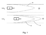
- the drivable area 6 in front of the autonomous road vehicle 2 is determined as an area that belongs to a road travelled 10, which, given sensor and algorithmic uncertainties, is considered safe with a predetermined probability. This allows for efficient monitoring and adaptation of the fusion system 1 by comparing current and retrospective determinations of drivable area 6.
- the direction of travel of the autonomous road vehicle 2 is indicated in figure 1 by the associated arrow.
- Figure 1 illustrates how a determination of drivable area 6 in front of the autonomous road vehicle 2 made at the time to in the upper part of the figure is compared and verified at a subsequent time t 1 .
- the determination made at the time to (dashed) is validated at the subsequent time t 1 , i.e. the drivable area 6 at the time to (dashed in the lower part of figure 1 ) is part of the drivable area 6 at the time t 1 , and thus the reliability of the determination made at the time to can be considered as high.
- the determination of information on surrounding objects 8 comprises classifying surrounding objects 8 with respect to object types, estimating physical property states of surrounding objects 8 including their positions, velocities and accelerations, and assigning the surrounding objects 8 extension descriptions that include sensor uncertainty descriptions, and assigning the surrounding objects 8 a highly automated drive confidence.
- Object types used for the classification may include classes such as car, truck and bus. This provides basis for performing efficient comparisons and evaluations of surrounding objects 8.
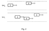
- Figure 2 illustrates an example where an object representation at the time t 1 is not as would have been expected given an estimated state at the time t 0 .
- the object 8 representation may differ in respect of positioning, as illustrated in figure 2 , but also in respect of classification.
- the object 8 was not at the expected position (dashed) at the time t 1 given the estimated state at the time to.
- the directions of travel of the autonomous road vehicle 2 and the object 8 are indicated in figure 2 by the associated arrows.
- a threshold or equivalent can be used for determining how much a previous determination may be allowed to deviate from a current without necessitating distrusting the determination and initiating hand-over of control of the autonomous road vehicle 2 from the autonomous drive system 3 to a driver thereof. While below such a threshold it may suffice to increase an associated sensor uncertainty description, e.g. proportional to the magnitude of the deviation.
- the method further comprises determining if a current determination of a class of a prioritized object differs from a previously determined class of that prioritized object, and if so adapting the fusion system 1 by increasing a sensor uncertainty description associated with that previously determined class.
- the method further comprises determining if a current localization determination of a prioritized object differ from a previous localization determination of that prioritized object more than what a reasonable estimate based on its previous representation would indicate but indicates a localization in a predetermined close vicinity thereto, e.g. using a distance threshold, and if so adapting the fusion system 1 by increasing a sensor uncertainty description associated with that prioritized object. This provides an efficient way of ascertaining the correctness of sensor based localization determinations.
- the method further comprises determining if a current localization determination of a prioritized object differ from a previous localization determination of that prioritized object more than what a reasonable estimate based on its previous representation would indicate and not indicates a localization in a predetermined close vicinity thereto, e.g. using a distance threshold, and if so adapting the fusion system 1 by distrusting the fusion system 1 and initiating hand-over of control of the autonomous road vehicle 2 from the autonomous drive system 3 to a driver thereof.
- This provides an efficient way of determining and handling a fault in the fusion system 1.
- the method comprises determining if a current determination of drivable area 6 indicates a different extension of the drivable area 6 than a previous determination thereof, and if so adapting the fusion system 1 such that future determinations of drivable area 6 are made based on the current determination.
- a current determination of drivable area 6 indicates a different extension of the drivable area 6 than a previous determination thereof, and if so adapting the fusion system 1 such that future determinations of drivable area 6 are made based on the current determination.
- the method comprises determining if a current determination of drivable area 6 indicates a more narrow width of the drivable area 6 than a previous determination thereof, and if so adapting the fusion system 1 such that future determinations of drivable area 6 are made based on a more narrow width of the drivable area 6 than that of the previous determination thereof. This provides an efficient way of improving the drivable area 6 determination in cases where a previous determination seemingly overestimated the width.
- the method comprises determining if a current determination of drivable area 6 indicates a less narrow width of the drivable area 6 than a previous determination thereof, and if so adapting the fusion system 1 such that future determinations of drivable area 6 are made based on a less narrow width of the drivable area 6 than that of the previous determination thereof. This provides an efficient way of improving the drivable area 6 determination in cases where a previous determination seemingly underestimated the width.
- An efficient way of determining and handling a fault in the fusion system 1 comprises determining if a current determination of drivable area 6 indicates that the previously determined drivable area 6 was not drivable at all, and if so adapting the fusion system 1 by distrusting the localization function and initiating hand-over of control of the autonomous road vehicle 2 from the autonomous drive system 3 to a driver thereof.
- Figure 3 illustrates how an object 8 is detected inside an observed area 9 in front of the autonomous road vehicle 2 at a time t 1 while a previous determination at the time to indicated no such object 8, and no determination of that object 8 entering the observed area 9 from the border thereof has been made.
- an efficient way of determining and handling a fault in the fusion system 1 is, according to some further embodiments, provided through that the method comprises determining if a current determination of surrounding objects 8 indicates that a new object 8 has appeared in an observed area 9 where it should have been determined previously, and if so adapting the fusion system 1 by distrusting the fusion system 1 and initiating hand-over of control of the autonomous road vehicle 2 from the autonomous drive system 3 to a driver thereof.
- the direction of travel of the autonomous road vehicle 2 is indicated in figure 3 by the associated arrow.
- the present disclosure also proposes an improved arrangement for monitoring and adapting the performance of a fusion system 1 of an autonomous road vehicle 2.
- the fusion system 1 comprising one or more processing arrangements with associated data storage capabilities arranged to perform the different functions and algorithms that use sensor 5 data to estimate information required for autonomous drive control by the autonomous drive system 3 of the autonomous road vehicle 2.
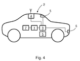
- Figure 4 illustrates schematically an autonomous road vehicle 2 comprising such an arrangement for monitoring and adapting the performance of a fusion system 1 of an autonomous road vehicle 2 equipped with an autonomous drive system 3 comprising a positioning system 4 and multiple sensors 5 for supervising the internal state of the autonomous road vehicle 2 and the surrounding environment.
- a localization function of the fusion system 1 is provided by fusing data from the positioning system 4 and the sensors 5.
- An environmental perception function of the fusion system 1 is provided by fusing data from the sensors 5 supervising the surrounding environment.
- the localization and environmental perception functions of the fusion system 1 are implemented using parallel algorithms based on alternative concepts and using different sets of sensor 5 information.
- the parallel implementations of the localization and environmental perception functions of the fusion system 1 are suitably arranged to enable a use thereof to monitor each other. Such monitoring is useful in order to be able to detect sensor 5 failures and algorithmic inconsistencies.
- the arrangement further comprises the fusion system 1, being arranged to: determine a drivable area 6 in front of the autonomous road vehicle 2 by combining the localization function and high density map 7 data for a current position; determine information on surrounding objects 8, the information determination comprising determining the localization of the surrounding objects 8, classifying the surrounding objects 8, estimating their physical property states, and assigning them extension descriptions and a highly automated drive confidence; condense information on the drivable area 6 and surrounding objects 8 into observed areas 9 and prioritized objects 8, specifying observed areas 9 as the volume around the autonomous road vehicle 2 that has been monitored by the sensors 5 of the environmental perception function with a predetermined degree of certainty, and representing prioritized objects 8 by classes, state estimates, extension descriptions and highly automated drive confidences.
- the fusion system 1 is further arranged to monitor itself retrospectively. This retrospective monitoring is performed by the fusion system 1 being arranged to evaluate its current determinations of drivable area 6, prioritized objects 8 and observed areas 9 against its previous determinations thereof. If a previous determination by the fusion system 1 differ more than a predetermined amount from a current determination, the fusion system 1 is arranged to adapt itself to account for that discrepancy.
- an autonomous road vehicle 2 that comprises an arrangement for monitoring and adapting the performance of a fusion system 1 of an autonomous road vehicle 2, as described above.
- An autonomous road vehicle 2 as described above is able to rely on its fusion system 1 to monitor itself retrospectively, evaluating its current output against its output from an earlier time when it had less information, and adapting the performance of its fusion system 1 based thereupon.
Abstract
Description
- The present disclosure relates to a method for monitoring and adapting the performance of a fusion system of an autonomous road vehicle equipped with an autonomous drive system comprising a positioning system and multiple sensors for supervising the internal state of the autonomous road vehicle and the surrounding environment. The disclosure further relates to an arrangement for monitoring and adapting the performance of a fusion system of an autonomous road vehicle equipped with an autonomous drive system comprising a positioning system and multiple sensors for supervising the internal state of the autonomous road vehicle and the surrounding environment. The disclosure further relates to an autonomous road vehicle that comprises such an arrangement for monitoring and adapting the performance of a fusion system thereof.
- One area of automotive vehicle technology that is evolving rapidly is the area of autonomous or semi-autonomous drive capabilities for road vehicles. This is enabled through the introduction of sensors, for sensing vehicle motion and surroundings, and actuators, for controlling different road vehicle functionalities, such as steering, throttling and braking. Increased on-board data processing capabilities ties together these sensors and actuators such that autonomous or semi-autonomous drive capabilities are enabled.
- When a road vehicle runs in autonomous mode, which means the driver is not required to perform maneuvers, the road vehicle usually is dependent on multiple data sources as inputs to perform the autonomous driving. An autonomous road vehicle requires information about the surrounding environment to drive safely. For instance, a detailed description of the road network inside of which it is operating is required for the autonomous road vehicle to cautiously navigate and plan future trajectories. It must also detect and classify surrounding objects, and estimate their physical properties such as positions, velocities and accelerations. To perform such tasks, autonomous road vehicles are usually provided high density map information and information from multiple sensors measuring both the internal state of the ego vehicle as well as the surrounding environment.
- Compared to safety systems available for non-autonomous road vehicles on the market today, an autonomous self-driving road vehicle must be much more reliable, and have a near zero tolerance for serious errors. To accomplish this level of accuracy and reliability, a high degree of sensor redundancy is necessary. This is commonly accomplished through fusing data from multiple sources to provide environmental perception and localization functions where the different functions and algorithms that use sensor data to estimate the required information for enabling reliable autonomous travel are collectively referred to as a fusion system.
- Although such fusion systems are known to be used for enabling autonomous travel of road vehicles there is still room for improving the performance of such fusion systems.
- Embodiments herein aim to provide an improved method for monitoring and adapting the performance, and thus also safety, of a fusion system of an autonomous road vehicle equipped with an autonomous drive system comprising a positioning system and multiple sensors for supervising the internal state of the autonomous road vehicle and the surrounding environment.
- This is provided through a method where a localization function of the fusion system is provided by fusing data from the positioning system and the sensors; an environmental perception function of the fusion system is provided by fusing data from the sensors supervising the surrounding environment; and where the localization and environmental perception functions of the fusion system are implemented using parallel algorithms based on alternative concepts and using different sets of sensor information, and where the method further comprises: determining a drivable area in front of the autonomous road vehicle by combining the localization function and high density map data for a current position; determining information on surrounding objects, the information determination comprising determining the localization of the surrounding objects, classifying the surrounding objects, estimating their physical property states, and assigning them extension descriptions and a highly automated drive confidence; condensing information on the drivable area and surrounding objects into observed areas and prioritized objects, specifying observed areas as the volume around the autonomous road vehicle that has been monitored by the sensors of the environmental perception function with a predetermined degree of certainty, and representing prioritized objects by classes, state estimates, extension descriptions and highly automated drive confidences; and having the fusion system monitor itself retrospectively by evaluating its current determinations of drivable area, prioritized objects and observed areas against its previous determinations thereof, and if a previous determination differ more than a predetermined amount from a current determination, adapting the fusion system to account for that discrepancy.
- According to a second aspect is provided that the drivable area in front of the autonomous road vehicle is determined as an area that belongs to a road travelled, which, given sensor and algorithmic uncertainties, is considered safe with a predetermined probability.
- The provision of determining the drivable area as an area that belongs to a road travelled which is considered safe with a predetermined probability as above allows for efficient monitoring and adaptation of the fusion system by comparing current and retrospective determinations of drivable area.
- According to a third aspect is provided that the determination of information on surrounding objects comprises classifying surrounding objects with respect to object types, estimating physical property states of surrounding objects including their positions, velocities and accelerations, and assigning the surrounding objects extension descriptions that include sensor uncertainty descriptions.
- The provision of classifying surrounding objects, estimating their physical property states and assigning them extension descriptions as above provides basis for performing efficient comparisons and evaluations of surrounding objects.
- According to a fourth aspect is provided that it further comprises determining if a current determination of a class of a prioritized object differs from a previously determined class of that prioritized object, and if so adapting the fusion system by increasing a sensor uncertainty description associated with that previously determined class.
- The provision of comparing a current and a retrospective determination of a class of a prioritized object as above provide an efficient way of ascertaining the correctness of sensor determinations.
- According to a fifth aspect is provided that it further comprises determining if a current localization determination of a prioritized object differ from a previous localization determination of that prioritized object more than what a reasonable estimate based on its previous representation would indicate but indicates a localization in a predetermined close vicinity thereto, and if so adapting the fusion system by increasing a sensor uncertainty description associated with that prioritized object.
- The provision of adapting the fusion system as above after comparing a current and a retrospective localization determination of a prioritized object as above provides an efficient way of ascertaining the correctness of sensor based localization determinations.
- According to a sixth aspect is provided that it further comprises determining if a current localization determination of a prioritized object differ from a previous localization determination of that prioritized object more than what a reasonable estimate based on its previous representation would indicate and not indicates a localization in a predetermined close vicinity thereto, and if so adapting the fusion system by distrusting the fusion system and initiating hand-over of control of the autonomous road vehicle from the autonomous drive system to a driver thereof.
- The provision of distrusting the fusion system as above after comparing a current and a retrospective localization determination of a prioritized object as above provides an efficient way of determining and handling a fault in the fusion system.
- According to a seventh aspect is provided that it comprises determining if a current determination of drivable area indicates a different extension of the drivable area than a previous determination thereof, and if so adapting the fusion system such that future determinations of drivable area are made based on the current determination.
- The provision of comparing a current and a retrospective determination of drivable area to see if the current determination indicates a different extension of the drivable area than the previous as above provide an efficient way of improving the drivable area determination.
- According to an eight aspect is provided that it comprises determining if a current determination of drivable area indicates a more narrow width of the drivable area than a previous determination thereof, and if so adapting the fusion system such that future determinations of drivable area are made based on a more narrow width of the drivable area than that of the previous determination thereof.
- The provision of comparing a current and a retrospective determination of drivable area to see if the current determination indicates a more narrow width than the previous as above provide an efficient way of improving the drivable area determination in cases where a previous determination seemingly overestimated the width.
- According to a ninth aspect is provided that it comprises determining if a current determination of drivable area indicates a less narrow width of the drivable area than a previous determination thereof, and if so adapting the fusion system such that future determinations of drivable area are made based on a less narrow width of the drivable area than that of the previous determination thereof.
- The provision of comparing a current and a retrospective determination of drivable area to see if the current determination indicates a less narrow width than the previous as above provide an efficient way of improving the drivable area determination in cases where a previous determination seemingly underestimated the width.
- According to a tenth aspect is provided that it comprises determining if a current determination of drivable area indicates that the previously determined drivable area was not drivable at all, and if so adapting the fusion system by distrusting the localization function and initiating hand-over of control of the autonomous road vehicle from the autonomous drive system to a driver thereof.
- The provision of distrusting the localization function as above after determining that a retrospective determination of drivable area was flawed as above provides an efficient way of determining and handling a fault in the fusion system.
- According to an eleventh aspect is provided that it comprises determining if a current determination of surrounding objects indicates that a new object has appeared in an area where it should have been determined previously, and if so adapting the fusion system by distrusting the fusion system and initiating hand-over of control of the autonomous road vehicle from the autonomous drive system to a driver thereof.
- The provision of distrusting the fusion system as above after determining that a retrospective determination of surrounding objects was flawed as above provides an efficient way of determining and handling a fault in the fusion system.
- According to a twelfth aspect embodiments herein also aim to provide an improved arrangement for monitoring and adapting the performance of a fusion system of an autonomous road vehicle equipped with an autonomous drive system comprising a positioning system and multiple sensors for supervising the internal state of the autonomous road vehicle and the surrounding environment.
- This is provided through an arrangement where: a localization function of the fusion system is provided by fusing data from the positioning system and the sensors; an environmental perception function of the fusion system is provided by fusing data from the sensors supervising the surrounding environment; and where the localization and environmental perception functions of the fusion system are implemented using parallel algorithms based on alternative concepts and using different sets of sensor information, and the arrangement further comprising the fusion system being arranged to: determine a drivable area in front of the autonomous road vehicle by combining the localization function and high density map data for a current position; determine information on surrounding objects, the information determination comprising determining the localization of the surrounding objects, classifying the surrounding objects, estimating their physical property states, and assigning them extension descriptions and a highly automated drive confidence; condense information on the drivable area and surrounding objects into observed areas and prioritized objects, specifying observed areas as the volume around the autonomous road vehicle that has been monitored by the sensors of the environmental perception function with a predetermined degree of certainty, and representing prioritized objects by classes, state estimates, extension descriptions and highly automated drive confidences; and the fusion system further being arranged to monitor itself retrospectively by evaluating its current determinations of drivable area, prioritized objects and observed areas against its previous determinations thereof, and if a previous determination differ more than a predetermined amount from a current determination, adapt the fusion system to account for that discrepancy.
- According to a final aspect is provided an autonomous road vehicle that comprises an arrangement for monitoring and adapting the performance of a fusion system of an autonomous road vehicle as above.
- An autonomous road vehicle as above is able to rely on its fusion system to monitor itself retrospectively, evaluating its current output against its output from an earlier time when it had less information, and adapting the performance of its fusion system based thereupon.
- In the following, embodiments herein will be described in greater detail by way of example only with reference to attached drawings, in which
-
Fig. 1 is a schematic illustration of a retrospective and a current determination of drivable area for monitoring and adapting the performance of a fusion system according to embodiments herein. -
Fig. 2 is a schematic illustration of a retrospective and a current object representation for monitoring and adapting the performance of a fusion system according to embodiments herein. -
Fig. 3 is a schematic illustration of a retrospective and a current determination of observed area for monitoring and adapting the performance of a fusion system according to embodiments herein. -
Fig. 4 is a schematic illustration of an autonomous road vehicle comprising an arrangement for monitoring and adapting the performance of a fusion system according to embodiments herein. - Still other objects and features of embodiments herein will become apparent from the following detailed description considered in conjunction with the accompanying drawings. It is to be understood, however, that the drawings are designed solely for purposes of illustration and not as a definition of the limits hereof, for which reference should be made to the appended claims. It should be further understood that the drawings are not necessarily drawn to scale and that, unless otherwise indicated, they are merely intended to conceptually illustrate the structures and procedures described herein.
- The present disclosure proposes an improved method for monitoring and adapting the performance, and thus also safety, of a
fusion system 1 of anautonomous road vehicle 2. - This is provided through a method for monitoring and adapting the performance of a
fusion system 1 of anautonomous road vehicle 2 equipped with anautonomous drive system 3 comprising apositioning system 4, such as a satellite basedpositioning system 4, e.g. GPS, andmultiple sensors 5 for supervising the internal state of theautonomous road vehicle 2 and the surrounding environment. Examples ofsensors 5 for supervising the surrounding environment include radar, lidar and camera basedsensors 5. - A
fusion system 1 of anautonomous road vehicle 2, as used herein, designates different functions and algorithms that use sensor data to estimate information required for autonomous drive control of anautonomous road vehicle 2. - A localization function of the
fusion system 1 is provided by fusing data from thepositioning system 4 and thesensors 5. An environmental perception function of thefusion system 1 is provided by fusing data from thesensors 5 supervising the surrounding environment. The localization and environmental perception functions of thefusion system 1 are implemented using parallel algorithms based on alternative concepts and using different sets of sensor information. The parallel implementations enable self-monitoring, as the parallel algorithms can be used to monitor each other to detect sensor failures and algorithmic inconsistencies. - The method further comprises determining a
drivable area 6 in front of theautonomous road vehicle 2 by combining the localization function andhigh density map 7 data for a current position. - The method still further comprises determining information on surrounding
objects 8, where the information determination comprises determining the localization of the surroundingobjects 8, classifying the surroundingobjects 8, estimating their physical property states, and assigning them extension descriptions and a highly automated drive confidence. - Further, a self-driving road vehicle must be able to perform automatic lane changes, adapt to a current traffic flow and, in an emergency, brake urgently. Thus it requires accurate information about the surrounding environment, which is provided by fusing the different sensor observations.
- Thus the method further comprises condensing information on the
drivable area 6 and surroundingobjects 8 into observedareas 9 and prioritizedobjects 8, specifying observedareas 9 as the volume around theautonomous road vehicle 2 that has been monitored by thesensors 5 of the environmental perception function with a predetermined degree of certainty, and representing prioritizedobjects 8 by classes, state estimates, extension descriptions and highly automated drive confidences. - As the
fusion system 1 gathers more and more information from sensor observations, it becomes possible for it to evaluate its output from an earlier time when it had less information. Thus the method further comprises having thefusion system 1 monitor itself retrospectively. - According to the method the
fusion system 1 monitors itself retrospectively by evaluating its current determinations ofdrivable area 6, prioritizedobjects 8 and observedareas 9 against its previous determinations thereof, and if a previous determination differ more than a predetermined amount from a current determination, adapting thefusion system 1 to account for that discrepancy. In this way thefusion system 1 will continuously improve the reliability of its determinations. - A previous determination, as used herein, can e.g. be at determination made a predetermined time before a current determination, e.g. such that the previous determination was made at a time t=t0 and a current determination at a time t=t1, where the time period between t0 and t1 e.g. may be a fragment of a second. The previous determination may be retained in a memory of the
fusion system 1, in order to enable comparison thereof with the current determination. - According to some embodiments herein, as illustrated in
figure 1 , it is provided that thedrivable area 6 in front of theautonomous road vehicle 2 is determined as an area that belongs to a road travelled 10, which, given sensor and algorithmic uncertainties, is considered safe with a predetermined probability. This allows for efficient monitoring and adaptation of thefusion system 1 by comparing current and retrospective determinations ofdrivable area 6. The direction of travel of theautonomous road vehicle 2 is indicated infigure 1 by the associated arrow. -
Figure 1 illustrates how a determination ofdrivable area 6 in front of theautonomous road vehicle 2 made at the time to in the upper part of the figure is compared and verified at a subsequent time t1. As illustrated in the lower part offigure 1 the determination made at the time to (dashed) is validated at the subsequent time t1, i.e. thedrivable area 6 at the time to (dashed in the lower part offigure 1 ) is part of thedrivable area 6 at the time t1, and thus the reliability of the determination made at the time to can be considered as high. - In further embodiments of the method it is provided that the determination of information on surrounding
objects 8 comprises classifying surroundingobjects 8 with respect to object types, estimating physical property states of surroundingobjects 8 including their positions, velocities and accelerations, and assigning the surroundingobjects 8 extension descriptions that include sensor uncertainty descriptions, and assigning the surrounding objects 8 a highly automated drive confidence. Object types used for the classification may include classes such as car, truck and bus. This provides basis for performing efficient comparisons and evaluations of surroundingobjects 8. -
Figure 2 illustrates an example where an object representation at the time t1 is not as would have been expected given an estimated state at the time t0. Theobject 8 representation may differ in respect of positioning, as illustrated infigure 2 , but also in respect of classification. In the lower part offigure 2 , depicting the situation at the time t1, theobject 8 was not at the expected position (dashed) at the time t1 given the estimated state at the time to. The directions of travel of theautonomous road vehicle 2 and theobject 8 are indicated infigure 2 by the associated arrows. A threshold or equivalent can be used for determining how much a previous determination may be allowed to deviate from a current without necessitating distrusting the determination and initiating hand-over of control of theautonomous road vehicle 2 from theautonomous drive system 3 to a driver thereof. While below such a threshold it may suffice to increase an associated sensor uncertainty description, e.g. proportional to the magnitude of the deviation. - According to still some further embodiments the method further comprises determining if a current determination of a class of a prioritized object differs from a previously determined class of that prioritized object, and if so adapting the
fusion system 1 by increasing a sensor uncertainty description associated with that previously determined class. Hereby is provided an efficient way of ascertaining the correctness of sensor determinations. - In yet some embodiments the method further comprises determining if a current localization determination of a prioritized object differ from a previous localization determination of that prioritized object more than what a reasonable estimate based on its previous representation would indicate but indicates a localization in a predetermined close vicinity thereto, e.g. using a distance threshold, and if so adapting the
fusion system 1 by increasing a sensor uncertainty description associated with that prioritized object. This provides an efficient way of ascertaining the correctness of sensor based localization determinations. - According to still further embodiments the method further comprises determining if a current localization determination of a prioritized object differ from a previous localization determination of that prioritized object more than what a reasonable estimate based on its previous representation would indicate and not indicates a localization in a predetermined close vicinity thereto, e.g. using a distance threshold, and if so adapting the
fusion system 1 by distrusting thefusion system 1 and initiating hand-over of control of theautonomous road vehicle 2 from theautonomous drive system 3 to a driver thereof. This provides an efficient way of determining and handling a fault in thefusion system 1. - In yet some embodiments the method comprises determining if a current determination of
drivable area 6 indicates a different extension of thedrivable area 6 than a previous determination thereof, and if so adapting thefusion system 1 such that future determinations ofdrivable area 6 are made based on the current determination. Hereby is provided an efficient way of improving thedrivable area 6 determination. - The method, according to some further embodiments, comprises determining if a current determination of
drivable area 6 indicates a more narrow width of thedrivable area 6 than a previous determination thereof, and if so adapting thefusion system 1 such that future determinations ofdrivable area 6 are made based on a more narrow width of thedrivable area 6 than that of the previous determination thereof. This provides an efficient way of improving thedrivable area 6 determination in cases where a previous determination seemingly overestimated the width. - Conversely, according to still some further embodiments the method comprises determining if a current determination of
drivable area 6 indicates a less narrow width of thedrivable area 6 than a previous determination thereof, and if so adapting thefusion system 1 such that future determinations ofdrivable area 6 are made based on a less narrow width of thedrivable area 6 than that of the previous determination thereof. This provides an efficient way of improving thedrivable area 6 determination in cases where a previous determination seemingly underestimated the width. - An efficient way of determining and handling a fault in the
fusion system 1 is, according to some further embodiments, provided through that the method comprises determining if a current determination ofdrivable area 6 indicates that the previously determineddrivable area 6 was not drivable at all, and if so adapting thefusion system 1 by distrusting the localization function and initiating hand-over of control of theautonomous road vehicle 2 from theautonomous drive system 3 to a driver thereof. -
Figure 3 illustrates how anobject 8 is detected inside an observedarea 9 in front of theautonomous road vehicle 2 at a time t1 while a previous determination at the time to indicated nosuch object 8, and no determination of thatobject 8 entering the observedarea 9 from the border thereof has been made. In such a case, an efficient way of determining and handling a fault in thefusion system 1 is, according to some further embodiments, provided through that the method comprises determining if a current determination of surroundingobjects 8 indicates that anew object 8 has appeared in an observedarea 9 where it should have been determined previously, and if so adapting thefusion system 1 by distrusting thefusion system 1 and initiating hand-over of control of theautonomous road vehicle 2 from theautonomous drive system 3 to a driver thereof. The direction of travel of theautonomous road vehicle 2 is indicated infigure 3 by the associated arrow. - Still further, the present disclosure also proposes an improved arrangement for monitoring and adapting the performance of a
fusion system 1 of anautonomous road vehicle 2. Thefusion system 1 comprising one or more processing arrangements with associated data storage capabilities arranged to perform the different functions and algorithms that usesensor 5 data to estimate information required for autonomous drive control by theautonomous drive system 3 of theautonomous road vehicle 2. -
Figure 4 illustrates schematically anautonomous road vehicle 2 comprising such an arrangement for monitoring and adapting the performance of afusion system 1 of anautonomous road vehicle 2 equipped with anautonomous drive system 3 comprising apositioning system 4 andmultiple sensors 5 for supervising the internal state of theautonomous road vehicle 2 and the surrounding environment. - In the arrangement a localization function of the
fusion system 1 is provided by fusing data from thepositioning system 4 and thesensors 5. An environmental perception function of thefusion system 1 is provided by fusing data from thesensors 5 supervising the surrounding environment. - The localization and environmental perception functions of the
fusion system 1 are implemented using parallel algorithms based on alternative concepts and using different sets ofsensor 5 information. The parallel implementations of the localization and environmental perception functions of thefusion system 1 are suitably arranged to enable a use thereof to monitor each other. Such monitoring is useful in order to be able to detectsensor 5 failures and algorithmic inconsistencies. - The arrangement further comprises the
fusion system 1, being arranged to: determine adrivable area 6 in front of theautonomous road vehicle 2 by combining the localization function andhigh density map 7 data for a current position; determine information on surroundingobjects 8, the information determination comprising determining the localization of the surroundingobjects 8, classifying the surroundingobjects 8, estimating their physical property states, and assigning them extension descriptions and a highly automated drive confidence; condense information on thedrivable area 6 and surroundingobjects 8 into observedareas 9 and prioritizedobjects 8, specifying observedareas 9 as the volume around theautonomous road vehicle 2 that has been monitored by thesensors 5 of the environmental perception function with a predetermined degree of certainty, and representing prioritizedobjects 8 by classes, state estimates, extension descriptions and highly automated drive confidences. - In order to improve the reliability of the
fusion system 1 and decrease the risk of serious errors thefusion system 1 is further arranged to monitor itself retrospectively. This retrospective monitoring is performed by thefusion system 1 being arranged to evaluate its current determinations ofdrivable area 6, prioritizedobjects 8 and observedareas 9 against its previous determinations thereof. If a previous determination by thefusion system 1 differ more than a predetermined amount from a current determination, thefusion system 1 is arranged to adapt itself to account for that discrepancy. - Finally, the present disclosure also proposes an
autonomous road vehicle 2 that comprises an arrangement for monitoring and adapting the performance of afusion system 1 of anautonomous road vehicle 2, as described above. - Further details of the
autonomous road vehicle 2, such as propulsion system, steering system, brake system etc, are intentionally left out fromfigure 4 , in order to no unnecessarily obscure details promoting the understanding of the arrangement according to the present disclosure. However, the person skilled in the art will readily be able to envisage such further details. - An
autonomous road vehicle 2 as described above is able to rely on itsfusion system 1 to monitor itself retrospectively, evaluating its current output against its output from an earlier time when it had less information, and adapting the performance of itsfusion system 1 based thereupon. - The above-described embodiments may be varied within the scope of the following claims.
- Thus, while there have been shown and described and pointed out fundamental novel features of the embodiments herein, it will be understood that various omissions and substitutions and changes in the form and details of the devices illustrated, and in their operation, may be made by those skilled in the art. For example, it is expressly intended that all combinations of those elements and/or method steps which perform substantially the same function in substantially the same way to achieve the same results are equivalent. Moreover, it should be recognized that structures and/or elements and/or method steps shown and/or described in connection with any disclosed form or embodiment herein may be incorporated in any other disclosed or described or suggested form or embodiment as a general matter of design choice.
Claims (13)
- A method for monitoring and adapting the performance of a fusion system (1) of an autonomous road vehicle (2) equipped with an autonomous drive system (3) comprising a positioning system (4) and multiple sensors (5) for supervising the internal state of the autonomous road vehicle (2) and the surrounding environment, characterized in that:a localization function of the fusion system (1) is provided by fusing data from the positioning system (4) and the sensors (5);an environmental perception function of the fusion system (1) is provided by fusing data from the sensors (5) supervising the surrounding environment; andwhere the localization and environmental perception functions of the fusion system (1) are implemented using parallel algorithms based on alternative concepts and using different sets of sensor information,the method further comprises:determining a drivable area (6) in front of the autonomous road vehicle (2) by combining the localization function and high density map (7) data for a current position;determining information on surrounding objects (8), the information determination comprising determining the localization of the surrounding objects (8), classifying the surrounding objects (8), estimating their physical property states, and assigning them extension descriptions and a highly automated drive confidence;condensing information on the drivable area (6) and surrounding objects (8) into observed areas (9) and prioritized objects (8), specifying observed areas (9) as the volume around the autonomous road vehicle (2) that has been monitored by the sensors (5) of the environmental perception function with a predetermined degree of certainty, and representing prioritized objects (8) by classes, state estimates, extension descriptions and highly automated drive confidences; andhaving the fusion system (1) monitor itself retrospectively by evaluating its current determinations of drivable area (6), prioritized objects (8) and observed areas (9) against its previous determinations thereof, and if a previous determination differ more than a predetermined amount from a current determination, adapting the fusion system (1) to account for that discrepancy.
- The method according to claim 1, characterized in that the drivable area (6) in front of the autonomous road vehicle (2) is determined as an area that belongs to a road travelled (10), which, given sensor and algorithmic uncertainties, is considered safe with a predetermined probability.
- The method according to any one of claims 1 to 2, characterized in that the determination of information on surrounding objects (8) comprises classifying surrounding objects (8) with respect to object types, estimating physical property states of surrounding objects (8) including their positions, velocities and accelerations, and assigning the surrounding objects (8) extension descriptions that include sensor uncertainty descriptions.
- The method according to claim 3, characterized in that it further comprises determining if a current determination of a class of a prioritized object differs from a previously determined class of that prioritized object, and if so adapting the fusion system (1) by increasing a sensor uncertainty description associated with that previously determined class.
- The method according to claims 3, characterized in that it further comprises determining if a current localization determination of a prioritized object differ from a previous localization determination of that prioritized object more than what a reasonable estimate based on its previous representation would indicate but indicates a localization in a predetermined close vicinity thereto, and if so adapting the fusion system (1) by increasing a sensor uncertainty description associated with that prioritized object.
- The method according to any one of claims 1 to 3, characterized in that it further comprises determining if a current localization determination of a prioritized object differ from a previous localization determination of that prioritized object more than what a reasonable estimate based on its previous representation would indicate and not indicates a localization in a predetermined close vicinity thereto, and if so adapting the fusion system (1) by distrusting the fusion system (1) and initiating hand-over of control of the autonomous road vehicle (2) from the autonomous drive system (3) to a driver thereof.
- The method according to any one of claims 1 to 6, characterized in that it comprises determining if a current determination of drivable area (6) indicates a different extension of the drivable area (6) than a previous determination thereof, and if so adapting the fusion system (1) such that future determinations of drivable area (6) are made based on the current determination.
- The method according to claim 7, characterized in that it comprises determining if a current determination of drivable area (6) indicates a more narrow width of the drivable area (6) than a previous determination thereof, and if so adapting the fusion system (1) such that future determinations of drivable area (6) are made based on a more narrow width of the drivable area (6) than that of the previous determination thereof.
- The method according to claim 7, characterized in that it comprises determining if a current determination of drivable area (6) indicates a less narrow width of the drivable area (6) than a previous determination thereof, and if so adapting the fusion system (1) such that future determinations of drivable area (6) are made based on a less narrow width of the drivable area (6) than that of the previous determination thereof.
- The method according to any one of claims 1 to 9, characterized in that it comprises determining if a current determination of drivable area (6) indicates that the previously determined drivable area (6) was not drivable at all, and if so adapting the fusion system (1) by distrusting the localization function and initiating hand-over of control of the autonomous road vehicle (2) from the autonomous drive system (3) to a driver thereof.
- The method according to any one of claims 1 to 10, characterized in that it comprises determining if a current determination of surrounding objects (8) indicates that a new object has appeared in an area where it should have been determined previously, and if so adapting the fusion system (1) by distrusting the fusion system (1) and initiating hand-over of control of the autonomous road vehicle (2) from the autonomous drive system (3) to a driver thereof.
- An arrangement for monitoring and adapting the performance of a fusion system (1) of an autonomous road vehicle (2) equipped with an autonomous drive system (3) comprising a positioning system (4) and multiple sensors (5) for supervising the internal state of the autonomous road vehicle (2) and the surrounding environment, characterized in that:a localization function of the fusion system (1) is provided by fusing data from the positioning system (4) and the sensors (5);an environmental perception function of the fusion system (1) is provided by fusing data from the sensors (5) supervising the surrounding environment; andwhere the localization and environmental perception functions of the fusion system (1) are implemented using parallel algorithms based on alternative concepts and using different sets of sensor information,the arrangement further comprising the fusion system (1) being arranged to:determine a drivable area (6) in front of the autonomous road vehicle (2) by combining the localization function and high density map (7) data for a current position;determine information on surrounding objects (8), the information determination comprising determining the localization of the surrounding objects (8), classifying the surrounding objects (8), estimating their physical property states, and assigning them extension descriptions and a highly automated drive confidence;condense information on the drivable area (6) and surrounding objects (8) into observed areas (9) and prioritized objects (8), specifying observed areas (9) as the volume around the autonomous road vehicle (2) that has been monitored by the sensors (5) of the environmental perception function with a predetermined degree of certainty, and representing prioritized objects (8) by classes, state estimates, extension descriptions and highly automated drive confidences; andthe fusion system (1) further being arranged to monitor itself retrospectively by evaluating its current determinations of drivable area (6), prioritized objects (8) and observed areas (9) against its previous determinations thereof, and if a previous determination differ more than a predetermined amount from a current determination, adapt the fusion system (1) to account for that discrepancy.
- An autonomous road vehicle (2), characterized in that it comprises an arrangement for monitoring and adapting the performance of a fusion system (1) of an autonomous road vehicle (2) according to claim 12.
Priority Applications (3)
| Application Number | Priority Date | Filing Date | Title |
|---|---|---|---|
| EP16165223.5A EP3232285B1 (en) | 2016-04-14 | 2016-04-14 | Method and arrangement for monitoring and adapting the performance of a fusion system of an autonomous vehicle |
| US15/467,297 US10532740B2 (en) | 2016-04-14 | 2017-03-23 | Method and arrangement for monitoring and adapting the performance of a fusion system of an autonomous vehicle |
| CN201710219248.0A CN107300916B (en) | 2016-04-14 | 2017-04-06 | Method and apparatus for monitoring and adjusting performance of a fusion system of autonomous vehicles |
Applications Claiming Priority (1)
| Application Number | Priority Date | Filing Date | Title |
|---|---|---|---|
| EP16165223.5A EP3232285B1 (en) | 2016-04-14 | 2016-04-14 | Method and arrangement for monitoring and adapting the performance of a fusion system of an autonomous vehicle |
Publications (2)
| Publication Number | Publication Date |
|---|---|
| EP3232285A1 true EP3232285A1 (en) | 2017-10-18 |
| EP3232285B1 EP3232285B1 (en) | 2019-12-18 |
Family
ID=56014782
Family Applications (1)
| Application Number | Title | Priority Date | Filing Date |
|---|---|---|---|
| EP16165223.5A Active EP3232285B1 (en) | 2016-04-14 | 2016-04-14 | Method and arrangement for monitoring and adapting the performance of a fusion system of an autonomous vehicle |
Country Status (3)
| Country | Link |
|---|---|
| US (1) | US10532740B2 (en) |
| EP (1) | EP3232285B1 (en) |
| CN (1) | CN107300916B (en) |
Families Citing this family (14)
| Publication number | Priority date | Publication date | Assignee | Title |
|---|---|---|---|---|
| US9630619B1 (en) | 2015-11-04 | 2017-04-25 | Zoox, Inc. | Robotic vehicle active safety systems and methods |
| WO2017079341A2 (en) | 2015-11-04 | 2017-05-11 | Zoox, Inc. | Automated extraction of semantic information to enhance incremental mapping modifications for robotic vehicles |
| US9606539B1 (en) | 2015-11-04 | 2017-03-28 | Zoox, Inc. | Autonomous vehicle fleet service and system |
| US11283877B2 (en) | 2015-11-04 | 2022-03-22 | Zoox, Inc. | Software application and logic to modify configuration of an autonomous vehicle |
| US10401852B2 (en) | 2015-11-04 | 2019-09-03 | Zoox, Inc. | Teleoperation system and method for trajectory modification of autonomous vehicles |
| US10334050B2 (en) * | 2015-11-04 | 2019-06-25 | Zoox, Inc. | Software application and logic to modify configuration of an autonomous vehicle |
| US9632502B1 (en) | 2015-11-04 | 2017-04-25 | Zoox, Inc. | Machine-learning systems and techniques to optimize teleoperation and/or planner decisions |
| US9754490B2 (en) | 2015-11-04 | 2017-09-05 | Zoox, Inc. | Software application to request and control an autonomous vehicle service |
| US10409286B2 (en) * | 2017-07-21 | 2019-09-10 | Ford Global Technologies, Llc | Highway detection systems and methods |
| KR102371616B1 (en) * | 2017-11-07 | 2022-03-07 | 현대자동차주식회사 | Apparatus and method for associating sensor data of vehicle |
| US11561547B2 (en) * | 2019-02-20 | 2023-01-24 | Gm Cruise Holdings Llc | Autonomous vehicle routing based upon spatiotemporal factors |
| CN111797701A (en) * | 2020-06-10 | 2020-10-20 | 东莞正扬电子机械有限公司 | Road obstacle sensing method and system for vehicle multi-sensor fusion system |
| US20220379911A1 (en) * | 2021-05-26 | 2022-12-01 | Argo AI, LLC | Using relevance of objects to assess performance of an autonomous vehicle perception system |
| EP4134623A1 (en) | 2021-08-11 | 2023-02-15 | Hitachi Astemo, Ltd. | Drive device, vehicle, and method for automated driving and/or assisted driving |
Citations (4)
| Publication number | Priority date | Publication date | Assignee | Title |
|---|---|---|---|---|
| US6718259B1 (en) * | 2002-10-02 | 2004-04-06 | Hrl Laboratories, Llc | Adaptive Kalman filter method for accurate estimation of forward path geometry of an automobile |
| US20050021201A1 (en) * | 2001-07-17 | 2005-01-27 | Albrecht Klotz | Method and device for data exchange and processing |
| EP2865575A1 (en) * | 2013-10-22 | 2015-04-29 | Honda Research Institute Europe GmbH | Confidence estimation for predictive driver assistance systems based on plausibility rules |
| US9274525B1 (en) * | 2012-09-28 | 2016-03-01 | Google Inc. | Detecting sensor degradation by actively controlling an autonomous vehicle |
Family Cites Families (6)
| Publication number | Priority date | Publication date | Assignee | Title |
|---|---|---|---|---|
| US8458715B1 (en) * | 2007-02-23 | 2013-06-04 | Hrl Laboratories, Llc | System for allocating resources to optimize transition from a current state to a desired state |
| EP2615598B1 (en) * | 2012-01-11 | 2017-12-06 | Honda Research Institute Europe GmbH | Vehicle with computing means for monitoring and predicting traffic participant objects |
| CN102785579A (en) * | 2012-08-21 | 2012-11-21 | 江苏云意电气股份有限公司 | Self-diagnosis car adjuster fused with data |
| CN103118439B (en) * | 2013-01-18 | 2016-03-23 | 中国科学院上海微系统与信息技术研究所 | based on the data fusion method of sensor network node universal middleware |
| US9268938B1 (en) * | 2015-05-22 | 2016-02-23 | Power Fingerprinting Inc. | Systems, methods, and apparatuses for intrusion detection and analytics using power characteristics such as side-channel information collection |
| US20170291544A1 (en) * | 2016-04-12 | 2017-10-12 | Toyota Motor Engineering & Manufacturing North America, Inc. | Adaptive alert system for autonomous vehicle |
-
2016
- 2016-04-14 EP EP16165223.5A patent/EP3232285B1/en active Active
-
2017
- 2017-03-23 US US15/467,297 patent/US10532740B2/en active Active
- 2017-04-06 CN CN201710219248.0A patent/CN107300916B/en active Active
Patent Citations (4)
| Publication number | Priority date | Publication date | Assignee | Title |
|---|---|---|---|---|
| US20050021201A1 (en) * | 2001-07-17 | 2005-01-27 | Albrecht Klotz | Method and device for data exchange and processing |
| US6718259B1 (en) * | 2002-10-02 | 2004-04-06 | Hrl Laboratories, Llc | Adaptive Kalman filter method for accurate estimation of forward path geometry of an automobile |
| US9274525B1 (en) * | 2012-09-28 | 2016-03-01 | Google Inc. | Detecting sensor degradation by actively controlling an autonomous vehicle |
| EP2865575A1 (en) * | 2013-10-22 | 2015-04-29 | Honda Research Institute Europe GmbH | Confidence estimation for predictive driver assistance systems based on plausibility rules |
Also Published As
| Publication number | Publication date |
|---|---|
| US10532740B2 (en) | 2020-01-14 |
| CN107300916A (en) | 2017-10-27 |
| US20170297571A1 (en) | 2017-10-19 |
| EP3232285B1 (en) | 2019-12-18 |
| CN107300916B (en) | 2021-03-12 |
Similar Documents
| Publication | Publication Date | Title |
|---|---|---|
| EP3232285B1 (en) | Method and arrangement for monitoring and adapting the performance of a fusion system of an autonomous vehicle | |
| US11079754B2 (en) | Multi-stage operation of autonomous vehicles | |
| US10152056B2 (en) | Method for selecting an optimized trajectory | |
| CN109937389B (en) | Operation safety system for automatic vehicle | |
| CN108137054B (en) | Replacement of sensor measurement data | |
| US10369993B2 (en) | Method and device for monitoring a setpoint trajectory to be traveled by a vehicle for being collision free | |
| CN111547053A (en) | Automatic driving control method and system based on vehicle-road cooperation | |
| US11608059B2 (en) | Method and apparatus for method for real time lateral control and steering actuation assessment | |
| US10095238B2 (en) | Autonomous vehicle object detection | |
| CN108960083B (en) | Automatic driving target classification method and system based on multi-sensor information fusion | |
| US20220289198A1 (en) | Automated emergency braking system | |
| CN110562269A (en) | Method for processing fault of intelligent driving vehicle, vehicle-mounted equipment and storage medium | |
| CN114274972A (en) | Scene recognition in an autonomous driving environment | |
| US11531349B2 (en) | Corner case detection and collection for a path planning system | |
| US20220254204A1 (en) | Checkpoint-Based Tracing for Monitoring a Robotic System | |
| US20230135159A1 (en) | Method for evaluating route sections | |
| CN114475634A (en) | Method for controlling a vehicle along a route section by means of a controller and storage medium | |
| US20230266759A1 (en) | Sensor layout techniques | |
| US20240013312A1 (en) | Information processing method and information processing system | |
| US20240067216A1 (en) | Verification of vehicle prediction function | |
| Maranga et al. | Short paper: Inter-vehicular distance improvement using position information in a collaborative adaptive cruise control system |
Legal Events
| Date | Code | Title | Description |
|---|---|---|---|
| PUAI | Public reference made under article 153(3) epc to a published international application that has entered the european phase |
Free format text: ORIGINAL CODE: 0009012 |
|
| STAA | Information on the status of an ep patent application or granted ep patent |
Free format text: STATUS: THE APPLICATION HAS BEEN PUBLISHED |
|
| AK | Designated contracting states |
Kind code of ref document: A1 Designated state(s): AL AT BE BG CH CY CZ DE DK EE ES FI FR GB GR HR HU IE IS IT LI LT LU LV MC MK MT NL NO PL PT RO RS SE SI SK SM TR |
|
| AX | Request for extension of the european patent |
Extension state: BA ME |
|
| STAA | Information on the status of an ep patent application or granted ep patent |
Free format text: STATUS: REQUEST FOR EXAMINATION WAS MADE |
|
| 17P | Request for examination filed |
Effective date: 20180418 |
|
| RBV | Designated contracting states (corrected) |
Designated state(s): AL AT BE BG CH CY CZ DE DK EE ES FI FR GB GR HR HU IE IS IT LI LT LU LV MC MK MT NL NO PL PT RO RS SE SI SK SM TR |
|
| GRAP | Despatch of communication of intention to grant a patent |
Free format text: ORIGINAL CODE: EPIDOSNIGR1 |
|
| STAA | Information on the status of an ep patent application or granted ep patent |
Free format text: STATUS: GRANT OF PATENT IS INTENDED |
|
| GRAJ | Information related to disapproval of communication of intention to grant by the applicant or resumption of examination proceedings by the epo deleted |
Free format text: ORIGINAL CODE: EPIDOSDIGR1 |
|
| GRAP | Despatch of communication of intention to grant a patent |
Free format text: ORIGINAL CODE: EPIDOSNIGR1 |
|
| STAA | Information on the status of an ep patent application or granted ep patent |
Free format text: STATUS: REQUEST FOR EXAMINATION WAS MADE |
|
| INTG | Intention to grant announced |
Effective date: 20190603 |
|
| GRAP | Despatch of communication of intention to grant a patent |
Free format text: ORIGINAL CODE: EPIDOSNIGR1 |
|
| STAA | Information on the status of an ep patent application or granted ep patent |
Free format text: STATUS: GRANT OF PATENT IS INTENDED |
|
| INTC | Intention to grant announced (deleted) | ||
| INTG | Intention to grant announced |
Effective date: 20190709 |
|
| GRAS | Grant fee paid |
Free format text: ORIGINAL CODE: EPIDOSNIGR3 |
|
| GRAA | (expected) grant |
Free format text: ORIGINAL CODE: 0009210 |
|
| STAA | Information on the status of an ep patent application or granted ep patent |
Free format text: STATUS: THE PATENT HAS BEEN GRANTED |
|
| AK | Designated contracting states |
Kind code of ref document: B1 Designated state(s): AL AT BE BG CH CY CZ DE DK EE ES FI FR GB GR HR HU IE IS IT LI LT LU LV MC MK MT NL NO PL PT RO RS SE SI SK SM TR |
|
| REG | Reference to a national code |
Ref country code: CH Ref legal event code: EP |
|
| REG | Reference to a national code |
Ref country code: IE Ref legal event code: FG4D |
|
| REG | Reference to a national code |
Ref country code: DE Ref legal event code: R096 Ref document number: 602016026240 Country of ref document: DE |
|
| REG | Reference to a national code |
Ref country code: AT Ref legal event code: REF Ref document number: 1215302 Country of ref document: AT Kind code of ref document: T Effective date: 20200115 |
|
| REG | Reference to a national code |
Ref country code: NL Ref legal event code: MP Effective date: 20191218 |
|
| PG25 | Lapsed in a contracting state [announced via postgrant information from national office to epo] |
Ref country code: BG Free format text: LAPSE BECAUSE OF FAILURE TO SUBMIT A TRANSLATION OF THE DESCRIPTION OR TO PAY THE FEE WITHIN THE PRESCRIBED TIME-LIMIT Effective date: 20200318 Ref country code: FI Free format text: LAPSE BECAUSE OF FAILURE TO SUBMIT A TRANSLATION OF THE DESCRIPTION OR TO PAY THE FEE WITHIN THE PRESCRIBED TIME-LIMIT Effective date: 20191218 Ref country code: SE Free format text: LAPSE BECAUSE OF FAILURE TO SUBMIT A TRANSLATION OF THE DESCRIPTION OR TO PAY THE FEE WITHIN THE PRESCRIBED TIME-LIMIT Effective date: 20191218 Ref country code: LV Free format text: LAPSE BECAUSE OF FAILURE TO SUBMIT A TRANSLATION OF THE DESCRIPTION OR TO PAY THE FEE WITHIN THE PRESCRIBED TIME-LIMIT Effective date: 20191218 Ref country code: GR Free format text: LAPSE BECAUSE OF FAILURE TO SUBMIT A TRANSLATION OF THE DESCRIPTION OR TO PAY THE FEE WITHIN THE PRESCRIBED TIME-LIMIT Effective date: 20200319 Ref country code: NO Free format text: LAPSE BECAUSE OF FAILURE TO SUBMIT A TRANSLATION OF THE DESCRIPTION OR TO PAY THE FEE WITHIN THE PRESCRIBED TIME-LIMIT Effective date: 20200318 Ref country code: LT Free format text: LAPSE BECAUSE OF FAILURE TO SUBMIT A TRANSLATION OF THE DESCRIPTION OR TO PAY THE FEE WITHIN THE PRESCRIBED TIME-LIMIT Effective date: 20191218 |
|
| REG | Reference to a national code |
Ref country code: LT Ref legal event code: MG4D |
|
| PG25 | Lapsed in a contracting state [announced via postgrant information from national office to epo] |
Ref country code: HR Free format text: LAPSE BECAUSE OF FAILURE TO SUBMIT A TRANSLATION OF THE DESCRIPTION OR TO PAY THE FEE WITHIN THE PRESCRIBED TIME-LIMIT Effective date: 20191218 Ref country code: RS Free format text: LAPSE BECAUSE OF FAILURE TO SUBMIT A TRANSLATION OF THE DESCRIPTION OR TO PAY THE FEE WITHIN THE PRESCRIBED TIME-LIMIT Effective date: 20191218 |
|
| PG25 | Lapsed in a contracting state [announced via postgrant information from national office to epo] |
Ref country code: AL Free format text: LAPSE BECAUSE OF FAILURE TO SUBMIT A TRANSLATION OF THE DESCRIPTION OR TO PAY THE FEE WITHIN THE PRESCRIBED TIME-LIMIT Effective date: 20191218 |
|
| PG25 | Lapsed in a contracting state [announced via postgrant information from national office to epo] |
Ref country code: EE Free format text: LAPSE BECAUSE OF FAILURE TO SUBMIT A TRANSLATION OF THE DESCRIPTION OR TO PAY THE FEE WITHIN THE PRESCRIBED TIME-LIMIT Effective date: 20191218 Ref country code: RO Free format text: LAPSE BECAUSE OF FAILURE TO SUBMIT A TRANSLATION OF THE DESCRIPTION OR TO PAY THE FEE WITHIN THE PRESCRIBED TIME-LIMIT Effective date: 20191218 Ref country code: PT Free format text: LAPSE BECAUSE OF FAILURE TO SUBMIT A TRANSLATION OF THE DESCRIPTION OR TO PAY THE FEE WITHIN THE PRESCRIBED TIME-LIMIT Effective date: 20200513 Ref country code: CZ Free format text: LAPSE BECAUSE OF FAILURE TO SUBMIT A TRANSLATION OF THE DESCRIPTION OR TO PAY THE FEE WITHIN THE PRESCRIBED TIME-LIMIT Effective date: 20191218 Ref country code: NL Free format text: LAPSE BECAUSE OF FAILURE TO SUBMIT A TRANSLATION OF THE DESCRIPTION OR TO PAY THE FEE WITHIN THE PRESCRIBED TIME-LIMIT Effective date: 20191218 |
|
| PG25 | Lapsed in a contracting state [announced via postgrant information from national office to epo] |
Ref country code: SK Free format text: LAPSE BECAUSE OF FAILURE TO SUBMIT A TRANSLATION OF THE DESCRIPTION OR TO PAY THE FEE WITHIN THE PRESCRIBED TIME-LIMIT Effective date: 20191218 Ref country code: IS Free format text: LAPSE BECAUSE OF FAILURE TO SUBMIT A TRANSLATION OF THE DESCRIPTION OR TO PAY THE FEE WITHIN THE PRESCRIBED TIME-LIMIT Effective date: 20200418 Ref country code: SM Free format text: LAPSE BECAUSE OF FAILURE TO SUBMIT A TRANSLATION OF THE DESCRIPTION OR TO PAY THE FEE WITHIN THE PRESCRIBED TIME-LIMIT Effective date: 20191218 |
|
| REG | Reference to a national code |
Ref country code: DE Ref legal event code: R097 Ref document number: 602016026240 Country of ref document: DE |
|
| REG | Reference to a national code |
Ref country code: AT Ref legal event code: MK05 Ref document number: 1215302 Country of ref document: AT Kind code of ref document: T Effective date: 20191218 |
|
| PLBE | No opposition filed within time limit |
Free format text: ORIGINAL CODE: 0009261 |
|
| STAA | Information on the status of an ep patent application or granted ep patent |
Free format text: STATUS: NO OPPOSITION FILED WITHIN TIME LIMIT |
|
| PG25 | Lapsed in a contracting state [announced via postgrant information from national office to epo] |
Ref country code: DK Free format text: LAPSE BECAUSE OF FAILURE TO SUBMIT A TRANSLATION OF THE DESCRIPTION OR TO PAY THE FEE WITHIN THE PRESCRIBED TIME-LIMIT Effective date: 20191218 Ref country code: ES Free format text: LAPSE BECAUSE OF FAILURE TO SUBMIT A TRANSLATION OF THE DESCRIPTION OR TO PAY THE FEE WITHIN THE PRESCRIBED TIME-LIMIT Effective date: 20191218 |
|
| 26N | No opposition filed |
Effective date: 20200921 |
|
| PG25 | Lapsed in a contracting state [announced via postgrant information from national office to epo] |
Ref country code: SI Free format text: LAPSE BECAUSE OF FAILURE TO SUBMIT A TRANSLATION OF THE DESCRIPTION OR TO PAY THE FEE WITHIN THE PRESCRIBED TIME-LIMIT Effective date: 20191218 Ref country code: AT Free format text: LAPSE BECAUSE OF FAILURE TO SUBMIT A TRANSLATION OF THE DESCRIPTION OR TO PAY THE FEE WITHIN THE PRESCRIBED TIME-LIMIT Effective date: 20191218 Ref country code: MC Free format text: LAPSE BECAUSE OF FAILURE TO SUBMIT A TRANSLATION OF THE DESCRIPTION OR TO PAY THE FEE WITHIN THE PRESCRIBED TIME-LIMIT Effective date: 20191218 |
|
| REG | Reference to a national code |
Ref country code: CH Ref legal event code: PL |
|
| PG25 | Lapsed in a contracting state [announced via postgrant information from national office to epo] |
Ref country code: LI Free format text: LAPSE BECAUSE OF NON-PAYMENT OF DUE FEES Effective date: 20200430 Ref country code: LU Free format text: LAPSE BECAUSE OF NON-PAYMENT OF DUE FEES Effective date: 20200414 Ref country code: CH Free format text: LAPSE BECAUSE OF NON-PAYMENT OF DUE FEES Effective date: 20200430 |
|
| REG | Reference to a national code |
Ref country code: BE Ref legal event code: MM Effective date: 20200430 |
|
| PG25 | Lapsed in a contracting state [announced via postgrant information from national office to epo] |
Ref country code: BE Free format text: LAPSE BECAUSE OF NON-PAYMENT OF DUE FEES Effective date: 20200430 Ref country code: PL Free format text: LAPSE BECAUSE OF FAILURE TO SUBMIT A TRANSLATION OF THE DESCRIPTION OR TO PAY THE FEE WITHIN THE PRESCRIBED TIME-LIMIT Effective date: 20191218 |
|
| GBPC | Gb: european patent ceased through non-payment of renewal fee |
Effective date: 20200414 |
|
| PG25 | Lapsed in a contracting state [announced via postgrant information from national office to epo] |
Ref country code: IE Free format text: LAPSE BECAUSE OF NON-PAYMENT OF DUE FEES Effective date: 20200414 Ref country code: GB Free format text: LAPSE BECAUSE OF NON-PAYMENT OF DUE FEES Effective date: 20200414 |
|
| PG25 | Lapsed in a contracting state [announced via postgrant information from national office to epo] |
Ref country code: TR Free format text: LAPSE BECAUSE OF FAILURE TO SUBMIT A TRANSLATION OF THE DESCRIPTION OR TO PAY THE FEE WITHIN THE PRESCRIBED TIME-LIMIT Effective date: 20191218 Ref country code: MT Free format text: LAPSE BECAUSE OF FAILURE TO SUBMIT A TRANSLATION OF THE DESCRIPTION OR TO PAY THE FEE WITHIN THE PRESCRIBED TIME-LIMIT Effective date: 20191218 Ref country code: CY Free format text: LAPSE BECAUSE OF FAILURE TO SUBMIT A TRANSLATION OF THE DESCRIPTION OR TO PAY THE FEE WITHIN THE PRESCRIBED TIME-LIMIT Effective date: 20191218 |
|
| PG25 | Lapsed in a contracting state [announced via postgrant information from national office to epo] |
Ref country code: MK Free format text: LAPSE BECAUSE OF FAILURE TO SUBMIT A TRANSLATION OF THE DESCRIPTION OR TO PAY THE FEE WITHIN THE PRESCRIBED TIME-LIMIT Effective date: 20191218 |
|
| PGFP | Annual fee paid to national office [announced via postgrant information from national office to epo] |
Ref country code: FR Payment date: 20230321 Year of fee payment: 8 |
|
| PGFP | Annual fee paid to national office [announced via postgrant information from national office to epo] |
Ref country code: IT Payment date: 20230322 Year of fee payment: 8 |
|
| PGFP | Annual fee paid to national office [announced via postgrant information from national office to epo] |
Ref country code: DE Payment date: 20230321 Year of fee payment: 8 |
|
| P01 | Opt-out of the competence of the unified patent court (upc) registered |
Effective date: 20231212 |