WO2025028226A1 - 非水電解質二次電池 - Google Patents
非水電解質二次電池 Download PDFInfo
- Publication number
- WO2025028226A1 WO2025028226A1 PCT/JP2024/025230 JP2024025230W WO2025028226A1 WO 2025028226 A1 WO2025028226 A1 WO 2025028226A1 JP 2024025230 W JP2024025230 W JP 2024025230W WO 2025028226 A1 WO2025028226 A1 WO 2025028226A1
- Authority
- WO
- WIPO (PCT)
- Prior art keywords
- electrode plate
- positive electrode
- exposed portion
- edge
- edge portion
- Prior art date
- Legal status (The legal status is an assumption and is not a legal conclusion. Google has not performed a legal analysis and makes no representation as to the accuracy of the status listed.)
- Pending
Links
Images




Classifications
-
- H—ELECTRICITY
- H01—ELECTRIC ELEMENTS
- H01M—PROCESSES OR MEANS, e.g. BATTERIES, FOR THE DIRECT CONVERSION OF CHEMICAL ENERGY INTO ELECTRICAL ENERGY
- H01M10/00—Secondary cells; Manufacture thereof
- H01M10/05—Accumulators with non-aqueous electrolyte
- H01M10/058—Construction or manufacture
- H01M10/0587—Construction or manufacture of accumulators having only wound construction elements, i.e. wound positive electrodes, wound negative electrodes and wound separators
-
- H—ELECTRICITY
- H01—ELECTRIC ELEMENTS
- H01M—PROCESSES OR MEANS, e.g. BATTERIES, FOR THE DIRECT CONVERSION OF CHEMICAL ENERGY INTO ELECTRICAL ENERGY
- H01M4/00—Electrodes
- H01M4/02—Electrodes composed of, or comprising, active material
- H01M4/13—Electrodes for accumulators with non-aqueous electrolyte, e.g. for lithium-accumulators; Processes of manufacture thereof
-
- Y—GENERAL TAGGING OF NEW TECHNOLOGICAL DEVELOPMENTS; GENERAL TAGGING OF CROSS-SECTIONAL TECHNOLOGIES SPANNING OVER SEVERAL SECTIONS OF THE IPC; TECHNICAL SUBJECTS COVERED BY FORMER USPC CROSS-REFERENCE ART COLLECTIONS [XRACs] AND DIGESTS
- Y02—TECHNOLOGIES OR APPLICATIONS FOR MITIGATION OR ADAPTATION AGAINST CLIMATE CHANGE
- Y02E—REDUCTION OF GREENHOUSE GAS [GHG] EMISSIONS, RELATED TO ENERGY GENERATION, TRANSMISSION OR DISTRIBUTION
- Y02E60/00—Enabling technologies; Technologies with a potential or indirect contribution to GHG emissions mitigation
- Y02E60/10—Energy storage using batteries
-
- Y—GENERAL TAGGING OF NEW TECHNOLOGICAL DEVELOPMENTS; GENERAL TAGGING OF CROSS-SECTIONAL TECHNOLOGIES SPANNING OVER SEVERAL SECTIONS OF THE IPC; TECHNICAL SUBJECTS COVERED BY FORMER USPC CROSS-REFERENCE ART COLLECTIONS [XRACs] AND DIGESTS
- Y02—TECHNOLOGIES OR APPLICATIONS FOR MITIGATION OR ADAPTATION AGAINST CLIMATE CHANGE
- Y02P—CLIMATE CHANGE MITIGATION TECHNOLOGIES IN THE PRODUCTION OR PROCESSING OF GOODS
- Y02P70/00—Climate change mitigation technologies in the production process for final industrial or consumer products
- Y02P70/50—Manufacturing or production processes characterised by the final manufactured product
Definitions
- a non-aqueous electrolyte secondary battery contains an electrode assembly including a positive electrode plate, a negative electrode plate, and a separator between the positive and negative electrode plates, and a non-aqueous electrolyte in an outer can.
- a cylindrical non-aqueous electrolyte secondary battery has a wound electrode assembly in which a positive electrode plate and a negative electrode plate are wound in a spiral shape with a separator interposed between them.
- Patent Document 1 describes a non-aqueous electrolyte secondary battery in which a positive electrode lead is welded to a non-coated area (exposed area) of a positive electrode plate constituting a wound electrode assembly, where the positive electrode active material layer (positive electrode mixture layer) is not present in an area narrower than the width (short side length) of the positive electrode plate. This reduces the area of the non-coated area where the positive electrode active material layer is peeled off, which is said to contribute to increasing the capacity of the battery.
- the electrode body In a non-aqueous electrolyte secondary battery, the electrode body repeatedly expands and contracts in the outer can as the battery is charged and discharged. At that time, the positive and negative plates expand and contract, and a high surface pressure is applied between the electrode plates.
- the compressive stress in the winding direction is the largest force applied to the electrode plate.
- the positive plate is subjected to compressive stress from both ends in the longitudinal direction corresponding to the winding direction of the electrode body toward the inside.
- FIG. 1 is an axial cross-sectional view of a nonaqueous electrolyte secondary battery according to an embodiment of the present invention
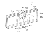
- FIG. 2 is a see-through perspective view of a positive electrode plate in an example of an embodiment, in which an area including an exposed portion of the positive electrode plate in an expanded state is exaggerated.
- 1A is a view of a positive electrode plate in an expanded state according to an example of the embodiment, as viewed from the thickness direction
- FIG. 1B is an enlarged view of part A in FIG.
- FIG. 11 is a see-through perspective view of a positive electrode plate in an exaggerated manner illustrating a range including an exposed portion of the positive electrode plate in an expanded state in another example of the embodiment.
- FIG. 10A is a view of a positive electrode plate in an expanded state according to another example of the embodiment, as viewed from the thickness direction, and FIG. 10B is an enlarged view of a portion B in FIG.
- FIG. 4 is a view corresponding to FIG. 3B in another example of the embodiment.
- FIG. 4 is a view corresponding to FIG. 3B in another example of the embodiment.
- FIG. 4 is a view corresponding to FIG. 3B in another embodiment of the present invention.
- nonaqueous electrolyte secondary battery according to the present disclosure will be described in detail with reference to the drawings. Note that the nonaqueous electrolyte secondary battery according to the present disclosure is not limited to the embodiment described below.
- the positive electrode mixture layers 31a, 31b contain a positive electrode active material, a conductive agent such as acetylene black, and a binder such as polyvinylidene fluoride (PVdF), and are preferably formed on both sides of the positive electrode core 30.
- the thickness of the positive electrode mixture layers 31a, 31b is, for example, 40 ⁇ m or more and 100 ⁇ m or less.
- a lithium transition metal complex oxide containing Ni, Co, Mn, Al, etc. is used as the positive electrode active material. It is preferable that the positive electrode tab 20 is directly bonded to the positive electrode core 30 by ultrasonic welding or the like.
- Each exposed portion 33a, 33b has a rectangular shape when viewed from the thickness direction of the positive electrode plate 11.
- Each exposed portion 33a, 33b is formed by not applying a positive electrode mixture slurry to the positive electrode core 30 and not providing a positive electrode mixture layer 31.
- the exposed portions 33a, 33b may be formed by peeling off a part of the positive electrode mixture layer 31.
- the two exposed portions 33a, 33b are formed so as to contact only one side edge in the short direction of the positive electrode plate 11. Therefore, since the positive electrode mixture layers 31a, 31b are present on the other short side of the two exposed portions 33a, 33b, a higher capacity battery can be achieved compared to the case where the exposed portions are formed over both ends of the short direction of the positive electrode plate 11.
- the position where the exposed portions 33a, 33b are formed is not limited to the center of the positive electrode plate 11 in the longitudinal direction, but may be in the middle of the longitudinal direction spaced apart from both ends of the positive electrode plate 11.
- the exposed portions 33a and 33b may be formed at a position offset toward one end of the positive electrode plate 11 in the longitudinal direction, or at multiple positions spaced apart from each other in the longitudinal direction.
- the positive electrode tab 20 shown in FIG. 1 is joined to one of the exposed portions 33a, 33b, for example, the first exposed portion 33a on the first surface of the positive electrode core 30.
- the positive electrode tab 20 is connected to one end side of the positive electrode core 30 in the short side direction, in a range not exceeding the center in the short side direction. This allows the overlap length of the positive electrode tab 20 with the positive electrode core 30 to be shortened, so that the positive electrode tab 20 can be excluded from the vicinity of the center in the winding axis direction of the electrode body 14. This makes it easier to prevent the positive electrode tab 20 inside the battery from breaking through the separator, etc., even if the battery is subjected to external impact or stress. This improves the safety of the nonaqueous electrolyte secondary battery 10.
- each exposed portion 33a, 33b may be formed in a range from one end side of the short side direction of the positive electrode core 30 beyond the center in the short side direction.
- the first exposed portion 33a has a first edge portion E1 and a second edge portion E2 that are spaced apart from each other in the longitudinal direction and extend along the short side, and a third edge portion E3 that extends along the longitudinal direction.
- the first edge portion E1 is located at the start of the winding, and the second edge portion E2 is located at the end of the winding. Therefore, the second edge portion E2 is located closer to the end of the winding than the first edge portion E1.
- the second exposed portion 33b has a first edge portion F1 and a second edge portion F2 that are spaced apart in the longitudinal direction and extend along the short side, and a third edge portion F3 that extends along the longitudinal direction.
- the first edge portion F1 is located at the start of the winding, and the second edge portion F2 is located at the end of the winding. Therefore, the second edge portion F2 is located closer to the end of the winding than the first edge portion F1.
- the edges and points located on the back side of the positive electrode plate 11 are indicated by symbols in parentheses.
- the shortest distance in the short side direction between point A1, which is a corner of the first exposed portion 33a, and point B1, which is a corner of the second exposed portion 33b is 0.5 mm or more.
- the shortest distance in the short side direction between point A2, which is a corner of the first exposed portion 33a, and point B2, which is a corner of the second exposed portion 33b is also 0.5 mm or more. This increases the effect of suppressing damage to the positive electrode plate 11.
- the shortest distance in the short side direction between point A1a, which is a corner of the first exposed portion 34a, and point B1a, which is a corner of the second exposed portion 34b is 0.5 mm or more.
- the shortest distance in the short side direction between point A2a, which is a corner of the first exposed portion 34a, and point B2a, which is a corner of the second exposed portion 34b is also 0.5 mm or more. This increases the effect of suppressing damage to the positive electrode plate 11a during charging and discharging.
- the other configurations and functions are the same as those in Figures 1 to 3.
- FIG. 7 is a diagram corresponding to FIG. 3(b) in another embodiment.
- the first exposed portion 36a when the positive electrode plate 11c is viewed in the thickness direction, the first exposed portion 36a has a first edge portion E1c and a second edge portion E2c that are spaced apart in the longitudinal direction of the positive electrode plate 11c and that are aligned along the short side, and a third edge portion E3c that is aligned along the longitudinal direction.
- the first edge portion E1c and the second edge portion E2c have the same length.
- the corners of the first exposed portion 36a are not points, but are a straight line portion G1 that connects points A1c and A2c, and a straight line portion G2 that connects points A3c and A4c.
- the straight line portion G1 corresponds to the first corner
- the straight line portion G2 corresponds to the second corner.
- the second exposed portion 36b has the same shape as the first exposed portion 36a, but the first edge portion F1c and the second edge portion F2c are shorter than the first edge portion E1c and the second edge portion E2c of the first exposed portion 36a, respectively. Therefore, when the positive electrode plate 11c is viewed in the thickness direction, the straight line portion H1 and the straight line portion H2, which are the two corners of the second exposed portion 36b, are shifted in the short direction from the straight line portion G1 and the straight line portion G2 of the first exposed portion 36a, respectively.
- the straight line portion H1 corresponds to the first corner portion
- the straight line portion H2 corresponds to the second corner portion.
- FIG. 8 is a diagram corresponding to FIG. 3(b) in another example of the embodiment.
- the first exposed portion 37a of the positive electrode plate 11d is trapezoidal, and the second exposed portion 37b is rectangular.
- the first edge portion E1d and the second edge portion E2d of the first exposed portion 37a are each aligned along the short side direction of the positive electrode plate 11d.
- the corner portion sandwiched between the first edge portion E1d and the third edge portion E3d is an arc-shaped curved portion J connecting points A1d and A3d.
- the curved portion J corresponds to the first corner portion.
- point B1d which is the corner sandwiched between the first edge portion F1d and the third edge portion F3d of the second exposed portion 37b, and curved portion J, which is a corner of the first exposed portion 37a, are offset from each other in the short side direction.
- Point B1d corresponds to the first corner portion.
- the other configurations and functions are the same as those in FIG. 6.
- the corner portion sandwiched between the first edge portion and the second edge portion may be a point, a straight portion, or a curved portion.
- only the pair of second corner portions out of the pair of first corner portions and the pair of second corner portions in the first exposed portion and the second exposed portion may be configured to be offset from each other in the short direction.
- the electrode plate having an exposed portion only in a portion of the short side direction is described as a positive electrode plate, but the negative electrode plate may have an exposed portion only in a portion of the short side direction on both sides in the thickness direction.
- damage to the negative electrode plate such as damage to the negative electrode core body during charging and discharging, can be suppressed, regardless of the configuration in which the negative electrode plate has an exposed portion only in a portion of the short side direction.
- Nonaqueous electrolyte secondary battery When the one electrode plate is developed into a plane and viewed in the thickness direction, the shortest distance between the pair of corners of the at least one electrode plate in the short-side direction is 0.5 mm or more. 2. The nonaqueous electrolyte secondary battery according to claim 1.
- Configuration 3 When the one electrode plate is developed into a plane and viewed from the thickness direction, the first edge portion and the second edge portion of the first exposed portion and the first edge portion and the second edge portion of the second exposed portion are respectively located at the same positions in the longitudinal direction. 3. The nonaqueous electrolyte secondary battery according to claim 1 or 2.
- Configuration 4 The one electrode plate is the positive electrode plate, 4. The nonaqueous electrolyte secondary battery according to any one of claims 1 to 3.
Landscapes
- Chemical & Material Sciences (AREA)
- Engineering & Computer Science (AREA)
- Chemical Kinetics & Catalysis (AREA)
- Electrochemistry (AREA)
- General Chemical & Material Sciences (AREA)
- Materials Engineering (AREA)
- Manufacturing & Machinery (AREA)
- Secondary Cells (AREA)
Priority Applications (2)
| Application Number | Priority Date | Filing Date | Title |
|---|---|---|---|
| JP2025537810A JPWO2025028226A1 (https=) | 2023-07-31 | 2024-07-12 | |
| CN202480048222.2A CN121548879A (zh) | 2023-07-31 | 2024-07-12 | 非水电解质二次电池 |
Applications Claiming Priority (2)
| Application Number | Priority Date | Filing Date | Title |
|---|---|---|---|
| JP2023-124506 | 2023-07-31 | ||
| JP2023124506 | 2023-07-31 |
Publications (1)
| Publication Number | Publication Date |
|---|---|
| WO2025028226A1 true WO2025028226A1 (ja) | 2025-02-06 |
Family
ID=94395126
Family Applications (1)
| Application Number | Title | Priority Date | Filing Date |
|---|---|---|---|
| PCT/JP2024/025230 Pending WO2025028226A1 (ja) | 2023-07-31 | 2024-07-12 | 非水電解質二次電池 |
Country Status (3)
| Country | Link |
|---|---|
| JP (1) | JPWO2025028226A1 (https=) |
| CN (1) | CN121548879A (https=) |
| WO (1) | WO2025028226A1 (https=) |
Cited By (1)
| Publication number | Priority date | Publication date | Assignee | Title |
|---|---|---|---|---|
| WO2026063121A1 (ja) * | 2024-09-19 | 2026-03-26 | パナソニックIpマネジメント株式会社 | 電極板および蓄電装置 |
Citations (9)
| Publication number | Priority date | Publication date | Assignee | Title |
|---|---|---|---|---|
| JP2003068271A (ja) | 2001-06-13 | 2003-03-07 | Matsushita Electric Ind Co Ltd | リチウム二次電池及びこの電池に用いる正極板の製造方法 |
| JP2011146219A (ja) * | 2010-01-14 | 2011-07-28 | Panasonic Corp | 非水系二次電池用電極群およびこれを用いた非水系二次電池 |
| WO2018079291A1 (ja) * | 2016-10-26 | 2018-05-03 | 三洋電機株式会社 | 非水電解質二次電池用電極及び非水電解質二次電池 |
| WO2018079292A1 (ja) * | 2016-10-26 | 2018-05-03 | 三洋電機株式会社 | 非水電解質二次電池用電極及び非水電解質二次電池 |
| US20210203044A1 (en) * | 2017-10-11 | 2021-07-01 | Samsung Sdi Co., Ltd. | Electrode assembly and secondary battery comprising same |
| CN114094044A (zh) * | 2021-11-18 | 2022-02-25 | 珠海冠宇电池股份有限公司 | 极片和电池 |
| WO2022138625A1 (ja) * | 2020-12-23 | 2022-06-30 | 三洋電機株式会社 | 非水電解質二次電池 |
| JP2022537227A (ja) * | 2020-05-20 | 2022-08-25 | 寧徳新能源科技有限公司 | 電極アセンブリ及び電池 |
| JP2022537471A (ja) * | 2020-05-20 | 2022-08-26 | 寧徳新能源科技有限公司 | 電極アセンブリ及び電池 |
-
2024
- 2024-07-12 CN CN202480048222.2A patent/CN121548879A/zh active Pending
- 2024-07-12 JP JP2025537810A patent/JPWO2025028226A1/ja active Pending
- 2024-07-12 WO PCT/JP2024/025230 patent/WO2025028226A1/ja active Pending
Patent Citations (9)
| Publication number | Priority date | Publication date | Assignee | Title |
|---|---|---|---|---|
| JP2003068271A (ja) | 2001-06-13 | 2003-03-07 | Matsushita Electric Ind Co Ltd | リチウム二次電池及びこの電池に用いる正極板の製造方法 |
| JP2011146219A (ja) * | 2010-01-14 | 2011-07-28 | Panasonic Corp | 非水系二次電池用電極群およびこれを用いた非水系二次電池 |
| WO2018079291A1 (ja) * | 2016-10-26 | 2018-05-03 | 三洋電機株式会社 | 非水電解質二次電池用電極及び非水電解質二次電池 |
| WO2018079292A1 (ja) * | 2016-10-26 | 2018-05-03 | 三洋電機株式会社 | 非水電解質二次電池用電極及び非水電解質二次電池 |
| US20210203044A1 (en) * | 2017-10-11 | 2021-07-01 | Samsung Sdi Co., Ltd. | Electrode assembly and secondary battery comprising same |
| JP2022537227A (ja) * | 2020-05-20 | 2022-08-25 | 寧徳新能源科技有限公司 | 電極アセンブリ及び電池 |
| JP2022537471A (ja) * | 2020-05-20 | 2022-08-26 | 寧徳新能源科技有限公司 | 電極アセンブリ及び電池 |
| WO2022138625A1 (ja) * | 2020-12-23 | 2022-06-30 | 三洋電機株式会社 | 非水電解質二次電池 |
| CN114094044A (zh) * | 2021-11-18 | 2022-02-25 | 珠海冠宇电池股份有限公司 | 极片和电池 |
Cited By (1)
| Publication number | Priority date | Publication date | Assignee | Title |
|---|---|---|---|---|
| WO2026063121A1 (ja) * | 2024-09-19 | 2026-03-26 | パナソニックIpマネジメント株式会社 | 電極板および蓄電装置 |
Also Published As
| Publication number | Publication date |
|---|---|
| JPWO2025028226A1 (https=) | 2025-02-06 |
| CN121548879A (zh) | 2026-02-17 |
Similar Documents
| Publication | Publication Date | Title |
|---|---|---|
| JP6250567B2 (ja) | 密閉型電池 | |
| JP6254102B2 (ja) | 密閉型電池 | |
| EP2139057B1 (en) | Electrode assembly and lithium secondary battery using the same | |
| JP6735445B2 (ja) | 捲回型電池 | |
| JP6112338B2 (ja) | 二次電池 | |
| CN106030850B (zh) | 圆筒形密闭电池 | |
| CN106207070B (zh) | 二次电池 | |
| WO2018061381A1 (ja) | 非水電解質二次電池 | |
| KR101063099B1 (ko) | 필름상 외장체를 갖는 전지 | |
| KR20150119664A (ko) | 커브드 이차 전지 | |
| JP2004356085A (ja) | ジェリーロール型の電極組立体とこれを採用した二次電池 | |
| JP2017112055A (ja) | 密閉型電池 | |
| WO2013031056A1 (ja) | 角形電池 | |
| WO2017098690A1 (ja) | 電池 | |
| WO2025028226A1 (ja) | 非水電解質二次電池 | |
| JP2017139085A (ja) | 密閉型電池 | |
| JP7129466B2 (ja) | 密閉型電池 | |
| WO2024181051A1 (ja) | 円筒形電池 | |
| WO2024247779A1 (ja) | 円筒形電池 | |
| JP2021168284A (ja) | 蓄電素子 | |
| WO2024247781A1 (ja) | 円筒形電池 | |
| WO2026094792A1 (ja) | 円筒形電池 | |
| WO2024181038A1 (ja) | 円筒形電池 | |
| US20240106043A1 (en) | Pouch-Type Secondary Battery | |
| WO2025183002A1 (ja) | 非水電解質二次電池 |
Legal Events
| Date | Code | Title | Description |
|---|---|---|---|
| 121 | Ep: the epo has been informed by wipo that ep was designated in this application |
Ref document number: 24848883 Country of ref document: EP Kind code of ref document: A1 |
|
| WWE | Wipo information: entry into national phase |
Ref document number: 202617005337 Country of ref document: IN |
|
| ENP | Entry into the national phase |
Ref document number: 2025537810 Country of ref document: JP Kind code of ref document: A |
|
| WWE | Wipo information: entry into national phase |
Ref document number: 2025537810 Country of ref document: JP |
|
| WWE | Wipo information: entry into national phase |
Ref document number: 2024848883 Country of ref document: EP |
|
| NENP | Non-entry into the national phase |
Ref country code: DE |