WO2025028126A1 - 作業支援装置および作業支援方法 - Google Patents
作業支援装置および作業支援方法 Download PDFInfo
- Publication number
- WO2025028126A1 WO2025028126A1 PCT/JP2024/023889 JP2024023889W WO2025028126A1 WO 2025028126 A1 WO2025028126 A1 WO 2025028126A1 JP 2024023889 W JP2024023889 W JP 2024023889W WO 2025028126 A1 WO2025028126 A1 WO 2025028126A1
- Authority
- WO
- WIPO (PCT)
- Prior art keywords
- maintenance
- support device
- image
- work
- abnormality
- Prior art date
- Legal status (The legal status is an assumption and is not a legal conclusion. Google has not performed a legal analysis and makes no representation as to the accuracy of the status listed.)
- Pending
Links
Images






Classifications
-
- G—PHYSICS
- G05—CONTROLLING; REGULATING
- G05B—CONTROL OR REGULATING SYSTEMS IN GENERAL; FUNCTIONAL ELEMENTS OF SUCH SYSTEMS; MONITORING OR TESTING ARRANGEMENTS FOR SUCH SYSTEMS OR ELEMENTS
- G05B23/00—Testing or monitoring of control systems or parts thereof
- G05B23/02—Electric testing or monitoring
-
- G—PHYSICS
- G06—COMPUTING OR CALCULATING; COUNTING
- G06Q—INFORMATION AND COMMUNICATION TECHNOLOGY [ICT] SPECIALLY ADAPTED FOR ADMINISTRATIVE, COMMERCIAL, FINANCIAL, MANAGERIAL OR SUPERVISORY PURPOSES; SYSTEMS OR METHODS SPECIALLY ADAPTED FOR ADMINISTRATIVE, COMMERCIAL, FINANCIAL, MANAGERIAL OR SUPERVISORY PURPOSES, NOT OTHERWISE PROVIDED FOR
- G06Q10/00—Administration; Management
- G06Q10/20—Administration of product repair or maintenance
-
- G—PHYSICS
- G06—COMPUTING OR CALCULATING; COUNTING
- G06Q—INFORMATION AND COMMUNICATION TECHNOLOGY [ICT] SPECIALLY ADAPTED FOR ADMINISTRATIVE, COMMERCIAL, FINANCIAL, MANAGERIAL OR SUPERVISORY PURPOSES; SYSTEMS OR METHODS SPECIALLY ADAPTED FOR ADMINISTRATIVE, COMMERCIAL, FINANCIAL, MANAGERIAL OR SUPERVISORY PURPOSES, NOT OTHERWISE PROVIDED FOR
- G06Q50/00—Information and communication technology [ICT] specially adapted for implementation of business processes of specific business sectors, e.g. utilities or tourism
- G06Q50/06—Energy or water supply
-
- G—PHYSICS
- G06—COMPUTING OR CALCULATING; COUNTING
- G06T—IMAGE DATA PROCESSING OR GENERATION, IN GENERAL
- G06T7/00—Image analysis
-
- G—PHYSICS
- G06—COMPUTING OR CALCULATING; COUNTING
- G06T—IMAGE DATA PROCESSING OR GENERATION, IN GENERAL
- G06T7/00—Image analysis
- G06T7/70—Determining position or orientation of objects or cameras
Definitions
- the present invention relates to a work support device and a work support method that support work.
- abnormalities include oil leaks from oil tanks and (traces of) leaked oil.
- maintenance personnel When an abnormality is discovered, maintenance personnel must take a photo of the abnormal area with a camera and record the facility or equipment where it was discovered, as well as the location.
- problems can arise, such as abnormalities being overlooked or recorded inaccurately.
- One method for supporting maintenance work is to use a head mounted display (HMD) equipped with a see-through display.
- the head mounted display can support maintenance work by informing maintenance personnel of maintenance procedures and displaying manuals for facilities and equipment. Furthermore, if the head mounted display can point out the part/component that is the target of work in the facilities or equipment by using augmented reality (AR) technology or mixed reality (MR) technology, the efficiency of maintenance work can be improved.
- AR augmented reality
- MR mixed reality
- the method described in Patent Document 1 is a method for inspecting an object using augmented reality, in which three-dimensional measurement data of the object is acquired, and the measurement data and a camera image of the object are displayed.
- Patent Document 1 In the method described in Patent Document 1, in order to obtain three-dimensional measurement data, it is necessary to prepare a marker (AR marker), which is time-consuming. Furthermore, Patent Document 1 does not contain any description related to abnormality detection. It is desired that a head-mounted display can support and improve the efficiency of work not only in maintenance work but also in work on various objects, such as product manufacturing work.
- the present invention has been made in view of the above background, and an object of the present invention is to provide a work support device and a work support method that enable efficient work support.
- the work support device of the present invention includes a detection unit that detects the position and orientation of an object by comparing at least one of the following four items acquired from a sensor: 3D spatial information of an object being worked on, 3D spatial information of surrounding objects around the object, an image of the object, and an image of the surrounding objects with a 3D model of the object, and detects abnormalities related to the object or the surrounding objects based on the image of the object or the surrounding objects; and a support unit that calculates the position of the object or the surrounding object where the abnormality is located and displays a marker for that position.
- the present invention provides a work support device and a work support method that enable efficient work support. Problems, configurations, and effects other than those described above will become clear from the description of the following embodiments.
- FIG. 4 is a flowchart showing a procedure of a maintenance operation according to the embodiment.
- 1 is a diagram showing a pointer displayed on a transmissive display of the work support device according to the present embodiment, and a transformer facility as a scene seen through the transmissive display.
- 1 is a diagram showing a message displayed on a transmissive display according to the present embodiment, and a transformer facility as a scene seen through the transmissive display.
- 1 is a diagram showing a message and a marker displayed on a transmissive display according to this embodiment, and a transformer facility as a scene seen through the transmissive display.
- 1 is a functional block diagram of a work support device according to an embodiment of the present invention.
- 10 is a flowchart of a work support process according to the present embodiment.
- 11 is a flowchart of a support process corresponding to an operation of checking for oil leakage as an abnormality of the conservator according to the present embodiment.
- 5A and 5B are diagrams for explaining an image region that is a detection target according to the present embodiment.
- 11 is a flowchart of a support process corresponding to a task of recording values indicated by instruments according to the present embodiment.
- the work support device is a head-mounted display equipped with a see-through display device.
- the work support device detects the position of the maintenance worker who wears the device and indicates the direction of the facility or equipment to be maintained, thereby guiding the maintenance worker to the facility or equipment.
- the work support device calculates the positional relationship and orientation between the maintenance worker and the maintenance object by comparing an image captured by a camera or a three-dimensional point cloud acquired by a depth sensor with a three-dimensional model of the maintenance object.
- the maintenance object object to be maintained
- the work support device displays the maintenance procedure when the maintenance worker arrives at the transformer equipment.
- One of the maintenance tasks for transformer equipment is to check for oil leaks in the conservator (oil tank).
- the work support device guides the maintenance worker to the location of the conservator or points out the conservator (see Figure 3 below) and instructs the maintenance worker to check for oil leaks or signs of oil leaks in the conservator or its surroundings.
- the work support device detects oil leaks in camera images, particularly in images that the maintenance worker is looking at, and asks the maintenance worker to check.
- the work support device records the image and location of the oil leak.
- the work support device also displays a marker at the location of the oil leak.
- Such a work support device reduces the amount of work required for maintenance personnel to refer to manuals and record maintenance procedures. In addition, because the work support device detects abnormalities (oil leaks), it reduces the number of abnormalities that go unnoticed. This in turn improves the efficiency of maintenance work.
- FIG 1 is a flowchart showing the procedure of the maintenance work according to this embodiment.
- FIG 1 an overview of the procedure of the maintenance work performed by a maintenance worker wearing the work support device 100, which is a head-mounted display, on a maintenance target will be described.
- step S11 the maintenance worker uses pointer 511 (see FIG. 2, described below) to move to the location of the facility or equipment to be maintained.
- the maintenance target is a transformer facility.
- FIG. 2 is a diagram showing a pointer 511 displayed on a transparent display 181 (see FIG. 7 described later) of the work support device 100 according to this embodiment, and a transformer facility 400 as a scene seen through the transparent display 181.
- the work support device 100 is equipped with a transparent display 181.
- a maintenance worker sees the view ahead seen through the transparent display 181 superimposed on the image displayed on the transparent display 181. Note that the image appears three-dimensional due to binocular stereoscopic vision.
- the work support device 100 is equipped with an accelerometer and a gyroscope, and constantly (periodically) detects its own position and orientation. Even if the maintenance worker moves or turns his head, the work support device 100 displays a pointer 511 on the transmissive display 181 so that it points to the transformer equipment 400.
- step S12 the maintenance worker performs step S12 as the next work.
- the maintenance worker may perform step S12 after uttering "arrived” or "started work”.
- step S12 the maintenance person starts the process of repeating the work in step S13.
- step S13 the maintenance person performs the work in accordance with the work instructions (see message 521 in FIG. 3 described later) displayed on the transmissive display 181.
- the work will be described using an example of checking for oil leakage as an abnormality in the conservator.
- FIG. 3 shows a message 521 and a pointer 522 displayed on the transparent display 181 according to this embodiment, and the transformer equipment 400 as a scene seen through the transparent display 181.
- the message 521 instructs the maintenance worker to check for oil leaks in the conservator 410 and to record the location of any oil leaks that may be present.
- the pointer 522 points to the conservator 410 as the target of the work.
- the maintenance worker looks at the conservator 410 and below it to check for oil leaks. The following explanation will be continued assuming that there is an oil leak 523 (traces of oil leaks).
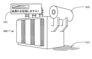
- FIG. 4 is a diagram showing a message 531 displayed on the transmissive display 181 according to this embodiment, and the transformer facility 400 as a scene seen through the transmissive display 181.
- the work support device 100 detects and photographs an oil leak 523.
- the message 531 asks the maintenance worker whether to record the oil leak 523. If the maintenance worker says “No,” the work support device 100 does not record anything. If the maintenance worker says “Yes,” the work support device 100 displays a message 541 (see FIG. 5, described below).
- FIG. 5 is a diagram showing a message 541, an area 542, and a three-dimensional axis 543 displayed on the transmissive display 181 according to this embodiment, and the transformer equipment 400 as a scene seen through the transmissive display 181.
- the message 541 asks the maintenance worker whether it is appropriate to record the captured image in area 542 as an image of an abnormality, and to record the position indicated by the three-dimensional axis 543 as the position of the abnormality. If the maintenance worker says "Yes,” the work support device 100 stores the image of the oil leak 523 shown in area 542, the position indicated by the three-dimensional axis 543, the confirmation date and time, etc., as records related to the conservator 410 of the transformer equipment 400. If the maintenance worker says "No,” the work support device 100 does not record.
- FIG. 6 is a diagram showing a message 551 and a marker 552 displayed on the transparent display 181 according to this embodiment, and the transformer facility 400 as a scene seen through the transparent display 181.
- the message 551 indicates that an image of the oil leak 523 as an abnormality and the position indicated by the marker 552 have been stored as a record of the maintenance work related to the conservator 410.
- the position indicated by the marker 552 is recorded as a relative position as seen from the transformer facility 400, for example. Even if the maintenance worker moves or changes the direction of his/her head, the work support device 100 displays the marker 552 on the transparent display 181 so that the marker 552 is at the recorded position (the position indicated by the three-dimensional axis 543 in FIG. 5). In this way, the work support device 100 detects the oil leak 523 as an abnormality and records the position of the oil leak 523.
- the maintenance worker may also record anything he or she notices, such as the cause of an oil leak, as a comment. For example, the maintenance worker may say “comment” to instruct the system to record the audio that follows, or to convert it to text and record it. The maintenance worker may also say “take a picture” to instruct the system to record the image captured by the camera.
- Maintenance work related to the oil leakage abnormality of the conservator 410 includes, for example, damage, cracks, and discoloration of the bushing 420 (see FIG. 2).
- the work support device 100 supports the maintenance work for abnormalities in the bushing 420, as well as the oil leakage 523, by indicating the bushing 420 (see pointer 522 in FIG. 3), detecting the abnormality (see message 531 in FIG. 4), and recording it.
- the abnormality may be other abnormalities, for example rust on the transformer equipment 400.
- the work support device 100 reads and records the displayed numbers and the numbers indicated by the instruments.
- the work support device 100 may also photograph the instruments and record the images.
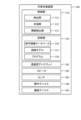
- ⁇ Configuration of the work support device> 7 is a functional block diagram of a work support device 100 according to this embodiment.
- the work support device 100 is a computer also called a head-mounted display.
- the work support device 100 includes a control unit 110, a storage unit 120, a transmissive display 181, a speaker 182, a sensor 183, an operation device 184, and a communication device 185.
- the transmissive display 181 is capable of displaying three-dimensional CG images. To a maintenance worker wearing the work support device 100, which is a head-mounted display, a CG image of an object appears to exist three-dimensionally in the physical world seen through the transmissive display 181.
- the sensor 183 includes a microphone, a camera, a depth sensor, an accelerometer, and a gyroscope.
- the camera includes a camera for capturing an image in front of the work support device 100, which is a head-mounted display, as well as a camera for detecting the line of sight of a maintenance worker wearing the work support device 100.
- the camera may be an infrared camera for detecting the pupil.
- the depth sensor measures the shape of an object in front of the work support device 100 and outputs it as three-dimensional spatial information (three-dimensional point cloud information). Based on the measurement results of the accelerometer and gyroscope, the position (relative position from a reference point) and orientation of the work support device 100 can be calculated.
- the sensor 183 may further include a Global Navigation Satellite System (GNSS) antenna and a geomagnetic sensor. The position and orientation of the work assistance device 100 can be calculated based on information from these sensors.
- the operation device 184 is, for example, a button or a dial for operating the work assistance apparatus 100.
- the communication device 185 is, for example, a device for wireless communication.
- the storage unit 120 includes storage devices such as a read only memory (ROM), a random access memory (RAM), a flash memory, etc.
- the storage unit 120 stores a maintenance information database 130, a recognition model 121, and a program 128.
- the program 128 includes a description of a task support process (see FIG. 8, which will be described later).
- the maintenance information database 130 stores information relating to maintenance targets such as facilities and equipment, such as names, positions of maintenance targets, images, three-dimensional models, maintenance procedures, maintenance records, and the like.
- the maintenance information database 130 may store not only information related to the facilities and devices themselves that are the targets of maintenance, but also information related to the parts/portions that constitute the targets of maintenance, such as names, relative positions from the targets of maintenance, images, three-dimensional models, maintenance procedures, maintenance records, etc.
- the maintenance information database 130 may also store map information of the areas surrounding the targets of maintenance.
- the recognition model 121 is a machine learning model used to detect (recognize, detect) a maintenance target, a part/portion of the maintenance target, and an abnormality, and is, for example, a model of deep learning technology.
- the recognition model 121 may be a plurality of recognition models 121 according to the detection target. For example, there may be a recognition model 121 for each detection target (recognition target, detection target) of the maintenance target, the part/portion of the maintenance target, and the abnormality.
- the control unit 110 includes a central processing unit (CPU) and includes a detection unit 111, a support unit 112, and a gaze detection unit 113.
- the control unit 110 may include a processor such as a graphics processing unit (GPU), a field programmable gate array (FPGA), or an application specific integrated circuit (ASIC).
- the control unit 110 may also include a processor that performs processing (holographic processing) to make the image displayed on the transmissive display 181 appear three-dimensional.
- the detection unit 111 detects a maintenance target based on information acquired by the sensor 183, and acquires a relative position and orientation with respect to the work support device 100. For example, the detection unit 111 acquires the position and orientation of the maintenance target by comparing three-dimensional space information (three-dimensional point cloud information) acquired by a depth sensor provided in the sensor 183 with a three-dimensional model of the maintenance target stored in the maintenance information database 130.
- three-dimensional space information three-dimensional point cloud information
- the detection unit 111 may also detect the maintenance target using the recognition model 121 based on an image acquired by a camera provided in the sensor 183, and detect the position and orientation of the maintenance target based on the image by comparing it with a three-dimensional model. Furthermore, the detection unit 111 may combine the three-dimensional model with three-dimensional spatial information and the image to detect the maintenance target and acquire the relative position and orientation.
- the detection unit 111 detects the position and orientation of the maintenance target (transformation equipment 400) by comparing the three-dimensional spatial information and images of the maintenance target and surrounding objects (e.g., the ground) with the three-dimensional model. In addition, the detection unit 111 detects parts/parts that make up the maintenance target in the same way as the maintenance target, and obtains the relative positions and orientations.
- the detection unit 111 also uses the recognition model 121 based on the image acquired by the camera to detect an abnormality related to the maintenance target.
- An example of an abnormality is an oil leak 523 (see Figures 3 to 6) in a conservator (oil tank) that constitutes the transformer equipment that is the maintenance target.
- the detection unit 111 detects the oil leak 523 (oil stain) on the main body of the conservator 410 or on the ground below the conservator 410, and calculates its position. Note that this position is a position in three-dimensional space, and can be calculated based on the position and orientation of the work support device 100 and the position of the abnormality (oil leak 523) in the image. This position may be calculated by the support unit 112, described below, instead of the detection unit 111.
- detection unit 111 may narrow down the images to be detected to images of the main body of conservator 410 and the ground below conservator 410. This is because oil leakage 523 is often found around conservator 410. The range of images to be detected may be narrowed down depending on the type of abnormality. In this way, detection unit 111 can efficiently detect abnormalities.
- the detection unit 111 detects components provided in the maintenance target and acquires their status. For example, the detection unit 111 detects instruments provided in the maintenance target and reads the values indicated by the needles or the displayed values, or detects valves and acquires the open/closed state.
- the work support device 100 includes a detection unit 111 that detects the position and orientation of a work target object (see transformation equipment 400) by comparing at least one of the following four items acquired from the sensor 183 with a three-dimensional model of the object: three-dimensional spatial information of the work target object, three-dimensional spatial information of surrounding objects (e.g., the ground) around the object, an image of the object, and an image of the surrounding objects. Furthermore, the detection unit 111 detects an abnormality (see oil leak 523) related to an object or a surrounding object based on an image of the object or a surrounding object.
- an abnormality see oil leak 523
- the anomaly is an anomaly that relates to a part of the object (see conservator 410).
- the detection unit 111 detects abnormalities based on images of the part and the surrounding area of the part (the ground below the conservator 410).
- the support unit 112 supports the maintenance work by displaying a pointer indicating the facility, device, or part/part to be maintained, showing the maintenance procedure, and acquiring records. For example, the support unit 112 displays a pointer indicating the facility, device, or part/part on the transmissive display 181 (see pointer 511 in FIG. 2 and pointer 522 in FIG. 3) based on the position of the facility, device, or part/part acquired by the detection unit 111. In addition, for example, the support unit 112 displays a maintenance procedure or a confirmation message (see messages 521 and 531 in FIG. 3 and FIG. 4). In addition, the support unit 112 calculates the position of the abnormality and displays a marker 552 (see FIG. 6) indicating the position.
- the support unit 112 changes the position and orientation of the displayed pointers 511, 522 and marker 552 according to the position and orientation of the work support device 100 acquired by the accelerometer and gyroscope. Additionally, the support unit 112 records in the maintenance information database 130 images and positions indicating abnormalities acquired by the detection unit 111, numerical values of instruments read by the detection unit 111, and the like.
- the gaze detection unit 113 calculates the gaze (direction of gaze) of the maintenance worker based on the positions of the iris and pupil captured by the camera. More specifically, the gaze detection unit 113 calculates the gaze at the timing when the maintenance worker checks an abnormality or checks instruments, and outputs the calculation result to the detection unit 111.
- the detection unit 111 detects abnormalities and instruments by narrowing down the image to be subjected to detection processing to the image around the gaze point, rather than the entire image captured by the camera. In this way, the detection unit 111 can efficiently detect abnormalities.
- the work support device 100 includes a support unit 112 that calculates the position of an object (target object, see transformer equipment 400) having an abnormality (see oil leak 523) or a surrounding object (e.g., the ground) and displays a marker 552 of that position (marker 552 indicating that position).
- the support unit 112 displays a pointer 522 (see FIG. 3) that points to a part of the object where an abnormality may occur (see the conservator 410).
- the work assistance device 100 is equipped with a transmissive display 181 .
- the sensor 183 acquires the position and orientation of the work assistance device 100 .
- the support unit 112 changes the position and orientation of the marker 552 to be displayed according to the position and orientation acquired by the sensor 183 , and displays the marker 552 on the transmissive display 181 .
- the support unit 112 records the location and image of the abnormality.
- the work assistance device 100 includes a gaze detection unit 113 that detects the gaze of a worker wearing the work assistance device 100 .
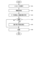
- Fig. 8 is a flowchart of the work support process according to this embodiment.
- the work support process of the work support device 100 corresponding to the maintenance work procedure shown in Fig. 1 will be described with reference to Fig. 8.
- the maintenance target is the transformer facility 400 (see Fig. 2).
- the support unit 112 guides the maintenance worker to the facility/equipment that is the target of maintenance.
- the support unit 112 may calculate the relative position of the maintenance target as seen by the maintenance worker based on the positional relationship between the maintenance worker and the maintenance target, and guide the worker by displaying a graphic (e.g., an arrow) indicating the direction of the maintenance target on the transparent display 181.
- a graphic e.g., an arrow
- the support unit 112 may display a pointer 511 (see FIG. 2) to guide the worker.
- the location of the maintenance target and map information about the surrounding area are stored in the maintenance information database 130.
- the location and orientation of the maintenance worker before starting guidance may be set by the maintenance worker, or may be calculated based on the output results of the GNSS antenna and geomagnetic sensor equipped in the work support device 100.
- step S22 the detection unit 111 detects the maintenance target and obtains the relative position and orientation. Note that steps S21 and S22 may be executed simultaneously in parallel, or step S22, which is a process for detecting the maintenance target, may be started from the start of guidance. Also, step S22 may be started after it is determined that the distance to the maintenance target is equal to or less than a predetermined value, or that the maintenance target is in a position where it can be seen.
- step S23 when the support unit 112 acquires the maintenance worker's utterance of "arrived” or “start work” (see step S11 in FIG. 1) via the microphone provided in the sensor 183, it acquires the maintenance procedure for the maintenance target stored in the maintenance information database 130.
- step S24 the support unit 112 repeats the process of step S25 for each maintenance procedure acquired in step S23.
- step S25 the support unit 112 executes a support process corresponding to the maintenance procedure.
- the support process corresponding to the operation of checking for oil leakage as an abnormality of the conservator 410 described with reference to FIGS. 3 to 6 will be described below.
- FIG. 9 is a flowchart of a support process corresponding to an operation of checking for oil leakage as an abnormality in the conservator 410 according to this embodiment.
- the support unit 112 displays a message 521 (see FIG. 3 ) and a pointer 522.
- the position and orientation of the transformer facility 400 which is the maintenance target as viewed from the work support device 100, have already been calculated, and the position and orientation of the conservator 410 can also be calculated.
- the detection unit 111 can also detect the conservator 410, which is a part/portion that constitutes the maintenance target, and can calculate its position and orientation.
- the support unit 112 displays the pointer 522 based on the calculated position and orientation of the conservator 410.
- step S32 the line-of-sight detection unit 113 detects the line of sight (direction of line of sight) of the maintenance worker.
- step S33 the detection unit 111 detects the oil leak 523 (see FIG. 3). More specifically, the detection unit 111 detects the oil leak 523 using the recognition model 121 based on an image acquired by a camera that captures the view in front of the work support device 100 and is included in the sensor 183. Note that the recognition model 121 may be the recognition model 121 used to detect an abnormality related to the conservator 410, particularly the oil leak 523, instead of the recognition model 121 used to detect the maintenance target (transformation equipment 400) in step S22 (see FIG. 8).
- the support unit 112 displays a message 531 (see FIG. 4).
- the detection unit 111 may narrow down the area to be detected within the image acquired by the camera.
- FIG. 10 is a diagram for explaining the image area to be detected according to this embodiment.
- Dashed line 573 indicates the line of sight (direction of line of sight) detected by the line of sight detection unit 113.
- the detection unit 111 detects the oil leak 523 by narrowing down the field of view to an area 571 (field of view) that is within a predetermined angle 572 in the direction of the dashed line 573 (line of sight).
- the detection unit 111 may refer to the three-dimensional spatial information acquired by a depth sensor included in the sensor 183, and detect the oil leak 523 by narrowing down the field of view to an area within the area 571 and in the vicinity of the transformer equipment 400 and the conservator 410.
- the detection unit 111 detects an abnormality (see oil leak 523) based on an image within the field of view (see area 571) indicated by a predetermined angle 572 centered on the line of sight (see dashed line 573).
- step S34 if the maintenance person utters "yes” and confirms the oil leak 523 (step S34 ⁇ YES), the support unit 112 advances the process to step S35. If the maintenance person utters "no" (step S34 ⁇ NO), the support unit 112 returns the process to step S33.
- These "yes” and “no” are the “yes” and “no” uttered by the maintenance person described in FIG. 4.
- step S35 the support unit 112 identifies the area 542 (see FIG. 5) of the oil leak 523 detected by the detection unit 111, and displays a message 541, a frame indicating the area 542, and a three-dimensional axis 543.
- the support unit 112 calculates the position in three-dimensional space indicated by the three-dimensional axis 543 based on the relationship between the positions and orientations of the work support device 100 and the transformer equipment 400, including the ground.
- step S36 if the maintenance worker utters "yes” to confirm the location of the oil leak 523 (step S36 ⁇ YES), the support unit 112 advances the process to step S37. If the maintenance worker utters "no" (step S36 ⁇ NO), the support unit 112 returns the process to step S35. These "yes” and “no” are the “yes” and “no” uttered by the maintenance worker described in FIG. 5.
- step S37 the support unit 112 stores an image of the area 542 and the position of its center in the maintenance information database 130 as a record of the maintenance work related to the conservator 410.
- the support unit 112 displays a message 551 and a marker 552 (see FIG. 6) at the center position of the area 542.
- FIG. 11 is a flowchart of the support process corresponding to the task of recording the values indicated by instruments according to this embodiment.
- step S41 the support unit 112 displays a message.
- This message instructs the user to record the numerical values of each meter provided in the transformer facility 400 and to confirm that the numerical values are within the normal range.
- the line-of-sight detection unit 113 detects the line of sight (direction of line of sight) of the maintenance worker.
- the detection unit 111 detects the gauge and reads the value. The process of detecting the gauge is similar to the process of detecting the oil leak 523. When the detection unit 111 reads the value, the support unit 112 displays a message to confirm whether the value is correct or not.
- step S44 if the maintenance worker says "yes” and confirms the numerical value (step S44 ⁇ YES), the support unit 112 advances the process to step S46. If the maintenance worker says “no” (step S44 ⁇ NO), the support unit 112 advances the process to step S45. The maintenance worker says "no” followed by the correct numerical value.
- step S45 the support unit 112 acquires the numerical value spoken by the maintenance worker and corrects the numerical value read in step S43.
- step S46 the support unit 112 stores and records the numerical value in the maintenance information database 130.
- the support unit 112 compares the numerical value with a normal range stored in the maintenance information database 130, and displays a message including the numerical value and the comparison result.
- the maintenance worker investigates the cause and instructs the work support device 100 to record the results of the investigation.
- the maintenance worker may say "comment” and instruct the work support device 100 to record the subsequent voice, or to convert it to text and record it.
- the maintenance worker may also say "take a picture” and instruct the work support device 100 to record the image (video) captured by the camera.
- the support unit 112 stores and records the voice, the text converted from the voice, and the captured image in the maintenance information database 130 according to the maintenance worker's instructions.
- the process of recording such comments and images (video) is not limited to the task of recording the values indicated by instruments, but is similar to other tasks, including the task of checking for oil leaks as an abnormality.
- the support unit 112 calculates and records the position of the gaze or pointed object.
- the gaze is calculated by the gaze detection unit 113.
- the pointed direction can be calculated based on an image or three-dimensional spatial information.
- the support unit 112 finds the intersection of the object (such as the transformer equipment 400 or the ground) with the gaze or pointed direction, and calculates the position.
- the work support device 100 displays a pointer 511 that guides the maintenance worker to the maintenance target (see the transformer facility 400 in FIG. 2 ) and a pointer 522 that points to the part to be maintained (see the conservator 410 in FIG. 3 ). This allows the maintenance worker to easily grasp the maintenance target and part.
- the work support device 100 detects abnormalities related to the maintenance target (see oil leak 523), calculates the position of the abnormality, and displays a marker 552 (see Figure 6). This position is in three-dimensional space, and even if the position or orientation of the work support device 100 changes, the work support device 100 displays the marker 552 as if it were in the same position. Furthermore, the work support device 100 records images and positions of abnormalities. By using such a work support device 100, maintenance personnel can reduce the amount of time spent overlooking abnormalities and recording abnormalities. Furthermore, the parties involved can hold discussions while referring to the records, allowing discussions to proceed efficiently.
- the work support device 100 When detecting an abnormality, the work support device 100 narrows the range of the image to be detected to the area 571 (see FIG. 10) around the line of sight, or the part related to the abnormality and its surroundings (for example, the conservator 410 and the ground below it). By narrowing the image range to be detected in this way, the computational resources required for the detection process can be reduced, and high-speed, high-precision detection processing becomes possible even in the work support device 100, which is a head-mounted display.
- the display device provided in the work support device 100 is the transmissive display 181, but is not limited to this.
- the work support device 100 (the support unit 112) may display a view in front of the work support device 100 captured by a camera on the display, and may further display a pointer 522 and messages 521 and 531.
Landscapes
- Engineering & Computer Science (AREA)
- Business, Economics & Management (AREA)
- General Physics & Mathematics (AREA)
- Physics & Mathematics (AREA)
- Theoretical Computer Science (AREA)
- Human Resources & Organizations (AREA)
- Economics (AREA)
- Strategic Management (AREA)
- Health & Medical Sciences (AREA)
- General Business, Economics & Management (AREA)
- Marketing (AREA)
- Tourism & Hospitality (AREA)
- Computer Vision & Pattern Recognition (AREA)
- Quality & Reliability (AREA)
- Operations Research (AREA)
- Entrepreneurship & Innovation (AREA)
- Automation & Control Theory (AREA)
- Public Health (AREA)
- Water Supply & Treatment (AREA)
- General Health & Medical Sciences (AREA)
- Primary Health Care (AREA)
- Management, Administration, Business Operations System, And Electronic Commerce (AREA)
- Image Analysis (AREA)
- Testing And Monitoring For Control Systems (AREA)
Abstract
作業支援装置(100)は、センサ(183)から取得した作業対象である物体の3次元空間情報、当該物体周辺にある周辺物体の3次元空間情報、当該物体の画像、および当該周辺物体の画像の4つのうち少なくとも1つと、当該物体の3次元モデルとを照合して、当該物体の位置および向きを検出するとともに、当該物体または当該周辺物体の画像を基に、当該物体または当該周辺物体に係る異常を検出する検出部(111)を備える。また作業支援装置(100)は、異常がある当該物体または当該周辺物体の位置を算出し、当該位置のマーカを表示する支援部(112)を備える。
Description
本発明は、作業を支援する作業支援装置および作業支援方法に関する。
設備や機器の保守作業において保守員は、設備や機器の異常(問題)を見つけ出すことが求められる。異常としては、例えばオイルタンクからの油漏れや漏れた油(の跡)などがある。異常を発見した場合に保守員は、カメラで異常な箇所を撮影し、発見した設備や機器、場所などを記録する必要がある。しかしながら、このような保守作業では、異常を見逃してしまう、不正確に記録してしまうなどの問題が発生することがある。
保守作業を支援する手法として、透過型のディスプレイを備えたヘッドマウントディスプレイ(Head Mounted Display、HMD)を用いるものがある。ヘッドマウントディスプレイが保守員に保守手順を知らせたり、設備や機器のマニュアルを表示したりすることで、保守作業を支援することができる。さらに拡張現実(Augmented Reality、AR)技術または複合現実(Mixed Reality、MR)技術を用いることで、ヘッドマウントディスプレイが設備や機器のなかの作業対象となる部分/部品を指し示すことができれば、保守作業の効率向上が望める。
特許文献1に記載の方法は、拡張現実を用いて物体を検査する方法であって、物体の3次元データ測定データを取得して、測定データと当該物体のカメラ画像とを表示する。
特許文献1に記載の方法は、拡張現実を用いて物体を検査する方法であって、物体の3次元データ測定データを取得して、測定データと当該物体のカメラ画像とを表示する。
特許文献1に記載の方法において3次元測定データを取得するにあたって、マーカ(ARマーカ)を用意する必要があり、手間が掛かる。また特許文献1には、異常の検出に係る記載は見当たらない。保守作業に限らず、例えば製品の製造作業など、様々な物体に対する作業において、ヘッドマウントディスプレイが作業を支援して、効率化することが望まれている。
本発明は、このような背景に鑑みてなされたものであり、効率的な作業の支援を可能とする作業支援装置および作業支援方法を提供することを課題とする。
本発明は、このような背景に鑑みてなされたものであり、効率的な作業の支援を可能とする作業支援装置および作業支援方法を提供することを課題とする。
上記した課題を解決するため、本発明に係る作業支援装置は、センサから取得した作業対象である物体の3次元空間情報、当該物体周辺にある周辺物体の3次元空間情報、当該物体の画像、および当該周辺物体の画像の4つのうち少なくとも1つと、当該物体の3次元モデルとを照合して、当該物体の位置および向きを検出するとともに、当該物体または当該周辺物体の画像を基に、当該物体または当該周辺物体に係る異常を検出する検出部と、当該異常がある当該物体または当該周辺物体の位置を算出し、当該位置のマーカを表示する支援部と、を備える。
本発明によれば、効率的な作業の支援を可能とする作業支援装置および作業支援方法を提供することができる。上記した以外の課題、構成および効果は、以下の実施形態の説明により明らかにされる。
≪作業支援装置の概要≫
以下に本発明を実施するための形態(実施形態)における作業支援装置について説明する。作業支援装置は、透過型の表示装置を備えたヘッドマウントディスプレイである。作業支援装置は、装着者である保守員の位置を検出して保守対象の設備や機器の方向を示すことで、保守員を設備や機器まで誘導する。この際に作業支援装置は、カメラで撮像した画像や深度センサで取得した3次元点群と、作業対象の3次元モデルを照合することで、保守員と保守対象との位置関係や向きを算出する。以下では保守対象(作業対象である物体)は変圧設備であるとする。
以下に本発明を実施するための形態(実施形態)における作業支援装置について説明する。作業支援装置は、透過型の表示装置を備えたヘッドマウントディスプレイである。作業支援装置は、装着者である保守員の位置を検出して保守対象の設備や機器の方向を示すことで、保守員を設備や機器まで誘導する。この際に作業支援装置は、カメラで撮像した画像や深度センサで取得した3次元点群と、作業対象の3次元モデルを照合することで、保守員と保守対象との位置関係や向きを算出する。以下では保守対象(作業対象である物体)は変圧設備であるとする。
作業支援装置は、保守員が変圧設備に到着すると保守手順を表示する。変圧設備の保守作業の1つに、コンサベータ(オイルタンク)の油漏れの点検がある。作業支援装置は、コンサベータのある場所に保守員を誘導したりコンサベータを指し示したりして(後記する図3参照)、コンサベータやその周辺に油漏れや油漏れの跡がないかを確認するように指示する。この際に作業支援装置は、カメラの画像、特に保守員の視線の先となる画像に写る油漏れを検出して、保守員に確認を求める。保守員が油漏れを確認すると作業支援装置は、油漏れの画像や位置を記録する。また作業支援装置は、油漏れの位置にマーカを表示するようにする。
このような作業支援装置によれば保守員による保守手順のマニュアル参照や記録の手間が減る。また作業支援装置が異常(油漏れ)を検出することで、異常の見逃しが減る。延いては、保守作業の効率が向上する。
≪保守作業の概要≫
作業支援装置100(後記する図7参照)の構成を説明する前に、保守作業の概要を説明する。図1は、本実施形態に係る保守作業の手順を示すフローチャートである。図1を参照しながら、ヘッドマウントディスプレイである作業支援装置100を装着した保守員が、保守対象に対して行う保守作業の手順の概要を説明する。
作業支援装置100(後記する図7参照)の構成を説明する前に、保守作業の概要を説明する。図1は、本実施形態に係る保守作業の手順を示すフローチャートである。図1を参照しながら、ヘッドマウントディスプレイである作業支援装置100を装着した保守員が、保守対象に対して行う保守作業の手順の概要を説明する。
ステップS11において保守員は、ポインタ511(後記する図2参照)を頼りにして、保守対象の設備または機器の設置場所に移動する。以下では保守対象は変圧設備であるとして説明する。
図2は、本実施形態に係る作業支援装置100の透過型ディスプレイ181(後記する図7参照)に表示されるポインタ511、および透過型ディスプレイ181を通して見える光景としての変圧設備400を示す図である。作業支援装置100には、透過型ディスプレイ181が備わる。保守員は透過型ディスプレイ181を通して見える前方の光景と、透過型ディスプレイ181に表示された画像とを重ねて見る。なお両眼立体視により画像は立体的に見えるものとする。
作業支援装置100には加速度計やジャイロスコープが備わり、自身の位置や向きを常時(周期的に)検出している。保守員が移動したり頭の向きを変えたりしても作業支援装置100は、変圧設備400を指し示すようにポインタ511を透過型ディスプレイ181に表示する。
図1に戻って、保守作業の手順の説明を続ける。保守員は、保守対象(変圧設備400)の前に移動すると次の作業としてステップS12を行う。保守員は「到着」または「作業開始」と発声した後にステップS12を行ってもよい。
ステップS12において保守員は、ステップS13の作業を繰り返す処理を開始する。
ステップS13において保守員は、透過型ディスプレイ181に表示された作業指示(後記する図3のメッセージ521参照)に従って作業を行う。以下では、コンサベータの異常として油漏れの確認を例に作業を説明する。
ステップS12において保守員は、ステップS13の作業を繰り返す処理を開始する。
ステップS13において保守員は、透過型ディスプレイ181に表示された作業指示(後記する図3のメッセージ521参照)に従って作業を行う。以下では、コンサベータの異常として油漏れの確認を例に作業を説明する。
図3は、本実施形態に係る透過型ディスプレイ181に表示されるメッセージ521とポインタ522、および透過型ディスプレイ181を通して見える光景としての変圧設備400を示す図である。メッセージ521は、コンサベータ410の油漏れの有無を確認し、油漏れがあればその位置を記録するように指示している。ポインタ522は、作業対象としてのコンサベータ410を指し示している。保守員は、コンサベータ410やその下方を見て、油漏れの有無を確認する。以下では油漏れ523(油漏れの跡)があるとして説明を続ける。
図4は、本実施形態に係る透過型ディスプレイ181に表示されるメッセージ531、および透過型ディスプレイ181を通して見える光景としての変圧設備400を示す図である。作業支援装置100は、油漏れ523を検出して撮影する。メッセージ531は、油漏れ523を記録するかを保守員に尋ねている。保守員が「いいえ」と発声すると作業支援装置100は、何も記録しない。保守員が「はい」と発声すると作業支援装置100は、メッセージ541(後記する図5参照)を表示する。
図5は、本実施形態に係る透過型ディスプレイ181に表示されるメッセージ541、領域542、3次元軸543、および透過型ディスプレイ181を通して見える光景としての変圧設備400を示す図である。メッセージ541は、領域542の撮影画像を異常の画像として記録すること、および3次元軸543で示される位置を異常の位置として記録することの当否を保守員に尋ねている。保守員が「はい」と発声すると作業支援装置100は、変圧設備400のコンサベータ410に係る記録として、領域542に写る油漏れ523の画像や3次元軸543で示される位置、確認日時などを記憶する。保守員が「いいえ」と発声すると作業支援装置100は記録しない。
図6は、本実施形態に係る透過型ディスプレイ181に表示されるメッセージ551、マーカ552、および透過型ディスプレイ181を通して見える光景としての変圧設備400を示す図である。メッセージ551は、異常としての油漏れ523の画像や、マーカ552で示される位置などをコンサベータ410に係る保守作業の記録として記憶したことを示している。なおマーカ552で示される位置は、例えば変圧設備400から見た相対位置として記録される。なお保守員が移動したり頭の向きを変えたりしても作業支援装置100は、記録された位置(図5記載の3次元軸543で示される位置)にマーカ552があるように、マーカ552を透過型ディスプレイ181に表示する。このように作業支援装置100は、異常である油漏れ523を検出するとともに、油漏れ523の位置を記録する。
図3に戻って、油漏れ523がない場合を説明する。油漏れ523が見つからず、保守員が「異常なし」と発声すると作業支援装置100は、変圧設備400のコンサベータ410に係る記録として、異常がなかったことを確認日時とともに記憶する。
作業支援装置100が検出しない油漏れ523を見つけたときに保守員は「異常を発見、撮影」と発声し、撮影する領域を指示する。以降の作業は、図5および図6で説明したとおりである。
作業支援装置100が検出しない油漏れ523を見つけたときに保守員は「異常を発見、撮影」と発声し、撮影する領域を指示する。以降の作業は、図5および図6で説明したとおりである。
また保守員は、油漏れの原因など気が付いたことコメントとして記録してもよい。保守員は例えば「コメント」と発声して、その後の音声を記録するように指示してもよいし、テキストに変換して記録するように指示してもよい。また保守員は「撮影」と発声して、カメラが撮影した画像を記録するように指示してもよい。
以上、コンサベータ410の油漏れの異常に係る保守作業について説明した。この他の異常に係る保守作業として、例えばブッシング420(図2参照)の破損、ひび割れ、変色などがある。作業支援装置100は、油漏れ523と同様にブッシング420の異常についても、ブッシング420を指し示したり(図3記載のポインタ522参照)、異常を検出したり(図4記載のメッセージ531参照)、記録したりすることで、保守作業を支援する。
異常は、その他の異常であってもよく、例えば変圧設備400の錆であってもよい。また異常の他に計器類が示す数値について作業支援装置100は、表示された数値や計器類が指す数値を読み取って記録する。作業支援装置100は、計器類を撮影して画像を記録してもよい。
≪作業支援装置の構成≫
図7は、本実施形態に係る作業支援装置100の機能ブロック図である。作業支援装置100はヘッドマウントディスプレイとも呼ばれるコンピュータである。作業支援装置100は、制御部110、記憶部120、透過型ディスプレイ181、スピーカ182、センサ183、操作デバイス184、および通信デバイス185を備える。
図7は、本実施形態に係る作業支援装置100の機能ブロック図である。作業支援装置100はヘッドマウントディスプレイとも呼ばれるコンピュータである。作業支援装置100は、制御部110、記憶部120、透過型ディスプレイ181、スピーカ182、センサ183、操作デバイス184、および通信デバイス185を備える。
透過型ディスプレイ181は、3次元CG画像が表示可能である。ヘッドマウントディスプレイである作業支援装置100を装着した保守員には、透過型ディスプレイ181を通して見える物理世界にCG画像化された物体が3次元的に存在するように見える。
センサ183には、マイクやカメラ、深度センサ、加速度計、ジャイロスコープが含まれる。カメラには、ヘッドマウントディスプレイである作業支援装置100前方を撮影するカメラの他に、作業支援装置100を装着した保守員の視線を検出するためのカメラが含まれる。カメラは、瞳孔を検出するための赤外線カメラであってもよい。
センサ183には、マイクやカメラ、深度センサ、加速度計、ジャイロスコープが含まれる。カメラには、ヘッドマウントディスプレイである作業支援装置100前方を撮影するカメラの他に、作業支援装置100を装着した保守員の視線を検出するためのカメラが含まれる。カメラは、瞳孔を検出するための赤外線カメラであってもよい。
深度センサは、作業支援装置100前方にある物体の形状を測定して3次元空間情報(3次元点群情報)として出力する。加速度計およびジャイロスコープの測定結果を基に、作業支援装置100の位置(基準点からの相対位置)や向きが算出可能である。
センサ183は、さらにGNSS(Global Navigation Satellite System)のアンテナや地磁気センサを含んでもよい。これらのセンサの情報を基に作業支援装置100の位置や向きが算出可能である。
操作デバイス184は、例えば作業支援装置100の操作用のボタンやダイヤルである。通信デバイス185は、例えば無線通信のためのデバイスである。
センサ183は、さらにGNSS(Global Navigation Satellite System)のアンテナや地磁気センサを含んでもよい。これらのセンサの情報を基に作業支援装置100の位置や向きが算出可能である。
操作デバイス184は、例えば作業支援装置100の操作用のボタンやダイヤルである。通信デバイス185は、例えば無線通信のためのデバイスである。
≪作業支援装置:記憶部≫
記憶部120は、ROM(Read Only Memory)やRAM(Random Access Memory)、フラッシュメモリなどの記憶機器を含んで構成される。記憶部120には、保守情報データベース130、認識モデル121、およびプログラム128が記憶される。プログラム128には、作業支援処理(後記する図8参照)の記述が含まれる。
記憶部120は、ROM(Read Only Memory)やRAM(Random Access Memory)、フラッシュメモリなどの記憶機器を含んで構成される。記憶部120には、保守情報データベース130、認識モデル121、およびプログラム128が記憶される。プログラム128には、作業支援処理(後記する図8参照)の記述が含まれる。
≪記憶部:保守情報データベース≫
保守情報データベース130には、設備や機器などの保守対象に係る情報として、名称や保守対象の位置、画像、3次元モデル、保守手順、保守記録などが記憶される。
保守情報データベース130には、保守対象となる設備や機器そのものに係る情報だけではなく、保守対象を構成する部品/部分に係る情報として、名称や保守対象からの相対位置、画像、3次元モデル、保守手順、保守記録などが記憶されてもよい。また保守情報データベース130には、保守対象周辺の地図情報が記憶されてもよい。
保守情報データベース130には、設備や機器などの保守対象に係る情報として、名称や保守対象の位置、画像、3次元モデル、保守手順、保守記録などが記憶される。
保守情報データベース130には、保守対象となる設備や機器そのものに係る情報だけではなく、保守対象を構成する部品/部分に係る情報として、名称や保守対象からの相対位置、画像、3次元モデル、保守手順、保守記録などが記憶されてもよい。また保守情報データベース130には、保守対象周辺の地図情報が記憶されてもよい。
≪記憶部:認識モデル≫
認識モデル121は、保守対象や、保守対象の部品/部分、異常を検出(認識、検知)する際に用いられる機械学習モデルであって、例えば深層学習技術のモデルである。なお認識モデル121は、検出対象に応じた複数の認識モデル121であってもよい。例えば、保守対象や、保守対象の部品/部分、異常それぞれの検出対象(認識対象、検知対象)ごとに認識モデル121があってもよい。検出対象ごとの認識モデル121を用意することで、検出処理に必要なハードウェアのリソース量が削減でき、処理速度の向上、検出精度が向上することが見込める。
認識モデル121は、保守対象や、保守対象の部品/部分、異常を検出(認識、検知)する際に用いられる機械学習モデルであって、例えば深層学習技術のモデルである。なお認識モデル121は、検出対象に応じた複数の認識モデル121であってもよい。例えば、保守対象や、保守対象の部品/部分、異常それぞれの検出対象(認識対象、検知対象)ごとに認識モデル121があってもよい。検出対象ごとの認識モデル121を用意することで、検出処理に必要なハードウェアのリソース量が削減でき、処理速度の向上、検出精度が向上することが見込める。
≪作業支援装置:制御部≫
制御部110は、CPU(Central Processing Unit)を含んで構成され、検出部111、支援部112、および視線検出部113が備わる。制御部110は、GPU(Graphics Processing Unit)、FPGA(Field Programmable Gate Array)、ASIC(Application Specific Integrated Circuit)などのプロセッサを含んで構成されてもよい。また制御部110は、透過型ディスプレイ181に表示される画像が立体的に見えるようにするための処理(ホログラフィック処理)を行うプロセッサを含んでもよい。
制御部110は、CPU(Central Processing Unit)を含んで構成され、検出部111、支援部112、および視線検出部113が備わる。制御部110は、GPU(Graphics Processing Unit)、FPGA(Field Programmable Gate Array)、ASIC(Application Specific Integrated Circuit)などのプロセッサを含んで構成されてもよい。また制御部110は、透過型ディスプレイ181に表示される画像が立体的に見えるようにするための処理(ホログラフィック処理)を行うプロセッサを含んでもよい。
≪作業支援装置:検出部≫
検出部111は、センサ183が取得した情報を基に保守対象を検出して、作業支援装置100に対する相対的な位置や向きを取得する。検出部111は例えば、センサ183に備わる深度センサが取得した3次元空間情報(3次元点群情報)と、保守情報データベース130に記憶される保守対象の3次元モデルとを照合することで、保守対象の位置や向きを取得する。
検出部111は、センサ183が取得した情報を基に保守対象を検出して、作業支援装置100に対する相対的な位置や向きを取得する。検出部111は例えば、センサ183に備わる深度センサが取得した3次元空間情報(3次元点群情報)と、保守情報データベース130に記憶される保守対象の3次元モデルとを照合することで、保守対象の位置や向きを取得する。
また検出部111は例えば、センサ183に備わるカメラが取得した画像を基に認識モデル121を用いて保守対象を検出するとともに、3次元モデルと照合することで画像を基に保守対象の位置や向きを検出してもよい。さらに検出部111は、3次元モデルと3次元空間情報および画像とを組み合わせて、保守対象を検出して相対的な位置や向きを取得してもよい。
このように検出部111は、保守対象(変圧設備400)やその周辺の物体(例えば地面)の3次元空間情報や画像と、3次元モデルとを照合して保守対象の位置や向きを検出する。他に検出部111は、保守対象と同様に保守対象を構成する部品/部分を検出して、相対的な位置や向きを取得する。
また検出部111は、カメラが取得した画像を基に認識モデル121を用いて、保守対象に係る異常を検出する。異常の例として、保守対象である変圧設備を構成するコンサベータ(オイルタンク)の油漏れ523(図3~図6参照)がある。検出部111は、コンサベータ410本体やコンサベータ410下部の地面にある油漏れ523(油のしみ)を検出し、位置を算出する。なお当該位置は3次元空間内での位置であって、作業支援装置100の位置や向き、および画像内における異常(油漏れ523)の位置を基に算出可能である。この位置の算出は、検出部111に替わり、後記する支援部112が算出してもよい。
油漏れ523を検出するときに検出部111は、検出対象となる画像をコンサベータ410本体やコンサベータ410下部の地面の画像に絞ってもよい。これは油漏れ523は、コンサベータ410周辺で見つかることが多いからである。異常の種類に応じて検出する画像の範囲を絞ってもよい。このようにすることで検出部111は、効率的に異常を検出することができるようになる。
他に検出部111は、保守対象に備わる部品を検出して、状態を取得する。検出部111は例えば、保守対象に備わる計器類を検出して針が指す数値や表示された数値を読み取ったり、バルブを検出して開閉状態を取得したりする。
他に検出部111は、保守対象に備わる部品を検出して、状態を取得する。検出部111は例えば、保守対象に備わる計器類を検出して針が指す数値や表示された数値を読み取ったり、バルブを検出して開閉状態を取得したりする。
以上に説明したように作業支援装置100は、センサ183から取得した作業対象である物体(作業対象、変圧設備400参照)の3次元空間情報、当該物体周辺にある周辺物体(例えば地面)の3次元空間情報、当該物体の画像、および当該周辺物体の画像の4つのうち少なくとも1つと、当該物体の3次元モデルとを照合して、当該物体の位置および向きを検出する検出部111を備える。
また検出部111は、物体または周辺物体の画像を基に、当該物体または当該周辺物体に係る異常(油漏れ523参照)を検出する。
また検出部111は、物体または周辺物体の画像を基に、当該物体または当該周辺物体に係る異常(油漏れ523参照)を検出する。
以上に説明したように異常は、物体の部分(コンサベータ410参照)に係る異常である。
検出部111は、当該部分、および、当該部分周辺(コンサベータ410下部の地面)の画像を基に異常を検出する。
検出部111は、当該部分、および、当該部分周辺(コンサベータ410下部の地面)の画像を基に異常を検出する。
≪作業支援装置:支援部≫
支援部112は、保守員に保守対象の設備や機器、部品/部分を指し示すポインタを表示したり、保守手順を示したり、記録を取得したりして、保守作業を支援する。例えば支援部112は、検出部111が取得した設備や機器、部品/部分の位置を基に、設備や機器、部品/部分を指し示すポインタ(図2のポインタ511、図3のポインタ522参照)を透過型ディスプレイ181に表示する。また例えば支援部112は、保守手順や確認メッセージ(図3および図4のメッセージ521,531参照)を表示する。また支援部112は、異常の位置を算出し、当該位置を示すマーカ552(図6参照)を表示する。
支援部112は、保守員に保守対象の設備や機器、部品/部分を指し示すポインタを表示したり、保守手順を示したり、記録を取得したりして、保守作業を支援する。例えば支援部112は、検出部111が取得した設備や機器、部品/部分の位置を基に、設備や機器、部品/部分を指し示すポインタ(図2のポインタ511、図3のポインタ522参照)を透過型ディスプレイ181に表示する。また例えば支援部112は、保守手順や確認メッセージ(図3および図4のメッセージ521,531参照)を表示する。また支援部112は、異常の位置を算出し、当該位置を示すマーカ552(図6参照)を表示する。
支援部112は、加速度計やジャイロスコープが取得した作業支援装置100の位置や向きに応じて、表示するポインタ511,522やマーカ552の位置や向きを変えて表示する。
他に支援部112は、検出部111が取得した異常を示す画像や位置、検出部111が読み取った計器類の数値などを保守情報データベース130に記録する。
他に支援部112は、検出部111が取得した異常を示す画像や位置、検出部111が読み取った計器類の数値などを保守情報データベース130に記録する。
≪作業支援装置:視線検出部≫
視線検出部113は、カメラが写した虹彩や瞳孔の位置を基に保守員の視線(視線の向き)を算出する。詳しく説明すると視線検出部113は、保守員が異常を確認したり、計器類を確認したりしているタイミングにおいて視線を算出し、算出結果を検出部111に出力する。検出部111は、検出処理対象の画像をカメラが撮影した画像全体ではなく、視線の先周辺の画像に絞って、異常や計器類を検出する。このようにすることで検出部111は、効率的に異常を検出することができるようになる。
視線検出部113は、カメラが写した虹彩や瞳孔の位置を基に保守員の視線(視線の向き)を算出する。詳しく説明すると視線検出部113は、保守員が異常を確認したり、計器類を確認したりしているタイミングにおいて視線を算出し、算出結果を検出部111に出力する。検出部111は、検出処理対象の画像をカメラが撮影した画像全体ではなく、視線の先周辺の画像に絞って、異常や計器類を検出する。このようにすることで検出部111は、効率的に異常を検出することができるようになる。
以上に説明したように作業支援装置100は、異常(油漏れ523参照)がある物体(対象物体、変圧設備400参照)または周辺物体(例えば地面)の位置を算出し、当該位置のマーカ552(当該位置を示すマーカ552)を表示する支援部112を備える。
支援部112は、異常が発生する可能性がある物体の部分(コンサベータ410参照)を指し示すポインタ522(図3参照)を表示する。
支援部112は、異常が発生する可能性がある物体の部分(コンサベータ410参照)を指し示すポインタ522(図3参照)を表示する。
作業支援装置100は、透過型ディスプレイ181を備える。
センサ183は、作業支援装置100の位置および向きを取得する。
支援部112は、センサ183が取得した位置および向きに応じて表示するマーカ552の位置や向きを変えて、透過型ディスプレイ181にマーカ552を表示する。
支援部112は、異常の位置、および、画像を記録する。
作業支援装置100は、作業支援装置100を装着する作業者の視線を検出する視線検出部113を備える。
センサ183は、作業支援装置100の位置および向きを取得する。
支援部112は、センサ183が取得した位置および向きに応じて表示するマーカ552の位置や向きを変えて、透過型ディスプレイ181にマーカ552を表示する。
支援部112は、異常の位置、および、画像を記録する。
作業支援装置100は、作業支援装置100を装着する作業者の視線を検出する視線検出部113を備える。
≪作業支援処理≫
図8は、本実施形態に係る作業支援処理のフローチャートである。図8を参照しながら、図1に示した保守作業の手順に対応した作業支援装置100の作業支援処理を説明する。以下では保守対象は変圧設備400(図2参照)であるとする。
図8は、本実施形態に係る作業支援処理のフローチャートである。図8を参照しながら、図1に示した保守作業の手順に対応した作業支援装置100の作業支援処理を説明する。以下では保守対象は変圧設備400(図2参照)であるとする。
ステップS21において支援部112は、保守員を保守対象の設備/機器に誘導する。例えば支援部112は、保守員と保守対象の位置関係を基に保守員から見た保守対象の相対位置を算出して、保守対象の方向を示す図形(例えば矢印)を透過型ディスプレイ181に表示して誘導してもよい。また、保守員と保守対象との距離が所定値以下になった場合や、保守員が保守対象を視認できると判断できる場合に支援部112は、ポインタ511(図2参照)を表示して誘導してもよい。
なお保守対象の位置や、その周辺の地図情報は、保守情報データベース130に記憶される。誘導開始前の保守員の位置や向きは、保守員が設定してもよいし、作業支援装置100が備えるGNSSアンテナや地磁気センサの出力結果を基に算出されてもよい。
ステップS22において検出部111は、保守対象を検出し、相対的な位置や向きを取得する。なおステップS21,S22は、同時並行に実行されてもよく、誘導開始時点から保守対象を検出する処理であるステップS22を開始してもよい。また、保守対象との距離が所定値以下である、または保守対象が視認できる位置にあると判断された後に、ステップS22を開始してもよい。
ステップS23において支援部112は、保守員の「到着」または「作業開始」という発声(図1記載のステップS11参照)をセンサ183に備わるマイクで取得すると、保守情報データベース130に記憶される保守対象の保守手順を取得する。
ステップS24において支援部112は、ステップS23で取得した保守手順ごとにステップS25の処理を繰り返す。
ステップS25において支援部112は、保守手順に応じた支援処理を実行する。以下では、図3~図6を用いて説明したコンサベータ410の異常として油漏れを確認する作業に対応した支援処理を説明する。
ステップS24において支援部112は、ステップS23で取得した保守手順ごとにステップS25の処理を繰り返す。
ステップS25において支援部112は、保守手順に応じた支援処理を実行する。以下では、図3~図6を用いて説明したコンサベータ410の異常として油漏れを確認する作業に対応した支援処理を説明する。
図9は、本実施形態に係るコンサベータ410の異常として油漏れを確認する作業に対応した支援処理のフローチャートである。
ステップS31において支援部112は、メッセージ521(図3参照)およびポインタ522を表示する。ステップS31の時点において、作業支援装置100から見た保守対象である変圧設備400の位置や向きは算出済みであり、コンサベータ410の位置や向きも算出可能である。また検出部111は、保守対象を構成する部品/部分であるコンサベータ410も検出可能であり、位置や向きを算出可能である。支援部112は、算出されたコンサベータ410の位置や向きを基にポインタ522を表示する。
ステップS31において支援部112は、メッセージ521(図3参照)およびポインタ522を表示する。ステップS31の時点において、作業支援装置100から見た保守対象である変圧設備400の位置や向きは算出済みであり、コンサベータ410の位置や向きも算出可能である。また検出部111は、保守対象を構成する部品/部分であるコンサベータ410も検出可能であり、位置や向きを算出可能である。支援部112は、算出されたコンサベータ410の位置や向きを基にポインタ522を表示する。
ステップS32において視線検出部113は、保守員の視線(視線の向き)を検出する。
ステップS33において検出部111は、油漏れ523(図3参照)を検出する。詳しく説明すると検出部111は、センサ183に含まれる、作業支援装置100の前方を撮影するカメラが取得した画像を基に認識モデル121を用いて、油漏れ523を検出する。なお認識モデル121は、ステップS22(図8参照)における保守対象(変圧設備400)の検出に用いる認識モデル121に替わり、コンサベータ410に係る異常、特に油漏れ523の検出に用いられる認識モデル121であってもよい。検出部111が油漏れ523を検出すると支援部112は、メッセージ531(図4参照)を表示する。
ステップS33において検出部111は、油漏れ523(図3参照)を検出する。詳しく説明すると検出部111は、センサ183に含まれる、作業支援装置100の前方を撮影するカメラが取得した画像を基に認識モデル121を用いて、油漏れ523を検出する。なお認識モデル121は、ステップS22(図8参照)における保守対象(変圧設備400)の検出に用いる認識モデル121に替わり、コンサベータ410に係る異常、特に油漏れ523の検出に用いられる認識モデル121であってもよい。検出部111が油漏れ523を検出すると支援部112は、メッセージ531(図4参照)を表示する。
検出部111は、カメラが取得した画像のなかで検出対象とする領域を絞ってもよい。図10は、本実施形態に係る検出対象となる画像領域を説明するための図である。破線573は、視線検出部113が検出した視線(視線の向き)を示す。検出部111は、破線573(視線)の方向で所定の角度572内にある領域571(視野)に絞って、油漏れ523を検出する。検出部111は、センサ183に含まれる深度センサが取得した3次元空間情報を参照して、領域571内での領域あり、かつ変圧設備400やコンサベータ410の近傍の領域に絞って油漏れ523を検出するようにしてもよい。
以上に説明したように検出部111は、視線方向(破線573参照)を中心とする所定の角度572で示される視野(領域571参照)内にある画像を基に異常(油漏れ523参照)を検出する。
図9に戻って、支援処理の説明を続ける。
ステップS34において支援部112は、保守員が「はい」と発声して油漏れ523を確認したならば(ステップS34→YES)処理をステップS35に進める。支援部112は、保守員が「いいえ」と発声したならば(ステップS34→NO)処理をステップS33に戻す。この「はい」および「いいえ」は、図4で説明した保守員が発声した「はい」および「いいえ」である。
ステップS34において支援部112は、保守員が「はい」と発声して油漏れ523を確認したならば(ステップS34→YES)処理をステップS35に進める。支援部112は、保守員が「いいえ」と発声したならば(ステップS34→NO)処理をステップS33に戻す。この「はい」および「いいえ」は、図4で説明した保守員が発声した「はい」および「いいえ」である。
ステップS35において支援部112は、検出部111が検出した油漏れ523の領域542(図5参照)を特定し、メッセージ541、領域542を示す枠、および3次元軸543を表示する。支援部112は、作業支援装置100と、地面を含む変圧設備400との位置や向きの関係を基に、3次元軸543が示す、3次元空間としての位置を算出する。
ステップS36において支援部112は、保守員が「はい」と発声して油漏れ523の位置を確認したならば(ステップS36→YES)処理をステップS37に進める。支援部112は、保守員が「いいえ」と発声したならば(ステップS36→NO)処理をステップS35に戻す。この「はい」および「いいえ」は、図5で説明した保守員が発声した「はい」および「いいえ」である。
ステップS37において支援部112は、領域542の画像や、その中心の位置などをコンサベータ410に係る保守作業の記録として保守情報データベース130に格納する。支援部112は、メッセージ551、および領域542の中心の位置にマーカ552(図6参照)を表示する。
以上にコンサベータ410に係る異常として油漏れ523を確認する作業に対応した作業支援装置100の支援処理を説明した。他の支援処理として、電圧計や油面計、油面温度計などの計器類が示す数値を記録する作業に対応した支援処理を説明する。図11は、本実施形態に係る計器類が示す数値を記録する作業に対応した支援処理のフローチャートである。
ステップS41において支援部112は、メッセージを表示する。このメッセージは、変圧設備400に備わる個々の計器類(メータ)について、数値を記録して正常範囲内にあることを確認する作業を指示する。
ステップS42において視線検出部113は、保守員の視線(視線の向き)を検出する。
ステップS43において検出部111は、計器を検出して数値を読み取る。計器を検出する処理は、油漏れ523の検出処理と同様である。検出部111が数値を読み取ると支援部112は、当該数値の正否を確認するメッセージを表示する。
ステップS42において視線検出部113は、保守員の視線(視線の向き)を検出する。
ステップS43において検出部111は、計器を検出して数値を読み取る。計器を検出する処理は、油漏れ523の検出処理と同様である。検出部111が数値を読み取ると支援部112は、当該数値の正否を確認するメッセージを表示する。
ステップS44において支援部112は、保守員が「はい」と発声して数値を確認したならば(ステップS44→YES)処理をステップS46に進める。支援部112は、保守員が「いいえ」と発声したならば(ステップS44→NO)処理をステップS45に進める。保守員は「いいえ」に続いて、正しい数値を発声する。
ステップS45において支援部112は、保守員が発声した数値を取得して、ステップS43で読み取った数値を修正する。
ステップS46において支援部112は、数値を保守情報データベース130に格納して記録する。次に支援部112は、保守情報データベース130に記憶される正常範囲の数値と比較して、数値と比較結果を含むメッセージを表示する。
ステップS46において支援部112は、数値を保守情報データベース130に格納して記録する。次に支援部112は、保守情報データベース130に記憶される正常範囲の数値と比較して、数値と比較結果を含むメッセージを表示する。
数値が正常範囲外にある場合に保守員は、その原因を調査し、作業支援装置100に指示して調査結果を記録する。保守員は例えば「コメント」と発声して、その後の音声を記録するように指示してもよいし、テキストに変換して記録するように指示してもよい。また保守員は「撮影」と発声して、カメラが撮影した画像(映像)を記録するように指示してもよい。支援部112は、保守員の指示に従って、音声や、音声を変換したテキスト、撮影画像を保守情報データベース130に格納して記録する。このようなコメントや画像(映像)を記録処理は、計器類が示す数値を記録する作業に限らず、異常として油漏れを確認する作業を含む他の作業でも同様である。
保守員が視線や指さして位置を指定した場合に支援部112は、視線の先や指さした先の位置を算出して記録する。視線は、視線検出部113が算出する。指さした先は、画像や3次元空間情報を基に、指さした方向が算出できる。支援部112は、物体(変圧設備400や地面など)と視線や指さした方向の交点を求めて、位置を算出する。
≪作業支援装置の特徴≫
作業支援装置100は、保守対象(図2記載の変圧設備400参照)へ保守員を誘導するポインタ511や、保守対象となる部分(図3記載のコンサベータ410参照)を指し示すポインタ522を表示する。このため保守員は、保守対象や部分を容易に把握することができる。
作業支援装置100は、保守対象(図2記載の変圧設備400参照)へ保守員を誘導するポインタ511や、保守対象となる部分(図3記載のコンサベータ410参照)を指し示すポインタ522を表示する。このため保守員は、保守対象や部分を容易に把握することができる。
作業支援装置100は、保守対象に係る異常(油漏れ523参照)を検出し、異常がある箇所の位置を算出してマーカ552(図6参照)を表示する。この位置は3次元空間内の位置であり、作業支援装置100の位置や向きが変わっても、作業支援装置100は同じ位置にあるようにマーカ552を表示する。さらに作業支援装置100は、異常の画像や位置を記録する。このような作業支援装置100を用いることで保守員は、異常の見逃しや異常を記録する手間を削減することができる。また関係者は、記録を参照しながら議論することができので、議論を効率的に進めることができる。
異常を検出するときに作業支援装置100は、検出する画像の範囲を視線の先の周辺である領域571(図10参照)や、異常に係る部分やその周辺(例えばコンサベータ410やその下部の地面)に絞る。このように検出対象の画像範囲を絞ることで、検出処理に必要な計算リソースを抑えることができ、ヘッドマウントディスプレイである作業支援装置100においても高速で高精度な検出処理が可能となる。
≪変形例:表示装置≫
上記した実施形態において作業支援装置100に備わる表示装置は、透過型ディスプレイ181であるが、これに限らない。作業支援装置100(支援部112)はディスプレイにカメラが撮影した作業支援装置100前方の光景を表示し、さらにポインタ522やメッセージ521,531を表示するようにしてもよい。
上記した実施形態において作業支援装置100に備わる表示装置は、透過型ディスプレイ181であるが、これに限らない。作業支援装置100(支援部112)はディスプレイにカメラが撮影した作業支援装置100前方の光景を表示し、さらにポインタ522やメッセージ521,531を表示するようにしてもよい。
以上、本発明のいくつかの実施形態について説明したが、これらの実施形態は、例示に過ぎず、本発明の技術的範囲を限定するものではない。本発明はその他の様々な実施形態を取ることが可能であり、さらに、本発明の要旨を逸脱しない範囲で、省略や置換等種々の変更を行うことができる。これら実施形態やその変形は、本明細書等に記載された発明の範囲や要旨に含まれるとともに、特許請求の範囲に記載された発明とその均等の範囲に含まれる。
100 作業支援装置
111 検出部
112 支援部
113 視線検出部
121 認識モデル
128 プログラム
130 保守情報データベース
181 透過型ディスプレイ
183 センサ
400 変圧設備(物体)
410 コンサベータ(部分)
523 油漏れ(異常)
511,522 ポインタ
543 3次元軸(位置)
552 マーカ
571 領域(視野)
572 角度
573 破線(視線)
111 検出部
112 支援部
113 視線検出部
121 認識モデル
128 プログラム
130 保守情報データベース
181 透過型ディスプレイ
183 センサ
400 変圧設備(物体)
410 コンサベータ(部分)
523 油漏れ(異常)
511,522 ポインタ
543 3次元軸(位置)
552 マーカ
571 領域(視野)
572 角度
573 破線(視線)
Claims (7)
- センサから取得した作業対象である物体の3次元空間情報、当該物体周辺にある周辺物体の3次元空間情報、当該物体の画像、および当該周辺物体の画像の4つのうち少なくとも1つと、当該物体の3次元モデルとを照合して、当該物体の位置および向きを検出するとともに、
当該物体または当該周辺物体の画像を基に、当該物体または当該周辺物体に係る異常を検出する検出部と、
当該異常がある当該物体または当該周辺物体の位置を算出し、当該位置のマーカを表示する支援部と、を備える
作業支援装置。 - 前記作業支援装置を装着する作業者の視線を検出する視線検出部を備え、
前記検出部は、
視線方向を中心とする所定の角度で示される視野内にある画像を基に前記異常を検出する
請求項1に記載の作業支援装置。 - 前記異常は、
前記物体の部分に係る異常であり、
前記検出部は、
当該部分、および、当該部分周辺の画像を基に前記異常を検出する
請求項1に記載の作業支援装置。 - 前記支援部は、
前記異常が発生する可能性がある前記物体の部分を指し示すポインタを表示する
請求項1に記載の作業支援装置。 - 透過型ディスプレイを備え、
前記センサは、
前記作業支援装置の位置および向きを取得し、
前記支援部は、
前記センサが取得した位置および向きに応じて表示する前記マーカの位置や向きを変えて、前記透過型ディスプレイに前記マーカを表示する
請求項1に記載の作業支援装置。 - 前記支援部は、
前記異常の位置、および、画像を記録する
請求項1に記載の作業支援装置。 - 作業支援装置が、
センサから取得した作業対象である物体の3次元空間情報、当該物体周辺にある周辺物体の3次元空間情報、当該物体の画像、および当該周辺物体の画像の4つのうち少なくとも1つと、当該物体の3次元モデルとを照合して、当該物体の位置および向きを検出するステップと、
当該物体または当該周辺物体の画像を基に、当該物体または当該周辺物体に係る異常を検出するステップと、
当該異常がある当該物体または当該周辺物体の位置を算出し、当該位置のマーカを表示するステップと、を実行する
作業支援方法。
Applications Claiming Priority (2)
| Application Number | Priority Date | Filing Date | Title |
|---|---|---|---|
| JP2023125241A JP2025021508A (ja) | 2023-08-01 | 2023-08-01 | 作業支援装置および作業支援方法 |
| JP2023-125241 | 2023-08-01 |
Publications (1)
| Publication Number | Publication Date |
|---|---|
| WO2025028126A1 true WO2025028126A1 (ja) | 2025-02-06 |
Family
ID=94394413
Family Applications (1)
| Application Number | Title | Priority Date | Filing Date |
|---|---|---|---|
| PCT/JP2024/023889 Pending WO2025028126A1 (ja) | 2023-08-01 | 2024-07-02 | 作業支援装置および作業支援方法 |
Country Status (2)
| Country | Link |
|---|---|
| JP (1) | JP2025021508A (ja) |
| WO (1) | WO2025028126A1 (ja) |
Citations (8)
| Publication number | Priority date | Publication date | Assignee | Title |
|---|---|---|---|---|
| WO2016157528A1 (ja) * | 2015-04-03 | 2016-10-06 | 三菱電機株式会社 | 作業支援装置 |
| JP2018181232A (ja) * | 2017-04-21 | 2018-11-15 | ファナック株式会社 | 工場設備の保守支援装置及び保守支援システム |
| JP2019032685A (ja) * | 2017-08-08 | 2019-02-28 | 中国電力株式会社 | 配電設備点検システム |
| JP2019121136A (ja) * | 2017-12-29 | 2019-07-22 | 富士通株式会社 | 情報処理装置、情報処理システムおよび情報処理方法 |
| JP2020080147A (ja) * | 2018-11-13 | 2020-05-28 | 株式会社東芝 | 保全活動サポートシステムおよび保全活動サポート方法 |
| JP2020149349A (ja) * | 2019-03-13 | 2020-09-17 | 三菱電機株式会社 | 点検支援システムおよび点検支援方法 |
| US20210389758A1 (en) * | 2013-03-12 | 2021-12-16 | Asco Power Technologies, L.P. | Extended Reality Playback of Events for Manufacturing, Installation, Operation, Maintenance and Repair of Infrastructure Equipment |
| WO2023085124A1 (ja) * | 2021-11-15 | 2023-05-19 | 株式会社Nttドコモ | 情報処理装置 |
-
2023
- 2023-08-01 JP JP2023125241A patent/JP2025021508A/ja active Pending
-
2024
- 2024-07-02 WO PCT/JP2024/023889 patent/WO2025028126A1/ja active Pending
Patent Citations (8)
| Publication number | Priority date | Publication date | Assignee | Title |
|---|---|---|---|---|
| US20210389758A1 (en) * | 2013-03-12 | 2021-12-16 | Asco Power Technologies, L.P. | Extended Reality Playback of Events for Manufacturing, Installation, Operation, Maintenance and Repair of Infrastructure Equipment |
| WO2016157528A1 (ja) * | 2015-04-03 | 2016-10-06 | 三菱電機株式会社 | 作業支援装置 |
| JP2018181232A (ja) * | 2017-04-21 | 2018-11-15 | ファナック株式会社 | 工場設備の保守支援装置及び保守支援システム |
| JP2019032685A (ja) * | 2017-08-08 | 2019-02-28 | 中国電力株式会社 | 配電設備点検システム |
| JP2019121136A (ja) * | 2017-12-29 | 2019-07-22 | 富士通株式会社 | 情報処理装置、情報処理システムおよび情報処理方法 |
| JP2020080147A (ja) * | 2018-11-13 | 2020-05-28 | 株式会社東芝 | 保全活動サポートシステムおよび保全活動サポート方法 |
| JP2020149349A (ja) * | 2019-03-13 | 2020-09-17 | 三菱電機株式会社 | 点検支援システムおよび点検支援方法 |
| WO2023085124A1 (ja) * | 2021-11-15 | 2023-05-19 | 株式会社Nttドコモ | 情報処理装置 |
Also Published As
| Publication number | Publication date |
|---|---|
| JP2025021508A (ja) | 2025-02-14 |
Similar Documents
| Publication | Publication Date | Title |
|---|---|---|
| KR101800949B1 (ko) | 워크 가공 작업 지원 시스템 및 워크 가공 방법 | |
| CN105144249B (zh) | 零件安装作业支持系统及零件安装方法 | |
| US9401050B2 (en) | Recalibration of a flexible mixed reality device | |
| CN108022302B (zh) | 一种Inside-Out空间定位的AR立体显示装置 | |
| JP4757142B2 (ja) | 撮影環境校正方法及び情報処理装置 | |
| JP5378374B2 (ja) | リアルオブジェクトに対するカメラの位置および方向を把握する方法およびシステム | |
| US8350897B2 (en) | Image processing method and image processing apparatus | |
| KR20150139610A (ko) | 부품 조립 작업 지원 시스템 및 부품 조립 방법 | |
| US20060256110A1 (en) | Virtual reality presentation apparatus, virtual reality presentation method, program, image processing method, image processing apparatus, information processing method, and information processing apparatus | |
| EP2674920A1 (en) | Object display device, object display method, and object display program | |
| KR100982171B1 (ko) | 안면 영상 촬영장치 | |
| EP3642694B1 (en) | Augmented reality system and method of displaying an augmented reality image | |
| JP5007863B2 (ja) | 3次元物体位置計測装置 | |
| US11237057B2 (en) | Temperature processing apparatus and temperature processing method | |
| CN118251188B (zh) | 具有改进的器械跟踪的外科手术导航系统和导航方法 | |
| JP6061334B2 (ja) | 光学式シースルー型hmdを用いたarシステム | |
| JP2019065467A (ja) | 杭位置検査装置及び杭位置検査方法 | |
| CN117173252B (zh) | Ar-hud驾驶员眼盒标定方法、系统、设备及介质 | |
| US11849999B2 (en) | Computer-implemented method for determining a position of a center of rotation of an eye using a mobile device, mobile device and computer program | |
| KR20190048810A (ko) | 증강현실용 컨텐츠 제공 장치 및 방법 | |
| JP2025021508A (ja) | 作業支援装置および作業支援方法 | |
| JP2006051550A (ja) | 移動体への位置教示装置および位置教示方法 | |
| EP4280157A1 (en) | Extended reality (xr) object alignment method and xr projection system | |
| CN114723826A (zh) | 参数标定方法、装置、存储介质及显示设备 | |
| JP7169940B2 (ja) | 図面重畳装置及びプログラム |
Legal Events
| Date | Code | Title | Description |
|---|---|---|---|
| 121 | Ep: the epo has been informed by wipo that ep was designated in this application |
Ref document number: 24848785 Country of ref document: EP Kind code of ref document: A1 |
|
| NENP | Non-entry into the national phase |
Ref country code: DE |