WO2025028055A1 - 電解コンデンサおよび電解コンデンサの製造方法 - Google Patents
電解コンデンサおよび電解コンデンサの製造方法 Download PDFInfo
- Publication number
- WO2025028055A1 WO2025028055A1 PCT/JP2024/022303 JP2024022303W WO2025028055A1 WO 2025028055 A1 WO2025028055 A1 WO 2025028055A1 JP 2024022303 W JP2024022303 W JP 2024022303W WO 2025028055 A1 WO2025028055 A1 WO 2025028055A1
- Authority
- WO
- WIPO (PCT)
- Prior art keywords
- conductive polymer
- polymer layer
- mass
- separator
- xylitol
- Prior art date
- Legal status (The legal status is an assumption and is not a legal conclusion. Google has not performed a legal analysis and makes no representation as to the accuracy of the status listed.)
- Pending
Links
Images

Classifications
-
- H—ELECTRICITY
- H01—ELECTRIC ELEMENTS
- H01G—CAPACITORS; CAPACITORS, RECTIFIERS, DETECTORS, SWITCHING DEVICES, LIGHT-SENSITIVE OR TEMPERATURE-SENSITIVE DEVICES OF THE ELECTROLYTIC TYPE
- H01G9/00—Electrolytic capacitors, rectifiers, detectors, switching devices, light-sensitive or temperature-sensitive devices; Processes of their manufacture
-
- H—ELECTRICITY
- H01—ELECTRIC ELEMENTS
- H01G—CAPACITORS; CAPACITORS, RECTIFIERS, DETECTORS, SWITCHING DEVICES, LIGHT-SENSITIVE OR TEMPERATURE-SENSITIVE DEVICES OF THE ELECTROLYTIC TYPE
- H01G9/00—Electrolytic capacitors, rectifiers, detectors, switching devices, light-sensitive or temperature-sensitive devices; Processes of their manufacture
- H01G9/004—Details
- H01G9/022—Electrolytes; Absorbents
- H01G9/025—Solid electrolytes
- H01G9/028—Organic semiconducting electrolytes, e.g. TCNQ
-
- H—ELECTRICITY
- H01—ELECTRIC ELEMENTS
- H01G—CAPACITORS; CAPACITORS, RECTIFIERS, DETECTORS, SWITCHING DEVICES, LIGHT-SENSITIVE OR TEMPERATURE-SENSITIVE DEVICES OF THE ELECTROLYTIC TYPE
- H01G9/00—Electrolytic capacitors, rectifiers, detectors, switching devices, light-sensitive or temperature-sensitive devices; Processes of their manufacture
- H01G9/004—Details
- H01G9/022—Electrolytes; Absorbents
- H01G9/035—Liquid electrolytes, e.g. impregnating materials
-
- H—ELECTRICITY
- H01—ELECTRIC ELEMENTS
- H01G—CAPACITORS; CAPACITORS, RECTIFIERS, DETECTORS, SWITCHING DEVICES, LIGHT-SENSITIVE OR TEMPERATURE-SENSITIVE DEVICES OF THE ELECTROLYTIC TYPE
- H01G9/00—Electrolytic capacitors, rectifiers, detectors, switching devices, light-sensitive or temperature-sensitive devices; Processes of their manufacture
- H01G9/004—Details
- H01G9/04—Electrodes or formation of dielectric layers thereon
- H01G9/048—Electrodes or formation of dielectric layers thereon characterised by their structure
- H01G9/055—Etched foil electrodes
-
- H—ELECTRICITY
- H01—ELECTRIC ELEMENTS
- H01G—CAPACITORS; CAPACITORS, RECTIFIERS, DETECTORS, SWITCHING DEVICES, LIGHT-SENSITIVE OR TEMPERATURE-SENSITIVE DEVICES OF THE ELECTROLYTIC TYPE
- H01G9/00—Electrolytic capacitors, rectifiers, detectors, switching devices, light-sensitive or temperature-sensitive devices; Processes of their manufacture
- H01G9/145—Liquid electrolytic capacitors
-
- H—ELECTRICITY
- H01—ELECTRIC ELEMENTS
- H01G—CAPACITORS; CAPACITORS, RECTIFIERS, DETECTORS, SWITCHING DEVICES, LIGHT-SENSITIVE OR TEMPERATURE-SENSITIVE DEVICES OF THE ELECTROLYTIC TYPE
- H01G9/00—Electrolytic capacitors, rectifiers, detectors, switching devices, light-sensitive or temperature-sensitive devices; Processes of their manufacture
- H01G9/15—Solid electrolytic capacitors
Definitions
- This disclosure relates to electrolytic capacitors and methods for manufacturing electrolytic capacitors.
- Patent Document 1 proposes an electrolytic capacitor that includes an anode foil having a dielectric layer on its surface, a cathode foil, a separator interposed between the anode foil and the cathode foil, a capacitor element including a hydroxyl-containing compound and a conductive polymer, the separator including synthetic fibers and cellulosic fibers, the conductive polymer and the hydroxyl-containing compound adhering to the surface and interior of the separator, the hydroxyl-containing compound being at least one compound (excluding polymers) selected from the group consisting of sugars and polyhydric alcohols, and the hydroxyl-containing compound being unevenly distributed in the separator.
- Patent Document 2 proposes a capacitor having an anode made of a porous valve metal, a dielectric layer formed by oxidizing the surface of the anode, and a solid electrolyte layer formed on the surface of the dielectric layer, the solid electrolyte layer containing a cationized conductive polymer (a), a polymer anion salt (b), or a polymer anion salt (b) and an anion salt (c), one or more binders (d) selected from polyesters, polyurethanes, acrylics, epoxies, polyamides, polyacrylamides, and silane coupling agents, and an oxidation inhibitor (e) consisting of a sugar and/or a sugar alcohol, and the solid electrolyte layer contains 10 to 200 parts by mass of the binder (d) and 50 parts by mass or more of the oxidation inhibitor (e) per 100 parts by mass of the total amount of the conductive polymer (a) and the polymer anion salt (b), or the conductive polymer (a),
- Patent Document 3 proposes an electrolytic capacitor in which "a solid electrolyte layer is formed on a capacitor element in which an anode electrode foil and a cathode electrode foil are wound with a separator interposed therebetween, the solid electrolyte layer being made of conductive polymer particles and a conductive polymer compound dispersion containing sorbitol and a polyhydric alcohol, the solid electrolyte layer containing 60 to 92 wt % of the sorbitol and the polyhydric alcohol, and the voids in the capacitor element in which the solid electrolyte layer is formed are filled with an electrolyte solution containing 5 to 20 wt % or less of ethylene glycol in a solvent, and the polyhydric alcohol is at least one selected from glycerin, mannitol, and ethylene glycol.”
- the first aspect of the present disclosure relates to an electrolytic capacitor.
- the electrolytic capacitor comprises a capacitor element having an anode foil having a dielectric layer, a cathode foil, a separator interposed between the anode foil and the cathode foil, and a conductive polymer layer interposed between the anode foil and the cathode foil and in contact with the separator.
- the conductive polymer layer contains a conductive polymer, a dopant, and a sugar alcohol, and the sugar alcohol is at least one selected from the group consisting of xylitol and xylitol derivatives.
- the ratio (Ms/Mp) of the mass Ms of the sugar alcohol to the total mass Mp of the conductive polymer and the dopant is 1 or more and 40 or less.
- the second aspect of the present disclosure relates to a method for manufacturing an electrolytic capacitor.
- the manufacturing method includes the steps of (a) preparing an anode foil having a dielectric layer, a cathode foil, and a separator, (b) applying a coating liquid containing a conductive polymer, a dopant, and a liquid medium to at least one surface selected from the surface of the dielectric layer and the surface of the cathode foil and in the voids of the separator, (c) forming a conductive polymer layer on the at least one surface and in the voids of the separator by removing at least a part of the liquid medium from the coating liquid, (d) forming a capacitor element including the conductive polymer layer by disposing the separator between the anode foil and the cathode foil, and (e) impregnating the capacitor element with a solution containing a sugar alcohol to impregnate the conductive polymer layer with the sugar alcohol, in this order.
- the sugar alcohol is at least one selected from the group consisting of xylitol and xylitol derivatives.
- the ratio (Ms/Mp) of the mass Ms of the sugar alcohol to the total mass Mp of the conductive polymer and the dopant is 1 or more and 40 or less.
- the third aspect of the present disclosure relates to a method for manufacturing an electrolytic capacitor.
- the manufacturing method includes the steps of (a) preparing an anode foil having a dielectric layer, a cathode foil, and a separator, (b) applying a coating liquid containing a conductive polymer, a dopant, a sugar alcohol, and a liquid medium to at least one surface selected from the surface of the dielectric layer and the surface of the cathode foil and into the voids of the separator, (c) forming a conductive polymer layer on the at least one surface and in the voids of the separator by removing at least a part of the liquid medium from the coating liquid, and (d) forming a capacitor element including the conductive polymer layer by disposing the separator between the anode foil and the cathode foil.
- the sugar alcohol is at least one selected from the group consisting of xylitol and xylitol derivatives.
- the ratio (Ms/Mp) of the mass Ms of the sugar alcohol to the total mass Mp of the conductive polymer and the dopant is 1 or more and 40 or less.
- the precipitation of sugar alcohols is suppressed during the manufacturing process of electrolytic capacitors and within the completed electrolytic capacitors, resulting in electrolytic capacitors with excellent characteristics.
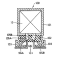
- FIG. 1 is a side view illustrating a schematic diagram of an electrolytic capacitor according to an embodiment of the present disclosure.
- FIG. 1 is an exploded perspective view illustrating a capacitor element according to an embodiment of the present disclosure.
- sugar alcohols are solids, they are dissolved in a solvent and used as a solution. Although it depends on the type of solvent, sugar alcohols tend to precipitate at room temperature, and the more sugar alcohol is used, the greater this tendency becomes. If sugar alcohol precipitates during the manufacturing process of an electrolytic capacitor, it becomes difficult to form a conductive polymer layer in good condition. Furthermore, if sugar alcohol precipitates inside a completed electrolytic capacitor, the characteristics of the electrolytic capacitor may deteriorate.
- the electrolytic capacitor according to the first aspect of the present disclosure includes at least a capacitor element.
- the capacitor element includes an anode foil having a dielectric layer, a cathode foil, a separator, and a conductive polymer layer.
- the separator is interposed between the anode foil and the cathode foil.
- the conductive polymer layer is interposed between the anode foil and the cathode foil and is in contact with the separator. It is preferable that the conductive polymer layer is in contact with each of the anode foil, the cathode foil, and the separator over a sufficiently large contact area. This allows a sufficient conductive path to be formed between the anode foil and the cathode foil by the conductive polymer layer, reducing the equivalent series resistance (ESR) of the electrolytic capacitor and improving reliability.
- ESR equivalent series resistance
- the conductive polymer layer contains a conductive polymer, a dopant, and a sugar alcohol.
- the sugar alcohol is at least one selected from the group consisting of xylitol and xylitol derivatives (hereinafter collectively referred to as a "xylitol compound"). Therefore, hereinafter, sugar alcohol may be referred to as a xylitol compound.
- xylitol compounds have a low melting point and excellent solubility in solvents. By using xylitol compounds, precipitation of sugar alcohols during the manufacturing process and in the completed electrolytic capacitor is sufficiently suppressed, even when a large amount of xylitol compounds is used.
- a large amount of xylitol compound is used when the ratio of the mass Ms of the sugar alcohol to the total mass Mp of the conductive polymer and dopant (Ms/Mp) is 1 or more and 40 or less.
- the ratio (Ms/Mp) is preferably 2 or more, more preferably 5 to 20, more preferably 7 to 20, and even more preferably 10 to 20.
- the xylitol derivative may be a compound in which some of the hydroxyl groups of xylitol are esterified, a compound in which some of the hydroxyl groups of xylitol are etherified, or a compound in which some of the hydroxyl groups of xylitol are anionized to form a salt.
- the chemical structure of the xylitol derivative is not limited to these.
- the molar mass of the xylitol derivative may be within a range of 0.9 to 2 times the molar mass of xylitol (152.15 g/mol).
- the chemical formula of the xylitol derivative may be based on the chemical formula of xylitol (C 5 H 7 (OH) 5 ), and may be, for example, C 5 H 7 (OH) 5-a X a (X is an atom or group other than an OH group, and 1 ⁇ a ⁇ 4).
- X may be a halogen atom, an OM group (M is an alkali metal atom), OR (R is a hydrocarbon group having 5 or less carbon atoms, and at least one hydrogen atom of the hydrocarbon group may be substituted with a hydrophilic group such as a hydroxyl group or a carboxyl group, a halogen atom, or the like.), etc. It is preferable that X satisfies 1 ⁇ a ⁇ 3 or 1 ⁇ a ⁇ 2.
- the mass content of the xylitol compound in the conductive polymer layer is preferably greater than the mass contents of all other components in the conductive polymer layer.
- the ratio (Ms/Mp) is 1 or greater, and may be 5 or greater, or 7 or greater, or 10 or greater.
- the mass content of the xylitol compound in the conductive polymer layer may be 50% by mass or more and 98% by mass or less, 60% by mass or more and 93% by mass or less, 50% by mass or more and 93% by mass or less, or 80% by mass or more and 93% by mass or less.
- the conductive polymer layer is preferably formed on at least one surface selected from the surface of the dielectric layer and the surface of the cathode foil, and may also be formed within the separator gap (i.e., the inner wall of the separator's constituent material surrounding the separator gap). This allows a stronger conductive path to be formed between the anode foil and the cathode foil by the conductive polymer layer.
- the conductive polymer layer is preferably formed on at least the surface of the dielectric layer of the anode foil, and is preferably formed on both the surface of the dielectric layer and the surface of the cathode foil, and further formed within the separator gap.
- the capacitor element may further include a liquid component contained in the voids within the capacitor element.
- the liquid component may be filled in at least a portion of the voids within the capacitor element.
- the electrolytic capacitor according to the present disclosure may be a solid electrolytic type capacitor or a solid-liquid hybrid type electrolytic capacitor.
- the liquid component preferably contains at least one selected from the group consisting of ethylene glycol, diethylene glycol, triethylene glycol, ethylene glycol condensates having a molecular weight of 250 or less, glycerin, ⁇ -butyrolactone, and sulfolane.
- the liquid component may be a solvent alone, or an electrolyte solution containing an electrolyte salt.
- the ratio (Ms/Mp) of the mass Ms of the sugar alcohol (xylitol compound) to the total mass Mp of the conductive polymer and the dopant can be determined, for example, by the following method.
- the cathode foil is separated from the capacitor element.
- a conductive polymer layer is attached to the cathode foil.
- water-soluble components are removed from the cathode foil to which the conductive polymer layer is attached.
- the water-soluble components include a xylitol compound. Since the conductive polymer and the dopant have different solubility in water from other water-soluble components, the conductive polymer and the dopant can be separated from the other components using water.
- the mass of the water-soluble components can be measured from the dry mass of the cathode foil before the water-soluble components are removed and the dry mass of the cathode foil after the water-soluble components are removed.
- the mass content of each component contained in the water-soluble components can be measured using various analytical methods, such as gas chromatography (GC) and gas chromatography-mass spectrometry (GC-MS).
- GC gas chromatography
- GC-MS gas chromatography-mass spectrometry
- the mass content of the conductive polymer layer contained in the sample can be measured by, for example, performing thermal analysis on the cathode foil after removing the water-soluble components using a differential scanning calorimeter.
- the above measurement results can be used to determine the ratio (Ms/Mp) in the conductive polymer layer of an electrolytic capacitor that does not contain liquid components.
- the cathode foil is separated from the capacitor element, and the liquid component is separated from the cathode foil.
- the cathode foil is immersed in an excess of a solvent (which may be ion-exchanged water) that has an affinity for the liquid component, and the solvent is thoroughly removed. After drying, the dried cathode foil does not contain any liquid component.
- a cathode foil having a conductive polymer layer that does not contain any liquid component attached thereto can be obtained.
- the water-soluble components are removed from the cathode foil to which the conductive polymer layer is attached, and the sample is dried and subjected to thermal analysis, for example, using a differential scanning calorimeter, to measure the mass content of the conductive polymer layer contained in the sample.
- the mass content of each component contained in the separated liquid and water-soluble components can be measured using various analytical methods, such as gas chromatography (GC) and gas chromatography-mass spectrometry (GC-MS).
- GC gas chromatography
- GC-MS gas chromatography-mass spectrometry
- liquid components can be separated and analyzed separately to determine the mass content of each component contained in the liquid components.
- the mass content of the solvent contained in the liquid component in the cathode foil can be determined from the mass content of the solvent and the separately determined mass content of each component contained in the liquid component.
- the above measurement results can be used to determine the ratio (Ms/Mp) in the conductive polymer layer of an electrolytic capacitor containing a liquid component.
- anode foil examples include metal foils containing at least one of valve metals such as titanium, tantalum, aluminum, and niobium.
- the anode foil may be a metal foil of a valve metal (e.g., aluminum foil).
- the anode foil may contain the valve metal in the form of an alloy containing the valve metal or a compound containing the valve metal.
- the thickness of the anode foil may be 15 ⁇ m or more and 300 ⁇ m or less.
- the surface of the anode foil may be roughened by etching or the like.
- a dielectric layer is formed on the surface of the anode foil.
- the dielectric layer may be formed by subjecting the anode foil to a chemical conversion treatment.
- the dielectric layer may contain an oxide of a valve metal (e.g., aluminum oxide).
- the dielectric layer may be formed of any dielectric other than an oxide of a valve metal as long as it functions as a dielectric.
- a conductive polymer layer does not need to be formed on the end surface of the anode foil.
- a dielectric layer is formed on the end surface of the anode foil.
- the cathode foil is not particularly limited as long as it has a function as a cathode.
- Examples of the cathode foil include metal foil (e.g., aluminum foil).
- the type of metal is not particularly limited, and may be a valve metal or an alloy containing a valve metal.
- the thickness of the cathode foil may be 15 ⁇ m or more and 300 ⁇ m or less.
- the surface of the cathode foil may be roughened or chemically treated as necessary.
- the cathode foil may include a conductive coating layer.
- the coating layer may include carbon and at least one metal having a lower ionization tendency than the valve metal. This makes it easier to improve the acid resistance of the metal foil.
- the coating layer may include at least one metal selected from the group consisting of carbon, nickel, titanium, tantalum, and zirconium. In particular, the coating layer may include nickel and/or titanium, which are low in cost and resistance.
- the thickness of the coating layer may be 5 nm or more, or 10 nm or more, or may be 200 nm or less.
- the coating layer may be formed by vapor deposition or sputtering of the above-mentioned metal on the metal foil.
- the coating layer may be formed by vapor deposition of a conductive carbon material on the metal foil or by applying a carbon paste containing a conductive carbon material. Examples of conductive carbon materials include graphite, hard carbon, soft carbon, carbon black, etc.
- a porous sheet can be used for the separator.
- the porous sheet include woven fabric, nonwoven fabric, and microporous membrane.
- the thickness of the separator is not particularly limited and may be in the range of 10 ⁇ m to 300 ⁇ m.
- the material of the separator include cellulose, polyethylene terephthalate, polybutylene terephthalate, polyphenylene sulfide, vinylon, nylon, aromatic polyamide, polyimide, polyamideimide, polyetherimide, rayon, glass, and the like.
- the exterior body includes a case and/or a sealing resin.
- the sealing resin may include a thermosetting resin.
- the thermosetting resin include an epoxy resin, a phenolic resin, a silicone resin, a melamine resin, a urea resin, an alkyd resin, a polyurethane, a polyimide, an unsaturated polyester, and the like.
- the sealing resin may include a filler, a curing agent, a polymerization initiator, and/or a catalyst, and the like.
- FIG. 1 is a cross-sectional view showing an example of an electrolytic capacitor 100 according to this embodiment.
- FIG. 2 is a schematic diagram showing an exploded view of a portion of a capacitor element 10 included in the electrolytic capacitor 100.
- the electrolytic capacitor 100 comprises a capacitor element 10, a bottomed case 101 that houses the capacitor element 10, a sealing member 102 that closes the opening of the bottomed case 101, a seat plate 103 that covers the sealing member 102, lead wires 104A, 104B that extend from the sealing member 102 and pass through the seat plate 103, and lead tabs 105A, 105B that connect the lead wires to the electrodes of the capacitor element 10.
- the area near the open end of the bottomed case 101 is drawn inward, and the open end is curled so as to be crimped to the sealing member 102.
- Capacitor element 10 is, for example, a wound body as shown in FIG. 1.
- the wound body includes anode foil 11 connected to lead tab 105A, cathode foil 12 connected to lead tab 105B, and separator 13.
- Capacitor element 10 (wound body) includes a conductive polymer layer (not shown).
- the anode foil 11 and the cathode foil 12 are wound with a separator 13 between them.
- the outermost circumference of the wound body is fixed with a stop tape 14. Note that Figure 1 shows the wound body in a partially unfolded state before the outermost circumference is fixed.
- An electrolytic capacitor may have at least one capacitor element, but may also have multiple capacitor elements.
- the number of capacitor elements included in an electrolytic capacitor may be determined according to the application.
- the electrolytic capacitor according to the present disclosure can be manufactured by the manufacturing method (I) according to the second aspect of the present disclosure or the manufacturing method (II) according to the third aspect of the present disclosure, which are described below.
- the electrolytic capacitor may also be manufactured by a method other than the manufacturing methods (I) and (II).
- the second aspect of the present disclosure relates to a method (I) for producing an electrolytic capacitor, which includes the steps of (a) preparing an anode foil having a dielectric layer, a cathode foil, and a separator, (b) applying a coating liquid containing a conductive polymer, a dopant, and a liquid medium to at least one surface selected from the surface of the dielectric layer and the surface of the cathode foil and into the voids of the separator, (c) forming a conductive polymer layer on at least one surface and in the voids of the separator by removing at least a part of the liquid medium from the coating liquid, (d) forming a capacitor element including a conductive polymer layer by disposing a separator between the anode foil and the cathode foil, and (e) impregnating the capacitor element with a solution containing a xylitol compound to cause the conductive polymer layer to contain the
- Step (a)> The process of preparing the anode foil, the cathode foil, and the separator having the dielectric layer is not particularly limited.
- the materials of the anode foil, the cathode foil, and the separator are also not particularly limited. The materials already described may be used for the anode foil, the cathode foil, and the separator.
- the coating liquid may be applied to the surface of the dielectric layer and the separator, or the coating liquid may be applied to the surface of the cathode foil and the separator. Alternatively, the coating liquid may be applied to the surface of the dielectric layer, the surface of the cathode foil, and the separator. If necessary, the coating liquid is applied onto the dielectric layers formed on both sides of the anode foil, and the coating liquid is applied onto both sides of the cathode foil. A conductive polymer layer is formed at the location where the coating liquid is applied.
- the coating liquid may be performed by a known method.
- the coating liquid may be sprayed or the object to be coated may be immersed in the coating liquid.
- Examples of the method using a coater include gravure coating and die coating.
- the coating liquid is applied to a transfer member such as a gravure roll, and after removing excess coating liquid from the transfer member, the coating liquid applied to the transfer member is transferred to each of the anode foil, cathode foil, and separator, so that a layer of coating liquid of uniform thickness can be applied to each of the anode foil, cathode foil, and separator.
- the method of applying the coating liquid to the separator includes a method of impregnating the separator with the coating liquid.
- the coating liquid applied to the separator permeates the inside of the separator, and a conductive polymer layer can be formed over the entire thickness of the separator.
- the viscosity of the coating liquid may be, for example, 10 mPa ⁇ s or more (or 100 mPa ⁇ s or more) and 200 mPa ⁇ s or less.
- the coating liquid can be easily applied to the anode foil, cathode foil, and separator, and can easily be impregnated into the separator.
- the viscosity of the coating liquid can be measured at room temperature (20°C) using a vibration viscometer (for example, VM-100A, manufactured by Sekonic Corporation).
- the dopant may be doped into the conductive polymer.
- the dopant may be an anion having a negative charge
- the conductive polymer may be a cation having a positive charge.
- the ionized dopant and the conductive polymer may interact with each other through Coulomb force.
- the conductive polymer doped with the dopant may be dispersed in the coating liquid in the form of particles.
- the liquid medium preferably contains water.
- the liquid medium may contain an organic compound that does not boil at 100°C under 1 atmosphere (hereinafter also referred to as "organic compound (C)").
- organic compound (C) one type of compound may be used, or multiple types of compounds may be used.
- Organic compound (C) can be read as "at least one type of organic compound.”
- boiling point means the boiling point at 1 atmosphere.
- organic compound (C) include organic compounds having a boiling point higher than 100°C.
- the boiling point may be 110°C or higher, 150°C or higher, or 200°C or higher, or 400°C or lower, 300°C or lower, 250°C or lower, or 200°C or lower.
- the boiling point may be in the range of 110°C to 400°C (e.g., 150°C to 350°C).
- the water content in the coating liquid is preferably 40% by mass or more (e.g., 50% by mass or more), and after the conductive polymer layer is formed, a solution containing a xylitol compound or a liquid component (e.g., an electrolyte solution) can easily penetrate into the conductive polymer layer.
- a solution containing a xylitol compound or a liquid component e.g., an electrolyte solution
- the content of the organic compound (C) in the coating liquid may be 0% by mass or more and 10% by mass or less.
- organic compound (C) is a compound that does not boil at 100°C at 1 atmosphere. Therefore, by heating the coating liquid at a temperature at which organic compound (C) does not boil or decompose and at a temperature of 100°C or higher, water can be removed from the coating liquid while organic compound (C) remains. As a result, organic compound (C) remains in the formed conductive polymer layer. In that case, a solution or liquid component (e.g., electrolyte) containing the xylitol compound can easily penetrate the conductive polymer layer thereafter.
- a solution or liquid component e.g., electrolyte
- the method for removing at least a part of the liquid medium from the coating liquid is not limited.
- the liquid medium may be removed by heating and/or reducing pressure, and it is preferable to at least heat the liquid medium.
- the heating temperature is preferably a temperature at which the organic compound (C) does not boil or decompose.
- the heating temperature may be 100°C or higher, 120°C or higher, or 140°C or higher, and may be 200°C or lower, or 160°C or lower.
- the heating temperature may be in the range of 100°C to 200°C. There is no particular limit to the heating time, as long as it is a time that allows at least a part of the liquid medium to be appropriately removed. An example heating time is in the range of 5 to 60 minutes.
- heating may be performed two or more times within a specified temperature range (for example, a temperature range of 100°C to 200°C).
- a coating liquid may be applied to one side and then heated, and then a coating liquid may be applied to the other side and then heated.
- a similar method can be applied when forming a conductive polymer layer on both sides of a cathode foil.
- step (d) a conductive polymer layer is formed on at least one of the anode foil and the cathode foil and a separator, and then the separator is disposed between the anode foil and the cathode foil to form a capacitor element including the conductive polymer layer.
- This step is also a step in which the anode foil and the cathode foil are laminated with the separator interposed therebetween.
- the capacitor element may be referred to as a "laminate.”
- the capacitor element may be formed by a known method.
- the capacitor element may be a wound body.
- the wound body is formed by winding an anode foil, a cathode foil, and a separator such that the separator is disposed between the anode foil and the cathode foil.
- the anode foil, the cathode foil, and the separator are stacked in the radial direction of the wound body.
- the capacitor element may be formed by stacking flat anode foils, flat cathode foils, and flat separators in one direction.
- a laminate capacitor element may be formed by stacking multiple anode foils, multiple cathode foils, and multiple separators in one direction.
- the anode foils and cathode foils are arranged alternately, and the separators are arranged between the anode and cathode foils.
- step (e) the capacitor element is impregnated with a solution containing a xylitol compound (hereinafter also referred to as "xylitol solution").
- xylitol solution a solution containing a xylitol compound
- the solvent of the xylitol solution preferably contains at least water. 80% by mass or more, and even 90% by mass or more (preferably 100%) of the solvent of the xylitol solution may be water.
- the solvent of the xylitol solution may also contain an organic solvent.
- the organic solvent ethylene glycol, sulfolane, and ⁇ -butyrolactone can be used.
- the mass content of the xylitol compound in the xylitol solution is preferably 10% by mass to 75% by mass, and may be 15% by mass to 60% by mass.
- the capacitor element may be impregnated with the xylitol compound by immersing at least a portion of the capacitor element in the xylitol solution.
- the step of immersing at least a portion of the capacitor element in the xylitol solution and the step of removing at least a portion of the solvent may be performed multiple times.
- the xylitol solution may be heated to 40°C to 90°C.
- a step of impregnating the voids in the capacitor element with a liquid component may be further carried out.
- a liquid component may be a solvent only, or an electrolyte solution containing an electrolyte salt.
- the liquid component may be impregnated into the capacitor element by immersing at least a portion of the capacitor element in the liquid component.
- the ratio (Ms/Mp) of the mass Ms of the xylitol compound to the total mass Mp of the conductive polymer and the dopant can be easily controlled to 1 or more and 40 or less, and further 5 or more and 20 or less.
- An example of a typical electrolytic capacitor includes a wound body of an anode foil, a separator, and a cathode foil.
- Such an electrolytic capacitor includes a conductive polymer layer disposed in the wound body.
- the conductive polymer layer is formed by impregnating the wound body with a dispersion liquid containing a conductive polymer.
- the dispersion containing the conductive polymer has a high viscosity, even if the dispersion is impregnated into the wound body, it may not be possible to form a sufficient conductive polymer layer inside the wound body. Insufficient formation of the conductive polymer layer can cause a decrease in initial capacity, an increase in equivalent series resistance (ESR), and a decrease in reliability. Furthermore, because sugar alcohols are solids, solutions in which sugar alcohols are dissolved in solvents have a high viscosity. If sugar alcohols are added to the dispersion containing the conductive polymer, it becomes even more difficult to form a sufficient conductive polymer layer inside the wound body.
- the manufacturing method of an electrolytic capacitor (I) includes steps (b) and (c), so that the coating liquid is applied to at least one surface selected from the surface of the dielectric layer of the anode foil and the surface of the cathode foil, and the coating liquid is also applied into the gaps of the separator.
- the coating liquid can have a high viscosity because it contains a conductive polymer and a dopant.
- a coating device coater
- a sufficient amount of conductive polymer layer can be formed in the capacitor element.
- the manufacturing method of an electrolytic capacitor (I) can form a sufficient amount of conductive polymer layer in the gaps of the separator (more precisely, the inner wall formed of the separator material to surround the gaps) when the coating liquid is applied to the surface of the separator, for example, using a coating device (coater).
- the xylitol compound used in step (e) of the manufacturing method (I) of the electrolytic capacitor has a low melting point among sugar alcohols and has excellent solubility in solvents, so a sufficient amount of sugar alcohol or xylitol compound can be contained inside the conductive polymer layer. Therefore, the xylitol compound easily penetrates into the conductive polymer layer, and the xylitol compound increases the adhesive strength between the conductive polymer layers formed on each component. Therefore, a strong conductive path can be formed between the anode foil and the cathode foil by the conductive polymer layer.
- the total mass Mp of the conductive polymer and dopant and the mass Ms of the xylitol compound in the conductive polymer layer can be controlled by controlling the concentrations of the conductive polymer and dopant in the coating liquid and the concentration of the xylitol compound in the solution containing the xylitol compound.
- a conductive polymer layer can be formed as a combination of a first conductive polymer layer formed on the surface of the dielectric layer of the anode foil and/or the surface of the cathode foil, and a second conductive polymer layer formed in the voids of the separator.
- the first conductive polymer layer and the second conductive polymer layer may be composed of the same conductive polymer or may contain different conductive polymers.
- the first conductive polymer layer and the second conductive polymer layer may contain the same dopant or may contain different dopants.
- the first conductive polymer layer formed on the anode foil (on the dielectric layer), the first conductive polymer layer formed on the cathode foil, and the second conductive polymer layer may be composed of the same conductive polymer or may contain different conductive polymers.
- the first conductive polymer layer formed on the anode foil (on the dielectric layer), the first conductive polymer layer formed on the cathode foil, and the second conductive polymer layer may contain the same dopant or may contain different dopants.
- the first conductive polymer layer is formed on the surface of the anode foil (or cathode foil)
- the first conductive polymer layer is preferably formed on the entire surface of the electrode foil (anode foil, cathode foil) that contributes to the capacitance of the capacitor element.
- the area on which the second conductive polymer layer is formed on the separator is preferably 80% or more (e.g., 90% or more) of the separator area, and may be formed on the entire separator.
- the surface area of the electrode foil refers to the area that does not take into account the unevenness of the surface and can be calculated from the outer shape of the electrode foil.
- the surface area on which the first conductive polymer is formed is the sum of the areas of both sides.
- the mass of the first conductive polymer layer per unit area may be 0.01 mg/ cm2 or more, or 0.02 mg/ cm2 or more, and may be 0.5 mg/cm2 or less , or 0.3 mg/ cm2 or less. By setting the mass to 0.1 mg/ cm2 or more, the conductive polymer layer can be formed more uniformly.
- the above-mentioned mass per unit area is the mass of the layer formed on one side of the electrode foil.
- the mass of the second conductive polymer layer per unit area may be 0.02 mg/ cm2 or more, or 0.05 mg/ cm2 or more, and may be 2.0 mg/cm2 or less , or 1.0 mg/ cm2 or less. By setting the mass to 0.3 mg/ cm2 or more, the conductive polymer layer can be formed more uniformly.
- the mass of the conductive polymer layer per unit area can be determined by the following method. First, five samples are prepared by cutting out a specified area from the member (electrode foil or separator) before the conductive polymer layer is formed, and the masses of the five samples are measured. In addition, five samples are prepared by cutting out the member (electrode foil or separator) on which the conductive polymer layer is formed, and the masses of the samples are measured. The mass of the conductive polymer layer per unit area is determined using the specified area and the difference between the total mass of the five samples after the conductive polymer layer is formed and the total mass of the five samples before the conductive polymer layer is formed.
- manufacturing method (I) may include steps other than the above steps as necessary.
- the third aspect of the present disclosure relates to a method for producing an electrolytic capacitor (II), which includes the steps of: (a) preparing an anode foil having a dielectric layer, a cathode foil, and a separator; (b) applying a coating liquid containing a conductive polymer, a dopant, a xylitol compound, and a liquid medium to at least one surface selected from the surface of the dielectric layer and the surface of the cathode foil and into the voids of the separator; (c) forming a conductive polymer layer on at least one surface and in the voids of the separator by removing at least a part of the liquid medium from the coating liquid; and (d) forming a capacitor element including the conductive polymer layer by disposing a separator between the anode foil and the cathode foil, in this order.
- manufacturing method (II) differs from manufacturing method (I) in that a xylitol compound is contained in the coating liquid, and therefore there is no need to carry out the step of impregnating the capacitor element with a solution containing a xylitol compound (step (d) of manufacturing method (I)).
- step (d) of manufacturing method (I) may be carried out in manufacturing method (II).
- the ratio (Ms/Mp) of the mass Ms of the xylitol compound to the total mass Mp of the conductive polymer and the dopant can be easily controlled to 1 or more and 40 or less, and further 5 or more and 20 or less.
- a coating liquid is applied to at least one surface selected from the surface of the dielectric layer of the anode foil and the surface of the cathode foil, and the coating liquid is also applied into the voids of the separator.
- the coating liquid contains a conductive polymer and a dopant, and further contains a xylitol compound, so it can be highly viscous.
- a coating device coater
- a sufficient amount of conductive polymer layer can be formed in the capacitor element, and the conductive polymer layer can contain the xylitol compound at any mass content.
- the coating liquid when applied to the surface of the separator, for example, using a coating device (coater), a sufficient amount of conductive polymer layer can be formed in the voids of the separator, and the conductive polymer layer can contain the xylitol compound at any mass content.
- a coating device coater
- the total mass Mp of the conductive polymer and dopant in the conductive polymer layer and the mass Ms of the xylitol compound can be controlled by controlling the concentrations of these components in the coating liquid. Therefore, any ratio (Ms/Mp) can be achieved.
- step (II) if a step of impregnating the voids in the capacitor element with a liquid component (solvent only, or an electrolyte solution containing an electrolyte salt) is further carried out after step (d), a solid-liquid hybrid electrolytic capacitor can be obtained.
- a liquid component solvent only, or an electrolyte solution containing an electrolyte salt
- a conductive polymer layer can be formed as a combination of a first conductive polymer layer formed on the surface of the dielectric layer of the anode foil and/or the surface of the cathode foil, and a second conductive polymer layer formed in the voids of the separator.
- a mixed region in which a part of the first conductive polymer layer and a part of the second conductive polymer layer are mixed can be formed at the boundary between the first conductive polymer layer and the second conductive polymer layer.
- the coating liquid includes a conductive polymer, a dopant, and a liquid medium, and may include a xylitol compound.
- the liquid medium preferably includes water, and further includes an organic compound (C). If necessary, the coating liquid may include other components.
- the organic compound (C) an organic compound that is easily soluble in water can be preferably used.
- the organic compound (C) may be a compound that is miscible with water.
- the coating liquid may contain sugar alcohols other than xylitol compounds. However, it is preferable that the majority of the sugar alcohols contained in the coating liquid are xylitol compounds. It is preferable that 80% by mass or more (even more preferably 90% by mass or more) of the sugar alcohols contained in the coating liquid are xylitol compounds. Examples of sugar alcohols other than xylitol compounds include mannitol, sorbitol, erythritol, and pentaerythritol.
- Examples of the organic compound (C) include compounds used as organic solvents.
- Examples of the organic compound (C) include polyhydric alcohols (excluding sugar alcohols) having two or more hydroxyl groups.
- Water in which the organic compound (C) is dissolved can be used as a dispersion medium for the conductive polymer.
- the coating liquid is a dispersion liquid in which particles of a conductive polymer doped with a dopant are dispersed, and the dispersion medium can be water in which the organic compound (C) and/or a xylitol compound is dissolved.
- Examples of the organic compound (C) include polyhydric alcohols (excluding sugar alcohols), sulfolane, ⁇ -butyrolactone, and boric acid esters.
- the organic compound (C) may include at least one selected from the group consisting of polyhydric alcohols, sulfolane, ⁇ -butyrolactone, and boric acid esters, or may be at least one of the above.
- polyhydric alcohols examples include glycols and glycerins.
- glycols include ethylene glycol, diethylene glycol, triethylene glycol, polyalkylene glycols (e.g., polyethylene glycol), polyoxyethylene polyoxypropylene glycol (ethylene oxide-propylene oxide copolymer), and the like.
- polyalkylene glycols e.g., polyethylene glycol
- polyoxyethylene polyoxypropylene glycol ethylene oxide-propylene oxide copolymer
- glycerins examples include glycerin and polyglycerin.
- Examples of conductive polymers include polypyrrole, polythiophene, polyfuran, polyaniline, polyacetylene, and derivatives thereof.
- the derivatives include polymers having polypyrrole, polythiophene, polyfuran, polyaniline, and polyacetylene as the basic skeleton.
- a derivative of polythiophene includes poly(3,4-ethylenedioxythiophene).
- These conductive polymers may be used alone or in combination.
- the conductive polymer may also be a copolymer of two or more monomers.
- the weight-average molecular weight of the conductive polymer is not particularly limited and may be in the range of 1,000 to 100,000, for example.
- a preferred example of a conductive polymer is poly(3,4-ethylenedioxythiophene) (PEDOT).
- the conductive polymer is doped with a dopant. From the viewpoint of suppressing dedoping from the conductive polymer, it is preferable to use a polymer dopant as the dopant.
- polymer dopants include polyvinyl sulfonic acid, polystyrene sulfonic acid, polyallyl sulfonic acid, polyacryl sulfonic acid, polymethacryl sulfonic acid, poly(2-acrylamido-2-methylpropane sulfonic acid), polyisoprene sulfonic acid, polyacrylic acid, and the like. These may be used alone or in combination of two or more. At least a portion of these may be added in the form of a salt.
- a preferred example of the dopant is polystyrene sulfonic acid (PSS).
- the dopant may be a dopant containing an acidic group, or may be a polymer dopant containing an acidic group.
- acidic groups include sulfonic acid groups and carboxyl groups.
- a polymer dopant containing an acidic group is a polymer in which at least some of the constituent units contain an acidic group. Examples of such polymer dopants include the polymer dopants described above.
- the weight-average molecular weight of the dopant is not particularly limited. From the viewpoint of facilitating the formation of a homogeneous conductive polymer layer, the weight-average molecular weight of the dopant may be in the range of 1,000 to 100,000.
- the dopant may be polystyrenesulfonic acid, and the conductive polymer may be poly(3,4-ethylenedioxythiophene). That is, the conductive polymer doped with the dopant may be poly(3,4-ethylenedioxythiophene) doped with polystyrenesulfonic acid.
- the pH of the coating liquid is preferably less than 7.0 in order to suppress dedoping of the dopant, and may be 6.0 or less or 5.0 or less.
- the pH of the coating liquid may be 1.0 or more, or 2.0 or more.
- the conductive polymer doped with the dopant may be present in the coating liquid in the form of particles.
- the mode of particle size may be 10 nm or more, or 20 nm or more, or may be 1000 nm or less, 500 nm or less, 200 nm or less, or 100 nm or less.
- the volume-based particle size distribution can be determined using a laser diffraction/scattering type particle size distribution measuring device.
- the mode of particle size of the conductive polymer particles doped with the dopant may be in the range of 20 nm to 200 nm (e.g., in the range of 20 nm to 100 nm).
- the volume-based proportion of particles with particle sizes in the range of 20 nm to 100 nm may be 90% or more of the total.
- the water content in the coating liquid may be 40% by mass or more, 50% by mass or more, 70% by mass or more, 73% by mass or more, 78% by mass or more, 80% by mass or more, 88% by mass or more, 90% by mass or more, or 95% by mass or more.
- the content may be 98% by mass or less, 95% by mass or less, 90% by mass or less, or 80% by mass or less.
- the content may be in the range of 40 to 98% by mass or more, 50 to 98% by mass, 80 to 98% by mass, or 70 to 98% by mass. In any of these ranges, the upper limit may be replaced by 95% by mass, 90% by mass, or 80% by mass.
- the content of the xylitol compound and the organic compound (C) in the coating liquid may be 0% by mass or more, 1.0% by mass or more, 3.0% by mass or more, 5.0% by mass or more, or 10% by mass or more.
- the content may be 59.5% by mass or less, 45% by mass or less, 30% by mass or less, 25% by mass or less, 20% by mass or less, 15% by mass or less, or 10% by mass or less.
- the content may be in the range of 1 to 59.5% by mass, the range of 3 to 59.5% by mass, or the range of 5 to 59.5% by mass. In any of these ranges, the upper limit may be replaced by 45% by mass, 30% by mass, 25% by mass, 20% by mass, 15% by mass, or 10% by mass.
- the total mass content of the conductive polymer and dopant in the coating liquid may be 0.5 mass% or more, or 1.0 mass% or more, and may be 4.0 mass% or less, 3.0 mass% or less, or 2.0 mass% or less.
- the content may be in the range of 0.5 to 4.0 mass%, or in the range of 1.0 to 4.0 mass%. In either of these ranges, the upper limit may be 3.0 mass% or 2.0 mass%.
- the content is preferably in the range of 1.0 to 3.0%.
- the mass of the dopant contained in the coating liquid there are no particular limitations on the mass of the dopant contained in the coating liquid, and it may be in the range of 0.1 to 5 times (e.g., 0.5 to 3 times) the mass of the conductive polymer contained in the coating liquid.
- the mass content of the xylitol compound in the coating liquid is preferably 1 to 12 times, and more preferably 7 to 12 times, the combined mass content of the conductive polymer and dopant in the coating liquid.
- the content is preferably in the range of 1.0 to 3.0%, in terms of excellent physical properties of the coating liquid and its stability over time, and a good balance between the ESR of the electrolytic capacitor and cost.
- the ratio of water content: total content of xylitol compound and organic compound (C): total content of conductive polymer and dopant may be (40-98): (1.0-59.5): (0.5-4.0), or may be (69.5-98): (1.0-30): (0.5-4.0).
- the above water content, the total content of the xylitol compound and the organic compound (C), and the total content of the conductive polymer and the dopant can be combined in any way as long as no contradiction occurs.
- One example of the coating liquid may satisfy one, two, three, or four conditions selected from the following conditions (1) to (5), or may satisfy all of the conditions.
- the water content is in the range of 50 to 98 mass% (e.g., in the range of 73 to 95 mass%)
- the total content of the xylitol compound and the organic compound (C) is in the range of 3 to 30 mass% (e.g., in the range of 5 to 25 mass%)
- the total content of the conductive polymer and the dopant is in the range of 0.5 to 4.0 mass% (e.g., in the range of 1.0 to 3.0 mass%).
- the mass content of the xylitol compound in the coating liquid is 1 to 45 times, and further 7 to 20 times, the total mass content of the conductive polymer and the dopant in the coating liquid.
- the organic compound (C) is a glycol (e.g., ethylene glycol).
- the conductive polymer component includes poly(3,4-ethylenedioxythiophene) and polystyrenesulfonic acid.
- the conductive polymer component may be composed of poly(3,4-ethylenedioxythiophene) and polystyrenesulfonic acid.
- the pH of the coating liquid is in the range of 1.0 to 6.0 (for example, in the range of 2.0 to 5.0).
- the conductive polymer doped with a dopant is present in the coating liquid in the form of particles, and in the volume-based particle size distribution of the particles, the mode of particle size is in the range of 20 nm to 1000 nm (e.g., 20 nm to 200 nm or 20 nm to 100 nm).
- the proportion (volume-based) of particles having a particle size in the range of 20 nm to 1000 nm (e.g., 20 nm to 200 nm or 20 nm to 100 nm) of the total particles may be 90% or more.
- liquid component examples include a solvent and an electrolyte.
- a solvent in which a solute is dissolved can be used as the electrolyte.
- the liquid component may be a component that is liquid at room temperature (25° C.) or a component that is liquid at the temperature when the electrolytic capacitor is used.
- the solvent used for the liquid component may be an organic solvent, an ionic liquid, or a protic solvent.
- non-aqueous solvents include polyhydric alcohols such as ethylene glycol and propylene glycol, cyclic sulfones such as sulfolane (SL), lactones such as ⁇ -butyrolactone ( ⁇ BL), amides such as N-methylacetamide, N,N-dimethylformamide, and N-methyl-2-pyrrolidone, esters such as methyl acetate, carbonate compounds such as propylene carbonate, ethers such as 1,4-dioxane, ketones such as methyl ethyl ketone, and formaldehyde.
- polyhydric alcohols such as ethylene glycol and propylene glycol
- cyclic sulfones such as sulfolane (SL)
- lactones such as ⁇ -butyrolactone ( ⁇ BL)
- amides such as N-methylace
- a polymer solvent may be used as the solvent.
- polymer solvents include polyalkylene glycol, derivatives of polyalkylene glycol, and compounds in which at least one hydroxyl group in a polyhydric alcohol is replaced with polyalkylene glycol (including derivatives).
- examples of polymer solvents include polyethylene glycol (PEG), polyethylene glycol glyceryl ether, polyethylene glycol diglyceryl ether, polyethylene glycol sorbitol ether, polypropylene glycol, polypropylene glycol glyceryl ether, polypropylene glycol diglyceryl ether, polypropylene glycol sorbitol ether, and polybutylene glycol.
- polymer solvents further include ethylene glycol-propylene glycol copolymers, ethylene glycol-butylene glycol copolymers, and propylene glycol-butylene glycol copolymers.
- the non-aqueous solvent may be used alone or in a mixture of two or more.
- the liquid component may contain a xylitol compound as a solute.
- xylitol compounds have a low melting point and excellent solubility in solvents.
- a case where a large amount of xylitol compound is used means that the content of the xylitol compound in the liquid component is, for example, 4% by mass or more and 70% by mass or less.
- the xylitol compound acts on the conductive polymer layer, further increasing the contact area between the conductive polymer layer and the anode foil, cathode foil, and separator, making it easier for a sufficient conductive path to be formed by the conductive polymer layer between the anode foil and cathode foil.
- the mass content of the xylitol compound in the liquid component is preferably 5 mass% or more, more preferably 7.5 mass% or more, and even more preferably 10 mass% or more or 15 mass% or more.
- the mass content of xylitol compounds in the liquid component is preferably 50% by mass or less, more preferably 40% by mass or less, and even more preferably 30% by mass or less.
- the solute may further include at least one selected from the group consisting of acids, bases, and electrolyte salts.
- the total mass content of all solutes in the liquid component is preferably 70 mass% or less, and more preferably 50 mass% or less.
- polycarboxylic acids and monocarboxylic acids can be used.
- the polycarboxylic acids include aliphatic polycarboxylic acids (saturated polycarboxylic acids such as oxalic acid, malonic acid, succinic acid, glutaric acid, adipic acid, pimelic acid, suberic acid, azelaic acid, sebacic acid, 1,6-decanedicarboxylic acid, 5,6-decanedicarboxylic acid; unsaturated polycarboxylic acids such as maleic acid, fumaric acid, and itanoic acid), aromatic polycarboxylic acids (phthalic acid, isophthalic acid, terephthalic acid, trimellitic acid, and pyromellitic acid), and alicyclic polycarboxylic acids (cyclohexane-1,2-dicarboxylic acid, cyclohexene-1,2-dicarboxylic acid, etc.).
- saturated polycarboxylic acids such as oxalic
- Examples of the monocarboxylic acids include aliphatic monocarboxylic acids (1 to 30 carbon atoms) ([saturated monocarboxylic acids, such as formic acid, acetic acid, propionic acid, butyric acid, isobutyric acid, valeric acid, caproic acid, enanthic acid, caprylic acid, pelargonic acid, lauric acid, myristic acid, stearic acid, behenic acid]; [unsaturated monocarboxylic acids, such as acrylic acid, methacrylic acid, oleic acid]), aromatic monocarboxylic acids (such as benzoic acid, cinnamic acid, naphthoic acid), and oxycarboxylic acids (such as salicylic acid, mandelic acid, resorcylic acid).
- saturated monocarboxylic acids such as formic acid, acetic acid, propionic acid, butyric acid, isobutyric acid, valeric acid, caproic acid
- maleic acid, phthalic acid, benzoic acid, pyromellitic acid, and resorcylic acid are thermally stable and are preferably used.
- Inorganic acids may be used as the acid component.
- inorganic acids include phosphoric acid, phosphorous acid, hypophosphorous acid, alkyl phosphate esters, boric acid, boric fluoride, tetrafluoroboric acid, hexafluorophosphoric acid, benzenesulfonic acid, and naphthalenesulfonic acid.
- composite compounds of organic acids and inorganic acids may be used as the acid component. Examples of such composite compounds include borodiglycolic acid, borodioxalic acid, and borodisalicylic acid.
- the base component may be a compound having an alkyl-substituted amidine group, such as an imidazole compound, a benzimidazole compound, or an alicyclic amidine compound (pyrimidine compound, imidazoline compound).
- an imidazole compound such as an imidazole compound, a benzimidazole compound, or an alicyclic amidine compound (pyrimidine compound, imidazoline compound).
- 1,8-diazabicyclo[5,4,0]undecene-7, 1,5-diazabicyclo[4,3,0]nonene-5 1,2-dimethylimidazolinium, 1,2,4-trimethylimidazoline, 1-methyl-2-ethyl-imidazoline, 1,4-dimethyl-2-ethylimidazoline, 1-methyl-2-heptyl imidazoline, 1-methyl-2-(3'heptyl)imidazoline, 1-methyl-2-dodecyl imidazoline, 1,2-di
- the base component may be a quaternary salt of a compound having an alkyl-substituted amidine group.
- base components include imidazole compounds, benzimidazole compounds, and alicyclic amidine compounds (pyrimidine compounds, imidazoline compounds) that are quaternized with an alkyl group or arylalkyl group having 1 to 11 carbon atoms.
- Tertiary amines may be used as the base component.
- tertiary amines include trialkylamines (trimethylamine, dimethylethylamine, methyldiethylamine, triethylamine, dimethyl-n-propylamine, dimethylisopropylamine, methylethyl-n-propylamine, methylethylisopropylamine, diethyl-n-propylamine, diethylisopropylamine, tri-n-propylamine, triisopropylamine, tri-n-butylamine, tri-tert-butylamine, etc.), and phenyl group-containing amines (dimethylphenylamine, methylethylphenylamine, diethylphenylamine, etc.).
- trialkylamines are preferred in terms of increasing electrical conductivity, and it is more preferred to include at least one selected from the group consisting of trimethylamine, dimethylethylamine, methyldiethylamine, and triethylamine.
- Secondary amines such as dialkylamines, primary amines such as monoalkylamines, and ammonia may also be used as the base component.
- the liquid component may contain a salt of an acid component and a base component.
- the salt may be an inorganic salt and/or an organic salt.
- An organic salt is a salt in which at least one of the anion and the cation contains an organic substance. Examples of organic salts that may be used include trimethylamine maleate, triethylamine borodisalicylate, ethyldimethylamine phthalate, mono 1,2,3,4-tetramethylimidazolinium phthalate, and mono 1,3-dimethyl-2-ethylimidazolinium phthalate.
- the pH of the liquid component (L) may be less than 7.0 or less than 5.0, or may be greater than 1.0, or greater than 2.0.
- the pH may be greater than 1.0 and less than 7.0 (e.g., in the range of 2.0 to 5.0).
- the liquid component preferably contains a protic solvent.
- a protic solvent By using a protic solvent, it is possible to particularly swell the conductive polymer layer.
- the liquid component may contain a solvent other than the protic solvent.
- the protic solvent may include at least one selected from the group consisting of glycols, glycerin, polyglycerin, and sugar alcohols, or may be at least one of the above.
- the protic solvent may be composed of only one type of compound, or may include multiple types of compounds.
- an anode foil having a dielectric layer A cathode foil; a separator interposed between the anode foil and the cathode foil; a conductive polymer layer interposed between the anode foil and the cathode foil and in contact with the separator; the conductive polymer layer includes a conductive polymer, a dopant, and a sugar alcohol;
- the sugar alcohol is at least one selected from the group consisting of xylitol and xylitol derivatives, an electrolytic capacitor, wherein in the conductive polymer layer, a ratio (Ms/Mp) of a mass Ms of the sugar alcohol to a total mass Mp of the conductive polymer and the dopant is 1 or more and 40 or less.
- liquid component includes at least one selected from the group consisting of ethylene glycol, diethylene glycol, triethylene glycol, an ethylene glycol condensate having a molecular weight of 250 or less, glycerin, ⁇ -butyrolactone, and sulfolane.
- the conductive polymer layer includes a first conductive polymer layer formed on the at least one surface and a second conductive polymer layer formed in voids of the separator; 10.
- the conductive polymer layer includes a first conductive polymer layer formed on the at least one surface and a second conductive polymer layer formed in voids of the separator; 13.
- Example The present disclosure will be described in more detail below based on examples, but the present disclosure is not limited to the examples.
- a plurality of electrolytic capacitors were produced and evaluated by the following method.
- Aluminum foil (thickness 50 ⁇ m) was etched to roughen the surface and obtain a cathode foil.
- a nonwoven fabric (thickness 50 ⁇ m) was prepared as a separator.
- the nonwoven fabric was composed of 50% by mass of synthetic fiber (25% by mass of polyester fiber, 25% by mass of aramid fiber) and 50% by mass of cellulose, and contained polyacrylamide as a paper strength enhancer.
- the density of the nonwoven fabric was 0.35 g/ cm3 .
- a conductive polymer layer was formed on both sides of the cathode foil in the same manner as that used for forming the conductive polymer layer on both sides of the anode foil.
- a conductive polymer layer was also formed on the separator by applying the coating liquid to the separator and then drying the separator in the same manner as that used for forming the conductive polymer layer on both sides of the anode foil.
- Capacitor Element The anode foil, cathode foil, and separator were each cut to a predetermined size. The anode lead tab and cathode lead tab were connected to the anode foil and cathode foil. Next, the anode foil and cathode foil were wound with the separator interposed therebetween. At that time, the ends of the outer surface of the wound body were fixed with a winding stop tape. The anode lead wire and cathode lead wire were connected to the ends of each lead tab protruding from the wound body, respectively. The obtained wound body was again subjected to a chemical conversion treatment to form a dielectric layer on the end surface of the anode foil. In this manner, a capacitor element was obtained.
- Impregnation with a solution containing sugar alcohol Xylitol was dissolved in ion-exchanged water as a sugar alcohol to prepare an aqueous solution containing xylitol at a predetermined mass content.
- the capacitor element was impregnated with the aqueous solution containing xylitol to impregnate the conductive polymer layer with xylitol.
- the mass content (CX) and ratio (Ms/Mp) of the xylitol compound relative to the total mass of the mass Mp of PEDOT doped with PSS and the mass Ms of the xylitol compound are shown in Table 1.
- Capacitor B1 was produced in the same manner as capacitor A1, except that the impregnation step with the solution containing sugar alcohol (e) above was not performed, and no sugar alcohol was impregnated into the conductive polymer layer.
- Capacitor A2 and capacitors B2 to B5 were produced in the same manner as capacitor A1, except that the type of sugar alcohol and the mass content of the sugar alcohol in the conductive polymer layer were changed as shown in Table 1. The type and mass content of the sugar alcohol in the electrolyte were changed as shown in Table 1.
- the initial capacitance and initial ESR at a frequency of 100 kHz were measured for the initial electrolytic capacitor after the aging using an LCR meter.
- the measurement temperature was 20°C.
- the electrolytic capacitor was heated at 200°C to 245°C for 70 seconds, and then the post-RF ESR was measured to obtain the rate of change (post-RF ESR/initial ESR) relative to the initial ESR.
- the measurement temperature was 20°C.
- Table 1 shows that by using a xylitol compound as the sugar alcohol, an electrolytic capacitor with a smaller initial ESR and a smaller rate of change in ESR after RF can be obtained compared to the case where other sugar alcohols are used.
- Capacitors A3 to A10 were produced in the same manner as capacitor A1, except that the mass content (CX) of xylitol in the conductive polymer layer was changed as shown in Table 2.
- Capacitors A11 to A16 were produced in the same manner as capacitor A1, except that the solvent of the electrolyte was changed as shown in Table 2.
- Table 2 shows the ratio (Ms/Mp) of the mass of xylitol Ms to the total mass Mp of the conductive polymer and dopant in the conductive polymer layer, the mass content (CX) of xylitol in the conductive polymer layer, and the type of solvent in the electrolyte.
- ESR Measurement after Reliability Test A reliability test was performed on the electrolytic capacitor after the sealing process (after aging) of the capacitor element (g) above by storing it in a thermostatic chamber at 145°C for 1000 hours. The ESR of the electrolytic capacitor after the reliability test was measured. The measurement temperature was 20°C. The measurement results are shown in Table 2. In Table 2, the ESR values after the reliability test for capacitors A4 to A16 are expressed as a ratio to the ESR after the reliability test for capacitor A3.
- Table 2 show that by incorporating a xylitol compound into the conductive polymer layer so that the ratio (Ms/Mp) is between 1 and 40, a solid-liquid hybrid electrolytic capacitor with a low ESR after reliability testing can be obtained.
- a xylitol compound into the conductive polymer layer so that the ratio (Ms/Mp) is between 10 and 20, a solid-liquid hybrid electrolytic capacitor with an even lower ESR after reliability testing can be obtained.
- capacitor A11 using DEG as the solvent in the electrolyte, capacitor A12 using TEG, and capacitor A14 using GLC can produce solid-liquid hybrid electrolytic capacitors with a smaller ESR after reliability testing than capacitor A7 using EG.
- Capacitors A17 to A24 Solid electrolyte electrolytic capacitors (capacitors A17 to A24) were produced in the same manner as capacitor A1, except that the step (f) of impregnating the capacitor element with the electrolytic solution was not carried out.
- Table 1 shows the ratio (Ms/Mp) of the mass of xylitol Ms to the total mass Mp of the conductive polymer and dopant in the conductive polymer layer, and the mass content (CX) of xylitol in the conductive polymer layer.
- ESR Measurement after Reliability Test A reliability test was carried out in the same manner as above. The ESR after the reliability test was measured for the electrolytic capacitors after the reliability test. The measurement temperature was 20°C. The measurement results are shown in Table 3. In Table 3, the ESR values after the reliability test for capacitors A18 to A24 are expressed as a ratio to the ESR after the reliability test for capacitor A17.
- Table 3 show that by incorporating a xylitol compound into the conductive polymer layer so that the ratio (Ms/Mp) is between 1 and 40, a solid electrolyte electrolytic capacitor with a low ESR after reliability testing can be obtained.
- a xylitol compound into the conductive polymer layer so that the ratio (Ms/Mp) is between 10 and 40, a solid electrolyte electrolytic capacitor with an even lower ESR after reliability testing can be obtained.
- a liquid component was prepared by dissolving xylitol in ethylene glycol (solvent) at the mass content (CY) shown in Table 4.
- the capacitor element was immersed in the liquid component for 5 minutes in a reduced pressure atmosphere (40 kPa). This allowed the capacitor element to be impregnated with the liquid component. Except for this, capacitors A25 to A28 of the examples were produced in the same manner as capacitor A19 and capacitor A21.
- Table 4 shows the ratio (Ms/Mp) of the mass of xylitol Ms to the total mass Mp of the conductive polymer and dopant in the conductive polymer layer, the mass content (CX) of xylitol in the conductive polymer layer, the type of solvent in the liquid component, and the mass content (CY) of xylitol in the liquid component.
- ESR Measurement after Reliability Test A reliability test was conducted in the same manner as above. The ESR of the electrolytic capacitors after the reliability test was measured. The measurement temperature was 20°C. The measurement results are shown in Table 4. In Table 4, the ESR values after the reliability test for capacitors A25 to A28 are expressed as a ratio to the ESR after the reliability test for capacitor A3 in Table 2.
- This disclosure can be used for solid electrolyte capacitors and solid-liquid hybrid electrolytic capacitors.
- Capacitor element 11 Anode foil 12: Cathode foil 13: Separator 14: Stop tape 100: Electrolytic capacitor 101: Bottomed case 102: Sealing member 103: Seat plate 104A, 104B: Lead wires 105A, 105B: Lead tabs
Landscapes
- Engineering & Computer Science (AREA)
- Power Engineering (AREA)
- Microelectronics & Electronic Packaging (AREA)
- Chemical & Material Sciences (AREA)
- Chemical Kinetics & Catalysis (AREA)
- Electrochemistry (AREA)
- Fixed Capacitors And Capacitor Manufacturing Machines (AREA)
Priority Applications (2)
| Application Number | Priority Date | Filing Date | Title |
|---|---|---|---|
| JP2025537719A JPWO2025028055A1 (https=) | 2023-07-28 | 2024-06-19 | |
| CN202480048974.9A CN121569362A (zh) | 2023-07-28 | 2024-06-19 | 电解电容器和电解电容器的制造方法 |
Applications Claiming Priority (2)
| Application Number | Priority Date | Filing Date | Title |
|---|---|---|---|
| JP2023123451 | 2023-07-28 | ||
| JP2023-123451 | 2023-07-28 |
Publications (1)
| Publication Number | Publication Date |
|---|---|
| WO2025028055A1 true WO2025028055A1 (ja) | 2025-02-06 |
Family
ID=94394485
Family Applications (1)
| Application Number | Title | Priority Date | Filing Date |
|---|---|---|---|
| PCT/JP2024/022303 Pending WO2025028055A1 (ja) | 2023-07-28 | 2024-06-19 | 電解コンデンサおよび電解コンデンサの製造方法 |
Country Status (3)
| Country | Link |
|---|---|
| JP (1) | JPWO2025028055A1 (https=) |
| CN (1) | CN121569362A (https=) |
| WO (1) | WO2025028055A1 (https=) |
Citations (3)
| Publication number | Priority date | Publication date | Assignee | Title |
|---|---|---|---|---|
| JP2011171675A (ja) * | 2010-02-22 | 2011-09-01 | Shin Etsu Polymer Co Ltd | キャパシタ及びその製造方法 |
| WO2020158783A1 (ja) * | 2019-01-31 | 2020-08-06 | パナソニックIpマネジメント株式会社 | 導電性高分子分散液、電解コンデンサならびに電解コンデンサの製造方法 |
| WO2021153750A1 (ja) * | 2020-01-30 | 2021-08-05 | パナソニックIpマネジメント株式会社 | 電解コンデンサおよびその製造方法 |
-
2024
- 2024-06-19 WO PCT/JP2024/022303 patent/WO2025028055A1/ja active Pending
- 2024-06-19 JP JP2025537719A patent/JPWO2025028055A1/ja active Pending
- 2024-06-19 CN CN202480048974.9A patent/CN121569362A/zh active Pending
Patent Citations (3)
| Publication number | Priority date | Publication date | Assignee | Title |
|---|---|---|---|---|
| JP2011171675A (ja) * | 2010-02-22 | 2011-09-01 | Shin Etsu Polymer Co Ltd | キャパシタ及びその製造方法 |
| WO2020158783A1 (ja) * | 2019-01-31 | 2020-08-06 | パナソニックIpマネジメント株式会社 | 導電性高分子分散液、電解コンデンサならびに電解コンデンサの製造方法 |
| WO2021153750A1 (ja) * | 2020-01-30 | 2021-08-05 | パナソニックIpマネジメント株式会社 | 電解コンデンサおよびその製造方法 |
Also Published As
| Publication number | Publication date |
|---|---|
| JPWO2025028055A1 (https=) | 2025-02-06 |
| CN121569362A (zh) | 2026-02-24 |
Similar Documents
| Publication | Publication Date | Title |
|---|---|---|
| JP2019179884A (ja) | 電解コンデンサおよびその製造方法 | |
| JP7689321B2 (ja) | 電解コンデンサおよびその製造方法 | |
| JP7731057B2 (ja) | 電解コンデンサおよびその製造方法 | |
| US20260011508A1 (en) | Electrolytic capacitor and production method therefor | |
| JP2022117355A (ja) | 電解コンデンサおよびその製造方法 | |
| JP7641529B2 (ja) | 電解コンデンサおよびその製造方法 | |
| WO2024181212A1 (ja) | 電解コンデンサおよび電解コンデンサの製造方法 | |
| US20250182976A1 (en) | Electrolytic capacitor and method for producing electrolytic capacitor | |
| US20250104926A1 (en) | Electrolytic capacitor and method for producing electrolytic capacitor | |
| WO2025028068A1 (ja) | 電解コンデンサおよび電解コンデンサの製造方法 | |
| WO2025028067A1 (ja) | 電解コンデンサおよび電解コンデンサの製造方法 | |
| WO2025028055A1 (ja) | 電解コンデンサおよび電解コンデンサの製造方法 | |
| JP7847309B2 (ja) | 電解コンデンサ | |
| WO2025028056A1 (ja) | 電解コンデンサおよび電解コンデンサの製造方法 | |
| WO2025028057A1 (ja) | 電解コンデンサおよび電解コンデンサの製造方法 | |
| US20250095923A1 (en) | Electrolytic capacitor and method for manufacturing electrolytic capacitor | |
| WO2024116845A1 (ja) | 電解コンデンサの製造方法、電解コンデンサ、第1処理液、および第2処理液 | |
| WO2025028069A1 (ja) | 電解コンデンサおよび電解コンデンサの製造方法 | |
| WO2025028070A1 (ja) | 電解コンデンサ、電解コンデンサの製造方法、および電解コンデンサ用のシート | |
| WO2025183015A1 (ja) | 電解コンデンサ | |
| WO2025127090A1 (ja) | 電解コンデンサ | |
| WO2024181210A1 (ja) | 電解コンデンサおよびその製造方法 |
Legal Events
| Date | Code | Title | Description |
|---|---|---|---|
| 121 | Ep: the epo has been informed by wipo that ep was designated in this application |
Ref document number: 24848716 Country of ref document: EP Kind code of ref document: A1 |
|
| ENP | Entry into the national phase |
Ref document number: 2025537719 Country of ref document: JP Kind code of ref document: A |
|
| WWE | Wipo information: entry into national phase |
Ref document number: 2025537719 Country of ref document: JP |
|
| NENP | Non-entry into the national phase |
Ref country code: DE |