WO2025027980A1 - 電池パック - Google Patents
電池パック Download PDFInfo
- Publication number
- WO2025027980A1 WO2025027980A1 PCT/JP2024/018727 JP2024018727W WO2025027980A1 WO 2025027980 A1 WO2025027980 A1 WO 2025027980A1 JP 2024018727 W JP2024018727 W JP 2024018727W WO 2025027980 A1 WO2025027980 A1 WO 2025027980A1
- Authority
- WO
- WIPO (PCT)
- Prior art keywords
- resin layer
- heat absorption
- heat absorbing
- absorption member
- continuous
- Prior art date
- Legal status (The legal status is an assumption and is not a legal conclusion. Google has not performed a legal analysis and makes no representation as to the accuracy of the status listed.)
- Pending
Links
Images




Classifications
-
- H—ELECTRICITY
- H01—ELECTRIC ELEMENTS
- H01M—PROCESSES OR MEANS, e.g. BATTERIES, FOR THE DIRECT CONVERSION OF CHEMICAL ENERGY INTO ELECTRICAL ENERGY
- H01M10/00—Secondary cells; Manufacture thereof
- H01M10/60—Heating or cooling; Temperature control
- H01M10/64—Heating or cooling; Temperature control characterised by the shape of the cells
- H01M10/643—Cylindrical cells
-
- H—ELECTRICITY
- H01—ELECTRIC ELEMENTS
- H01M—PROCESSES OR MEANS, e.g. BATTERIES, FOR THE DIRECT CONVERSION OF CHEMICAL ENERGY INTO ELECTRICAL ENERGY
- H01M10/00—Secondary cells; Manufacture thereof
- H01M10/60—Heating or cooling; Temperature control
- H01M10/65—Means for temperature control structurally associated with the cells
- H01M10/659—Means for temperature control structurally associated with the cells by heat storage or buffering, e.g. heat capacity or liquid-solid phase changes or transition
-
- H—ELECTRICITY
- H01—ELECTRIC ELEMENTS
- H01M—PROCESSES OR MEANS, e.g. BATTERIES, FOR THE DIRECT CONVERSION OF CHEMICAL ENERGY INTO ELECTRICAL ENERGY
- H01M50/00—Constructional details or processes of manufacture of the non-active parts of electrochemical cells other than fuel cells, e.g. hybrid cells
- H01M50/20—Mountings; Secondary casings or frames; Racks, modules or packs; Suspension devices; Shock absorbers; Transport or carrying devices; Holders
- H01M50/204—Racks, modules or packs for multiple batteries or multiple cells
-
- H—ELECTRICITY
- H01—ELECTRIC ELEMENTS
- H01M—PROCESSES OR MEANS, e.g. BATTERIES, FOR THE DIRECT CONVERSION OF CHEMICAL ENERGY INTO ELECTRICAL ENERGY
- H01M50/00—Constructional details or processes of manufacture of the non-active parts of electrochemical cells other than fuel cells, e.g. hybrid cells
- H01M50/20—Mountings; Secondary casings or frames; Racks, modules or packs; Suspension devices; Shock absorbers; Transport or carrying devices; Holders
- H01M50/204—Racks, modules or packs for multiple batteries or multiple cells
- H01M50/207—Racks, modules or packs for multiple batteries or multiple cells characterised by their shape
- H01M50/213—Racks, modules or packs for multiple batteries or multiple cells characterised by their shape adapted for cells having curved cross-section, e.g. round or elliptic
-
- H—ELECTRICITY
- H01—ELECTRIC ELEMENTS
- H01M—PROCESSES OR MEANS, e.g. BATTERIES, FOR THE DIRECT CONVERSION OF CHEMICAL ENERGY INTO ELECTRICAL ENERGY
- H01M50/00—Constructional details or processes of manufacture of the non-active parts of electrochemical cells other than fuel cells, e.g. hybrid cells
- H01M50/20—Mountings; Secondary casings or frames; Racks, modules or packs; Suspension devices; Shock absorbers; Transport or carrying devices; Holders
- H01M50/289—Mountings; Secondary casings or frames; Racks, modules or packs; Suspension devices; Shock absorbers; Transport or carrying devices; Holders characterised by spacing elements or positioning means within frames, racks or packs
- H01M50/291—Mountings; Secondary casings or frames; Racks, modules or packs; Suspension devices; Shock absorbers; Transport or carrying devices; Holders characterised by spacing elements or positioning means within frames, racks or packs characterised by their shape
-
- H—ELECTRICITY
- H01—ELECTRIC ELEMENTS
- H01M—PROCESSES OR MEANS, e.g. BATTERIES, FOR THE DIRECT CONVERSION OF CHEMICAL ENERGY INTO ELECTRICAL ENERGY
- H01M50/00—Constructional details or processes of manufacture of the non-active parts of electrochemical cells other than fuel cells, e.g. hybrid cells
- H01M50/20—Mountings; Secondary casings or frames; Racks, modules or packs; Suspension devices; Shock absorbers; Transport or carrying devices; Holders
- H01M50/289—Mountings; Secondary casings or frames; Racks, modules or packs; Suspension devices; Shock absorbers; Transport or carrying devices; Holders characterised by spacing elements or positioning means within frames, racks or packs
- H01M50/293—Mountings; Secondary casings or frames; Racks, modules or packs; Suspension devices; Shock absorbers; Transport or carrying devices; Holders characterised by spacing elements or positioning means within frames, racks or packs characterised by the material
-
- Y—GENERAL TAGGING OF NEW TECHNOLOGICAL DEVELOPMENTS; GENERAL TAGGING OF CROSS-SECTIONAL TECHNOLOGIES SPANNING OVER SEVERAL SECTIONS OF THE IPC; TECHNICAL SUBJECTS COVERED BY FORMER USPC CROSS-REFERENCE ART COLLECTIONS [XRACs] AND DIGESTS
- Y02—TECHNOLOGIES OR APPLICATIONS FOR MITIGATION OR ADAPTATION AGAINST CLIMATE CHANGE
- Y02E—REDUCTION OF GREENHOUSE GAS [GHG] EMISSIONS, RELATED TO ENERGY GENERATION, TRANSMISSION OR DISTRIBUTION
- Y02E60/00—Enabling technologies; Technologies with a potential or indirect contribution to GHG emissions mitigation
- Y02E60/10—Energy storage using batteries
Definitions
- This disclosure relates to a battery pack.
- Patent Document 1 discloses, as an example of a battery pack, a battery module that includes a heat-absorbing member and multiple single cells.
- the heat-absorbing member includes a heat-absorbing agent and an exterior film that contains the heat-absorbing agent. When the secondary battery generates abnormal heat, the exterior film breaks open, and the temperature of the secondary battery drops due to the leaked heat-absorbing agent.
- the heat absorbing agent that has flowed out of the exterior film may remain near the edge of the secondary battery.
- the contact area between the outer surface of the secondary battery and the heat absorbing agent is relatively small, and the heat absorption efficiency is relatively low.
- the present disclosure has been made in consideration of the above, and aims to improve the heat absorption efficiency of the heat absorbent in a battery pack when the secondary battery generates abnormal heat.
- the battery pack of the present disclosure comprises a plurality of secondary batteries having a cylindrical shape, a heat absorbing member having an exterior body that contains a heat absorbing agent and the heat absorbing agent, the exterior body comprising a first exterior part having a first resin layer and a first metal layer overlapping the first resin layer, and a second exterior part having a second resin layer facing the first resin layer and a second metal layer overlapping the second resin layer, the battery pack integrally comprising a storage part that contains the heat absorbing agent between the first resin layer and the second resin layer, and a flange part in which the first resin layer and the second resin layer overlap around the entire circumference of the storage part, the flange part being formed by a continuous first resin layer and a second resin layer.
- the heat absorbing member has a continuous portion around the entire circumference of the housing portion, the continuous portion has a first portion and a second portion, the first portion is located inside at least one of the first metal layer and the second metal layer in the cross-sectional shape of the heat absorbing member when cut on a plane along the thickness direction of the flange portion, the second portion has a portion exposed to the outside of the exterior body in the cross-sectional shape of the heat absorbing member when cut on a plane along the thickness direction of the flange portion, and the heat absorbing member is arranged in an axial direction in which the central axis of the secondary battery extends, with the first portion closer to the edge of the secondary battery than the second portion.
- FIG. 1 is an exploded perspective view of a battery pack according to a first embodiment of the present disclosure.
- FIG. 2 is an exploded perspective view of the battery unit shown in FIG.
- FIG. 3 is a vertical cross-sectional view of the secondary battery shown in FIG.
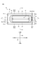
- FIG. 4 is a plan view of the heat absorbing member.
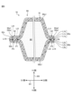
- FIG. 5 is a diagram showing a cross-sectional shape of the heat absorbing member taken along line VV shown in FIG.
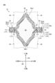
- FIG. 6 is a diagram showing a cross-sectional shape of the heat absorbing member taken along line VI-VI shown in FIG.
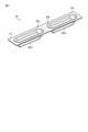
- FIG. 7 is a perspective view showing an exterior body before the heat absorbing agent is accommodated therein.
- FIG. 1 is an exploded perspective view of a battery pack according to a first embodiment of the present disclosure.
- FIG. 2 is an exploded perspective view of the battery unit shown in FIG.
- FIG. 3 is a vertical cross-sectional view of the secondary battery shown in FIG.
- FIG. 4 is a plan view of the
- FIG. 8 is a diagram showing the arrangement of the heat absorbing members when viewed along a direction perpendicular to the axial direction along which the central axis of the secondary battery extends.
- FIG. 9 is a perspective view of a heat absorbing member of a battery pack according to a modified example of the first embodiment of the present disclosure.
- FIG. 10 is a partial cross-sectional view of a battery unit according to a modified example of the first embodiment.
- FIG. 11 is a perspective view of a set of heat absorbing members provided in a battery pack according to a second embodiment of the present disclosure.
- FIG. 12 is a plan view of the pair of heat absorbing members shown in FIG. FIG.
- FIG. 13 is a diagram showing the cross-sectional shape of a pair of heat absorbing members, mainly of the connecting portion, when cut along a plane along the thickness direction of the flange portions of the heat absorbing members.
- FIG. 14 is a perspective view showing the exterior body of a set of heat absorbing members before the heat absorbing agent is placed therein.
- the X direction shown in the drawings corresponds to the width direction of the battery pack 1
- the Y direction corresponds to the depth direction of the battery pack 1
- the Z direction corresponds to the height direction of the battery pack 1.
- the X, Y, and Z directions are perpendicular to each other.
- the side indicated by the arrow is the +X side
- the side opposite the +X side is the -X side.
- the side indicated by the arrow is the +Y side
- the side opposite the +Y side is the -Y side.
- the side indicated by the arrow is the +Z side
- the side opposite the +Z side is the -Z side.
- the X, Y, and Z directions are merely examples, and the present disclosure is not limited to these directions.
- First Embodiment 1 is an exploded perspective view of a battery pack 1 according to a first embodiment of the present disclosure.
- the battery pack 1 can be used as a power source for external devices (not shown) such as electronic devices, electric vehicles, and power tools.
- the battery pack 1 includes an exterior case 10, a control board 20, and a battery unit 30.
- the exterior case 10 is box-shaped and houses the control board 20 and the battery unit 30.
- the exterior case 10 has a first case portion 11 and a second case portion 12.
- a connector 13 is attached to the exterior case 10.
- the connector 13 electrically connects an external device and the battery unit 30 via the control board 20, and supplies (discharges) power from the battery unit 30 to the external device.
- the connector 13 also electrically connects a power source (e.g., a commercial power source) and the battery unit 30 via the control board 20, and supplies (charges) power from the power source to the battery unit 30.
- the control board 20 controls the charging and discharging of the battery unit 30.
- FIG. 2 is an exploded perspective view of the battery unit 30 shown in FIG. 1.
- the battery unit 30 includes a plurality of secondary batteries 40, a plurality of lead plates 50, a holder 60, and a plurality of heat absorption members 70.
- the secondary battery 40 is, for example, a lithium ion battery.
- the secondary battery 40 has a cylindrical shape.
- the secondary battery 40 has a positive terminal 40a and a negative terminal 40b, which are electrodes, at both ends.
- the number of secondary batteries 40 is eight. It goes without saying that the number of secondary batteries 40 is not limited to eight.
- the multiple secondary batteries 40 are arranged in parallel and spaced apart from each other.
- the central axes CL of the multiple secondary batteries 40 are parallel to each other.
- the central axis CL of the secondary batteries 40 is along the Y direction.
- the multiple secondary batteries 40 are arranged in a row such that the orientation of the positive electrode terminal 40a and the orientation of the negative electrode terminal 40b are predetermined.
- the multiple secondary batteries 40 are arranged in two rows. Specifically, four secondary batteries 40 are lined up along the X direction, and two secondary batteries 40 are lined up along the Y direction. It goes without saying that the arrangement of the multiple secondary batteries 40 is not limited to two rows.
- FIG. 3 is a vertical cross-sectional view of the secondary battery 40 shown in FIG. 2.
- the secondary battery 40 includes an electrode assembly 41, a can 42, and a lid 43.
- the can 42 and the lid 43 are made of, for example, iron, stainless steel, or aluminum, and are conductive.
- the electrode assembly 41 is made up of multiple sheet-shaped positive electrodes (not shown) and multiple sheet-shaped negative electrodes (not shown) that are stacked and wound with separators (not shown) between them.
- the can 42 is cylindrical with an opening at one end.
- the can 42 is electrically connected to the negative electrode of the electrode assembly 41 via a current collector foil (not shown).
- the center of the other end face of the can 42 is the negative electrode terminal 40b of the secondary battery 40.
- the lid 43 is plate-shaped and covers the opening on one end of the can 42.
- the lid 43 and the can 42 are electrically insulated by an insulating member (not shown).
- the lid 43 is electrically connected to the positive electrode of the electrode assembly 41 via a current collecting foil.
- the lid 43 has a protrusion 43a and a split valve 43b.
- the protrusion 43a is located in the center of the lid 43.
- the protruding end surface of the protrusion 43a is the positive electrode terminal 40a of the secondary battery 40.
- the protrusion 43a is also provided with a hole 43a1 that connects the inside and outside of the secondary battery 40. There may be multiple holes 43a1.
- the split valve 43b is located inside the protrusion 43a inside the secondary battery 40.
- the split valve 43b separates the space inside the secondary battery 40 that communicates with the hole 43a1 from the space in which the electrode assembly 41 is located.
- the split valve 43b splits to open when the internal pressure of the secondary battery 40 reaches or exceeds a predetermined value.
- a battery thin wall portion 42a is provided on the other end side of the can 42.
- the battery thin wall portion 42a is a portion that is thinner on the other end side of the can 42.
- the other end side of the can 42 splits open from the battery thin wall portion 42a. For example, if the internal pressure of the secondary battery 40 exceeds a predetermined value but the split valve 43b does not open, when the internal pressure of the secondary battery 40 increases further, the other end side of the can 42 splits open from the battery thin wall portion 42a.
- the lead plate 50 shown in FIG. 2 electrically connects multiple secondary batteries 40 in series or parallel.
- the lead plate 50 also electrically connects the multiple secondary batteries 40 to the control board 20.
- the lead plate 50 includes a first lead plate 51 and a second lead plate 52.
- the first lead plate 51 electrically connects two secondary batteries 40.
- the second lead plate 52 electrically connects four secondary batteries 40. It goes without saying that the number of secondary batteries 40 electrically connected to the first lead plate 51 and the second lead plate 52 is not limited to the above number.
- the holder 60 holds a plurality of secondary batteries 40 and a plurality of heat absorption members 70.
- the holder 60 includes a first holder member 61 and a second holder member 62.
- the first holder member 61 holds the -Y side of the plurality of secondary batteries 40.
- the second holder member 62 holds the +Y side of the plurality of secondary batteries 40.
- the heat absorption members 70 absorb heat from the secondary batteries 40.
- the number of heat absorption members 70 is six, but it goes without saying that this is not limited to six and will vary depending on the number and arrangement of the secondary batteries 40.
- FIG. 4 is a plan view of the heat absorbing member 70.
- FIG. 4 corresponds to a plan view of the heat absorbing member 70 when viewed along the thickness direction of the flange portion 92 described below.
- FIG. 5 is a diagram showing the cross-sectional shape of the heat absorption member 70 taken along line V-V shown in FIG. 4.
- FIG. 6 is a diagram showing the cross-sectional shape of the heat absorption member 70 taken along line VI-VI shown in FIG. 4.
- the cross-sectional shapes in FIGS. 5 and 6 correspond to the cross-sectional shape of the heat absorption member 70 when cut along a plane along the thickness direction of the flange portion 92 described below.
- the first direction W1 corresponds to the direction in which line V-V shown in FIG. 4 extends.
- the "S1 side” indicated by the arrow in the first direction W1 corresponds to the side from storage section 91 (described later) toward first side S1 of flange section 92 in the first direction W1 in the plan view of heat absorption member 70 shown in FIG. 4.
- the "S2 side” indicated by the arrow in the first direction W1 corresponds to the side from storage section 91 (described later) toward second side S2 of flange section 92 in the first direction W1 in the plan view of heat absorption member 70 shown in FIG. 4.
- second direction W2 corresponds to the direction in which line VI-VI shown in FIG. 4 extends.
- the "S3 side” indicated by the arrow in the second direction W2 corresponds to the side from accommodation section 91 (described later) toward third side S3 of flange section 92 in the second direction W2 in the plan view of heat absorption member 70 shown in FIG. 4.
- the "S4 side” indicated by the arrow in the second direction W2 corresponds to the side from accommodation section 91 (described later) toward fourth side S4 of flange section 92 in the second direction W2 in the plan view of heat absorption member 70 shown in FIG. 4.
- the third direction W3 is a direction perpendicular to the first direction W1 and the second direction W2.
- the "V1 side" indicated by the arrow in the third direction W3 corresponds to the side from the second convex portion 90b1 to the first convex portion 90a1 of the storage section 91 described later in the third direction W3 in the cross-sectional shape of the heat absorption member 70 shown in Figures 5 and 6.
- V2 side indicated by the arrow in the third direction W3 corresponds to the side from the first convex portion 90a1 to the second convex portion 90b1 of the storage section 91 described later in the third direction W3 in the cross-sectional shape of the heat absorption member 70 shown in Figures 5 and 6.
- the first virtual line Li1 is a virtual line that connects the third side S3 and the fourth side S4 on the S1 side of the accommodation section 91 in the first direction W1.
- the first virtual line portion Li1a included in the first virtual line Li1 corresponds to a portion of the first virtual line Li1 between a first connection point Ps1 of the first virtual line Li1 and a third virtual line Li3 described later and a second connection point Ps2 of the first virtual line Li1 and a fourth virtual line Li4 described later in the plan view of the heat absorption member 70 shown in FIG. 4, the first virtual line portion Li1a overlaps with a fifth virtual point P5 (see FIG. 5) described later.
- the second virtual line Li2 is a virtual line that connects the third side S3 and the fourth side S4 on the S2 side of the accommodation section 91 in the first direction W1.
- the second virtual line portion Li2a of the second virtual line Li2 corresponds to a portion of the second virtual line Li2 between a third connection point Ps3 of the second virtual line Li2 and the third virtual line Li3 described later and a fourth connection point Ps4 of the second virtual line Li2 and the fourth virtual line Li4 described later in the plan view of the heat absorption member 70 shown in FIG. 4.
- the second virtual line portion Li2a overlaps with a second virtual point P2 (see FIG. 5) described later in the plan view of the heat absorption member 70 shown in FIG. 4.
- the third imaginary line Li3 is an imaginary line that connects the first imaginary line Li1 and the second imaginary line Li2 on the S3 side of the center of the storage section 91 in the second direction W2.
- the third imaginary line Li3 overlaps with a third imaginary point P3 (see FIG. 6) described later.
- the fourth imaginary line Li4 is an imaginary line that connects the first imaginary line Li1 and the second imaginary line Li2 on the S4 side of the center of the storage section 91 in the second direction W2.
- the fourth imaginary line Li4 overlaps with a fourth imaginary point P4 (see FIG. 6) described later.
- the first virtual line Li1, the second virtual line Li2, the third virtual line Li3, and the fourth virtual line Li4 are not limited to the positions shown in FIG. 4. Also, in the plan view of the heat absorption member 70 shown in FIG. 4, the first virtual line Li1 and the second virtual line Li2 may be curved. Also, in the plan view of the heat absorption member 70 shown in FIG. 4, the third virtual line Li3 and the fourth virtual line Li4 may be straight.
- the heat absorption member 70 has a heat absorption agent 80 and an exterior body 90 that contains the heat absorption agent 80.
- the heat absorbing agent 80 contains a substance that absorbs heat generated by the secondary battery 40.
- the main component of the heat absorbing agent 80 is a liquid such as water.
- the heat absorbing agent 80 may contain a gelling agent, a surfactant, and an antifreeze agent.
- the heat absorbing agent 80 has fluidity.
- the exterior body 90 has a first exterior part 90a and a second exterior part 90b.
- the first exterior part 90a has a first inner resin layer L1a (corresponding to the "first resin layer"), a first outer resin layer L1b, and a first metal layer L1c between the first inner resin layer L1a and the first outer resin layer L1b.
- first inner resin layer L1a corresponding to the "first resin layer”
- first outer resin layer L1b a first metal layer L1c between the first inner resin layer L1a and the first outer resin layer L1b.
- first metal layer L1c between the first inner resin layer L1a and the first outer resin layer L1b.
- the second exterior part 90b has a second inner resin layer L2a (corresponding to the "second resin layer"), a second outer resin layer L2b, and a second metal layer L2c between the second inner resin layer L2a and the second outer resin layer L2b.
- the second inner resin layer L2a, the second metal layer L2c, and the second outer resin layer L2b are stacked in this order.
- the first inner resin layer L1a and the second inner resin layer L2a face each other.
- the material of the first inner resin layer L1a, the first outer resin layer L1b, the second inner resin layer L2a, and the second outer resin layer L2b is, for example, polyethylene terephthalate alone, but may also be a synthetic resin containing at least one of nylon, polyethylene terephthalate, polypropylene, polyethylene, and polystyrene.
- the material of the first metal layer L1c and the second metal layer L2c is, for example, aluminum.
- the melting points of the first metal layer L1c and the second metal layer L2c are higher than the melting points of the first inner resin layer L1a, the first outer resin layer L1b, the second inner resin layer L2a, and the second outer resin layer L2b.
- the exterior body 90 also has a storage section 91 that stores the heat absorbing agent 80 between the first inner resin layer L1a and the second inner resin layer L2a.
- the first exterior section 90a and the second exterior section 90b have a first convex section 90a1 and a second convex section 90b1 that protrude toward the outside of the heat absorbing member 70 at the center of the exterior body 90 in the first direction W1 and the center of the second direction W2.
- the heat absorbing agent 80 is stored in the space inside the first convex section 90a1 and the second convex section 90b1.
- the portion formed by the first convex section 90a1 and the second convex section 90b1 corresponds to the storage section 91.
- the accommodation section 91 is between the fifth imaginary line Li5 and the sixth imaginary line Li6 in the first direction W1.
- the fifth imaginary line Li5 is an imaginary line that includes the first imaginary point P1 and extends along the third direction W3 in the cross-sectional shape of the heat absorption member 70 shown in FIG. 5.
- the first imaginary point P1 is the point where the first inner resin layer L1a and the second inner resin layer L2a overlap when looking from the inside of the accommodation section 91 toward the S1 side along the first direction W1 in the cross-sectional shape of the heat absorption member 70 shown in FIG. 5.
- the sixth imaginary line Li6 is an imaginary line that includes the second imaginary point P2 and extends along the third direction W3 in the cross-sectional shape of the heat absorption member 70 shown in FIG. 5.
- the second imaginary point P2 is a point where the first inner resin layer L1a and the second inner resin layer L2a overlap when viewed from the inside of the storage section 91 toward the S2 side along the first direction W1 in the cross-sectional shape of the heat absorption member 70 shown in FIG. 5.
- the second imaginary point P2 overlaps with the second imaginary line portion Li2a of the second imaginary line Li2 in the plan view of the heat absorption member 70 shown in FIG. 4.
- the accommodation section 91 is between the seventh imaginary line Li7 and the eighth imaginary line Li8 in the second direction W2.
- the seventh imaginary line Li7 is an imaginary line that includes the third imaginary point P3 and extends along the third direction W3 in the cross-sectional shape of the heat absorption member 70 shown in FIG. 6.
- the third imaginary point P3 is a point where the first inner resin layer L1a and the second inner resin layer L2a overlap when the S3 side is viewed along the second direction W2 from inside the accommodation section 91 in the cross-sectional shape of the heat absorption member 70 shown in FIG. 6. As described above, the third imaginary point P3 overlaps with the third imaginary line Li3 in the plan view of the heat absorption member 70 shown in FIG. 4.
- the eighth imaginary line Li8 is an imaginary line that includes the fourth imaginary point P4 and extends along the third direction W3 in the cross-sectional shape of the heat absorption member 70 shown in FIG. 6.
- the fourth imaginary point P4 is a point where the first inner resin layer L1a and the second inner resin layer L2a overlap when viewed from inside the storage section 91 toward the S4 side along the second direction W2 in the cross-sectional shape of the heat absorption member 70 shown in FIG. 6. As described above, the fourth imaginary point P4 overlaps with the fourth imaginary line Li4 in the plan view of the heat absorption member 70 shown in FIG. 4.
- the exterior body 90 has a flange portion 92 integral with the storage portion 91.
- the flange portion 92 is a portion provided around the entire circumference of the storage portion 91 in the plan view of the heat absorption member 70 shown in FIG. 4.
- the flange portion 92 is also a portion where the first inner resin layer L1a and the second inner resin layer L2a overlap (see FIGS. 5 and 6).
- the flange portion 92 is continuous with the storage portion 91, and extends around the entire circumference of the storage portion 91 in the plan view of the heat absorption member 70 shown in FIG. 4.
- the outer periphery of the flange portion 92 corresponds to the outer periphery of the exterior body 90.
- the flange portion 92 is on the S1 side of the fifth imaginary line Li5 in the first direction W1, and is on the S2 side of the sixth imaginary line Li6 in the first direction W1.
- the flange portion 92 is on the S3 side of the seventh imaginary line Li7 in the second direction W2, and is on the S4 side of the eighth imaginary line Li8 in the second direction W2.
- the outer periphery of the flange portion 92 has a shape having a first side S1, a second side S2, a third side S3, and a fourth side S4.
- the second side S2 is on the opposite side to the first side S1 across the storage section 91.
- the third side S3 connects a first end of the first side S1 to a first end of the second side S2.
- the fourth side S4 connects a second end of the first side S1 to a second end of the second side S2.
- the fourth side S4 is on the opposite side to the third side S3 across the storage section 91.
- the first side S1, the second side S2, the third side S3, and the fourth side S4 are straight lines.
- the first side S1, the second side S2, the third side S3, and the fourth side S4 may be curved.
- the flange portion 92 has an inner resin continuous portion 92a (corresponding to a "continuous portion") in which the first inner resin layer L1a and the second inner resin layer L2a are continuous, all around the periphery of the accommodation portion 91.
- the inner resin continuous portion 92a is a portion in the flange portion 92 where the first inner resin layer L1a and the second inner resin layer L2a are continuous.
- the base material of the first inner resin layer L1a and the base material of the second inner resin layer L2a are integrated, and the first inner resin layer L1a and the second inner resin layer L2a are connected.
- the inner resin continuous portion 92a is a portion that is patterned in the plan view of the heat absorption member 70 shown in FIG. 4.
- the inner resin continuous portion 92a surrounds the entire periphery of the accommodation portion 91 in the plan view of the heat absorption member 70 shown in FIG. 4.
- the outer periphery of the inner resin continuous portion 92a is made up of the first side S1, the second side S2, the third side S3, and the fourth side S4.
- the inner periphery of the inner resin continuous portion 92a is made up of the first virtual line portion Li1a of the first virtual line Li1, the second virtual line portion Li2a of the second virtual line Li2, the third virtual line Li3, and the fourth virtual line Li4.
- the inner resin continuous portion 92a integrally comprises a first continuous portion 92a1 (corresponding to the "first portion"), a second continuous portion 92a2 (corresponding to the "second portion” and the “first second portion"), a third continuous portion 92a3 (corresponding to the "second portion” and the “second second portion”), and a fourth continuous portion 92a4 (corresponding to the "second portion” and the "second second portion”).
- the first continuous portion 92a1 is the portion of the inner resin continuous portion 92a on the first side S1 side of the flange portion 92. Specifically, the first continuous portion 92a1 is the portion of the inner resin continuous portion 92a surrounded by the first side S1, the first virtual line Li1, the third side S3, and the fourth side S4 in the plan view of the heat absorption member 70 shown in FIG. 4.
- the second continuous portion 92a2 is the portion of the inner resin continuous portion 92a on the second side S2 side of the flange portion 92.
- the second continuous portion 92a2 is the portion of the inner resin continuous portion 92a surrounded by the second side S2, the second virtual line Li2, the third side S3, and the fourth side S4 in the plan view of the heat absorption member 70 shown in FIG. 4.
- the third continuous portion 92a3 is the portion of the inner resin continuous portion 92a on the third side S3 side of the flange portion 92. Specifically, the third continuous portion 92a3 is the portion of the inner resin continuous portion 92a surrounded by the third side S3, the third virtual line Li3, the first virtual line Li1, and the second virtual line Li2 in the plan view of the heat absorption member 70 shown in FIG. 4.
- the fourth continuous portion 92a4 is the portion of the inner resin continuous portion 92a on the fourth side S4 side of the flange portion 92. Specifically, the fourth continuous portion 92a4 is the portion of the inner resin continuous portion 92a surrounded by the fourth side S4, the fourth virtual line Li4, the first virtual line Li1, and the second virtual line Li2 in the plan view of the heat absorption member 70 shown in FIG. 4.
- the first continuous portion 92a1 is on the S1 side of the ninth imaginary line Li9 in the first direction W1.
- the ninth imaginary line Li9 is an imaginary line that includes the fifth imaginary point P5 and extends along the third direction W3 in the cross-sectional shape of the heat absorption member 70 shown in FIG. 5.
- the fifth imaginary point P5 overlaps with the first imaginary line portion Li1a in the plan view of the heat absorption member 70 shown in FIG. 4.
- the cross-sectional shape of the heat absorption member 70 shown in FIG. 5 shows a tenth imaginary line Li10.
- the tenth imaginary line Li10 is an imaginary line that extends from the fifth imaginary point P5 to the S1 side along the first direction W1 in the cross-sectional shape of the heat absorption member 70 shown in FIG. 5.
- the tenth imaginary line Li10 corresponds to the boundary line between the first inner resin layer L1a and the second inner resin layer L2a (boundary line for ease of explanation: the same applies below), the boundary line between the first metal layer L1c and the second metal layer L2c, and the boundary line between the first outer resin layer L1b and the second outer resin layer L2b in the cross-sectional shape of the heat absorption member 70 shown in FIG. 5.
- the solid line connecting the first imaginary point P1 and the fifth imaginary point P5 indicates a state in which the surface of the first inner resin layer L1a and the surface of the second inner resin layer L2a overlap in the flange portion 92.
- the first inner resin layer L1a and the second inner resin layer L2a are not continuous, and the base material of the first inner resin layer L1a and the base material of the second inner resin layer L2a are not integrated.
- the first continuous portion 92a1 is a portion of the inner resin continuous portion 92a that is entirely inside at least one of the first metal layer L1c and the second metal layer L2c in the cross-sectional shape of the heat absorption member 70 shown in FIG. 5. Specifically, in the cross-sectional shape of the heat absorption member 70 shown in FIG. 5, the entire first continuous portion 92a1 is inside the metal continuous portion 92b where the first metal layer L1c and the second metal layer L2c are continuous.
- the metal continuous portion 92b is a portion of the first metal layer L1c and the second metal layer L2c that is on the S1 side of the ninth imaginary line Li9 in the first direction W1 in the cross-sectional shape of the heat absorption member 70 shown in FIG. 5.
- the metal continuous portion 92b is a portion where the base material of the first metal layer L1c and the base material of the second metal layer L2c are integrated, and the first metal layer L1c and the second metal layer L2c are continuous without interruption.
- the entire outer surface of the first continuous portion 92a1 overlaps with the inner surface of the metal continuous portion 92b.
- the metal continuous portion 92b may be composed of either the first metal layer L1c or the second metal layer L2c.
- the boundary between the first metal layer L1c and the second metal layer L2c is between the fifth virtual line Li5 and the ninth virtual line Li9 in the first direction W1 in the cross-sectional shape of the heat absorbing member 70 shown in FIG. 5.
- the entire first continuous portion 92a1 overlaps with the metal continuous portion 92b when the flange portion 92 is viewed from the S1 side.
- the first continuous portion 92a1 is not exposed to the outside of the exterior body 90 when the flange portion 92 is viewed from the S1 side.
- the first inner resin layer L1a between the fifth virtual line Li5 and the ninth virtual line Li9 in the first direction W1 overlaps with the first metal layer L1c.
- the second inner resin layer L2a between the fifth virtual line Li5 and the ninth virtual line Li9 in the first direction W1 overlaps with the second metal layer L2c. Therefore, in the cross-sectional shape of the heat absorption member 70 shown in FIG. 5, the first inner resin layer L1a and the second inner resin layer L2a between the fifth virtual line Li5 and the ninth virtual line Li9 in the first direction W1 are not exposed to the outside of the exterior body 90. Therefore, in the cross-sectional shape of the heat absorption member 70 shown in FIG. 5, the first continuous portion 92a1, the first inner resin layer L1a, and the second inner resin layer L2a are not exposed to the outside of the exterior body 90 on the S1 side of the fifth virtual line Li5 in the first direction W1.
- the second continuous portion 92a2 is located on the S2 side of the sixth imaginary line Li6 in the first direction W1 in the cross-sectional shape of the heat absorption member 70 shown in FIG. 5.
- the cross-sectional shape of the heat absorption member 70 shown in FIG. 5 also shows an eleventh imaginary line Li11.
- the eleventh imaginary line Li11 is an imaginary line that extends from the second imaginary point P2 to the S2 side along the first direction W1 in the cross-sectional shape of the heat absorption member 70 shown in FIG.
- the eleventh imaginary line Li11 corresponds to the boundary line between the first inner resin layer L1a and the second inner resin layer L2a in the cross-sectional shape of the heat absorption member 70 shown in FIG. 5.
- the second continuous portion 92a2 has a portion exposed to the outside of the exterior body 90. Specifically, in the cross-sectional shape of the heat absorption member 70 shown in FIG. 5, a portion of the second continuous portion 92a2 is exposed to the outside when the flange portion 92 is viewed from the S2 side to the S1 side along the first direction W1. In the cross-sectional shape of the heat absorption member 70 shown in FIG. 5, the second continuous portion 92a2 is sandwiched between the first metal layer L1c and the second metal layer L2c with the first metal layer L1c and the second metal layer L2c separated from each other.
- the third continuous portion 92a3 is located on the S3 side of the seventh imaginary line Li7 in the second direction W2 in the cross-sectional shape of the heat absorption member 70 shown in FIG. 6.
- the cross-sectional shape of the heat absorption member 70 shown in FIG. 6 also shows a twelfth imaginary line Li12.
- the twelfth imaginary line Li12 is an imaginary line that extends from the third imaginary point P3 to the S3 side along the second direction W2 in the cross-sectional shape of the heat absorption member 70 shown in FIG. 6.
- the twelfth imaginary line Li12 corresponds to the boundary line between the first inner resin layer L1a and the second inner resin layer L2a in the cross-sectional shape of the heat absorption member 70 shown in FIG. 6.
- the third continuous portion 92a3 has a portion exposed to the outside of the exterior body 90 in the cross-sectional shape of the heat absorption member 70 shown in FIG. 6. Specifically, in the cross-sectional shape of the heat absorption member 70 shown in FIG. 6, a portion of the third continuous portion 92a3 is exposed to the outside of the exterior body 90 when the flange portion 92 is viewed from the S3 side to the S4 side along the second direction W2. In the cross-sectional shape of the heat absorption member 70 shown in FIG. 6, the third continuous portion 92a3 is sandwiched between the first metal layer L1c and the second metal layer L2c with the first metal layer L1c and the second metal layer L2c separated from each other.
- the fourth continuous portion 92a4 is located on the S4 side of the eighth imaginary line Li8 in the second direction W2 in the cross-sectional shape of the heat absorption member 70 shown in FIG. 6.
- the cross-sectional shape of the heat absorption member 70 shown in FIG. 6 also shows a thirteenth imaginary line Li13.
- the thirteenth imaginary line Li13 is an imaginary line that extends from the fourth imaginary point P4 to the S4 side along the second direction W2 in the cross-sectional shape of the heat absorption member 70 shown in FIG. 6.
- the thirteenth imaginary line Li13 corresponds to the boundary line between the first inner resin layer L1a and the second inner resin layer L2a in the cross-sectional shape of the heat absorption member 70 shown in FIG. 6.
- the fourth continuous portion 92a4 has a portion exposed to the outside of the exterior body 90 in the cross-sectional shape of the heat absorption member 70 shown in FIG. 6. Specifically, in the cross-sectional shape of the heat absorption member 70 shown in FIG. 6, a portion of the third continuous portion 92a3 is exposed to the outside of the exterior body 90 when the flange portion 92 is viewed from the S4 side to the S3 side along the second direction W2. In the cross-sectional shape of the heat absorption member 70 shown in FIG. 6, the fourth continuous portion 92a4 is sandwiched between the first metal layer L1c and the second metal layer L2c with the first metal layer L1c and the second metal layer L2c separated from each other.
- the S1 side of the flange portion 92 has an outer resin continuous portion 92c where the first outer resin layer L1b and the second outer resin layer L2b are continuous.
- the outer resin continuous portion 92c is located outside the metal continuous portion 92b.
- the outer resin continuous portion 92c is a portion of the first outer resin layer L1b and the second outer resin layer L2b that is on the S1 side of the ninth virtual line Li9 in the first direction W1.
- the outer resin continuous portion 92c the base material of the first outer resin layer L1b and the base material of the second outer resin layer L2b are integrated, and the first outer resin layer L1b and the second outer resin layer L2b are continuous without interruption.
- the entire outer surface of the metal continuous portion 92b overlaps with the inner surface of the outer resin continuous portion 92c.
- the outer resin continuous portion 92c may be composed of either the first outer resin layer L1b or the second outer resin layer L2b.
- the boundary between the first outer resin layer L1b and the second outer resin layer L2b is between the fifth virtual line Li5 and the ninth virtual line Li9 in the first direction W1 in the cross-sectional shape of the heat absorbing member 70 shown in FIG. 5.
- the first outer resin layer L1b and the second outer resin layer L2b are separated from each other while sandwiching the first metal layer L1c and the second metal layer L2c.
- the first outer resin layer L1b and the second outer resin layer L2b are separated from each other while sandwiching the first metal layer L1c and the second metal layer L2c.
- the first distance D1 between the second side S2 and the inner periphery of the second continuous portion 92a2 is shorter than the second distance D2 between the third side S3 and the inner periphery of the third continuous portion 92a3, and the third distance D3 between the fourth side S4 and the inner periphery of the fourth continuous portion 92a4.
- the second distance D2 and the third distance D3 are approximately equal.
- the inner periphery of the second continuous portion 92a2 corresponds to the second imaginary line portion Li2a in the plan view of the heat absorption member 70 shown in FIG. 4.
- the inner periphery of the third continuous portion 92a3 corresponds to the third imaginary line Li3 in the plan view of the heat absorption member 70 shown in FIG. 4.
- the inner periphery of the fourth continuous portion 92a4 corresponds to the fourth imaginary line Li4 in the plan view of the heat absorption member 70 shown in FIG. 4.
- the first distance D1 corresponds to the shortest distance between the inner periphery of the second continuous portion 92a2 and the outer periphery of the portion of the second continuous portion 92a2 exposed to the outside of the exterior body 90.
- the second distance D2 corresponds to the shortest distance between the inner periphery of the third continuous portion 92a3 and the outer periphery of the portion of the third continuous portion 92a3 exposed to the outside of the exterior body 90.
- the third distance D3 corresponds to the shortest distance between the inner periphery of the fourth continuous portion 92a4 and the outer periphery of the portion of the fourth continuous portion 92a4 exposed to the outside of the exterior body 90.
- FIG. 7 is a perspective view showing the exterior body 90 before accommodating the heat absorbing agent 80.
- the exterior body 90 Before accommodating the heat absorbing agent 80, the exterior body 90 has the first exterior portion 90a and the second exterior portion 90b continuous at the portion corresponding to the first side S1 (portion shown by the dashed line) with the first inner resin layer L1a and the second inner resin layer L2a not facing each other.
- the first convex portion 90a1 and the second convex portion 90b1 are formed, for example, by press working. In other words, before accommodating the heat absorbing agent 80, the exterior body 90 is formed by applying press working to a single sheet member.
- the manufacturing process of the heat absorption member 70 includes an injection process, a bending process, and a welding process.
- the injection process, the bending process, and the welding process are performed in this order.
- the injection process is a process in which the heat absorption agent 80 is injected into the inside of at least one of the first convex portion 90a1 and the second convex portion 90b1 of the exterior body 90 shown in FIG. 7.
- the folding process is a process of folding the exterior body 90 at a portion (indicated by a dashed line) corresponding to the first side S1 of the exterior body 90 shown in FIG. 7.
- the exterior body 90 is folded so that the first inner resin layer L1a and the second inner resin layer L2a face each other and overlap (see FIGS. 5 and 6).
- the bending process forms the first continuous portion 92a1 of the inner resin continuous portion 92a, the metal continuous portion 92b, and the outer resin continuous portion 92c shown in FIG. 5. That is, the first continuous portion 92a1, the metal continuous portion 92b, and the outer resin continuous portion 92c correspond to the portion where the first exterior portion 90a and the second exterior portion 90b are continuous in the exterior body 90 before the heat absorbing agent 80 is contained therein.
- the welding process is a process of welding (e.g., ultrasonic welding) the first inner resin layer L1a and the second inner resin layer L2a together.
- the welding process forms the second continuous portion 92a2, the third continuous portion 92a3, and the fourth continuous portion 92a4 of the inner resin continuous portion 92a shown in Figures 4, 5, and 6.
- the second continuous portion 92a2, the third continuous portion 92a3, and the fourth continuous portion 92a4 correspond to the portions where the first inner resin layer L1a and the second inner resin layer L2a are continuous by joining the first inner resin layer L1a and the second inner resin layer L2a by welding.
- the heat absorption member 70 is surrounded by four secondary batteries 40. Specifically, as shown in FIG. 6, the outer surfaces of the two secondary batteries 40 contact the outer surface of the first convex portion 90a1, and the outer surfaces of the two secondary batteries 40 contact the outer surface of the second convex portion 90b1.
- Figure 8 is a diagram showing the arrangement of the secondary battery 40 and the heat absorption member 70 when viewed along a direction perpendicular to the axial direction along which the central axis CL of the secondary battery 40 extends.
- the axial direction is along the Y direction
- the direction perpendicular to the axial direction is along the Z direction.
- the two heat absorption members 70 are lined up along the axial direction.
- the longitudinal direction of the heat absorption members 70 is along the axial direction.
- the two heat absorption members 70 lined up along the axial direction are separated from each other.
- the heat absorption member 70 is arranged in an axial direction such that the first continuous portion 92a1 is closer to the end of the secondary battery 40 (specifically, one of the positive electrode terminal 40a and the negative electrode terminal 40b) than the second continuous portion 92a2, the third continuous portion 92a3, and the fourth continuous portion 92a4.
- the two heat absorption members 70 aligned along the axial direction overlap with the secondary battery 40 in FIG. 8, and are arranged such that the second sides S2 of the flange portions 92 face each other, and the first sides S1 of the flange portions 92 face opposite each other.
- the space between the two heat absorption members 70 is located in the center of the secondary battery 40 in the axial direction.
- the temperature of the exterior body 90 of the heat absorbing member 70 that is in contact with the abnormally heated secondary battery 40 rises, and the second continuous portion 92a2, the third continuous portion 92a3, and the fourth continuous portion 92a4 shown in Figures 4, 5, and 6 melt.
- the entire first continuous portion 92a1 is inside the metal continuous portion 92b.
- the first continuous portion 92a1 is not exposed to the outside of the exterior body 90 when the flange portion 92 is viewed from the S1 side.
- the melting points of the first metal layer L1c and the second metal layer L2c are higher than the melting point of the inner resin continuous portion 92a. Therefore, the flange portion 92 does not split open from the first side S1 side.
- the distance D1 corresponds to the distance along the axial direction between the inner periphery of the second continuous portion 92a2 and the outer periphery of the portion of the second continuous portion 92a2 exposed to the outside of the exterior body 90.
- the distance D2 corresponds to the distance along the direction perpendicular to the axial direction between the inner periphery of the third continuous portion 92a3 and the outer periphery of the portion of the third continuous portion 92a3 exposed to the outside of the exterior body 90.
- the distance D3 corresponds to the distance along the direction perpendicular to the axial direction between the inner periphery of the fourth continuous portion 92a4 and the outer periphery of the portion of the fourth continuous portion 92a4 exposed to the outside of the exterior body 90.
- the first distance D1 is shorter than the second distance D2 and the third distance D3.
- the portion of the flange portion 92 on the second side S2 side will cleave earlier than the portions on the third side S3 side and the fourth side S4 side.
- the heat absorbing agent 80 will leak from the portion of the flange portion 92 on the second side S2 side.
- the heat absorbing agent 80 leaking from the portion on the second side S2 side of the flange portion 92 flows toward between the two heat absorbing members 70 and adheres to the axial center of the secondary battery 40, absorbing the heat of the secondary battery 40.
- the heat absorbing agent 80 then spreads along the outer peripheral surface of the secondary battery 40, absorbing the heat of the secondary battery 40.
- the portion of the flange portion 92 on the third side S3 side and the portion on the fourth side S4 side are further cleaved, causing further leakage of the heat absorbing agent 80.
- the leaked heat absorbing agent 80 flows along the outer peripheral surface of the secondary battery 40 and absorbs the heat of the secondary battery 40.
- the split valve 43b shown in FIG. 3 may open and relatively high temperature gas may spray out from the hole 43a1. At this time, relatively high temperature gas may spray out from the split battery thin-walled portion 42a. At this time, the temperature at both ends of the secondary battery 40 in the axial direction may be higher than the temperature at the center of the secondary battery 40. Even in this case, as described above, the first continuous portion 92a1 overlaps with the metal continuous portion 92b when the flange portion 92 is viewed from the first side S1 side, and is not exposed to the outside of the exterior body 90. Therefore, the portion of the flange portion 92 on the first side S1 side does not split open.
- the area of the secondary battery 40 on the third side S3 side or the area on the fourth side S4 side, which is closer to the hot part, will tear.
- the area of the second side S2 will tear.
- the heat-absorbing agent 80 absorbs the heat of the secondary battery 40 as described above.
- the leaked heat absorbing agent 80 would flow toward both ends of the secondary battery 40 in the axial direction. Therefore, compared to the case where the portion of the flange portion 92 on the second side S2 side cleaves earlier as described above, the contact area between the heat absorbing agent 80 and the secondary battery 40 is smaller, and the heat of the secondary battery 40 is less likely to be absorbed.
- the portion of the flange portion 92 on the second side S2 side cleaves early. Also, when both ends of the secondary battery 40 are hot, the portion of the third side S3 or the portion of the fourth side S4 cleaves, followed by the portion of the second side S2. As a result, the heat absorption efficiency of the heat absorption agent 80 can be improved when the secondary battery 40 generates abnormal heat.
- FIG. 9 is a perspective view of a heat absorbing member 170 of a battery pack 1 according to a modified example of the first embodiment of the present disclosure.
- FIG. 10 is a partial cross-sectional view of a battery unit 30 according to a modified example of the first embodiment.
- FIG. 10 is a diagram showing the cross-sectional shape of the battery unit 30 when cut along a plane perpendicular to the Y direction.
- the heat absorption member 170 of this modified example does not have the first protrusion 90a1 of the heat absorption member 70 of the first embodiment described above.
- the outer surface of the first exterior part 190a of the heat absorption member 170 has a flat surface 190a2.
- the heat absorption member 170 has a second protrusion 190b1 of the second exterior part 190b.
- the flat surface 190a2 and the control board 20 face each other, so that the heat absorption member 170 can be placed between the two secondary batteries 40 and the control board 20.
- the housing portion 191 contacts the two secondary batteries 40.
- the heat absorption member 170 can be placed surrounded by four secondary batteries 40, similar to the heat absorption member 70 of the first embodiment described above.
- the portion of the flange portion 192 on the second side S2 side will cleave early when the secondary battery 40 generates abnormal heat. Therefore, in the battery pack 1 of this modified example, similar to the battery pack 1 of the first embodiment described above, the heat absorption efficiency of the heat absorption agent 80 can be improved when the secondary battery 40 generates abnormal heat.
- the second continuous portion 92a2 may be between the sixth imaginary line Li6 and the fourteenth imaginary line Li14 in the first direction W1 in the cross-sectional shape of the heat absorption member 70 shown in FIG. 5.
- the fourteenth imaginary line Li14 is a virtual line that is between the sixth imaginary point P6, which is the end point on the S2 side of the eleventh imaginary line Li11, and the second imaginary point P2 in the first direction W1 in the cross-sectional shape of the heat absorption member 70 shown in FIG. 5, and extends along the third direction W3.
- the first inner resin layer L1a and the second inner resin layer L2a are not welded to each other in the portion of the flange portion 92 on the S2 side of the fourteenth imaginary line Li14 in the first direction W1, and the first inner resin layer L1a and the second inner resin layer L2a are not continuous.
- the third continuous portion 92a3 may be between the seventh imaginary line Li7 and the fifteenth imaginary line Li15 in the second direction W2 in the cross-sectional shape of the heat absorption member 70 shown in FIG. 6.
- the fifteenth imaginary line Li15 is a virtual line that is between the seventh imaginary point P7, which is the end point on the S3 side of the twelfth imaginary line Li12, and the third imaginary point P3 in the second direction W2 in the cross-sectional shape of the heat absorption member 70 shown in FIG. 6, and extends along the third direction W3.
- the first inner resin layer L1a and the second inner resin layer L2a are not welded to each other in the portion of the flange portion 92 on the S3 side of the fifteenth imaginary line Li15 in the second direction W2, and the first inner resin layer L1a and the second inner resin layer L2a are not continuous.
- the fourth continuous portion 92a4 may be between the eighth imaginary line Li8 and the sixteenth imaginary line Li16 in the second direction W2 in the cross-sectional shape of the heat absorption member 70 shown in FIG. 6.
- the sixteenth imaginary line Li16 is a virtual line that is between the eighth imaginary point P8, which is the end point on the S4 side of the thirteenth imaginary line Li13, and the fourth imaginary point P4 in the second direction W2 in the cross-sectional shape of the heat absorption member 70 shown in FIG. 6, and extends along the third direction W3.
- the first inner resin layer L1a and the second inner resin layer L2a are not welded to each other in the portion of the flange portion 92 on the S4 side of the sixteenth imaginary line Li16 in the second direction W2, and the first inner resin layer L1a and the second inner resin layer L2a are not continuous.
- FIG. 11 is a perspective view of a set of heat absorption members C provided in a battery pack 1 according to a second embodiment of the present disclosure.
- FIG. 12 is a plan view of the set of heat absorption members C shown in FIG. 11.
- the battery pack 1 of the second embodiment includes a plurality of (e.g., three) sets of heat absorption members C.
- the set of heat absorption members C has two heat absorption members 270 and a connecting portion 271 integrally formed therewith.
- the heat absorption member 270 is configured in the same manner as the heat absorption member 70 of the first embodiment described above.
- the heat absorption member 270 has a housing portion 291 and a flange portion 292.
- the two heat absorption members 270 are arranged along the longitudinal direction of the heat absorption member 270 with the second sides S2 of the flange portions 292 facing each other and the first sides S1 of the flange portions 292 facing in opposite directions.
- FIG. 13 is a diagram showing the cross-sectional shape of a pair of heat absorbing members C when cut along a plane along the thickness direction of the flange portion 292 of the heat absorbing member 270, mainly showing the cross-sectional shape of the connecting portion 271.
- the connecting portion 271 connects the portions of the flange portion 292 of the two heat absorbing members 270 on the second side S2 side (i.e., the second continuous portion 292a2 side) to each other.
- the connecting portion 271 also connects the second exterior portions 290b of the two heat absorbing members 270 to each other.
- the cross-sectional shape shown in FIG. 13 shows a 17th virtual line Li17 and an 18th virtual line Li18.
- the 17th virtual line Li17 is a virtual line that extends along the third direction W3 in the cross-sectional shape shown in FIG. 13 and overlaps with the end surface St1 on the second side S2 side of the flange portion 292 of one of the two heat absorbing members 270.
- the 17th virtual line Li17 corresponds to the boundary line between one of the two heat absorbing members 270 and the connecting portion 271.
- the 18th virtual line Li18 is a virtual line that extends along the third direction W3 in the cross-sectional shape shown in FIG. 13 and overlaps with the end surface St2 on the second side S2 side of the flange portion 292 of the other of the two heat absorbing members 270.
- the 18th virtual line Li18 corresponds to the boundary line between the other of the two heat absorbing members 270 and the connecting portion 271.
- the connecting portion 271 has a first connecting resin layer L3a, a second connecting resin layer L3b, and a connecting metal layer L3c between the first connecting resin layer L3a and the second connecting resin layer L3b.
- the first connecting resin layer L3a, the connecting metal layer L3c, and the second connecting resin layer L3b are stacked in this order.
- the first connecting resin layer L3a connects the second inner resin layers L2a of the second exterior parts 290b of the two heat absorption members 270 to each other.
- the first connecting resin layer L3a is continuous with and integral to the second inner resin layers L2a of the two heat absorption members 270.
- the second connecting resin layer L3b connects the second outer resin layers L2b of the second exterior parts 290b of the two heat absorption members 270 to each other.
- the second connecting resin layer L3b is continuous with and integral to the second outer resin layers L2b of the two heat absorption members 270.
- the connecting metal layer L3c connects the second metal layers L2c of the second exterior parts 290b of the two heat absorption members 270 to each other.
- the connecting metal layer L3c is continuous with and integral to the second metal layers L2c of the two heat absorption members 270.
- the connecting portion 271 may connect the first exterior portions 290a of the two heat absorbing members 270 together.
- the set of heat absorption members C has an opening 272.
- the opening 272 is located between the portions of the two heat absorption members 270 on the second side S2 side of the flange portion 292 (i.e., the second continuous portion 292a2 side).
- FIG. 14 is a perspective view showing the exterior body 270c of a set of heat absorbing members C before the heat absorbing agent 80 is placed inside.
- the first exterior part 290a and the second exterior part 290b of the two heat absorbing members 270 and the connecting part 271 are integrated.
- the first inner resin layer L1a and the second inner resin layer L2a do not face each other.
- the connecting portion 271 connects the second exterior portions 290b of the two heat absorption members 270 together.
- the first convex portion 290a1 and the second convex portion 290b1 of the two heat absorption members 270, as well as the opening 272, are formed, for example, by press working.
- the exterior body 270c is formed by applying press working to a single sheet member.
- the above-mentioned injection process, bending process, and welding process are performed on the exterior body 270c to complete a set of heat absorbing members C.
- the set of heat absorption members C is surrounded by four secondary batteries 40, similar to the heat absorption members 270 of the first embodiment described above. Also, as shown in FIG. 12, the set of heat absorption members C is arranged such that the two heat absorption members 270 are aligned along the axial direction.
- the two heat absorption members 270 are each oriented such that the portion of the flange portion 292 on the first side S1 side is closer to the edge of the secondary battery 40 in the axial direction than the portion on the second side S2 side.
- the opening 272 is located in the center of the secondary battery 40 in the axial direction.
- the flange portion 292 of the two heat absorption members 270 first breaks open at the portion on the second side S2 side, similar to the heat absorption member 70 of the first embodiment described above, and the heat absorption agent 80 leaks out from the portion on the second side S2 side.
- the heat absorbing agent 80 then spreads along the outer circumferential surface of the secondary battery 40, absorbing the heat of the secondary battery 40.
- the portion of the flange portion 292 on the third side S3 side and the portion on the fourth side S4 side are further cleaved, causing further leakage of the heat absorption agent 80.
- the leaked heat absorption agent 80 flows along the outer peripheral surface of the secondary battery 40 and absorbs the heat of the secondary battery 40.
- the heat absorption efficiency of the heat absorption agent 80 can be improved when the secondary battery 40 generates abnormal heat.
- a plurality of cylindrical secondary batteries a heat absorbing member having a heat absorbing agent and an exterior body that accommodates the heat absorbing agent;
- the exterior body is a first exterior portion having a first resin layer and a first metal layer overlapping the first resin layer; a second exterior portion having a second resin layer facing the first resin layer and a second metal layer overlapping the second resin layer, a storage section that stores the heat absorbing agent between the first resin layer and the second resin layer; a flange portion in which the first resin layer and the second resin layer overlap each other around the entire periphery of the housing portion, the flange portion has a continuous portion in which the first resin layer and the second resin layer are continuous, the continuous portion being located around the entire periphery of the housing portion,
- the continuous portion has a first portion and a second portion, the first portion is located on the inner side of at least one of the first metal layer and the second metal layer in a cross-sectional shape of the heat absorption member when cut along a plane along a thickness direction of the
- the heat absorbing member includes two heat absorbing members, The two heat absorbing members are aligned along the axial direction and spaced apart from each other.
- a space between the two heat absorbing members is located at a center of the secondary battery in the axial direction;
- a battery pack according to any one of (1) to (3).
- the opening is located at a center of the secondary battery in the axial direction, A battery pack as described in (4).
- the second portion is a first second portion that is a portion on an opposite side to the first portion in the axial direction; and a second second portion that is closer to an end of the secondary battery than the first second portion,
- a distance along the axial direction between an inner periphery of the first second portion and an outer periphery of a portion of the first second portion exposed to the outside is shorter than a distance along the direction perpendicular to the axial direction between an inner periphery of the second second portion and an outer periphery of a portion of the second second portion exposed to the outside.
- a battery pack according to any one of (1) to (5).
Landscapes
- Chemical & Material Sciences (AREA)
- Chemical Kinetics & Catalysis (AREA)
- Electrochemistry (AREA)
- General Chemical & Material Sciences (AREA)
- Engineering & Computer Science (AREA)
- Manufacturing & Machinery (AREA)
- Secondary Cells (AREA)
Priority Applications (2)
| Application Number | Priority Date | Filing Date | Title |
|---|---|---|---|
| JP2025537680A JPWO2025027980A1 (https=) | 2023-08-02 | 2024-05-21 | |
| US19/423,157 US20260112740A1 (en) | 2023-08-02 | 2025-12-17 | Battery pack |
Applications Claiming Priority (2)
| Application Number | Priority Date | Filing Date | Title |
|---|---|---|---|
| JP2023126273 | 2023-08-02 | ||
| JP2023-126273 | 2023-08-02 |
Related Child Applications (1)
| Application Number | Title | Priority Date | Filing Date |
|---|---|---|---|
| US19/423,157 Continuation US20260112740A1 (en) | 2023-08-02 | 2025-12-17 | Battery pack |
Publications (1)
| Publication Number | Publication Date |
|---|---|
| WO2025027980A1 true WO2025027980A1 (ja) | 2025-02-06 |
Family
ID=94394383
Family Applications (1)
| Application Number | Title | Priority Date | Filing Date |
|---|---|---|---|
| PCT/JP2024/018727 Pending WO2025027980A1 (ja) | 2023-08-02 | 2024-05-21 | 電池パック |
Country Status (3)
| Country | Link |
|---|---|
| US (1) | US20260112740A1 (https=) |
| JP (1) | JPWO2025027980A1 (https=) |
| WO (1) | WO2025027980A1 (https=) |
Citations (3)
| Publication number | Priority date | Publication date | Assignee | Title |
|---|---|---|---|---|
| US5709914A (en) * | 1994-01-18 | 1998-01-20 | Hayes; Claude Q. C. | Thermal storage and transfer device |
| WO2010098067A1 (ja) * | 2009-02-24 | 2010-09-02 | パナソニック株式会社 | 電池モジュールとそれを用いた電池モジュール集合体 |
| WO2023132234A1 (ja) * | 2022-01-06 | 2023-07-13 | 株式会社村田製作所 | 電池パック |
-
2024
- 2024-05-21 JP JP2025537680A patent/JPWO2025027980A1/ja active Pending
- 2024-05-21 WO PCT/JP2024/018727 patent/WO2025027980A1/ja active Pending
-
2025
- 2025-12-17 US US19/423,157 patent/US20260112740A1/en active Pending
Patent Citations (3)
| Publication number | Priority date | Publication date | Assignee | Title |
|---|---|---|---|---|
| US5709914A (en) * | 1994-01-18 | 1998-01-20 | Hayes; Claude Q. C. | Thermal storage and transfer device |
| WO2010098067A1 (ja) * | 2009-02-24 | 2010-09-02 | パナソニック株式会社 | 電池モジュールとそれを用いた電池モジュール集合体 |
| WO2023132234A1 (ja) * | 2022-01-06 | 2023-07-13 | 株式会社村田製作所 | 電池パック |
Also Published As
| Publication number | Publication date |
|---|---|
| US20260112740A1 (en) | 2026-04-23 |
| JPWO2025027980A1 (https=) | 2025-02-06 |
Similar Documents
| Publication | Publication Date | Title |
|---|---|---|
| TWI713245B (zh) | 使用包帶的電池單元的排氣結構、電池組及使用電池組的裝置 | |
| JP5541250B2 (ja) | 二次電池 | |
| CN102097644B (zh) | 可再充电电池 | |
| US20230045904A1 (en) | Battery cell, manufacturing method and manufacturing system of same, battery, and electric device | |
| JP7276996B2 (ja) | 電池モジュールおよびそれを含む電池パック | |
| JP2010238649A (ja) | バッテリー装置 | |
| JP7596525B2 (ja) | 電池モジュールおよびその製造方法 | |
| KR100913836B1 (ko) | 향상된 안전성의 파우치형 이차전지 | |
| US20240106025A1 (en) | Battery pack | |
| US20230395949A1 (en) | Battery unit, battery, electric device, and manufacturing method and device of battery unit | |
| KR102800478B1 (ko) | 전지 모듈, 이를 포함하는 전지 팩 및 전지 모듈 제조 방법 | |
| CN117136466A (zh) | 电池单体及其制造方法和设备、电池以及用电装置 | |
| JP2001250517A (ja) | 電 池 | |
| EP4156389B1 (en) | Jig for manufacturing secondary battery | |
| WO2025027980A1 (ja) | 電池パック | |
| JP7484060B2 (ja) | 二次電池およびその製造方法 | |
| JP7177791B2 (ja) | 組電池および電動装置 | |
| WO2017073028A1 (ja) | 電池モジュール | |
| JP7522718B2 (ja) | 二次電池 | |
| JP7529632B2 (ja) | 二次電池 | |
| US20250023137A1 (en) | Battery pack | |
| KR20240083564A (ko) | 전지 모듈 및 이를 포함하는 전지팩 | |
| WO2022196460A1 (ja) | 電気化学セル | |
| JP2019071259A (ja) | 蓄電素子、及び蓄電素子の製造方法 | |
| US20250038302A1 (en) | Heat absorbing member and battery pack |
Legal Events
| Date | Code | Title | Description |
|---|---|---|---|
| 121 | Ep: the epo has been informed by wipo that ep was designated in this application |
Ref document number: 24848641 Country of ref document: EP Kind code of ref document: A1 |
|
| ENP | Entry into the national phase |
Ref document number: 2025537680 Country of ref document: JP Kind code of ref document: A |
|
| WWE | Wipo information: entry into national phase |
Ref document number: 2025537680 Country of ref document: JP |
|
| NENP | Non-entry into the national phase |
Ref country code: DE |