WO2025027818A1 - 転がり軸受、転がり軸受の異常診断装置および転がり軸受の異常診断方法 - Google Patents
転がり軸受、転がり軸受の異常診断装置および転がり軸受の異常診断方法 Download PDFInfo
- Publication number
- WO2025027818A1 WO2025027818A1 PCT/JP2023/028230 JP2023028230W WO2025027818A1 WO 2025027818 A1 WO2025027818 A1 WO 2025027818A1 JP 2023028230 W JP2023028230 W JP 2023028230W WO 2025027818 A1 WO2025027818 A1 WO 2025027818A1
- Authority
- WO
- WIPO (PCT)
- Prior art keywords
- indicator portion
- outer ring
- cage
- rolling bearing
- rolling
- Prior art date
- Legal status (The legal status is an assumption and is not a legal conclusion. Google has not performed a legal analysis and makes no representation as to the accuracy of the status listed.)
- Pending
Links
Images




Classifications
-
- F—MECHANICAL ENGINEERING; LIGHTING; HEATING; WEAPONS; BLASTING
- F16—ENGINEERING ELEMENTS AND UNITS; GENERAL MEASURES FOR PRODUCING AND MAINTAINING EFFECTIVE FUNCTIONING OF MACHINES OR INSTALLATIONS; THERMAL INSULATION IN GENERAL
- F16C—SHAFTS; FLEXIBLE SHAFTS; ELEMENTS OR CRANKSHAFT MECHANISMS; ROTARY BODIES OTHER THAN GEARING ELEMENTS; BEARINGS
- F16C19/00—Bearings with rolling contact, for exclusively rotary movement
- F16C19/22—Bearings with rolling contact, for exclusively rotary movement with bearing rollers essentially of the same size in one or more circular rows, e.g. needle bearings
- F16C19/24—Bearings with rolling contact, for exclusively rotary movement with bearing rollers essentially of the same size in one or more circular rows, e.g. needle bearings for radial load mainly
- F16C19/26—Bearings with rolling contact, for exclusively rotary movement with bearing rollers essentially of the same size in one or more circular rows, e.g. needle bearings for radial load mainly with a single row of rollers
-
- F—MECHANICAL ENGINEERING; LIGHTING; HEATING; WEAPONS; BLASTING
- F16—ENGINEERING ELEMENTS AND UNITS; GENERAL MEASURES FOR PRODUCING AND MAINTAINING EFFECTIVE FUNCTIONING OF MACHINES OR INSTALLATIONS; THERMAL INSULATION IN GENERAL
- F16C—SHAFTS; FLEXIBLE SHAFTS; ELEMENTS OR CRANKSHAFT MECHANISMS; ROTARY BODIES OTHER THAN GEARING ELEMENTS; BEARINGS
- F16C19/00—Bearings with rolling contact, for exclusively rotary movement
- F16C19/52—Bearings with rolling contact, for exclusively rotary movement with devices affected by abnormal or undesired conditions
-
- F—MECHANICAL ENGINEERING; LIGHTING; HEATING; WEAPONS; BLASTING
- F16—ENGINEERING ELEMENTS AND UNITS; GENERAL MEASURES FOR PRODUCING AND MAINTAINING EFFECTIVE FUNCTIONING OF MACHINES OR INSTALLATIONS; THERMAL INSULATION IN GENERAL
- F16C—SHAFTS; FLEXIBLE SHAFTS; ELEMENTS OR CRANKSHAFT MECHANISMS; ROTARY BODIES OTHER THAN GEARING ELEMENTS; BEARINGS
- F16C33/00—Parts of bearings; Special methods for making bearings or parts thereof
- F16C33/30—Parts of ball or roller bearings
- F16C33/38—Ball cages
Definitions
- This disclosure relates to rolling bearings and abnormality diagnosis devices for rolling bearings.
- a coating made of a material different from that of the bearing components is formed on the surface of the cage.
- the coating material that has become mixed into the lubricating oil as wear powder is detected by a detection device, making it possible to detect the presence or absence of damage to the cage and the extent of the damage (for example, Patent Document 1).
- the present disclosure has been made to solve the problems described above, and provides a rolling bearing, a rolling bearing abnormality diagnosis device, and a rolling bearing abnormality diagnosis method that can easily inspect the condition of the rolling bearing cage for damage and wear without using special equipment.
- the rolling bearing of one claim of the present disclosure is a rolling bearing having an outer ring, an inner ring provided inside the outer ring, a plurality of rolling elements that roll between the outer ring and the inner ring, and a retainer that maintains the spacing between adjacent rolling elements and holds the rolling elements, and the retainer has indicator portions on the surfaces that may come into contact with the outer ring, the inner ring, or the rolling elements that are colored in different colors depending on the depth from the surface of said surfaces toward the inside.
- the state of damage and wear of the retainer can be quantitatively determined by observing the retainer, so that diagnosis can be easily performed without using special equipment.
- FIG. 1 is an example of a cross-sectional view taken along a plane perpendicular to a rotation axis of a rolling bearing according to a first embodiment of the present invention
- 1 is an example of a cross-sectional view taken along a plane including a rotation axis of a rolling bearing according to a first embodiment of the present invention
- 4 is an example of a perspective view of a normal cage according to the first embodiment
- FIG. FIG. 4 is an example of a perspective view of a worn cage according to the first embodiment
- 4 is an example of a partial cross-sectional view of the cage according to the first embodiment, taken along a plane perpendicular to the rotation axis, including an indicator portion provided on a pillar portion of the cage.
- FIG. 2 is an example of a partial cross-sectional view of the cage according to the first embodiment, taken along a plane perpendicular to the rotation axis and including an indicator portion provided on an outer peripheral surface of the cage.
- FIG. 1 is an example of a partial cross-sectional view of a cage according to the first embodiment, taken along a plane perpendicular to the rotation axis of the cage including an indicator portion provided on an inner peripheral surface of the cage.
- FIG. 2 is an example of a partial cross-sectional view taken along a plane perpendicular to the rotation axis of a column portion of a cage according to the first embodiment; FIG.
- FIG. 1 is an example of a partial cross-sectional view of a column having an indicator portion according to the first embodiment, taken along a plane perpendicular to a rotation axis.
- 1 is an example of a partial cross-sectional view of a column having a cone-shaped indicator portion according to the first embodiment, cut along a plane perpendicular to a rotation axis.
- FIG. 1 is an example of a partial cross-sectional view of a column having an indicator portion whose diameter changes stepwise, taken along a plane perpendicular to a rotation axis, according to the first embodiment;
- FIG. 13 is an example of a partial cross-sectional view of a column having indicator portions with different depths cut along a cylindrical surface according to the first embodiment.
- FIG. 13 is an example of a partial cross-sectional view of a column having hole indicator portions with different depths cut along a cylindrical surface according to the first embodiment
- FIG. 1 is an example of a partial cross-sectional view of a ring portion on an outer circumferential surface of a cage, the ring portion having indicator portions of different depths according to the first embodiment, cut along a plane perpendicular to the rotation axis
- 13 is an example of a partial cross-sectional view of a ring portion, in which indicator portions of different depths according to the first embodiment are cut along a plane perpendicular to the rotation axis, on the inner peripheral surface of a cage.
- FIG. 13 is an example of a partial cross-sectional view of a ring portion on the outer circumferential surface of a cage, the ring portion having indicator portions with holes of different depths, cut along a plane perpendicular to the rotation axis, according to the first embodiment.
- FIG. 13 is an example of a partial cross-sectional view of a ring portion on the inner peripheral surface of a cage, the ring portion having indicator portions with holes of different depths, cut along a plane perpendicular to the rotation axis, showing the first embodiment.
- FIG. 13 is an example of a partial cross-sectional view of an observation hole showing the second embodiment.
- 13 is an example of a partial cross-sectional view of another observation hole showing the second embodiment.
- FIG. 11 is a diagram showing an example of a configuration of a rolling bearing abnormality diagnosis device according to a third embodiment of the present invention.
- FIG. 11 is another example of a configuration diagram of the rolling bearing abnormality diagnosis device according to the third embodiment.
- FIG. 11 is a diagram showing an example of a hardware configuration of a rolling bearing abnormality diagnosis device according to a third embodiment of the present invention.
- the rolling bearing of this embodiment comprises an outer ring, an inner ring provided inside the outer ring, a plurality of rolling elements that roll between the outer ring and the inner ring, and a retainer that maintains the spacing between adjacent rolling elements and holds the rolling elements.
- the rolling bearing has the function of holding the outer ring and an object connected to the outer ring, and the inner ring and an object connected to the inner ring so that they can rotate relatively around the rotation axis.
- the axis of rotation about which the outer ring and the inner ring rotate relatively is called the rotation axis
- the direction of the rotation axis is called the axial direction
- the direction perpendicular to the axis is called the radial direction.
- the outer side (there are both sides) as seen from the center of the axial direction of the rolling bearing is called the axial outer side
- the outer side as seen from the radial rotation axis of the rolling bearing is called the radial outer side
- the opposite side is called the radial inner side
- the circumferential direction the direction in which a point at a certain radial distance from the rotation axis rotates around the rotation axis.
- the circumferential direction When viewed locally, the circumferential direction is perpendicular to the radial direction.
- the radial outer side is sometimes called the outer circumferential side
- the radial inner side is sometimes called the inner circumferential side.
- the rolling elements basically roll (roll) against the outer periphery of the inner ring and the inner periphery of the outer ring.
- the cage holds the rolling elements so as to maintain the distance between them, so they basically rotate around the rotation axis as the rolling elements move in the circumferential direction.
- misalignment can occur depending on the clearance between the parts, the load conditions, and the wear conditions.
- the wear of the cage is characterized by the fact that it wears out in the following order: cage posts, cage outer peripheral surface (or cage inner peripheral surface), cage inner peripheral surface (or cage outer peripheral surface). It is difficult to quantitatively evaluate the amount of wear at each possible wear location. In other words, simply detecting the total amount of wear powder makes it difficult to detect phenomena in which a specific area is noticeably worn. Diagnosis based only on the total amount of wear powder may lead to an erroneous judgment of the remaining life of the cage.
- the present disclosure aims to solve the problems described above and provide a rolling bearing capable of abnormality diagnosis with improved speed, simplicity, and accuracy, as well as a rolling bearing abnormality diagnosis device and rolling bearing abnormality diagnosis method.
- FIG. 1 is an example of a cross-sectional view cut in a plane perpendicular to the rotation axis of a rolling bearing showing this embodiment.
- FIG. 2 is an example of a cross-sectional view cut in a plane including the rotation axis of a rolling bearing showing this embodiment.
- the rolling bearing 1 comprises an outer ring 4, an inner ring 7 provided inside the outer ring 4, a plurality of rolling elements 8 that roll between the outer ring 4 and the inner ring 7, and a retainer 9 that maintains the spacing between adjacent rolling elements 8 and holds the rolling elements 8.
- the retainer 9 has indicator portions 14 on the surfaces that may come into contact with the outer ring 4, the inner ring 7, or the rolling elements 8, which are colored in different colors depending on the depth from the surface of the surface toward the inside.
- the outer ring 4 and the inner ring 7 rotate relatively around the same rotation axis.
- the rolling elements 8 are provided between the outer ring 4 and the inner ring 7, and basically perform a rolling motion with respect to the outer ring 4 and the inner ring 7.
- the rolling elements 8 roll between the outer ring 4 and the inner ring 7, and revolve around the rotation axis while rotating.
- the surfaces of the outer ring 4 and the inner ring 7 on which the rolling elements 8 roll are called raceway surfaces. That is, the raceway surfaces include the outer ring raceway surface 3, which is the raceway surface of the outer ring 4, and the inner ring raceway surface 6, which is the raceway surface of the inner ring 7.
- the load applied to the bearing is supported by contact between the raceway surfaces (outer ring raceway surface 3, inner ring raceway surface 6) and the rolling elements 8.
- the outer ring 4 has an outer ring inner protruding surface 2 that protrudes radially inwardly from the axially outer side of the outer ring raceway surface 3 of the outer ring 4 to prevent the rolling elements 8 from escaping from the outer ring raceway surface 3.
- the inner ring 7 also has an inner ring outer peripheral surface 5 axially outwardly of the inner ring raceway surface 6.
- the outer ring 4 and the inner ring 7 move (rotate) relative to each other, if one is fixed and considered as the fixed ring, the other becomes a rotating ring.
- the outer ring 4 is connected to one component
- the inner ring 7 is connected to the other component.
- the rolling elements 8 may be "cylindrical rollers", “tapered rollers", or "balls".
- the cage 9 holds the rolling elements 8 so as to maintain the distance between them, so it basically rotates around the axis of rotation as the rolling elements 8 move in the circumferential direction.
- misalignment may occur depending on the clearance between the parts, the load conditions, and the wear conditions.
- FIG. 3 is an example of a perspective view of a normal retainer 9 in this embodiment.
- a normal retainer 9 refers to a retainer 9 before it is damaged or worn.
- the retainer 9 has a rough shape of an annular ring with holes in the same number as the rolling elements 8 so that it fits between the outer ring 4 and the inner ring 7 and maintains the distance between adjacent rolling elements 8.
- the retainer 9 may be configured using a pair of annular parts 10 and a column part 11 that connects the two annular parts 10 in the axial direction.
- the two annular parts 10 are rings that have the same rotation axis as their central axis and have the same outermost diameter and innermost diameter.
- the retainer 9 has annular parts 10 on both axial sides of the rotation axis.
- the column parts 11 include the same number as the number of rolling elements 8 (16 in the example of FIG. 3), and each of the column parts 11 connects two annular parts 10.
- the retainer 9 has a hole formed by a pair of annular portions 10 and two adjacent column portions 11.
- the hole formed by the pair of annular portions 10 and two adjacent column portions 11 is called a pocket portion 12.
- the retainer 9 has pocket portions 12 equal to the number of rolling elements 8, and retains the rolling elements 8 in the pocket portions 12.
- FIG. 3 shows an example in which the retainer 9 has 16 pocket portions 12 and retains the same number of cylindrical rollers.
- the hole (space) formed by a pair of annular portions 10 and two adjacent columnar portions 11 is the pocket portion 12.
- the rolling elements 8 fit into the pocket portion 12, which is a hole (space).
- the movement of the rolling elements 8 is regulated by the configuration in which the cage 9 and the rolling elements 8 fitted into the pocket portion 12 are provided between the outer ring 4 and the inner ring 7.
- the radial movement of the rolling elements 8 is regulated by the outer ring raceway surface 3 and the inner ring raceway surface 6, and the rolling elements 8 rotate on their own axis while revolving circumferentially around the bearing center.
- the cage 9 maintains a distance between each rolling element 8 and its adjacent rolling elements 8 in the circumferential direction, preventing contact between the rolling elements 8.
- the retainer 9 rotates in the same direction as the circumferential rotation of the rolling elements 8. At this time, the retainer 9 is not always in contact with the outer ring raceway surface 3 and the inner ring raceway surface 6 in the radial direction, and the retainer 9 is not always in contact with the rolling elements 8 in the circumferential direction, but is sometimes spaced apart and sometimes in contact.
- the retainer 9 wears out at the above-mentioned contact points as the rolling bearing 1 rotates repeatedly.
- the portions of the retainer 9 that may come into contact with the outer ring 4, the inner ring 7, or the rolling elements 8 are specified in detail.
- the portion of the retainer 9 that may come into contact with the outer ring 4 is the outer ring inner protruding surface 2 (shaded portion in Fig. 2) that protrudes radially inward from the axial outside of the outer ring raceway surface 3 of the outer ring 4.
- the portion of the retainer 9 that may come into contact with the outer ring inner protruding surface 2 is the retainer outer peripheral surface 9a of the annular portion 10 of the retainer 9 (shaded portion in Fig. 2).
- the retainer outer peripheral surface 9a can also be said to be the surface that faces the outer ring 4 on the radial outer side of the rotating shaft of the annular portion 10.
- the portion of the retainer 9 that may come into contact with the inner ring 7 is the inner ring outer peripheral surface 5 (shaded portion in Fig. 2) that is axially outside the inner ring raceway surface 6.
- the part of the cage 9 that can come into contact with the outer peripheral surface 5 of the inner ring is the inner peripheral surface 9b of the annular portion 10 of the cage 9 (the shaded portion in FIG. 2).
- the inner peripheral surface 9b of the cage can be said to be the surface that faces the inner ring 7 on the radially inner side of the rotating shaft of the annular portion 10.
- the part of the retainer 9 where the retainer 9 and the rolling elements 8 can come into contact is the pocket side surface 12a of the column portion 11 in FIG. 3.
- the rolling elements 8 mainly receive load from the inner ring 7 or the outer ring 4.
- the rolling elements 8 that mainly receive the load are those that are within a certain angle range in the circumferential direction from the load direction as viewed from the central axis of rotation.
- the "within a certain angle range from the load direction as viewed from the central axis of rotation” refers to the load bearing zone where the load is applied.
- the rolling elements 8 move by revolving around the axis of rotation while rotating on their own axes. Focusing on one rolling element 8, the rolling element 8 moves from outside the load zone to enter the load zone, passes through the load zone, and leaves the load zone.
- the rolling element 8 When the rolling element 8 passes through the loaded zone and escapes, it accelerates locally due to the fact that slippage has been suppressed by the load it had been under up until that point, and due to the force in the release direction (revolution direction) that occurs as a result of the change from compression to unloading. As the rolling element 8 accelerates, it comes into contact with the cage 9 at the position where the rolling element 8 escapes the loaded zone. Then, at the position where the rolling element 8 escapes the loaded zone, the cage 9 receives a force in the tangential direction of a circumference passing through the center of the radial width of the cage 9. While rotating together with the rolling element 8, the cage 9 receives the force in the tangential direction of the circumference intermittently at the position where the rolling element 8 escapes the loaded zone.
- the cage outer peripheral surface 9a of the cage 9 comes into contact with the outer ring inner protruding surface 2 of the outer ring 4 first, or the cage inner peripheral surface 9b of the cage 9 comes into contact with the inner ring outer peripheral surface 5 of the inner ring 7 first, depends on the type of bearing. Contact between the cage 9 and the rolling elements 8 causes wear on the pocket side surface 12a of the cage 9. When the cage outer peripheral surface 9a of the cage 9 comes into contact with the outer ring inner protruding surface 2 of the outer ring 4, the cage outer peripheral surface 9a of the cage 9 is worn. Also, when the cage inner peripheral surface 9b of the cage 9 comes into contact with the inner ring outer peripheral surface 5 of the inner ring 7, the cage inner peripheral surface 9b of the cage 9 is worn.
- Figure 4 shows an example of a worn retainer 9 when such wear occurs. Comparing it with Figure 3, the state of wear can be seen. In the figure, wear on the pocket side surface 12a of the retainer 9 narrows the circumferential width of the column portion 11 of the retainer 9, and a hole is formed in the central portion of the radial width. Wear on the outer peripheral surface 9a and inner peripheral surface 9b of the retainer 9 narrows the radial width of the annular portion 10 of the retainer 9. As a result, the radial portion of the column portion 11 of the retainer 9 remains, and Figure 4 shows an example where it protrudes radially outward from the annular portion 10.
- the wear of the cage 9 caused by use of the rolling bearing 1 varies greatly depending on the conditions of use, etc., and it is difficult to predict how much wear will progress in any given location. In some cases, wear may progress significantly in some areas. For this reason, it is difficult to quantitatively evaluate the amount of wear in each area that may be subject to wear. For example, it is difficult to evaluate such a situation using the content of coating material in the lubricating oil of conventional technology.
- FIG. 5 is an example of a partial cross-sectional view of the indicator portion 14 of the retainer 9 showing this embodiment, cut along a plane perpendicular to the rotation axis.
- the retainer 9 has an indicator portion 14 on the pocket side surface 12a of the retainer 9, which is a surface that may come into contact with the rolling elements 8 during operation.
- the indicator portion 14 is colored in different colors depending on the depth from the surface of the surface that may come into contact with the rolling elements 8 toward the inside.
- Such an indicator portion 14 makes it possible to quantitatively determine the wear of the pocket side surface 12a of the retainer 9, which is a surface that may come into contact with the rolling elements 8.
- the shaded portion around the indicator portion 14 conveniently represents the pocket side surface hole 13 into which the indicator portion 14 is inserted.
- the retainer 9 may have an indicator portion 14 on a surface perpendicular to the circumferential direction of the column portion 11, which is the surface facing the rolling element 8 of the retainer 9, and the indicator portion 14 has a color that changes gradually from the surface toward the inside in a direction perpendicular to the surface.
- the indicator portion 14 provided on the surface of the retainer 9 that may come into contact with the rolling elements 8 may be embedded in a pocket side hole 13 opened in the surface on which the indicator portion 14 is provided (pocket side surface 12a).
- the depth of the pocket side hole 13 depth direction length of the indicator portion 14
- the radial width of the pocket side hole 13 is preferably less than half the radial thickness of the column portion 11.
- the shape of the indicator portion 14 that appears on the surface on which the indicator portion 14 is provided may be circular as shown in the figure, or may be approximately quadrilateral.
- the indicator portion 14 may be made of a material that is equal to or less hard than the materials of the rolling element 8, outer ring 4, and inner ring 7. By configuring it in this way, it is possible to prevent the indicator portion 14 itself from scratching the rolling element 8 (cylindrical roller 8), outer ring 4, and inner ring 7 when it comes into contact with them, or from being eroded (attacked) by friction.
- the material of the indicator portion 14 may be made of a thermosetting resin or a thermoplastic resin.
- the Vickers hardness of the indicator portion 14 is 50 or less.
- the indicator portion 14 may be made of a material that contains a phosphorescent or fluorescent material to improve visibility.
- the indicator portion 14 is colored differently depending on the depth from the surface on which it is provided in the direction perpendicular to the surface. For example, the color of the indicator portion 14 may change stepwise depending on the depth. When the retainer 9 and the rolling elements 8 come into contact and the retainer 9 wears, the wear occurs first in the shallow portion of the indicator portion 14. An observer can recognize the wear (abrasion) of that portion of the retainer 9 (pocket side surface 12a) from the color of the remaining shallow portion of the indicator portion 14.
- Multiple indicators 14 may be provided on the same surface.
- the indicator portion 14 may be colored in one or more colors.
- the indicator portion 14 may be colored in a combination of red, green, and blue, which are known as the three primary colors, or a combination of blue, yellow, and red, which are used in traffic signals.
- the indicator portion 14 may also be colored in the seven colors of the rainbow, which are red, orange, yellow, green, blue, indigo, and purple.
- the colors may be a gradation in which the colors change continuously.
- the judge who judges whether there is an abnormality or wear prepares a document that describes the relationship between the depth position of the indicator portion 14 and the color.
- the relationship between the depth position of the indicator portion 14 and the color may be displayed on the non-wear surface of the rolling bearing 1.
- the indicator portion 14 may be a colored bottom surface of the pocket side hole 13.
- the color can be identified by observing the bottom surface of the hole (pocket side hole 13). Even if it is only one color, an abnormality can be detected by determining that an abnormality has occurred when the retainer 9 wears and the coloring of the indicator portion 14 appears on the surface, or when the indicator portion 14 is completely worn away.
- the depth of the indicator portion 14 may be set to a depth that serves as a threshold for determining an abnormality.
- the indicator portion 14 is colored on the bottom surface of the pocket side hole 13.
- multiple holes (pocket side hole 13) of different depths may be provided as indicator portion 14, and the bottom surface of the holes (pocket side hole 13) may be colored a different color depending on the depth.
- the bottom surfaces of holes (pocket side hole 13) of the same depth are colored the same color. This is because the wear status can be determined by which colored holes have worn away and which colored holes remain.
- the indicator portion 14 is colored, but the rolling bearing 1 may not be colored, and the state of the hole may be used as the indicator portion 14.
- the color of the indicator portion 14 can be regarded as the color of the member on which the indicator portion 14 is provided. Even with an uncolored indicator portion 14, the hole as the indicator portion 14 remains, and an abnormality can be determined based on whether a hole exists or whether the indicator portion 14 has worn away and disappeared.
- the indicator portion 14 may be set to one depth, or multiple indicator portions 14 may be provided as holes with different depths. In particular, when multiple holes with different depths are provided as the indicator portion 14, holes with different depths as the indicator portion 14 may be provided on the same surface of the cage 9.
- the coloring of the indicator portion 14 may be such that the wall surface of the pocket side hole 13 is colored in a different color depending on the depth. This is because even if the wall surface of the pocket side hole 13 is colored, it is possible to observe it from the outside.
- the retainer 9 may be provided with a plurality of indicator portions 14 with different lengths in the depth direction.
- a plurality of indicator portions 14 with different lengths in the depth direction may be provided on the surface of the retainer 9 that may come into contact with the outer ring 4, the inner ring 7, or the rolling elements 8.
- the retainer 9 may be provided with an indicator portion 14 on one, two, or all of the surfaces of the retainer 9 that may come into contact with the outer ring 4, the inner ring 7, or the rolling elements 8.
- the indicator portion 14 may be colored the same color on all surfaces as long as the color is the same depth. This configuration makes it easier to grasp the amount of wear.
- the indicator portion 14 may be colored the same depth or different colors on all surfaces.
- the indicator portion 14 provided on a surface that should be determined to be abnormal even with a small amount of wear may be colored in a color that indicates abnormality from a shallow portion in the depth direction.
- the coloring of the indicator 14 provided on the surface of the cage 9 that is thinnest in the direction perpendicular to the surface of the cage 9 that may come into contact with the outer ring 4, the inner ring 7, or the rolling element 8 may be a color that indicates an abnormality from a portion that is shallower in the depth direction than the indicator 14 on the other surfaces.
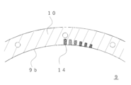
- FIG. 6 is an example of a partial cross-sectional view of the cage 9 showing this embodiment, including the indicator portion 14 provided on the cage outer peripheral surface 9a, cut along a plane perpendicular to the rotation axis.
- the cage 9 has an indicator portion 14 on the cage outer peripheral surface 9a of the cage 9, which is a surface that may come into contact with the outer ring 4 during operation.
- the position of the indicator portion 14 is expressed by the cage outer peripheral surface hole 15 into which the indicator portion 14 is inserted.
- the cage outer peripheral surface 9a on which the indicator portion 14 is provided faces the outer ring inner protruding surface 2 of the outer ring 4, and may come into contact with the outer ring inner protruding surface 2 when the outer ring 4 and the inner ring 7 of the rolling bearing 1 rotate relatively.
- the indicator portion 14 is colored in different colors on the surface that may come into contact with the outer ring 4 depending on the depth in the direction from the surface of the surface toward the inside. Such an indicator portion 14 makes it possible to quantitatively determine the wear of the cage outer peripheral surface 9a of the cage 9, which is a surface that may come into contact with the outer ring 4.
- the retainer 9 may have an indicator portion 14 on a surface perpendicular to the radial direction of the retainer outer peripheral surface 9a, which is the surface facing the outer ring 4 of the retainer 9, and the color of the indicator portion 14 changes gradually from the surface toward the inside in a direction perpendicular to the surface.
- the indicator portion 14 provided on the surface of the retainer 9 that may come into contact with the outer ring 4 may be embedded in a retainer outer peripheral surface hole 15 drilled in the surface on which the indicator portion 14 is provided (the retainer outer peripheral surface 9a).
- the depth of the retainer outer peripheral surface hole 15 is preferably less than half the radial thickness of the annular portion 10. This is because if the depth of the retainer outer peripheral surface hole 15 is too deep, the strength of the retainer 9 decreases.
- the radial width of the retainer outer peripheral surface hole 15 is preferably less than half the axial thickness of the annular portion 10.
- the indicator portion 14 provided on the outer peripheral surface 9a of the retainer 9 may have the same hardness, color, fluorescence/phosphorescence, and colored location as the indicator portion 14 provided on the side surface 12a of the pocket portion, or may have a pattern that is not colored.
- FIG. 7 is an example of a partial cross-sectional view cut by a plane perpendicular to the axis of rotation of the periphery including the indicator portion 14 provided on the inner peripheral surface 9b of the retainer showing this embodiment.
- the retainer 9 has an indicator portion 14 on the inner peripheral surface 9b of the retainer 9, which is a surface that may come into contact with the inner ring 7 during operation.
- the position of the indicator portion 14 is expressed by the retainer inner peripheral surface hole 16 into which the indicator portion 14 is inserted.
- the retainer inner peripheral surface 9b on which the indicator portion 14 is provided faces the inner ring outer peripheral surface 5 of the outer ring 4, and may come into contact with the inner ring outer peripheral surface 5 when the outer ring 4 and the inner ring 7 of the rolling bearing 1 rotate relatively.
- the indicator portion 14 is colored in different colors on the surface that may come into contact with the inner ring 7 depending on the depth in the direction from the surface of the surface toward the inside. Such an indicator portion 14 makes it possible to quantitatively determine the wear of the retainer inner peripheral surface 9b of the retainer 9, which is a surface that may come into contact with the inner ring 7.
- FIG. 7 shows the indicator portion 14 provided on the pocket side surface 12a and the outer peripheral surface 9a of the retainer.
- the retainer 9 may have an indicator portion 14 on a surface perpendicular to the radial direction of the retainer inner circumferential surface 9b, which is the surface facing the inner ring 7 of the retainer 9, and the indicator portion 14 changes color in stages from the surface toward the inside in a direction perpendicular to the surface.
- the indicator portion 14 provided on the surface of the retainer 9 that may come into contact with the inner ring 7 may be embedded in a retainer inner surface hole 16 drilled in the surface on which the indicator portion 14 is provided (retainer inner surface 9b).
- the depth of the retainer inner surface hole 16 is preferably less than half the radial thickness of the annular portion 10. This is because if the retainer inner surface hole 16 is too deep, the strength of the retainer 9 decreases.
- the radial width of the retainer inner surface hole 16 is preferably less than half the axial thickness of the annular portion 10.
- the indicator portion 14 provided on the retainer inner peripheral surface 9b of the retainer 9 may have the same hardness, color, fluorescence/phosphorescence, and colored location as the indicator portion 14 provided on the pocket portion side surface 12a, or may have a pattern that is not colored.
- FIG. 8 is an example of a cross-sectional view of the column portion 11 of the retainer 9 of this embodiment cut along a plane perpendicular to the rotation axis.
- FIG. 9 is an example of a cross-sectional view of the column portion 11 with the indicator portion 14 of the retainer 9 of this embodiment cut along a plane perpendicular to the rotation axis.
- the pocket side surface 12a which is the surface of the retainer 9 that can come into contact with the rolling element 8, exists on both sides in the circumferential direction.
- the pocket side surface 12a is configured as a concave surface in order to come into contact with the rolling element 8.
- FIG. 8 is an example of a cross-sectional view of the column portion 11 of the retainer 9 of this embodiment cut along a plane perpendicular to the rotation axis.
- the pocket side surface 12a which is the surface of the retainer 9 that can come into contact with the rolling element 8 exists on both sides in the circumferential direction.
- the pocket side surface 12a is configured as
- the indicator portion 14 is disposed on the pocket side surface 12a, which is the surface that can come into contact with the rolling element 8, of the column portion 11 of the retainer 9.
- the indicator portion 14 is colored in different colors depending on the depth in the direction from the surface of the surface that can come into contact with the rolling element 8 toward the inside.
- the indicator portion 14 is colored in different colors by different diagonal lines to represent the difference in color. In this case, the depth direction is approximately the circumferential direction.
- FIG. 9 shows an index portion 14 as an example of the pocket side surface 12a, which is the surface that can come into contact with the rolling elements 8 of the retainer 9.
- the same form is obtained when the index portion 14 is provided on the retainer outer peripheral surface 9a, which is the surface that can come into contact with the outer ring 4 of the retainer 9, or on the retainer inner peripheral surface 9b, which is the surface that can come into contact with the inner ring 7 of the retainer 9.
- the depth direction (orientation) of the index portion 14 is perpendicular to the surface on which it is provided, and is the direction (orientation) from the surface toward the inside.
- the depth direction of the index portion 14 provided on the pocket side surface 12a is the circumferential direction
- the depth direction of the index portion 14 provided on the retainer outer peripheral surface 9a or the retainer inner peripheral surface 9b is the radial direction.
- the parts other than the indicator portion 14 are the same as in the conventional method.
- One example of manufacturing the indicator portion 14 is to drill a hole in the surface where the rolling element 8, the outer ring 4 or the inner ring 7 and the cage 9 can come into contact, and insert the indicator portion 14 into the hole.
- the hole is the pocket side hole 13, the cage outer peripheral surface hole 15, or the cage inner peripheral surface hole 16.
- the part to be inserted as the indicator portion 14 is prepared to have the same diameter as the hole drilled in the above surface, or a part with the same interference fit tolerance, and is inserted (or press-fitted) into the hole drilled in the above surface.
- the manufacturing process may be such that an adhesive is applied to the part to be the indicator portion 14, or to one or both of the pocket side hole 13, the cage outer peripheral surface hole 15, and the cage inner peripheral surface hole 16, before insertion. By doing so, it is expected that the indicator portion 14 will not fall off.
- the parts to be inserted as the indicator portion 14 may be prepared as separate members for each different color, and each member of a different color may be inserted separately.
- holes may be provided on the surfaces where the rolling elements 8, outer ring 4 or inner ring 7 and the cage 9 may come into contact, and colored paint may be applied to the holes.
- the paint may be applied to the bottom surface of the hole or to the wall surface of the hole.
- the cross section will be similar to that of Figure 9 (the same applies to the cage outer peripheral surface hole 15 and the cage inner peripheral surface hole 16).
- the indicator portion 14 is not a cross section, but rather the wall surface is visible.
- the bottom surface of the hole will be conical.
- the bottom surface of the hole may be configured as the bottom of the hole (concave conical surface) and the bottom of the hole may be colored ( Figures 6 and 7).
- a hole of a specified depth is drilled to provide the indicator 14. Holes of different depths may be drilled perpendicular to the surface on the surface where the rolling elements 8, outer ring 4 or inner ring 7 come into contact with the cage 9. If holes of different depths are provided in the pocket side holes 13, the holes may be provided in a straight line in the axial direction. If holes of different depths are provided in the cage outer peripheral surface holes 15 or the cage inner peripheral surface holes 16, the holes may be provided in a line in the circumferential direction. This is because it is believed that the wear condition will be uniform in these directions.
- the area of the surface parallel to the surface on which the indicator portion 14 is provided may increase or decrease as the indicator portion 14 becomes deeper in the depth direction. If the area of the surface parallel to the surface on which the indicator portion 14 is provided increases as the indicator portion 14 becomes deeper in the depth direction, the indicator visible from the surface will become larger as wear progresses, making it easier to notice.
- the above-mentioned area or dimensions (length and width) of the indicator portion 14 that appears on the surface correlates with the degree of wear of the retainer 9.
- an operator or a device measures the above-mentioned area or dimensions (length and width) that appear on the surface of the indicator portion 14, the degree of wear of the retainer 9 can be quantitatively grasped.
- the structure of the retainer 9 can be used to increase the area of the surface parallel to the surface on which the indicator portion 14 is provided in the depth direction of the indicator portion 14.
- the retainer 9 is configured by connecting the annular portion 10 and the column portion 11.
- the retainer outer peripheral surface hole 15 or the retainer inner peripheral surface hole 16 can be machined in the axial direction from the axial end face of the annular portion 10 to form a hole that has a trapezoidal (or triangular) shape that continues in the axial direction when viewed from the axial direction.
- the pocket side hole 13 can be machined in the axial direction from the surface side of the column portion 11 that connects to the annular portion 10 to form a similar hole. If the indicator portion 14 is not to be colored, the machined hole serves as the indicator portion 14 as is. If a colored indicator portion 14 is to be used, a colored indicator portion 14 shaped to fit into the hole can be inserted from the axial direction into the hole (pocket side hole 13, cage outer peripheral hole 15, or cage inner peripheral hole 16).
- the area of the surface parallel to the surface on which the indicator portion 14 is provided may be configured to decrease as the indicator portion 14 becomes deeper in the depth direction.
- Such a configuration is effective when the indicator portion 14 is provided on the wall or bottom surface of a hole drilled in the surface of the retainer 9 that may come into contact with the outer ring 4, inner ring 7, or rolling elements 8. This makes it easier for workers or equipment to observe the bottom or wall surface of the hole (pocket portion side hole 13, retainer outer peripheral surface hole 15, or retainer inner peripheral surface hole 16) from the surface. Specific examples are shown below.
- the pocket side hole 13, the cage outer peripheral hole 15, or the cage inner peripheral hole 16, which are holes in which the indicator portion 14 is provided, may have a conical shape that tapers in the depth direction.
- Figure 10 shows an example in which an indicator portion 14 is provided in the pocket side hole 13, but the other indicator portions 14 are similar.
- Figure 10 is an example of a partial cross-sectional view of a column 11 having a cone-shaped indicator portion 14, cut along a plane perpendicular to the axis of rotation.
- the pocket side surface 12a of the column 11 has a cone-shaped hole, which becomes the pocket side surface hole 13.
- a cone-shaped indicator portion 14 is provided in the pocket side surface hole 13.
- the cone-shaped indicator portion 14 changes color in stages in the depth direction.
- the conical holes of the pocket side hole 13, the cage outer peripheral hole 15, and the cage inner peripheral hole 16, the conical index part 14 to be inserted into the deepest part of the hole, and the truncated cone-shaped index part 14 to be inserted next are prepared in advance.
- the deepest part of the hole uses the conical index part 14, which has a larger apex angle than the conical holes of the pocket side hole 13, the cage outer peripheral hole 15, and the cage inner peripheral hole 16, and provides an interference fit effect.
- the truncated cones are inserted in order.
- the index part 14 of the truncated cone is made to have the same apex angle as the index part 14 of the cone inserted earlier, providing an interference fit effect.
- the conical indicator parts 14 and truncated conical indicator parts 14 are separated by different colors and inserted into the holes in sequence.
- the manufacturing process may involve applying adhesive to the indicator parts 14, or to the holes in the pocket side holes 13, the retainer outer peripheral surface holes 15, or the retainer inner peripheral surface holes 16, or both, before insertion. This makes it possible to more firmly fix the pocket side holes 13, the retainer outer peripheral surface holes 15, and the retainer inner peripheral surface holes 16 and the indicator parts 14, preventing them from falling off. Note that drawings showing the conical shapes of the retainer outer peripheral surface holes 15 and the retainer inner peripheral surface holes 16 have been omitted.
- the bottom diameter of the cone and truncated cone indicator 14 (on the surface, the diameter at the surface of the indicator 14) also changes as wear progresses. Therefore, the above configuration makes it possible to evaluate the degree of wear in more detail by observing the bottom diameter at the same time as the color change.
- Figure 11 is an example of a partial cross-sectional view of a column portion 11 having an indicator portion 14 whose diameter changes stepwise, cut along a plane perpendicular to the rotation axis.
- This figure shows an example of a pocket portion side hole 13.
- the pocket portion side hole 13, the retainer outer peripheral surface hole 15, and the retainer inner peripheral surface hole 16 may be cylindrical in shape with a diameter that changes stepwise.
- the pocket side hole 13, the cage outer peripheral surface hole 15, or the cage inner peripheral surface hole 16 are provided in advance.
- a cylindrical hole that changes in step size is provided in the pocket side surface 12a, the cage outer peripheral surface 9a, or the cage inner peripheral surface 9b so that the hole diameter is small at the deepest point and the hole diameter becomes larger toward the surface.
- a cylindrical indicator portion 14 portion having an interference fit tolerance corresponding to the hole diameter is prepared.
- the cylindrical indicator portion 14 portions are prepared in different colors.
- the cylindrical indicator portion 14 portions are inserted into the cylindrical hole that changes in step size, starting from the smallest diameter.
- the insertion process may involve applying adhesive to the indicator portion 14, or the pocket side hole 13, the cage outer peripheral surface hole 15, or the cage inner peripheral surface hole 16, or both, before insertion. This makes it possible to more firmly fix the pocket side hole 13, the retainer outer peripheral hole 15, or the retainer inner peripheral hole 16 to the index portion 14, preventing it from falling off. Note that the conical shapes of the retainer outer peripheral hole 15 and the retainer inner peripheral hole 16 are omitted from the drawings.
- the pocket portion side hole 13, the cage outer peripheral surface hole 15, or the cage inner peripheral surface hole 16 can be made into a cylindrical hole with a stepwise change in diameter, such that the hole diameter is small at its deepest point and becomes larger toward the surface.
- Figure 12 is an example of a partial cross-sectional view of a column portion 11 having indicator portions 14 of different depths, cut with a cylindrical surface.
- the cylindrical surface used for cutting is a cylindrical surface centered on the rotation axis, and is a cylindrical surface that cuts the indicator portions 14.
- the pocket portion side hole 13 may be a plurality of holes of different depths. The positions of the multiple holes of different depths are aligned in a row in the axial direction on the pocket portion side surface 12a, at equal intervals, in order of hole depth.
- six indicator portions 14 are aligned in a row.
- a method for making holes in the pocket side surface 12a that are different in depth and aligned in a row in the axial direction at equal intervals in order of depth will be described.
- cylindrical holes are provided in the pocket side surface hole 13 of the column portion 11 of the retainer 9 in advance, aligned in a row in the axial direction at equal intervals in order of depth.
- a cylindrical indicator portion 14 is prepared that corresponds to the above holes, with the hole diameter being the diameter of the cylinder, the depth of the above holes being the length, and has an interference fit tolerance.
- the prepared cylindrical indicator portions 14 are inserted into the corresponding holes for each different color.
- adhesive may be applied to either the indicator portion 14 or the pocket side surface hole 13, or both, before insertion. In this way, the pocket side surface hole 13 and the indicator portion 14 can be fixed more firmly to prevent them from falling off.
- indicators 14 are provided on holes of different depths aligned in a row in the axial direction at equal intervals in depth order on the side surface 12a of the pocket, the holes will wear away and disappear in order from shallowest to shallowest due to wear, which is expected to improve visibility of the wear progression.
- the diameter of the holes can be any diameter, and they can be conical or cylindrical in shape with a diameter that changes stepwise in the depth direction.
- the effects of using a conical shape or a cylindrical shape with a diameter that changes stepwise in the depth direction are the same as those described above, so they will not be described here.
- multiple holes (pocket side holes 13) of different depths aligned in a row in the axial direction at equal intervals in order of depth can be provided on the pocket side 12a, and these holes can be used as indicators 14 without being colored ( Figure 13).
- the degree of wear of the cage can be determined by the depth of the holes at which indicators 14 remain, even without coloring the indicators 14.
- the retainer 9 may be provided with a mark indicating the presence of the indicator portion 14 on a surface of the retainer 9 other than the surface of the retainer 9 that may come into contact with the outer ring 4, the inner ring 7, and the rolling elements 8.
- the mark indicating the presence of the indicator portion 14 may be on the outer or inner surface of the column portion 11, or on a surface perpendicular to the axial direction of the annular portion 10 (either one or both of the end faces). The mark may be stamped with a punch or the like. When all of the indicator portions 14 have worn away, it can be determined that they have all worn away.
- Figure 14 is an example of a partial cross-sectional view of the annular portion 10 cut in a plane perpendicular to the rotation axis, in which indicator portions 14 of different depths are located on the outer peripheral surface 9a of the cage.
- Figure 15 is an example of a partial cross-sectional view of the annular portion 10 cut in a plane perpendicular to the rotation axis, in which indicator portions 14 of different depths are located on the inner peripheral surface 9b of the cage.
- the cage outer peripheral surface holes 15 and the cage inner peripheral surface holes 16 may be multiple holes of different depths.
- the multiple holes of different depths are positioned in a line in the circumferential direction on the outer peripheral surface 9a of the cage and the inner peripheral surface 9b of the cage at equal intervals in order of hole depth.
- Indicator portions 14 colored in different colors may be embedded in holes of different depths. In the figure, six indicator portions 14 are lined up.
- cage outer peripheral surface holes 15 are drilled in advance on the cage outer peripheral surface 9a
- cage inner peripheral surface holes 16 are drilled in advance on the cage inner peripheral surface 9b.
- the cage outer peripheral surface holes 15 are cylindrical holes in order of depth so that they are in a line in the circumferential direction of the cage outer peripheral surface 9a.
- the cage inner peripheral surface holes 16 are cylindrical holes in order of depth so that they are in a line in the circumferential direction of the cage inner peripheral surface 9b.
- cylindrical indicator parts 14 are prepared that have the same nominal diameter as the hole diameter, the same length as the hole depth, and an interference fit tolerance, corresponding to the cage outer peripheral surface holes 15 and the cage inner peripheral surface holes 16.
- indicator parts 14 of the corresponding depths are inserted into the cage outer peripheral surface holes 15 or the cage inner peripheral surface holes 16 for each different color.
- adhesive may be applied to the indicator portion 14, or to one or both of the retainer outer peripheral surface hole 15 and the retainer inner peripheral surface hole 16. By doing so, the retainer outer peripheral surface hole 15, the retainer inner peripheral surface hole 16, and the indicator portion 14 can be more firmly fixed, preventing them from falling off.
- the diameter of the holes can be any diameter, and they can be conical or cylindrical in shape with a diameter that changes stepwise in the depth direction.
- the effects of using a conical shape or a cylindrical shape with a diameter that changes stepwise in the depth direction are the same as those described above, so they will not be described here.
- holes (retainer outer peripheral surface holes 15 and/or retainer inner peripheral surface holes 16) of different depths that are aligned in a circumferential row at equal intervals in order of depth on the retainer outer peripheral surface 9a and/or retainer inner peripheral surface 9b can be provided, and these holes can be used as indicator parts 14 without being colored ( Figures 16 and 17).
- the degree of wear of the retainer can be determined by the depth of the holes at which indicator parts 14 remain, even without coloring the indicator parts 14.
- the above example shows an example in which a mark is provided at the location of the indicator portion 14 provided on the pocket side surface 12a.
- a mark indicating the presence of the indicator portion 14 may be provided on the surfaces of the retainer 9 other than the surfaces of the retainer 9 that may come into contact with the outer ring 4, the inner ring 7, and the rolling elements 8.
- the wear condition of the retainer 9 of a used rolling bearing 1 can be checked, for example, by the following procedure.
- the worker observes the portion of the cage 9 where the indicator portion 14 is provided. If the observation can be made visually, it is made visually.
- a microscope is inserted between the outer ring 4 and the cage 9, or between the inner ring 7 and the cage 9, and the pocket side surface 12a, the cage outer peripheral surface 9a, and the cage inner peripheral surface 9b, where the indicator portion 14 is provided, are observed with the microscope.
- the observation may be made by photographing the pocket side surface 12a, the cage outer peripheral surface 9a, and the cage inner peripheral surface 9b with a photographing device.
- the images photographed by the photographing device are stored in a memory device.
- the objects to be observed may be one, two, or all of the pocket side surface 12a, the cage outer peripheral surface 9a, and the cage inner peripheral surface 9b.
- the worker determines the color of the indicator portion 14. If there are multiple indicator portions 14 with different depths, the number of them is counted. If the dimensions of the indicator portions 14 vary depending on their depth, the dimensions that appear on the surface are measured.
- the image is captured by the imaging device as described above and stored in a storage device, the image information stored in the storage device may be read out and the image information may be displayed, for example, to determine the color of the indicator portions 14, count the number of indicator portions 14, or measure the dimensions of the indicator portions 14.
- the degree of wear of the observed target portion of the indicator portion 14 is determined from the information obtained in (3) and information prepared in advance that describes the relationship between the depth and color of the indicator portion 14. If there are multiple indicator portions 14 with different depths, the degree of wear of the observed target portion of the indicator portion 14 is determined from the information on the number obtained in (3) and information prepared in advance regarding the relationship between the number of remaining indicator portions 14 and the amount of wear. If the dimensions change depending on the depth of the indicator portion 14, the degree of wear of the observed target portion of the indicator portion 14 is determined from the dimensions obtained in (3) and information prepared in advance regarding the relationship between the depth and dimensions of the indicator portion 14.
- the rolling bearing abnormality diagnosis method of this embodiment can also be understood as follows.
- the rolling bearing abnormality diagnosis method for diagnosing abnormalities in a rolling bearing 1 having an outer ring 4, an inner ring 7 provided inside the outer ring 4, a plurality of rolling elements 8 that roll between the outer ring 4 and the inner ring 7, and a cage 9 that maintains the spacing between adjacent rolling elements 8 and holds the rolling elements 8, includes an imaging step of imaging an indicator portion 14 that is provided on a surface of the cage 9 that may come into contact with the outer ring 4, the inner ring 7, or the rolling elements 8 and is colored in different colors depending on the depth from the surface of the surface toward the inside, an image recording step of recording image information of the indicator portion 14 captured in the imaging step, and a diagnosis step of diagnosing an abnormality in the rolling bearing 1 based on the color of the indicator portion 14 in the recorded image information.
- the video recording process may be performed using a photographing device such as a digital camera.
- the diagnostic process may also be performed on a computer.
- the retainer 9 has indicator portions 14 on the surfaces that may come into contact with the outer ring 4, the inner ring 7, or the rolling elements 8 that are colored differently depending on the depth from the surface of the surface toward the inside, so the wear condition of each part of the retainer can be directly observed by color.
- this embodiment makes it possible to easily inspect the retainer of the rolling bearing 1 for damage and wear conditions without using special equipment.
- the indicator portion 14 which appears in different colors as the indicator portion 14 wears, is directly observed, making it possible to easily evaluate the progress of wear.
- this embodiment there is no need to quantitatively determine the cage wear through analysis, etc., which saves time.
- this embodiment is not affected by grease or oil, which has the effect of improving the accuracy of abnormality diagnosis.
- sample bearing lubricants such as grease or oil to detect wear powder, there are noticeable differences depending on the location where the powder is sampled, which can become a major source of error, but this embodiment allows direct observation of each part of the cage 9, so there is no such source of error.
- the wear of the retainer 9 is characterized by the fact that wear occurs in the order of the column portion 11 of the retainer 9, the retainer outer peripheral surface 9a (or the retainer inner peripheral surface 9b), and the retainer inner peripheral surface 9b (or the retainer outer peripheral surface 9a).
- the rolling bearing 1 of this embodiment is capable of quantitatively evaluating the amount of wear at each wear point. Therefore, even if the wear conditions differ greatly depending on the part of the retainer 9, the rolling bearing 1 can correctly grasp the wear conditions. Therefore, this embodiment can accurately judge the remaining life of the retainer.
- Embodiment 2 In the first embodiment, an example was described in which an indicator portion 14 is provided on the cage 9 of the rolling bearing 1. In the present embodiment, an example is described in which an observation hole for observing the indicator portion 14 is provided on the rolling bearing 1 of the first embodiment. By providing the observation hole, the worker can easily observe the indicator portion 14. In this embodiment, the observation hole, which is a difference from the first embodiment, is mainly described. In this embodiment, terms and symbols that are the same as those in the previous embodiment refer to the same things as in the previous embodiment, unless otherwise specified.
- the rolling bearing 1 of this embodiment comprises an outer ring 4, an inner ring 7 provided inside the outer ring 4, a number of rolling elements 8 that roll between the outer ring 4 and the inner ring 7, and a retainer 9 that maintains the spacing between adjacent rolling elements 8 and holds the rolling elements 8.
- the retainer 9 has indicator portions 14 on the surfaces that may come into contact with the outer ring 4, the inner ring 7, or the rolling elements 8 that are colored in different colors depending on the depth from the surface of said surfaces toward the inside.
- the outer ring 4 or inner ring 7 of the rolling bearing 1 is provided with an observation hole 17 for observing the indicator portion 14 provided on the surface of the retainer 9 that may come into contact with the outer ring 4, inner ring 7, or rolling element 8.
- Figure 18 is an example of a partial cross-sectional view of a rolling bearing 1 including an observation hole 17 according to this embodiment.
- the outer ring 4 has an observation hole 17 that penetrates radially through the axial center, more specifically, an outer ring side pocket observation hole 18a.
- the inner ring 7 also has an observation hole 17 that penetrates radially through the axial center, more specifically, an inner ring side pocket observation hole 18b.
- Figure 19 is an example of a partial cross-sectional view of a rolling bearing 1 including an observation hole 17 different from that described above in this embodiment.
- the outer ring 4 has a radially penetrating observation hole 17, more specifically an outer peripheral observation hole 19, at a position shifted (offset) in one axial direction from the axial center.
- the inner ring 7 also has a radially penetrating observation hole 17, more specifically an inner peripheral observation hole 20, at a position shifted (offset) in one axial direction from the axial center.
- the rolling bearing 1 may be provided with all of the outer ring pocket observation hole 18a, the inner ring pocket observation hole 18b, the outer circumference observation hole 19, and the inner circumference observation hole 20, or may be provided with one or more of them.
- the observation holes 17 may be provided in the outer ring 4 (1) with the outer ring pocket observation hole 18a and the outer circumference observation hole 19, in the inner ring 7 (2) with the inner ring pocket observation hole 18b and the inner circumference observation hole 20, or in the inner ring 7 (3) with all of the outer ring pocket observation hole 18a, the outer circumference observation hole 19, the inner ring hole 18 for observing the pocket side surface, and the inner circumference observation hole 20. Any of the above may be selected according to the usage environment of the bearing.
- the outer ring side pocket observation hole 18a or the inner ring side pocket observation hole 18b is provided in the axial center of the inner ring 7, and is therefore suitable for observing the axial center of the column portion 11 of the cage 9.
- the worker can look through the outer ring side pocket observation hole 18a or the inner ring side pocket observation hole 18b and directly observe the indicator portion 14 provided on the pocket side surface 12a by visual inspection.
- the worker can also look through the outer ring side pocket observation hole 18a and directly observe the indicator portion 14 provided on the cage outer peripheral surface 9a.
- the worker can look through the inner ring side pocket observation hole 18b and directly observe the indicator portion 14 provided on the cage inner peripheral surface 9b by visual inspection.
- the outer peripheral observation hole 19 and the inner peripheral observation hole 20 are provided at positions offset in the axial direction from the axial center of the inner ring 7, 7. Therefore, they are suitable for observing the same side of the cage outer peripheral surface 9a and cage inner peripheral surface 9b of the cage 9 as the observation hole 17 is provided offset in the axial direction.
- the worker can look through the outer peripheral observation hole 19 and directly visually observe the indicator portion 14 provided on the one side of the cage outer peripheral surface 9a.
- the worker can look through the inner peripheral observation hole 20 and directly visually observe the indicator portion 14 provided on the one side of the cage inner peripheral surface 9b.
- the worker may be able to look through the outer peripheral observation hole 19 and directly visually observe the indicator portion 14 provided on the pocket side surface 12a.
- the outer peripheral observation hole 19 is provided midway between the axial center of the outer ring 4 and the axial position where the indicator portion 14 is provided on the cage outer peripheral surface 9a, it becomes possible to observe the indicator portion 14 provided on both the pocket side surface 12a and the cage outer peripheral surface 9a.
- an outer peripheral observation hole 19 When an outer peripheral observation hole 19 is provided, it is provided at a position offset in the axial direction from the axial center, so an indicator portion 14 is provided on the retainer outer peripheral surface 9a on the same axially offset side as the outer peripheral observation hole 19, and no indicator portion 14 is required on the opposite side.
- the worker may be able to look through the inner observation hole 20 and directly visually observe the indicator portion 14 provided on the pocket side surface 12a.
- the inner observation hole 20 is provided midway between the axial center of the inner ring 7 and the axial position where the indicator portion 14 is provided on the cage inner surface 9b, it becomes possible to observe the indicator portion 14 provided on both the pocket side surface 12a and the cage inner surface 9b.
- an indicator portion 14 is provided on the retainer inner peripheral surface 9b on the same axially offset side as the inner peripheral observation hole 20, and an indicator portion 14 need not be provided on the opposite side.
- the rolling bearing 1 may be provided with an observation hole 17, which is a hole for the above-mentioned observation, so that a photographing device such as a microscope can be inserted into the observation hole 17 to observe the indicator portion 14. This has the effect of enabling the degree of wear to be grasped and evaluated more accurately.
- the size of these holes is arbitrary, but it is preferable that the hole diameter is such that a microscope or the like can be inserted.
- observation hole 17 when observation hole 17 is not being used, it may be covered with a lid (not shown).
- a screw may be provided on the inside of observation hole 17, and a screw may be provided on the lid to fasten with this screw, making the lid removable.
- the rolling bearing abnormality diagnosis method described in the first embodiment can be explained as follows when applied to the rolling bearing 1 of this embodiment.
- the rolling bearing abnormality diagnosis method of this embodiment is a method for diagnosing abnormalities in a rolling bearing 1 having an outer ring 4, an inner ring 7 provided inside the outer ring 4, a plurality of rolling elements 8 that roll between the outer ring 4 and the inner ring 7, and a cage 9 that maintains the spacing between adjacent rolling elements 8 and holds the rolling elements 8, and includes an imaging step of imaging, through an observation hole 17 provided in the outer ring 4 or the inner ring 7, an indicator portion 14 that is provided on the surface of the cage 9 that may come into contact with the outer ring 4, the inner ring 7, or the rolling elements 8 and is colored in different colors depending on the depth from the surface of the surface toward the inside, an image recording step of recording the image information of the indicator portion 14 captured in the imaging step, and a diagnosis step of diagnosing an abnormality in the rolling bearing 1 based on the color of the indicator portion 14 in the recorded image information.
- an observation hole 17 is provided that penetrates the outer ring 4 or the inner ring 7 in the radial direction, so that an operator can observe the indicator portion 14 visually or with a photographing device such as a microscope. Therefore, the rolling bearing 1 of this embodiment makes it even easier to inspect the cage of the rolling bearing 1 for damage and wear.
- Embodiment 3 In the second embodiment, an example of a rolling bearing 1 has been described in which an indicator portion 14 is provided on the cage 9 of the rolling bearing 1, and an observation hole 17 is provided on the outer ring 4 or the inner ring 7.
- a rolling bearing abnormality diagnosis device that performs abnormality diagnosis on the rolling bearing 1 of the first or second embodiment will be described.
- terms and symbols that are the same as those in the previous embodiment refer to the same things as in the previous embodiment, unless otherwise specified.
- the rolling bearing 1 of this embodiment comprises an outer ring 4, an inner ring 7 provided inside the outer ring 4, a number of rolling elements 8 that roll between the outer ring 4 and the inner ring 7, and a retainer 9 that maintains the spacing between adjacent rolling elements 8 and holds the rolling elements 8.
- the retainer 9 has indicator portions 14 on the surfaces that may come into contact with the outer ring 4, the inner ring 7, or the rolling elements 8 that are colored in different colors depending on the depth from the surface of said surfaces toward the inside.
- the rolling bearing 1 of this embodiment may have an observation hole 17 for observing the indicator portion 14 provided on the surface of the cage 9 that may come into contact with the outer ring 4, inner ring 7, or rolling element 8, on the outer ring 4 or inner ring 7 of the rolling bearing 1. This is the same as the rolling bearing 1 of embodiment 2.
- the rolling bearing abnormality diagnosis device 100 of this embodiment includes an imaging unit 110 that images an indicator portion 14 that is provided on a surface of the cage 9 that may come into contact with the outer ring 4, the inner ring 7, or the rolling elements 8 and is colored in different colors depending on the depth from the surface of the surface toward the inside, a recording unit 120 that records the video information of the indicator portion 14 captured by the imaging unit 110, and a diagnosis unit 130 that diagnoses an abnormality in the rolling bearing 1 based on the color of the indicator portion 14 in the video information recorded in the recording unit 120.
- the photographing unit 110 may take photographs using a microscope 30 passed through an observation hole 17 provided in the outer ring 4 or inner ring 7 to be observed.
- FIG. 20 is an example of a configuration diagram of the rolling bearing abnormality diagnosis device 100 of this embodiment.
- the rolling bearing abnormality diagnosis device 100 is composed of a photographing unit 110 that photographs the indicator portion 14 of the cage 9, a recording unit 120 that records the image photographed by the photographing unit 110 as image information, and a diagnosis unit 130 that determines the wear state of the cage 9 based on the color of the indicator portion 14 in the image information.
- the output of the diagnosis unit 130 is displayed on a display unit 140.
- the photographing unit 110 photographs the indicator portion 14 of the rolling bearing 1 of the first or second embodiment.
- the outer ring 4 or the inner ring 7 of the cage 9 may be able to photograph the indicator portion 14, which is colored in different colors depending on the depth from the surface of the surface toward the inside, on the surface that may come into contact with the outer ring 4, the inner ring 7, or the rolling element 8, without disassembly or the like.
- the photographing unit 110 of the rolling bearing abnormality diagnosis device 100 photographs the indicator portion 14 directly.
- the cage 9 and the outer ring 4, or the cage 9 and the inner ring 7 may be photographed using a microscope.
- the photographing unit 110 may be called a photographing device, or a microscope and a photographing device.
- the photographing device is a digital camera, and the photographed image becomes video information and becomes digital data.
- FIG. 21 is an example of a configuration diagram of a rolling bearing abnormality diagnosis device 100 for diagnosing abnormalities in a rolling bearing 1 according to embodiment 2.
- the rolling bearing 1 has an observation hole 17 for observing an indicator portion 14 provided on the surface of the cage 9 that may come into contact with the outer ring 4, the inner ring 7, or the rolling elements 8.
- the photographing unit 110 inserts a microscope through the observation holes 17 (outer ring side pocket observation hole 18a, inner ring side pocket observation hole 18b, outer periphery observation hole 19, inner periphery observation hole 20) to photograph the indicator portion 14.
- the photographing unit 110 can be said to be both a microscope and a photographing device.
- the recording unit 120 records the video information captured by the imaging unit 110 in a storage device.
- the diagnosis unit 130 diagnoses abnormalities in the rolling bearing 1 based on the color of the indicator portion 14 in the video information recorded in the recording unit 120.
- the diagnosis unit 130 has in advance the type of color that the indicator portion 14 has, information on each color, and information on the depth to which each color is colored (color information of the indicator portion).
- the diagnosis unit 130 refers to the color information of the indicator portion and searches for the indicator portion 14 in the video information using the color as a clue.
- the diagnosis unit 130 compares the color information of the pixel in the video information of the indicator portion 14 with the color information of the indicator portion, and obtains the depth range of the indicator portion 14 colored with that color from the color information of the indicator portion that matches the color information of the pixel in the video information.
- the diagnosis unit 130 outputs a representative value of the obtained depth range of the indicator portion 14. This output value becomes the amount of wear of the corresponding portion of the cage 9.
- the display unit 140 displays a representative value of the depth range of the indicator unit 14 output by the diagnosis unit 130.
- the recording unit 120 and the diagnosis unit 130 may be realized by the computer 200.
- FIG. 22 is a hardware configuration diagram of a computer 200 that realizes the recording unit 120 and diagnosis unit 130 of the rolling bearing abnormality diagnosis device 100.
- the computer 200 has a memory unit 230 that stores digital information, a central processing unit 210 (central processing unit) that processes information based on the information stored in the memory unit 230, a bus 220 that connects the central processing unit 210 and the memory unit 230, and an external interface 240 that is connected to the bus 220 and interfaces with an external device.
- the external interface 240 is connected to an imaging device 250 or a display device 260.
- the memory unit 230 may be realized by a semiconductor memory or a magnetic storage medium such as a hard disk.
- the photographing unit 110 is executed by an imaging device 250 such as a digital camera, and the captured image information is input to the computer 200 via the external interface 240.
- the recording unit 120 is executed by storing the image information input from the external interface 240 in the memory unit 230.
- the diagnosis unit 130 executes information processing by the central processing unit 210 to determine the amount of wear of the retainer 9 from the image information stored in the memory unit 230 and the color information of the indicator part.
- the output of the diagnosis unit 130 is output to the display device 260 via the external interface 240 and displayed.
- the indicators 14 are provided on the surfaces of the retainer 9 that may come into contact with the outer ring 4, the inner ring 7, or the rolling elements 8 and are colored in different colors depending on the depth from the surface of the surface toward the inside.
- the diagnostic unit 130 then photographs the indicators 14 in the photographed image to determine the degree of wear of the retainer 9. This allows the operator to determine the degree of wear of the retainer 9 even if he or she does not remember the color information of the indicators 14.
- the indicator portion 14 of the retainer 9 can be easily photographed using a microscope to check the wear of the retainer 9.
- the wear conditions of the pocket side surface 12a, the cage outer peripheral surface 9a, and the cage inner peripheral surface 9b can be easily checked, so that even if any part is extremely worn, an abnormality in the rolling bearing can be detected at an early stage.
Landscapes
- Engineering & Computer Science (AREA)
- General Engineering & Computer Science (AREA)
- Mechanical Engineering (AREA)
- Rolling Contact Bearings (AREA)
Priority Applications (2)
| Application Number | Priority Date | Filing Date | Title |
|---|---|---|---|
| PCT/JP2023/028230 WO2025027818A1 (ja) | 2023-08-02 | 2023-08-02 | 転がり軸受、転がり軸受の異常診断装置および転がり軸受の異常診断方法 |
| JP2025503402A JP7790627B2 (ja) | 2023-08-02 | 2023-08-02 | 転がり軸受、転がり軸受の異常診断装置および転がり軸受の異常診断方法 |
Applications Claiming Priority (1)
| Application Number | Priority Date | Filing Date | Title |
|---|---|---|---|
| PCT/JP2023/028230 WO2025027818A1 (ja) | 2023-08-02 | 2023-08-02 | 転がり軸受、転がり軸受の異常診断装置および転がり軸受の異常診断方法 |
Publications (1)
| Publication Number | Publication Date |
|---|---|
| WO2025027818A1 true WO2025027818A1 (ja) | 2025-02-06 |
Family
ID=94394881
Family Applications (1)
| Application Number | Title | Priority Date | Filing Date |
|---|---|---|---|
| PCT/JP2023/028230 Pending WO2025027818A1 (ja) | 2023-08-02 | 2023-08-02 | 転がり軸受、転がり軸受の異常診断装置および転がり軸受の異常診断方法 |
Country Status (2)
| Country | Link |
|---|---|
| JP (1) | JP7790627B2 (https=) |
| WO (1) | WO2025027818A1 (https=) |
Cited By (1)
| Publication number | Priority date | Publication date | Assignee | Title |
|---|---|---|---|---|
| CN119827514A (zh) * | 2025-03-14 | 2025-04-15 | 潍坊市宇宏石油机械有限公司 | 一种轴承磨损性能检测装置 |
Citations (6)
| Publication number | Priority date | Publication date | Assignee | Title |
|---|---|---|---|---|
| JPS5241803U (https=) * | 1975-09-17 | 1977-03-25 | ||
| JPS57182644U (https=) * | 1981-05-15 | 1982-11-19 | ||
| JPS58106633U (ja) * | 1982-01-15 | 1983-07-20 | 豊生ブレ−キ工業株式会社 | 摩耗進行状況の視認容易なデイスクブレ−キパツド |
| JPH1096426A (ja) * | 1996-09-20 | 1998-04-14 | Nippon Seiko Kk | 高速で使用する転がり軸受用保持器とその製造方法 |
| JP2006509975A (ja) * | 2002-12-16 | 2006-03-23 | ミョーニク ゲーエムベーハー | 複合された潤滑材料を有する転がり軸受 |
| JP2010127367A (ja) * | 2008-11-27 | 2010-06-10 | Ntn Corp | 転がり軸受 |
Family Cites Families (4)
| Publication number | Priority date | Publication date | Assignee | Title |
|---|---|---|---|---|
| JP2004076928A (ja) | 2002-06-19 | 2004-03-11 | Nsk Ltd | 転がり軸受用合成樹脂製保持器及び転がり軸受 |
| JP2014066310A (ja) | 2012-09-26 | 2014-04-17 | Nsk Ltd | 転がり軸受、異常診断装置、及び異常診断方法 |
| JP2017206159A (ja) | 2016-05-19 | 2017-11-24 | 横浜ゴム株式会社 | 空気入りタイヤ |
| JP7388839B2 (ja) | 2019-07-22 | 2023-11-29 | クボタ環境エンジニアリング株式会社 | 回転機器及び摩耗点検方法 |
-
2023
- 2023-08-02 JP JP2025503402A patent/JP7790627B2/ja active Active
- 2023-08-02 WO PCT/JP2023/028230 patent/WO2025027818A1/ja active Pending
Patent Citations (6)
| Publication number | Priority date | Publication date | Assignee | Title |
|---|---|---|---|---|
| JPS5241803U (https=) * | 1975-09-17 | 1977-03-25 | ||
| JPS57182644U (https=) * | 1981-05-15 | 1982-11-19 | ||
| JPS58106633U (ja) * | 1982-01-15 | 1983-07-20 | 豊生ブレ−キ工業株式会社 | 摩耗進行状況の視認容易なデイスクブレ−キパツド |
| JPH1096426A (ja) * | 1996-09-20 | 1998-04-14 | Nippon Seiko Kk | 高速で使用する転がり軸受用保持器とその製造方法 |
| JP2006509975A (ja) * | 2002-12-16 | 2006-03-23 | ミョーニク ゲーエムベーハー | 複合された潤滑材料を有する転がり軸受 |
| JP2010127367A (ja) * | 2008-11-27 | 2010-06-10 | Ntn Corp | 転がり軸受 |
Cited By (1)
| Publication number | Priority date | Publication date | Assignee | Title |
|---|---|---|---|---|
| CN119827514A (zh) * | 2025-03-14 | 2025-04-15 | 潍坊市宇宏石油机械有限公司 | 一种轴承磨损性能检测装置 |
Also Published As
| Publication number | Publication date |
|---|---|
| JP7790627B2 (ja) | 2025-12-23 |
| JPWO2025027818A1 (https=) | 2025-02-06 |
Similar Documents
| Publication | Publication Date | Title |
|---|---|---|
| CN103189663B (zh) | 制动盘和用于检验制动盘磨损的方法 | |
| JP7592062B2 (ja) | 軸受監視/解析方法 | |
| CN110514443B (zh) | 一种航空轴承保持架打滑率的非接触式测量方法 | |
| JP7790627B2 (ja) | 転がり軸受、転がり軸受の異常診断装置および転がり軸受の異常診断方法 | |
| US12071984B2 (en) | Rolling bearing with monitoring device | |
| CA2638604A1 (en) | Method and apparatus for bearing monitoring | |
| JP2016531250A (ja) | 歯車装置用転がり軸受 | |
| US20230204459A1 (en) | Rolling bearing with integrated optical fiber sensor | |
| JP2014077641A (ja) | 転がり軸受用保持器のポケット隙間を検査する方法 | |
| US6789949B2 (en) | Roller bearing having streaked grinding trail on roller end face | |
| US9410580B2 (en) | Mechanical system equipped with active microcapsules for condition monitoring | |
| JP2021032769A (ja) | 転がり軸受の状態監視方法及び状態監視装置 | |
| DE102014104964A1 (de) | Verfahren zur Identifikation kritischer Betriebsbedingungen von Wälzlagern | |
| US5129860A (en) | Homokinetic universal joint | |
| JP2005344842A (ja) | 監視装置及び監視方法 | |
| US12215740B2 (en) | System for determining at least one defect of a bearing and associated method | |
| US4625567A (en) | Method and apparatus for the measurement of bearing loads using a ductile wire insert | |
| CN117266300A (zh) | 用于确定轴承的磨损的系统及相关方法 | |
| Rabeyee et al. | Diagnosing the change in the internal clearances of rolling element bearings based on vibration signatures | |
| JPWO2025027818A5 (https=) | ||
| CN110940520A (zh) | 用于检测轴承中的初期损坏的方法 | |
| JP2014066310A (ja) | 転がり軸受、異常診断装置、及び異常診断方法 | |
| JP2014066622A (ja) | 異常診断装置及び異常診断方法 | |
| US20080260316A1 (en) | Rolling Bearing | |
| Lacey | Using vibration analysis to detect early failure of bearings |
Legal Events
| Date | Code | Title | Description |
|---|---|---|---|
| WWE | Wipo information: entry into national phase |
Ref document number: 2025503402 Country of ref document: JP |
|
| 121 | Ep: the epo has been informed by wipo that ep was designated in this application |
Ref document number: 23947615 Country of ref document: EP Kind code of ref document: A1 |
|
| NENP | Non-entry into the national phase |
Ref country code: DE |