WO2025027721A1 - リアクトル装置およびリアクトル装置の製造方法 - Google Patents
リアクトル装置およびリアクトル装置の製造方法 Download PDFInfo
- Publication number
- WO2025027721A1 WO2025027721A1 PCT/JP2023/027879 JP2023027879W WO2025027721A1 WO 2025027721 A1 WO2025027721 A1 WO 2025027721A1 JP 2023027879 W JP2023027879 W JP 2023027879W WO 2025027721 A1 WO2025027721 A1 WO 2025027721A1
- Authority
- WO
- WIPO (PCT)
- Prior art keywords
- winding
- reactor device
- extension direction
- coils
- disk
- Prior art date
- Legal status (The legal status is an assumption and is not a legal conclusion. Google has not performed a legal analysis and makes no representation as to the accuracy of the status listed.)
- Pending
Links
Images








Classifications
-
- H—ELECTRICITY
- H01—ELECTRIC ELEMENTS
- H01F—MAGNETS; INDUCTANCES; TRANSFORMERS; SELECTION OF MATERIALS FOR THEIR MAGNETIC PROPERTIES
- H01F27/00—Details of transformers or inductances, in general
- H01F27/08—Cooling; Ventilating
-
- H—ELECTRICITY
- H01—ELECTRIC ELEMENTS
- H01F—MAGNETS; INDUCTANCES; TRANSFORMERS; SELECTION OF MATERIALS FOR THEIR MAGNETIC PROPERTIES
- H01F30/00—Fixed transformers not covered by group H01F19/00
- H01F30/06—Fixed transformers not covered by group H01F19/00 characterised by the structure
- H01F30/08—Fixed transformers not covered by group H01F19/00 characterised by the structure without magnetic core
-
- H—ELECTRICITY
- H01—ELECTRIC ELEMENTS
- H01F—MAGNETS; INDUCTANCES; TRANSFORMERS; SELECTION OF MATERIALS FOR THEIR MAGNETIC PROPERTIES
- H01F37/00—Fixed inductances not covered by group H01F17/00
Definitions
- This disclosure relates to a reactor device and a method for manufacturing a reactor device.
- a reactor device is provided to suppress sudden fluctuations in the current flowing through electronic devices.
- Some reactor devices have multiple coils wound in multiple rows to reduce high-frequency loss.
- An example of this type of coil is disclosed in Patent Document 1.
- the alpha winding coil disclosed in Patent Document 1 is a disk coil wound in multiple rows.
- This disclosure has been made in consideration of the above-mentioned circumstances, and aims to provide a reactor device with high cooling performance and a method for manufacturing a reactor device.
- the reactor device of the present disclosure includes a plurality of winding cores, a plurality of disc coils, a retaining member, and a pair of frames.
- the plurality of winding cores have a columnar or tubular shape and are aligned in the extension direction of the central axis.
- a plurality of disc coils are provided for each winding core and aligned in the extension direction.
- the retaining member maintains the relative positional relationship of the plurality of disc coils to each other.
- the pair of frames sandwich the plurality of winding cores, the plurality of disc coils, and the retaining member in the extension direction. Adjacent disc coils are positioned with a gap therebetween.
- Each of the disc coils is formed by a winding wound around a plurality of winding positions aligned in the extension direction on the corresponding winding core. Adjacent winding positions are separated from each other by an interval in the extension direction that is greater than the width of the winding.
- the reactor device comprises a plurality of disc coils provided on each winding core, with adjacent disc coils positioned with a gap therebetween.
- Each disc coil is formed by a winding wound around a corresponding winding core at a plurality of winding positions aligned in the extension direction of the central axis. Adjacent winding positions are separated from each other by a distance greater than the width of the winding in the extension direction of the central axis. This allows air to flow through the gaps between the disc coils and inside each disc coil, resulting in a reactor device with high cooling performance.
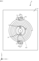
- FIG. 1 is a front view of a reactor device according to a first embodiment
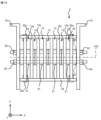
- 2 is a cross-sectional view of the reactor device according to the first embodiment taken along line II-II in FIG. 3 is a cross-sectional view of the reactor device according to the first embodiment taken along line III-III in FIG. 4 is a cross-sectional view of the reactor device according to the first embodiment taken along line IV-IV in FIG. 2
- 1 is a cross-sectional view of a reactor device according to a first embodiment
- FIG. 1 is a diagram showing wires for forming a disk coil according to the first embodiment
- FIG. 1 is a diagram showing a winding for forming a disk coil according to the first embodiment; A flowchart showing an example of a method for manufacturing a reactor device according to the first embodiment.
- FIG. 1 is a diagram showing an example of a winding method according to the first embodiment;
- FIG. 1 is a diagram showing an example of a winding method according to the first embodiment;
- FIG. 1 is a diagram showing an example of a winding method according to the first embodiment;
- FIG. 1 is a diagram showing a jig for winding a winding according to the first embodiment;
- FIG. 1 is a diagram showing an example of a winding method according to the first embodiment
- 11 is a cross-sectional view of a reactor device according to a second embodiment of the present invention
- 15 is a cross-sectional view of the reactor device according to the second embodiment taken along line XV-XV in FIG. 11
- 11 is a cross-sectional view of a reactor device according to a third embodiment.
- 11 is a cross-sectional view of a reactor device according to a third embodiment.
- FIG. 1 is a cross-sectional view of a reactor device according to a first modified example of the embodiment
- FIG. 11 is a cross-sectional view of a reactor device according to a second modified example of the embodiment;
- the reactor device 1 includes a maintaining member that maintains the relative positional relationship between the multiple disk coils 12.
- the reactor device 1 includes, as maintaining members, at least one first spacer 14 provided in the gap 13 between the disk coils 12, and multiple second spacers 15 provided for each winding core 11.
- the reactor device 1 includes multiple first spacers 14 provided in the gap 13 between the disk coils 12.
- the reactor device 1 comprises a pair of frames 16 that sandwich a plurality of winding cores 11, a plurality of disk coils 12, and a plurality of first spacers 14 and a plurality of second spacers 15, which are retaining members, in the direction of extension of the central axis AX1.
- the reactor device 1 includes a plurality of first bolts 17 that penetrate the first spacer 14 and the second spacer 15 in the direction of extension of the central axis AX1 and are fixed to a pair of frames 16.
- the first bolts 17 are fixed to the pair of frames 16 by fastening the first fastening members 18.
- the reactor device 1 further includes a pair of end spacers 19, each of which is positioned between the disk coil 12 and the frame 16.
- the end spacers 19 are provided between the disk coil 12 and the frame 16 that are positioned at the ends in the arrangement direction.
- the length L1 of the winding core 11 in the extension direction of the central axis AX1 is longer than the length L2 of the disk coil 12 in the extension direction of the central axis AX1.
- a disk coil 12 is formed by winding one winding 12a around winding positions 11a and 11b. Adjacent winding positions 11a and 11b on the outer circumferential surface of the winding core 11 are spaced apart by a distance greater than the width of the winding 12a. That is, as shown in FIG. 4, the distance D1 between the winding positions 11a and 11b is greater than the width W1 in the extension direction of the central axis AX1 of the winding 12a. It is preferable that the distance D1 is greater than twice the width W1.
- the part of the disc coil 12 wound around the winding position 11a and the other part of the disc coil wound around the other winding position are spaced apart from each other in the direction of extension of the central axis AX1.
- a gap 12b is formed between the part of the winding 12a wound around the winding position 11a and the part of the winding 12a wound around the winding position 11b.
- Adjacent disc coils 12 are electrically connected.
- the start of one of the adjacent disc coils 12 is electrically connected to the end of the other.
- one end of the winding 12a forming each disc coil 12 on the positive side of the X-axis is the start of the winding
- the other end of the winding 12a is the end of the winding.
- the start of the winding of one disc coil 12 located on the negative side of the X-axis is electrically connected to the end of the winding of the other disc coil 12.
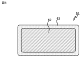
- the winding 12a is formed of a plurality of strands 61 as shown in FIG. 7.
- the winding 12a is formed by stacking a plurality of strands 61, for example, three strands 61, and winding an insulating tape 64 made of, for example, enamel, around the three stacked strands 61.
- the winding 12a formed as described above is wound around the winding core 11 in a flatwise manner to form the disk coil 12.
- each first spacer 14 is provided in a gap 13 and abuts against two disk coils 12 that sandwich the gap 13.
- the first spacer 14 is formed of an insulating material such as resin or ceramic.
- the first spacer 14 is preferably formed of an elastically deformable insulating material, for example, FRP (Fiber Reinforced Plastic).
- FRP Fiber Reinforced Plastic
- the first spacer 14 is a plate-shaped member extending in the Z-axis direction as shown in FIG. 2.
- the first spacer 14 has a rectangular cross section in the YZ plane, and is provided at a position where it abuts against two adjacent disk coils 12 with its longitudinal direction aligned with the Z-axis direction. Both ends of the first spacer 14 in the Z-axis direction are located radially outward from the outer circumferential surface of the disk coil 12.
- the radial direction means a direction perpendicular to the central axis AX1.
- the first spacer 14 abuts against the disk coils 12, thereby maintaining the relative positional relationship of the disk coils 12. Because the disk coils 12 are positioned apart from each other by a gap 13, air flows between adjacent disk coils 12 in the positive direction of the Z axis, making it possible to cool the disk coils 12.
- each second spacer 15 is located between two winding positions 11a, 11b of the winding core 11 in the extension direction of the central axis AX1, and abuts against the winding 12a wound around the winding core 11.
- the second spacer 15 is formed of an insulating material such as resin or ceramic. It is preferable that the second spacer 15 is formed of an insulating material that is elastically deformable, for example, FRP.
- the second spacer 15 is a plate-shaped member that extends in the Z-axis direction, as shown in FIG. 3. Both ends of the second spacer 15 in the Z-axis direction are located radially outward from the outer circumferential surface of the disk coil 12.
- the second spacer 15 is positioned between the two winding positions 11a, 11b and abuts against the winding 12a, thereby maintaining the relative positional relationship between the part of the winding 12a wound around the winding position 11a and the other part of the winding 12a wound around the winding position 11b.
- the provision of the second spacer 15 ensures a gap 12b between the part of the winding 12a wound around the winding position 11a and the other part of the winding 12a wound around the winding position 11b. This allows air to flow through the gap 12b between the winding positions 11a, 11b in the positive direction of the Z axis, thereby cooling the disc coil 12.
- the frame 16 is attached firmly to the underfloor of the car body so that the relative positional relationship between the car body and the reactor device 1 will not be displaced by vibrations from the railroad vehicle when the railroad vehicle is in motion.
- the frame 16 is attached to the underfloor of the car body by fastening members (not shown).
- the frame 16 is preferably formed from a member having sufficient rigidity to not be deformed by vibrations from the railroad vehicle when the railroad vehicle is in motion, for example, a metal such as iron or aluminum.
- the pair of frames 16 are arranged in the extension direction of the central axis AX1, sandwiching the multiple winding cores 11, the multiple disk coils 12, the multiple first spacers 14, the multiple second spacers 15, and a pair of end spacers 19.
- the pair of frames 16 hold the multiple disk coils 12 by sandwiching the multiple disk coils 12 via the multiple first spacers 14, the multiple second spacers 15, and the pair of end spacers 19.
- the end spacer 19 is provided between the disk coil 12 located at the end in the extension direction of the central axis AX1 and the frame 16.
- the end spacer 19 abuts against the disk coil 12 located at the end and the frame 16.
- the end spacer 19 is formed of an insulating material such as resin or ceramic.
- the end spacer 19 is a plate-shaped member extending in the Z-axis direction, similar to the first spacer 14 and the second spacer 15.
- the first bolt 17 passes through the first spacer 14, the second spacer 15, and the end spacer 19, and is fixed to the pair of frames 16 by the first fastening member 18.
- the first bolt 17 is preferably made of a material that has sufficient rigidity so that it does not deform when fastened by the first fastening member 18, such as an insulated metal such as iron or aluminum.
- the multiple disk coils 12 are arranged with gaps 13 between them. Furthermore, in each disk coil 12, a gap 12b is provided between the winding 12a wound at the winding position 11a and the winding 12a wound at the winding position 11b. For this reason, air flows in the positive direction of the Z axis due to natural convection through the gaps 13 between adjacent disk coils 12 and the gaps 12b inside each disk coil 12. Heat is transferred from the disk coils 12 to this air, thereby cooling the disk coils 12.
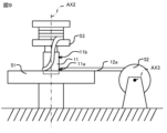
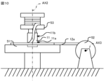
- the reactor device 1 having the above configuration is manufactured by the manufacturing method shown in FIG. 8. First, a winding process is performed in which the winding 12a is wound around the winding core 11 to generate the disk coil 12 (step S11).
- the winding table 51 is a table that can rotate around a rotation axis AX2 that extends vertically.
- the winding core 11 is attached to the central recess of the winding table 51 with the central axis AX1 aligned with the rotation axis AX2 of the winding table 51.
- the first winding drum 52 and the second winding drum 53 are pre-wound with the winding 12a to be wound around the winding core 11.
- the first winding drum 52 is rotatable around a rotation axis AX3 that extends horizontally.
- the second winding drum 53 is rotatable around a rotation axis AX2.
- a portion of the winding 12a is wound around one end of the winding 12a on the first winding drum 52, and another portion is wound around the other end of the winding 12a on the second winding drum 53. Reference positions away from both ends of the winding 12a are located adjacent to the winding core 11. In the first embodiment, the intermediate portion including the center of the winding 12a is the reference position located adjacent to the winding core 11.
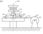
- a removable jig 54 is installed vertically above winding 12a wound around winding position 11a, as shown in FIG. 11.
- Jig 54 has a structure through which winding 12a can be inserted and which allows it to be removed from disc coil 12 after winding winding 12a around winding position 11b.
- jig 54 has semicircular ring members 54a and 54b, as shown in FIG. 12.
- FIG. 12 is a vertical view of jig 54 installed as in FIG. 11.
- the winding 12a When the winding 12a is finished being wound around the winding position 11b, the winding 12a is separated from the first winding drum 52 and the second winding drum 53, and the disk coil 12 is formed.
- a removal process is performed to remove the jig 54 from the disk coil 12 (step S12).
- the jig 54 horizontally in the state shown in Figure 13, the jig 54 sandwiched between the winding 12a wound at the winding position 11a and the winding 12a wound at the winding position 11b can be removed.
- an arrangement process is performed in which a plurality of disc coils 12 wound around corresponding winding cores 11 and a maintaining member that maintains the relative positional relationship of the plurality of disc coils 12 by abutting against the plurality of disc coils 12 (step S13).
- the second spacer 15 is sandwiched between the windings 12a.
- the disk coils 12 sandwiched between the second spacer 15 and the first spacer 14 are arranged alternately, so that the first spacer 14 is provided between the disk coils 12.
- a fixing process is performed in which the multiple disk coils 12, the multiple first spacers 14, and the multiple second spacers 15 arranged as described above are sandwiched between a pair of frames 16, and the multiple first bolts 17 supporting the multiple disk coils 12 are fixed to the pair of frames 16 (step S14).
- the multiple disk coils 12, the multiple first spacers 14, and the multiple second spacers 15 are sandwiched between a pair of frames 16 via a pair of end spacers 19.
- a first bolt 17 is inserted through two through holes formed in each of the multiple first spacers 14, the multiple second spacers 15, the pair of end spacers 19, and the pair of frames 16.
- Each first bolt 17 is fixed to each of the frames 16 by fastening a first fastening member 18.
- step S14 the reactor device 1 is assembled.
- the assembled reactor device 1 is then insulated, for example, by impregnation with varnish.
- the disk coil 12 provided in the reactor device 1 according to the first embodiment is formed of the winding 12a wound around two winding positions 11a and 11b spaced apart from each other on the winding core 11.
- the portion of the winding 12a wound around the winding position 11a and the portion of the winding 12a wound around the winding position 11b are spaced apart from each other.
- the disk coil 12 is a coil with multiple rows, it is formed from a single winding 12a, and there is no need to connect the multiple rows of coils on the radially inner side. In addition, both ends of the winding 12a are located on the radially outer side. Therefore, the manufacturing process of the reactor device 1 is simpler than a manufacturing process that includes a process of connecting the multiple rows of coils on the radially inner side.
- the structure and shape of the reactor device 1 are not limited to the above example.
- a reactor device having a structure and shape different from the reactor device 1 according to the first embodiment will be described in a second embodiment, focusing on the differences from the first embodiment.
- the reactor device 2 according to the second embodiment has four winding cores 21 arranged in the extension direction of the central axis AX1. Adjacent winding cores 21 abut against each other.
- the manufacturing method of the reactor device 2 is the same as that of the first embodiment.
- the winding core 21 which is located at the end in the extension direction of the central axis AX1, abuts against the frame 16.
- the winding core 21 has a cylindrical shape. In a cross section perpendicular to the central axis AX1, the cross-sectional area of the winding core 21 is larger than the cross-sectional area of the winding core 11 in embodiment 1. In other words, the winding core 21 is a cylinder that is thicker than the winding core 11.
- the winding core 21 is formed of an insulating material such as resin or ceramic.
- the reactor device 2 includes a suppression member 22 that suppresses movement of the multiple disk coils 12 in the extension direction of the central axis AX1 as a maintaining member that maintains the relative positional relationship between the multiple disk coils 12.
- the reactor device 2 includes a pair of suppression members 22 that sandwich the multiple disk coils 12 in the radial direction perpendicular to the central axis AX1.
- the suppressing member 22 extends in the direction of extension of the central axis AX1 and abuts against the multiple disk coils 12 to suppress deviation of the disk coils 12 in the direction of extension of the central axis AX1.
- the surface of the suppressing member 22 facing the multiple disk coils 12 is a curved surface.
- the suppressing member 22 abuts against the multiple disk coils 12 with the curved surface.
- the suppressing member 22 may be attached to the disk coils 12, for example, by a string-like attachment member 22a inserted between the wound windings 12a.
- the suppressing member 22 and the attachment member 22a are formed of an insulating material such as resin or ceramic.
- the attachment member 22a is, for example, a cable tie.
- the reactor device 2 includes a plurality of second bolts 23 that penetrate the winding core 21 in the X-axis direction and are fixed to a pair of frames 16.
- the second bolts 23 are fixed to the frames 16 by fastening second fastening members 24.
- a second bolt 23 passes through the winding cores 21 and is fixed to the frame 16, thereby fixing the relative position of the disk coil 12 wound around the winding cores 21 to the frame 16.
- the reactor device 2 maintains the relative positional relationship between the multiple disk coils 12 by the suppression member 22.
- the reactor device 2 does not have the first spacer 14 and the second spacer 15 that the reactor device 1 has. This allows more air to flow through the gaps 13 between the disk coils 12 and the gaps 12b in each disk coil 12. This results in a reactor device 2 with higher cooling performance than the reactor device 1.
- the structure of the winding core is not limited to the above example.
- a reactor device including a winding core that is a solid material will be described in a third embodiment, focusing on the differences from the second embodiment.
- the configuration of the reactor device according to the third embodiment is the same as that of the second embodiment, except for the structure of the winding core.
- the manufacturing method of the reactor device 3 is the same as that of the first embodiment.
- the winding core 31 of the reactor device 3 shown in FIG. 16 has a cylindrical magnetic body 32 extending in the extension direction of the central axis AX1, and a first insulating member 33 covering the outer peripheral surface of the magnetic body 32 around the central axis AX1.
- the magnetic body 32 is a ferromagnetic body, for example, ferrite.
- the magnetic body 32 has a cylindrical shape.
- the second bolt 23 is inserted into the magnetic body 32. As shown in FIG. 17, in which the illustration of the second bolt 23 is omitted from FIG. 16, the magnetic body 32 is formed with a first through hole 32a through which the second bolt 23 is inserted.
- the reactor device 3 further includes a second insulating member 34 that covers the wall surface of the first through hole 32a of the magnetic body 32.
- the second insulating member 34 is, for example, a resin that is applied to the wall surface of the first through hole 32a.
- the second insulating member 34 insulates the magnetic body 32 from the second bolt 23 that is inserted into the first through hole 32a.
- the first insulating member 33 is, for example, a resin applied to the outer peripheral surface of the magnetic body 32.
- the first insulating member 33 insulates the magnetic body 32 from the disk coil 12 wound around the winding core 31.
- the reactor device 3 By including the winding core 31 having the magnetic body 32 therein, the reactor device 3 exhibits characteristics similar to those of a reactor including a coil with an iron core.
- the flux linkage ⁇ of a coil changes depending on whether or not an iron core is inserted in the coil.
- the flux linkage ⁇ 0 of an air-core coil is expressed by the following formula (2)
- the flux linkage ⁇ s of a coil with an iron core is expressed by the following formula (3).
- k is a proportionality constant
- ⁇ 0 is the magnetic permeability of a vacuum
- ⁇ s is the relative magnetic permeability of the iron core.
- the reactance of the reactor device 3 which exhibits characteristics similar to those of a reactor having an iron core coil, is larger than those of the reactor devices 1 and 2.
- the reactor device 3 includes a winding core 31 having a magnetic body 32. Therefore, the winding core 31 functions as an iron core, and the reactance of the reactor device 3 is greater than that of the reactor devices 1 and 2. By using the reactor device 3 with increased reactance, it is possible to reduce the size and weight of the device.
- reactor devices 2 and 3 may include at least one of the first spacer 14 and the second spacer 15 included in reactor device 1.
- the structure of the winding core is not limited to the above example.
- the winding core 11 provided in the reactor device 1 may be formed with a second through hole 11c that penetrates in the radial direction, as shown in FIG. 18. By forming the second through hole 11c, more air can be allowed to flow between the disk coils 12, and the cooling performance of the reactor device 1 can be improved.
- the winding cores 11, 21 may be in the shape of a square tube, and the winding core 31 may be in the shape of a square column.
- the number of winding cores 11, 21, 31 is not limited to the above example, and may be any number equal to or greater than two.
- the winding core 31 may be formed by fitting a columnar magnetic body 32 into a cylindrical first insulating member 33.
- the winding core 31 may be formed by bonding a sheet-like insulating member to the outer peripheral surface of the columnar magnetic body 32, so that the first insulating member 33 is formed.
- the structure and winding method of the winding 12a are not limited to the above example.
- the winding 12a may be formed from a single wire 61, or may be formed by combining any number of wires 61 and covering them with insulating tape 64.
- the winding 12a may be wound around the winding cores 11, 21, and 31 using an edgewise method.
- the first spacer 14 is not limited to the above example, but may be made of any material that can reduce the thermal stress on the disk coil 12 by being pushed and deformed by the disk coil 12, which expands when current is applied.
- the shape and arrangement of the first spacer 14 are not limited to the above example, and may be any as long as it can abut against two adjacent disk coils 12 and guide air in the positive direction of the Z axis.
- four first spacers 14, which are plate-shaped members extending in the radial direction, may be provided in each gap 13.
- the thickness of the first spacers 14 in the extension direction of the central axis AX1 may vary depending on the position of the first spacer 14 in the extension direction of the central axis AX1.
- the thickness of the first spacer 14 located in the center in the extension direction of the central axis AX1 may be greater than the thickness of the first spacer 14 located at the end in the extension direction of the central axis AX1.
- the second spacer 15 is not limited to the above example, but may be made of any material that can reduce the thermal stress on the disk coil 12 by being pushed and deformed by the disk coil 12, which expands when current is applied.
- the shape and arrangement of the second spacers 15 are not limited to the above example, and may be any shape and arrangement as long as they can abut against the windings 12a wound around the winding positions 11a and 11b of the winding core 11 and guide air in the positive direction of the Z axis.
- four second spacers 15, which are plate-shaped members extending in the radial direction, may be provided in each gap 12b.
- the reactor device 1 may include eight first bolts 17 that pass through a plurality of first spacers 14, a plurality of second spacers 15, and a pair of end spacers 19.
- the method of attaching the first bolts 17 to the pair of frames 16 is not limited to fastening with the first fastening members 18, but may be by adhesive bonding, welding, or other attachment methods.
- the number and positions of the second bolts 23 are not limited to the above example.
- the reactor device 3 may be provided with three second bolts 23 that penetrate the winding core 31.
- the method of attaching the second bolts 23 to the pair of frames 16 is not limited to fastening with the second fastening members 24, but may be an attachment method such as gluing with an adhesive or welding.
- the reactor device 1 does not need to be provided with an end spacer 19.
- the winding core 11 located at the end in the extension direction of the central axis AX1 may abut against the frame 16.
- the winding core 11 abuts against the frame 16
- a gap is formed between the disk coil 12 located at the end and the frame 16.
- the width of the gap between the disk coil 12 and the frame 16 is longer than the insulation distance required to insulate the disk coil 12 from the frame 16.
- the number of winding cores 11 provided in the reactor device 1 may be any number greater than or equal to two. Adjacent winding cores 11 may be separated from each other.
- the number of winding cores 21 and 31 provided in each of the reactor devices 2 and 3 may be any number greater than or equal to two.
- the structure and mounting method of the suppression member 22 are not limited to the above example, and are arbitrary. As one example, as shown in FIG. 19, both ends of the suppression member 22 may abut against the frame 16. As another example, the suppression member 22 may be adhered to the multiple disk coils 12. As another example, the shape of a cross section perpendicular to the central axis AX1 of the suppression member 22 may be rectangular. As another example, the surface of the suppression member 22 facing the multiple disk coils 12 may be formed with alternating convex portions that protrude into the gap 13 and concave portions into which the disk coils 12 fit.
- the shape, structure, and mounting position of the mounting member 22a may be arbitrary as long as the suppression member 22 can be attached firmly enough to suppress movement of each disc coil 12 in the extension direction of the central axis AX1.
- the suppression member 22 may be attached to the disc coil 12 by a mounting member 22a provided for each disc coil 12.
- the manufacturing method of the reactor device 1-3 is not limited to the above example.
- varnish impregnation may be performed for each disk coil 12 wound around the winding cores 11, 21, and 31.
- the structure and shape of the jig 54 are not limited to the above example, and may be any structure and shape that allows the winding 12a to be inserted and that allows the winding 12a to be removed after winding at the winding positions 11a and 11b.
- the orientation in which the reactor device 1-3 is attached under the floor of the car body of the railway vehicle is not limited to the above example.
- the reactor device 1-3 may be attached under the floor of the car body with the Y axis oriented in the direction of the width of the railway vehicle.
- the reactor device 1-3 is not limited to being attached under the floor of the car body, and can be attached at any position on the railway vehicle.
- the reactor device 1-3 is not limited to being mounted on a railway vehicle, and can be mounted on any moving object such as a trolley bus or a tram.
- the reactor device 1-3 is not limited to being mounted on a moving object, and can be installed at any location indoors or outdoors.
Landscapes
- Engineering & Computer Science (AREA)
- Power Engineering (AREA)
- Coils Of Transformers For General Uses (AREA)
Priority Applications (2)
| Application Number | Priority Date | Filing Date | Title |
|---|---|---|---|
| PCT/JP2023/027879 WO2025027721A1 (ja) | 2023-07-28 | 2023-07-28 | リアクトル装置およびリアクトル装置の製造方法 |
| JP2025538061A JP7785249B2 (ja) | 2023-07-28 | 2023-07-28 | リアクトル装置およびリアクトル装置の製造方法 |
Applications Claiming Priority (1)
| Application Number | Priority Date | Filing Date | Title |
|---|---|---|---|
| PCT/JP2023/027879 WO2025027721A1 (ja) | 2023-07-28 | 2023-07-28 | リアクトル装置およびリアクトル装置の製造方法 |
Publications (1)
| Publication Number | Publication Date |
|---|---|
| WO2025027721A1 true WO2025027721A1 (ja) | 2025-02-06 |
Family
ID=94394643
Family Applications (1)
| Application Number | Title | Priority Date | Filing Date |
|---|---|---|---|
| PCT/JP2023/027879 Pending WO2025027721A1 (ja) | 2023-07-28 | 2023-07-28 | リアクトル装置およびリアクトル装置の製造方法 |
Country Status (2)
| Country | Link |
|---|---|
| JP (1) | JP7785249B2 (https=) |
| WO (1) | WO2025027721A1 (https=) |
Citations (12)
| Publication number | Priority date | Publication date | Assignee | Title |
|---|---|---|---|---|
| JPS5295050A (en) * | 1976-02-06 | 1977-08-10 | Hitachi Ltd | Airrcore coil |
| JPS52151351U (https=) * | 1976-05-14 | 1977-11-16 | ||
| JPS5393649U (https=) * | 1976-12-28 | 1978-07-31 | ||
| JPS55156420U (https=) * | 1979-04-27 | 1980-11-11 | ||
| JPS56110642U (https=) * | 1980-01-24 | 1981-08-27 | ||
| JPS61195028U (https=) * | 1985-05-24 | 1986-12-04 | ||
| JPH04317308A (ja) * | 1991-04-17 | 1992-11-09 | Toshiba Corp | 空心自冷式リアクトル |
| CN202454417U (zh) * | 2012-02-22 | 2012-09-26 | 明珠电气有限公司 | 干式平波电抗器 |
| WO2018116362A1 (ja) * | 2016-12-19 | 2018-06-28 | 三菱電機株式会社 | 鉄道車両用空心型リアクトル |
| WO2019008731A1 (ja) * | 2017-07-06 | 2019-01-10 | 三菱電機株式会社 | 車両用リアクトル |
| WO2019008621A1 (ja) * | 2017-07-03 | 2019-01-10 | 三菱電機株式会社 | 車両用空心型リアクトル |
| JP2020027840A (ja) * | 2018-08-10 | 2020-02-20 | 三菱電機株式会社 | リアクトル |
-
2023
- 2023-07-28 JP JP2025538061A patent/JP7785249B2/ja active Active
- 2023-07-28 WO PCT/JP2023/027879 patent/WO2025027721A1/ja active Pending
Patent Citations (12)
| Publication number | Priority date | Publication date | Assignee | Title |
|---|---|---|---|---|
| JPS5295050A (en) * | 1976-02-06 | 1977-08-10 | Hitachi Ltd | Airrcore coil |
| JPS52151351U (https=) * | 1976-05-14 | 1977-11-16 | ||
| JPS5393649U (https=) * | 1976-12-28 | 1978-07-31 | ||
| JPS55156420U (https=) * | 1979-04-27 | 1980-11-11 | ||
| JPS56110642U (https=) * | 1980-01-24 | 1981-08-27 | ||
| JPS61195028U (https=) * | 1985-05-24 | 1986-12-04 | ||
| JPH04317308A (ja) * | 1991-04-17 | 1992-11-09 | Toshiba Corp | 空心自冷式リアクトル |
| CN202454417U (zh) * | 2012-02-22 | 2012-09-26 | 明珠电气有限公司 | 干式平波电抗器 |
| WO2018116362A1 (ja) * | 2016-12-19 | 2018-06-28 | 三菱電機株式会社 | 鉄道車両用空心型リアクトル |
| WO2019008621A1 (ja) * | 2017-07-03 | 2019-01-10 | 三菱電機株式会社 | 車両用空心型リアクトル |
| WO2019008731A1 (ja) * | 2017-07-06 | 2019-01-10 | 三菱電機株式会社 | 車両用リアクトル |
| JP2020027840A (ja) * | 2018-08-10 | 2020-02-20 | 三菱電機株式会社 | リアクトル |
Also Published As
| Publication number | Publication date |
|---|---|
| JPWO2025027721A1 (https=) | 2025-02-06 |
| JP7785249B2 (ja) | 2025-12-12 |
Similar Documents
| Publication | Publication Date | Title |
|---|---|---|
| US8614617B2 (en) | Reactor | |
| US20110241455A1 (en) | Magnetic Shield for Stator Core End Structures of Electric Rotating Machine | |
| KR100208483B1 (ko) | 원통형 리니어모터 | |
| US10096420B2 (en) | Reactor | |
| CN103026435B (zh) | 电抗器装置 | |
| JP6613784B2 (ja) | 変圧器の鉄心支持構造及び鉄心支持方法 | |
| EP3116104B1 (en) | Slot insulation for electrical machines | |
| JP2012023090A (ja) | リアクトル | |
| JPWO2020121806A1 (ja) | ステータ及びそれを用いたモータ | |
| US7148593B2 (en) | Concentrated winding stator coil for an electric rotary machine | |
| JPWO2021131575A5 (https=) | ||
| JP7785249B2 (ja) | リアクトル装置およびリアクトル装置の製造方法 | |
| EP3867997B1 (en) | Electric machine structure and technology | |
| JP6333044B2 (ja) | 突極形回転子および突極形回転子の製造方法 | |
| WO2018116362A1 (ja) | 鉄道車両用空心型リアクトル | |
| JP2012023079A (ja) | リアクトル | |
| US20180358160A1 (en) | Stationary Induction Apparatus | |
| JP7335852B2 (ja) | 突極形回転子および突極形回転電機 | |
| AU2019202480B2 (en) | Stator of rotating electrical machine and method of manufacturing stator of rotating electrical machine | |
| WO2018062117A1 (ja) | 非接触給電用コイルユニット | |
| JPWO2025027721A5 (https=) | ||
| KR20230081518A (ko) | 토로이달 모터용 이분할 코어 고정자 어셈블리와 이를 이용한 와인딩 공법 | |
| KR102857334B1 (ko) | 냉각 구조가 구비된 일체형 코어를 포함하는 리액터 | |
| US20260058514A1 (en) | Coil system for a superconducting motor | |
| JP2015089162A (ja) | 回転電機ステータ |
Legal Events
| Date | Code | Title | Description |
|---|---|---|---|
| 121 | Ep: the epo has been informed by wipo that ep was designated in this application |
Ref document number: 23947520 Country of ref document: EP Kind code of ref document: A1 |
|
| ENP | Entry into the national phase |
Ref document number: 2025538061 Country of ref document: JP Kind code of ref document: A |
|
| WWE | Wipo information: entry into national phase |
Ref document number: 2025538061 Country of ref document: JP |
|
| NENP | Non-entry into the national phase |
Ref country code: DE |