WO2025027676A1 - フィルタ装備体、発泡成形体の製造装置および製造方法 - Google Patents
フィルタ装備体、発泡成形体の製造装置および製造方法 Download PDFInfo
- Publication number
- WO2025027676A1 WO2025027676A1 PCT/JP2023/027727 JP2023027727W WO2025027676A1 WO 2025027676 A1 WO2025027676 A1 WO 2025027676A1 JP 2023027727 W JP2023027727 W JP 2023027727W WO 2025027676 A1 WO2025027676 A1 WO 2025027676A1
- Authority
- WO
- WIPO (PCT)
- Prior art keywords
- foaming agent
- molten resin
- physical foaming
- introduction
- filter
- Prior art date
- Legal status (The legal status is an assumption and is not a legal conclusion. Google has not performed a legal analysis and makes no representation as to the accuracy of the status listed.)
- Ceased
Links
Images

Classifications
-
- B—PERFORMING OPERATIONS; TRANSPORTING
- B29—WORKING OF PLASTICS; WORKING OF SUBSTANCES IN A PLASTIC STATE IN GENERAL
- B29C—SHAPING OR JOINING OF PLASTICS; SHAPING OF MATERIAL IN A PLASTIC STATE, NOT OTHERWISE PROVIDED FOR; AFTER-TREATMENT OF THE SHAPED PRODUCTS, e.g. REPAIRING
- B29C44/00—Shaping by internal pressure generated in the material, e.g. swelling or foaming ; Producing porous or cellular expanded plastics articles
- B29C44/34—Auxiliary operations
- B29C44/3442—Mixing, kneading or conveying the foamable material
- B29C44/3446—Feeding the blowing agent
-
- B—PERFORMING OPERATIONS; TRANSPORTING
- B29—WORKING OF PLASTICS; WORKING OF SUBSTANCES IN A PLASTIC STATE IN GENERAL
- B29C—SHAPING OR JOINING OF PLASTICS; SHAPING OF MATERIAL IN A PLASTIC STATE, NOT OTHERWISE PROVIDED FOR; AFTER-TREATMENT OF THE SHAPED PRODUCTS, e.g. REPAIRING
- B29C44/00—Shaping by internal pressure generated in the material, e.g. swelling or foaming ; Producing porous or cellular expanded plastics articles
-
- B—PERFORMING OPERATIONS; TRANSPORTING
- B29—WORKING OF PLASTICS; WORKING OF SUBSTANCES IN A PLASTIC STATE IN GENERAL
- B29C—SHAPING OR JOINING OF PLASTICS; SHAPING OF MATERIAL IN A PLASTIC STATE, NOT OTHERWISE PROVIDED FOR; AFTER-TREATMENT OF THE SHAPED PRODUCTS, e.g. REPAIRING
- B29C44/00—Shaping by internal pressure generated in the material, e.g. swelling or foaming ; Producing porous or cellular expanded plastics articles
- B29C44/34—Auxiliary operations
- B29C44/36—Feeding the material to be shaped
-
- B—PERFORMING OPERATIONS; TRANSPORTING
- B29—WORKING OF PLASTICS; WORKING OF SUBSTANCES IN A PLASTIC STATE IN GENERAL
- B29C—SHAPING OR JOINING OF PLASTICS; SHAPING OF MATERIAL IN A PLASTIC STATE, NOT OTHERWISE PROVIDED FOR; AFTER-TREATMENT OF THE SHAPED PRODUCTS, e.g. REPAIRING
- B29C44/00—Shaping by internal pressure generated in the material, e.g. swelling or foaming ; Producing porous or cellular expanded plastics articles
- B29C44/34—Auxiliary operations
- B29C44/36—Feeding the material to be shaped
- B29C44/38—Feeding the material to be shaped into a closed space, i.e. to make articles of definite length
- B29C44/42—Feeding the material to be shaped into a closed space, i.e. to make articles of definite length using pressure difference, e.g. by injection or by vacuum
-
- B—PERFORMING OPERATIONS; TRANSPORTING
- B29—WORKING OF PLASTICS; WORKING OF SUBSTANCES IN A PLASTIC STATE IN GENERAL
- B29C—SHAPING OR JOINING OF PLASTICS; SHAPING OF MATERIAL IN A PLASTIC STATE, NOT OTHERWISE PROVIDED FOR; AFTER-TREATMENT OF THE SHAPED PRODUCTS, e.g. REPAIRING
- B29C45/00—Injection moulding, i.e. forcing the required volume of moulding material through a nozzle into a closed mould; Apparatus therefor
-
- B—PERFORMING OPERATIONS; TRANSPORTING
- B29—WORKING OF PLASTICS; WORKING OF SUBSTANCES IN A PLASTIC STATE IN GENERAL
- B29C—SHAPING OR JOINING OF PLASTICS; SHAPING OF MATERIAL IN A PLASTIC STATE, NOT OTHERWISE PROVIDED FOR; AFTER-TREATMENT OF THE SHAPED PRODUCTS, e.g. REPAIRING
- B29C45/00—Injection moulding, i.e. forcing the required volume of moulding material through a nozzle into a closed mould; Apparatus therefor
- B29C45/17—Component parts, details or accessories; Auxiliary operations
- B29C45/46—Means for plasticising or homogenising the moulding material or forcing it into the mould
Definitions
- Patent Document 1 discloses a method for molding a foam molded body using nitrogen or carbon dioxide, which are relatively low pressure, without the need for a supercritical fluid. With this method, fine foam cells can be formed in the molded body through a simple process using a low-pressure physical foaming agent without using special high-pressure equipment.
- the molten resin in the starvation zone may flow back into the inlet for introducing the physical foaming agent, which is provided in the cylinder and opens into the starvation zone, resulting in a vent-up.
- the molten resin may solidify and remain in the inlet. If the resin remains in the inlet, the physical foaming agent cannot be supplied stably, so it is necessary to remove the remaining resin, which is time-consuming.
- the gas (physical foaming agent) accumulated in the introduction rate adjusting container is introduced into the plasticizing cylinder all at once, which may result in a loud foaming sound.
- the present invention was made in consideration of the above circumstances, and aims to provide a filter-equipped body, a foam molding manufacturing device, and a manufacturing method that can optimize the amount of molten resin supplied while visually checking the plasticization state of the molten resin in the starvation zone, and can prevent the molten resin from flowing back into the introduction container and solidifying due to venting up, etc.
- the present invention provides a filter-equipped body that is detachably provided in a cylindrical introduction vessel that introduces a physical foaming agent into a molten resin in a starved state, comprising:
- the present invention comprises a cylindrical filter holding member and a filter for introducing a physical foaming agent held at a tip of the filter holding member,
- the filter holding member is characterized in that it is provided, on its outer periphery, with a sliding member that enables the filter holding member to slide along the inner periphery of the introduction container in the axial direction of the introduction container.
- the filter for introducing a physical foaming agent has, for example, a filter body and a plurality of fine holes provided in the filter body so as to penetrate the filter body in the thickness direction.
- the fine holes may be formed in a straight shape in the thickness direction of the filter body, or may be formed as follows. That is, the micropores include resin contact side holes that open on one surface side of the filter body and are in contact with the molten resin, and physical foaming agent introduction holes that open on the other surface side of the filter body and communicate with the resin contact side holes, through which the physical foaming agent is introduced, and the resin contact side holes may have a diameter that is equal to or smaller than the diameter of the physical foaming agent introduction holes and is 10 to 80 ⁇ m.
- the filter holding member that holds the filter for introducing a physical foaming agent is provided with a sliding member on its outer periphery that allows it to slide on the inner peripheral surface of the introduction container in the axial direction of the introduction container, so that when optimizing the supply amount of resin while visually checking the plasticization state of the molten resin in the starvation zone, the operator grasps the filter holding member and pulls it out in the axial direction of the introduction container, whereby the filter holding member slides on the inner peripheral surface of the introduction container in the axial direction by the sliding member, and the filter holding member can be removed from the introduction container. This allows the starvation zone to be visually checked through the introduction port.
- the supply amount of molten resin can be optimized while visually checking the plasticization state of the molten resin in the starvation zone.
- the filter for introducing a physical foaming agent can be provided at the inlet by grasping the filter holding member holding the filter for introducing a physical foaming agent and inserting it into the introduction container, thereby preventing the molten resin from flowing back into the introduction container and becoming stuck there due to venting up, for example.
- the sliding member may be a ball retainer provided on the outer periphery of the filter holding member.
- a ball retainer is provided on the outer periphery of the filter holding member as a sliding member, so the filter holding member can be easily and reliably inserted and removed from the introduction container in the axial direction.
- the outer diameter of the tip of the filter holding member may be set so that the gap between the outer peripheral surface of the tip and the inner peripheral surface of the tip of the introduction container is 50 ⁇ m or less.
- the gap between the outer peripheral surface of the tip of the filter holding member and the inner peripheral surface of the tip of the introduction container is narrow, at 50 ⁇ m or less, so that the starved molten resin can be prevented from entering the introduction container through the gap.
- the manufacturing apparatus for foamed molded articles of the present invention includes a plasticization zone in which a thermoplastic resin is plasticized and melted to become a molten resin, and a starvation zone in which the molten resin is in a starvation state, and includes a plasticization cylinder provided with an inlet for introducing a physical foaming agent into the starvation zone; An introduction container connected to the introduction port; a physical foaming agent supply mechanism connected to the introduction container and supplying a physical foaming agent to the plasticizing cylinder via the introduction container;
- the introduction container is provided with the filter-equipped body, Supplying a pressurized fluid containing the physical foaming agent at a constant pressure to the introduction vessel, and introducing the pressurized fluid at the constant pressure from the introduction vessel to the starvation zone to maintain the starvation zone at the constant pressure; While maintaining the starvation zone at the constant pressure, the molten resin in the starved state is brought into contact with a pressurized fluid containing a physical foaming agent at the constant
- the method for producing a foamed molded article of the present invention includes a plasticization cylinder having a plasticization zone in which a thermoplastic resin is plasticized and melted to become a molten resin, and a starvation zone in which the molten resin is in a starvation state, the plasticization cylinder being provided with an inlet for introducing a physical foaming agent into the starvation zone; an introduction container connected to the introduction port; a production apparatus having the filter-equipped body provided in the introduction vessel,
- the manufacturing method includes: In the plasticization zone, the thermoplastic resin is plasticized and melted to form the molten resin; supplying a pressurized fluid containing the physical foaming agent at a constant pressure to the introduction vessel, and introducing the pressurized fluid at the constant pressure from the introduction vessel to the starvation zone to maintain the starvation zone at the constant pressure; starving the molten resin in the starvation zone; contacting the starved molten resin with the pressurized fluid in the starvation zone while maintaining
- the filter holding member of the filter-equipped body is provided on its outer periphery with a sliding member that allows the filter holding member to slide on the inner periphery of the introduction container in the axial direction of the introduction container, so that when optimizing the supply amount of resin while visually checking the plasticization state of the molten resin in the starvation zone, the operator can grasp the filter holding member and pull it out in the axial direction of the introduction container, whereby the filter holding member slides on the inner periphery of the introduction container in the axial direction by the sliding member, and the filter holding member can be removed from the introduction container.
- the supply amount of resin can be optimized while visually checking the plasticization state of the molten resin in the starvation zone.
- a filter holding member holding a filter for introducing a physical foaming agent can be inserted into the introduction container to prevent the molten resin from flowing back into the introduction container and solidifying due to venting up, for example.
- the present invention makes it possible to optimize the amount of resin supplied while visually checking the plasticization state of the molten resin in the starvation zone, and also prevents the molten resin from flowing back into the introduction container and solidifying by venting up, etc.
- FIG. 1 is a schematic cross-sectional view of an extrusion manufacturing apparatus for foamed molded articles, showing an embodiment of the present invention.
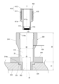
- FIG. 4 is a schematic cross-sectional view showing the introduction container according to the first embodiment with the filter-equipped body removed.
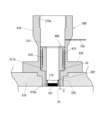
- FIG. 4 is a schematic cross-sectional view showing a state in which a filter-equipped body is inserted into the introduction container according to the first embodiment.
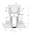
- FIG. 2 is a schematic cross-sectional view showing a state in which a filter-equipped body is inserted into an introduction container and a lid is closed.
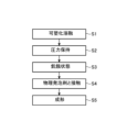
- 3 is a flowchart showing the extrusion manufacturing method for the foam molded article according to the first embodiment.
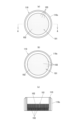
- FIG. 1A shows a filter for introducing a physical foaming agent, in which (a) is a plan view, (b) is a bottom view, and (c) is a cross-sectional view taken along line AA in (a).
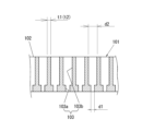
- FIG. 2 is a cross-sectional view of a main part of the filter for introducing a physical foaming agent according to the first embodiment.
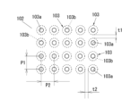
- FIG. 2 is a bottom view of a main part of the filter for introducing a physical foaming agent according to the first embodiment.
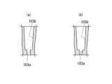
- 10A is a cross-sectional view of a first modified example
- FIG. 10B is a cross-sectional view of a second modified example, showing deformations of the microholes according to the first embodiment.
- FIG. 13 is a bottom view of a main part of a modified example of the filter for introducing a physical foaming agent according to the first embodiment.
- a foamed molded article is manufactured using a manufacturing apparatus 1000 shown in Fig. 1.
- the manufacturing apparatus 1000 mainly includes a plasticizing cylinder 210 having a screw 20 installed therein, a cylinder 100 which is a physical foaming agent supply mechanism that supplies a physical foaming agent to the plasticizing cylinder 210, a mold clamping unit (not shown) having a mold, and a control device (not shown) for controlling the operation of the plasticizing cylinder 210 and the mold clamping unit.
- the molten resin that has been plasticized and melted in the plasticizing cylinder 210 flows from the right to the left in Fig. 1. Therefore, within the plasticizing cylinder 210 of this embodiment, the right side in Fig. 1 is defined as the "upstream” or "rear” and the left side is defined as the "downstream" or "front”.
- the plasticizing cylinder 210 has a plasticizing zone 21 where the thermoplastic resin is plasticized and melted to become a molten resin, and a starvation zone 23 downstream of the plasticizing zone 21 where the molten resin becomes in a starved state.
- the "starvation state” refers to a state in which the molten resin does not fill the starvation zone 23, but is not filled therewith. Therefore, there is space in the starvation zone 23 other than the portion occupied by the molten resin.
- the plasticizing cylinder 210 is also formed with an inlet 202 for introducing a physical foaming agent into the starvation zone 23, and an introduction rate adjusting container (introduction container, pressure adjusting container) 300 is connected to the inlet 202.
- the cylinder 100 supplies the physical foaming agent to the plasticizing cylinder 210 via the introduction rate adjusting container 300.
- the manufacturing apparatus 1000 has only one starvation zone 23, the manufacturing apparatus used in this embodiment is not limited to this.
- the manufacturing apparatus may have a plurality of starvation zones 23 and inlets 202 formed therein, and the physical foaming agent may be introduced into the plasticizing cylinder 210 from the plurality of inlets 202.
- the manufacturing apparatus 1000 is an injection molding apparatus, the manufacturing apparatus used in this embodiment is not limited to this and may be, for example, an extrusion molding apparatus.
- the resin pellets are plasticized and melted by the rotation of the screw 20 in the plasticizing cylinder 210, and the molten resin is sent to the front side in the plasticizing cylinder 210.
- the molten resin is sent to the front side in the plasticizing cylinder 210 by the rotation of the screw 20.
- On the upper side of the plasticizing cylinder 210 there are provided, from the upstream side, a resin supply port 201 for supplying thermoplastic resin to the cylinder 210, and an inlet 202 for introducing a physical foaming agent into the plasticizing cylinder 210.
- a hopper 211 for supplying resin and a feed screw 212 are disposed, and at the introduction port 202, an introduction speed adjusting container 300 is connected.
- the plasticizing cylinder 210 has a plasticizing zone 21 provided on the upstream side and a starvation zone 23 provided on the downstream side.
- the plasticizing zone 21 is a zone where the thermoplastic resin is plasticized and melted to become molten resin.
- the starvation zone 23 is a zone where the molten resin is in a starved state.
- the "starvation state” refers to a state in which the molten resin does not fill the starvation zone 23 but is not filled therewith, or a state in which the density of the molten resin has decreased. Therefore, there may be space in the starvation zone 23 other than the portion occupied by the molten resin.
- the plasticizing cylinder 210 has, from the upstream side to the downstream side, a plasticizing zone 21, a compression zone 22, a flow speed adjustment zone 25, a starvation zone 23, and a recompression zone 24.
- the plasticizing zone 21 is a zone where the thermoplastic resin is plasticized and melted to become a molten resin.
- the compression zone 22 is a zone where the thermoplastic resin is shear kneaded, plasticized and melted, and the molten resin is compressed.
- the starvation zone 23 is a zone where the molten resin becomes starved.
- the recompression zone 24 is a zone where the molten resin is recompressed.
- the flow speed adjustment zone 25 will be described later.
- the plasticizing cylinder 210 is provided with the inlet 202 as an opening for introducing the physical foaming agent into the starvation zone 23.
- the inlet 202 is connected to an introduction rate adjusting container 300 (hereinafter, sometimes referred to as the introduction container 300).
- the cylinder 100 is connected to the introduction container 300 by a pipe 154 via a pressure reducing valve 151, a pressure gauge 152, and a release valve 153.
- the cylinder 100 supplies the physical foaming agent into the cylinder 210 via the introduction container 300.
- a shutoff valve 28 that opens and closes by driving an air cylinder is provided at a nozzle tip 29 of the plasticizing cylinder 210, and high pressure can be maintained inside the plasticizing cylinder 210.
- a mold (not shown) is in close contact with the nozzle tip 29, and molten resin is injected from the nozzle tip 29 to fill a cavity formed by the mold.
- thermoplastic resin is plasticized and melted.
- the thermoplastic resin is plasticized and melted to form a molten resin (step S1 in FIG. 5).
- the thermoplastic resin various resins can be used depending on the desired heat resistance and the application of the molded body.
- thermoplastic resins such as polypropylene, polymethyl methacrylate, polyamide, polyethylene, polycarbonate, polybutylene terephthalate, amorphous polyolefin, polyetherimide, polyethylene terephthalate, polyether ether ketone, ABS resin (acrylonitrile-butadiene-styrene copolymer resin), polyphenylene sulfide, syndiotactic polystyrene, polyamide imide, polylactic acid, polycaprolactone, and composite materials thereof can be used. Crystalline resins are particularly preferable because they are easy to form fine cells. These thermoplastic resins may be used alone or in combination of two or more types.
- thermoplastic resins may be mixed with various inorganic fillers such as glass fiber, talc, carbon fiber, and ceramic, and organic fillers such as cellulose nanofiber, cellulose, and wood flour.
- the thermoplastic resin is preferably mixed with an inorganic filler or organic filler that functions as a foaming nucleating agent, or an additive that increases melt tension. By mixing these, the foam cells can be made fine.
- the thermoplastic resin may also contain various other general-purpose additives as necessary.
- thermoplastic resin is plasticized and melted in the plasticizing cylinder 210 in which the screw 20 is installed.
- a band heater (not shown) is arranged on the outer wall surface of the plasticizing cylinder 210, which heats the plasticizing cylinder 210. Furthermore, shear heat is generated by the rotation of the screw 20, which causes the thermoplastic resin to plasticize and melt.
- a pressurized fluid is used as the physical foaming agent.
- "fluid” means any of liquid, gas, and supercritical fluid.
- carbon dioxide, nitrogen, and the like are preferable as the physical foaming agent. Since the pressure of the physical foaming agent in this embodiment is relatively low, for example, a fluid that is decompressed to a constant pressure by a pressure reducing valve 151 and taken out from a cylinder 100 in which a fluid such as a nitrogen cylinder, carbon dioxide cylinder, or air cylinder is stored can be used. In this case, a pressure boosting device is not required, so the cost of the entire manufacturing device can be reduced.
- a fluid that has been pressurized to a predetermined pressure may be used as the physical foaming agent.
- the physical foaming agent can be generated by the following method. First, atmospheric air is compressed by a compressor and passed through a nitrogen separation membrane to purify the nitrogen. Next, the purified nitrogen is pressurized to a predetermined pressure using a booster pump, a syringe pump, or the like to generate the physical foaming agent. Compressed air may also be used as the physical foaming agent. In this embodiment, forced shear mixing of the physical foaming agent and the molten resin is not performed. Therefore, even if compressed air is used as a physical foaming agent, oxygen, which has low solubility in molten resin, is less likely to dissolve in the molten resin, and oxidation deterioration of the molten resin can be suppressed.
- the pressure of the physical foaming agent introduced into the starvation zone 23 is constant, and the pressure of the starvation zone 23 is maintained at the same constant pressure as the physical foaming agent introduced.
- the pressure of this physical foaming agent is preferably 0.5 MPa to 30 MPa, more preferably 1 MPa to 25 MPa, and even more preferably 1 MPa to 15 MPa.
- the optimal pressure varies depending on the type of molten resin, by setting the pressure of the physical foaming agent to 1 MPa or more, the amount of physical foaming agent required for foaming can be permeated into the molten resin, and by setting the pressure to 30 MPa or less, the heat resistance of the foamed molded article can be improved.
- the pressure of the physical foaming agent pressurizing the molten resin is "constant" means that the fluctuation range of the pressure relative to a predetermined pressure is preferably within ⁇ 20%, more preferably within ⁇ 10%.
- the pressure in the starvation zone 23 is measured, for example, by a pressure sensor 27 provided at a position opposite the inlet 202 of the plasticizing cylinder 210.
- the pressure sensor 27 shown in FIG. 1 is provided at a position that is always within the starvation zone 23 at the most advanced position and the most retreated position of the starvation zone 23.
- the position facing the inlet 202 is always within the starvation zone 23. Therefore, although the pressure sensor 27 is not provided at a position facing the inlet 202, the pressure indicated by the pressure sensor 27 and the pressure at the position facing the inlet 202 are almost the same.
- the physical foaming agent inside the introduction container 300 is heated, the temperature difference between the physical foaming agent and the molten resin is reduced, the temperature of the molten resin in contact with the physical foaming agent is prevented from being extremely lowered, and the amount of the physical foaming agent dissolved (permeated) into the molten resin is stabilized.
- the introduction container 300 functions as a buffer container with a function of heating the physical foaming agent.
- the volume of the introduction container 300 is too large, the cost of the entire device increases.
- the introduction container 300 has a structure in which the first straight section 31, which is a cylinder having a small inner diameter D1, and the second straight section 32, which is a cylinder having a large inner diameter D2, are arranged so that their central axes are aligned on the same straight line m, and a step surface 33 perpendicular to the straight line m is provided at the boundary between the second straight section 32 and the first straight section 31.
- the extension direction of the straight line m that coincides with the central axis of the first straight section 31 and the second straight section 32 coincides with the extension direction of the cylindrical introduction container 300.
- the first straight section 31 and the step surface 33 are formed by the connecting section 320
- the second straight section 32 is formed by the container body 310.
- the rotation speeds of the feed screw 212 and the screw 20, etc. are optimized, and it is confirmed whether a stable starvation state is created in the starvation zone 23. At the same time, it is confirmed whether the molten resin bulges out from the inlet 202 into the introduction container 300.
- the lid 340 can be opened and closed in a simple manner without using bolts, and that the filter-equipped body 400 described later can be removed from the introduction container 300 to remove the resin that has entered the introduction container 300.
- the material constituting the introduction container 300 is preferably pressure resistant from the viewpoint of containing pressurized fluid, and from the viewpoint of promoting solidification of the molten resin on the wall surface and suppressing the intrusion of the molten resin into the container, it is preferable that the material has a large heat capacity, is less likely to increase in temperature, and is easy to remove heat from the attached resin. Furthermore, from the viewpoint of heating the physical foaming agent, it is preferable that the material has a high thermal conductivity and is easy to transfer heat from the container body 310. From these viewpoints, the introduction container 300 is preferably made of a metal such as stainless steel (SUS).
- SUS stainless steel
- the large diameter portion 20A and the seal portion 26 reduce the clearance between the inner wall of the plasticization cylinder 210 and the screw 20 by increasing the diameter of the shaft of the screw 20, and the amount of resin supplied downstream can be reduced, so that the flow resistance of the molten resin can be increased. Therefore, in this embodiment, the large diameter portion 20A and the seal portion 26 are a mechanism for increasing the flow resistance of the molten resin.
- the seal portion 26 also has the effect of suppressing the backflow of the physical foaming agent, that is, the movement of the physical foaming agent from the downstream side to the upstream side of the seal portion 26 .
- the screw 20 Due to the presence of the large diameter portion 20A and the seal portion 26, the resin flow rate supplied from the compression zone 22 to the starvation zone 23 decreases, the molten resin is compressed in the upstream compression zone 22 and the pressure increases, and the molten resin is not filled (starved) in the downstream starvation zone 23.
- the screw 20 has a structure in which the shaft diameter of the portion located in the starvation zone 23 is smaller (thinner) and the screw flight is deeper than the portion located in the compression zone 22.
- the screw 20 has a structure in which the shaft diameter of the portion located in the starvation zone 23 is smaller (thinner) and the screw flight is deeper than the portion located in the compression zone 22. Furthermore, it is preferable that the shaft diameter and the depth of the screw flight of the screw 20 are approximately constant throughout the starvation zone 23. This allows the pressure in the starvation zone 23 to be kept approximately constant, stabilizing the starvation state of the molten resin.
- the starvation zone 23 is formed in a portion of the screw 20 where the diameter of the axis of the screw 20 and the depth of the screw flights are constant, as shown in FIG.
- the mechanism for increasing the flow resistance of the molten resin may be provided on the screw as a separate member such as a ring, or may be provided integrally with the screw as part of the screw structure. If the mechanism for increasing the flow resistance of the molten resin is provided as a separate member such as a ring, the size of the clearance portion, which is the flow path for the molten resin, can be changed by changing the ring, which has the advantage that the magnitude of the flow resistance of the molten resin can be easily changed.
- the molten resin can also be starved in the starvation zone 23 by providing a backflow prevention mechanism (sealing mechanism) between the compression zone 22 and the starvation zone 23 to prevent the molten resin from flowing back from the starvation zone 23 to the upstream compression zone 22.
- a backflow prevention mechanism such as a ring or steel ball that can move upstream due to the pressure of the physical foaming agent can be used.
- the backflow prevention mechanism requires a drive unit, there is a risk of resin stagnation. For this reason, a mechanism for increasing flow resistance that does not have a drive unit is preferable.
- the amount of thermoplastic resin supplied to the plasticizing cylinder 210 may be controlled to stabilize the starvation state of the molten resin in the starvation zone 23. If the amount of thermoplastic resin supplied is too large, it becomes difficult to maintain the starvation state.
- a general-purpose feed screw 212 is used to control the amount of thermoplastic resin supplied. By limiting the amount of thermoplastic resin supplied, the metering speed of the molten resin in the starvation zone 23 becomes greater than the plasticization speed in the compression zone 22. As a result, the density of the molten resin in the starvation zone 23 is stably reduced, and the penetration of the physical foaming agent into the molten resin is promoted.
- the length of the starvation zone 23 in the flow direction of the molten resin is preferably long to ensure the contact area and contact time between the molten resin and the physical foaming agent, but if it is too long, it will have the disadvantage of increasing the molding cycle and screw length.
- the length of the starvation zone 23 is preferably 2 to 12 times the inner diameter of the plasticizing cylinder 210, and more preferably 4 to 10 times.
- the length of the starvation zone 23 covers the entire range of the metering stroke in injection molding. In other words, it is preferable that the length of the starvation zone 23 in the flow direction of the molten resin is equal to or longer than the length of the metering stroke in injection molding.
- a predetermined amount of high-pressure physical foaming agent was forcibly introduced into the plasticizing cylinder within a predetermined time. Therefore, it is necessary to pressurize the physical foaming agent to a high pressure and accurately control the amount and time of introduction into the molten resin, and the physical foaming agent is in contact with the molten resin only for a short introduction time.
- the physical foaming agent is not forcibly introduced into the plasticizing cylinder 210, but a constant pressure physical foaming agent is continuously supplied into the plasticizing cylinder so that the pressure in the starvation zone 23 is constant, and the physical foaming agent is continuously brought into contact with the molten resin.
- the manufacturing method of this embodiment does not require control of the amount and time of introduction of the physical foaming agent, and therefore does not require check valves, solenoid valves, or other actuating valves, or control mechanisms for controlling these, reducing equipment costs.
- the physical foaming agent used in this embodiment has a lower pressure than conventional physical foaming agents, so the load on the equipment is also smaller.
- One cycle of injection molding is performed in a state where the molten resin and the physical foaming agent at a constant pressure are always present and in contact with each other, i.e., in a state where the molten resin is always pressurized by the physical foaming agent at a constant pressure in the plasticizing cylinder, one cycle of injection molding is performed, which includes a plasticization metering step, an injection step, a molding cooling step, an ejection step, etc.
- molding is performed in a state where the molten resin and the physical foaming agent at a constant pressure are always present and in contact with each other in the plasticizing cylinder, i.e., in a state where the molten resin is always pressurized by the physical foaming agent at a constant pressure in the plasticizing cylinder.
- the molten resin in contact with the physical foaming agent is molded into a foam molded body (step S5 in FIG. 5).
- the plasticizing cylinder 210 used in this embodiment is disposed downstream of the starvation zone 23 and adjacent to the starvation zone 23, and has a recompression zone 24 in which the molten resin is compressed and the pressure increases.
- the molten resin in the starvation zone 23 is caused to flow into the recompression zone 24 by the rotation of the plasticizing screw 20.
- the molten resin containing the physical foaming agent is pressure-adjusted in the recompression zone 24, and is extruded forward of the plasticizing screw 20 and metered.
- the internal pressure of the molten resin extruded forward of the plasticizing screw 20 is controlled as a screw back pressure by a hydraulic motor or an electric motor (not shown) connected to the rear of the plasticizing screw 20.
- a hydraulic motor or an electric motor not shown
- the internal pressure of the molten resin extruded forward of the plasticizing screw 20 i.e., the screw back pressure
- it is preferable to control the internal pressure of the molten resin extruded forward of the plasticizing screw 20, i.e., the screw back pressure to be about 1 to 6 MPa higher than the pressure in the starvation zone 23, which is kept constant.
- a check ring 50 is provided at the tip of the screw 20 so that the compressed resin in front of the screw 20 does not flow back upstream. As a result, the pressure in the starvation zone 23 is not affected by the resin pressure in front of the screw 20 during metering.
- the method of molding the foamed molded body is not particularly limited, and the molded body can be molded by, for example, injection foam molding, extrusion foam molding, foam blow molding, etc.
- injection foam molding is performed by injecting and filling a measured amount of molten resin from the plasticizing cylinder 210 shown in FIG. 1 into a cavity (not shown) in a mold.
- a short shot method may be used in which the mold cavity is filled with molten resin at a filling volume of 75% to 95% of the mold cavity volume, and the mold cavity is filled while the bubbles expand, or a core back method may be used in which the cavity volume is expanded and foamed after filling with molten resin at a filling volume of 100% of the mold cavity volume. Since the obtained foamed molded body has foam cells inside, the shrinkage of the thermoplastic resin during cooling is suppressed, sink marks and warpage are reduced, and a molded body with a low specific gravity is obtained.
- the molten resin in a starved state is brought into contact with the physical foaming agent at a constant pressure in the starvation zone 23 while the starvation zone 23 is maintained at a constant pressure. This makes it possible to stabilize the amount of physical foaming agent dissolved (penetrated) into the molten resin by a simple mechanism.
- the manufacturing apparatus 1000 of this embodiment includes a filter-equipped body 400.
- the filter-equipped body 400 is detachably provided in the introduction container 300.
- the filter-equipped body 400 includes a cylindrical filter holding member 410 and a filter 101 for introducing a physical foaming agent (hereinafter, sometimes abbreviated to filter 101) held at the tip of the filter holding member 410.
- the filter holding member 410 includes a cylindrical main body 411 and a donut-shaped disk-shaped flange 412 fixed to the upper end of the main body 411. An operator can grasp the filter-equipped body 400 by grasping the flange 412.
- the main body 411 has a straight hole 411a formed therein, and the filter 101 is provided at the lower end of the hole 411a.
- the filter 101 is fitted into the folder 110.
- the filter 101 is formed in a disk shape with a thickness of about 2 to 3 mm and a diameter of about 30 mm.
- the folder 110 is formed in a cylindrical shape, and the filter 101 is fitted and fixed to the inner peripheral surface of approximately the lower half of the folder 110.
- the lower end surface of the filter 101 and the lower end surface of the folder 110 are approximately flush with each other.
- a male thread portion 110c is formed on the outer peripheral surface of the folder 110, and this male thread portion 110c is screwed into a female thread portion formed on the inner peripheral surface of the lower end portion of the main body portion 411 of the filter holding member 410.
- the folder 110 is attached to the lower end portion of the main body portion 411 of the filter holding member 410. Therefore, the filter 101 is attached to the lower end portion of the main body portion 411 via the folder 110.
- a sliding member 415 that allows the inner peripheral surface of the introduction container 300 to slide in the axial direction of the introduction container 300 is provided on the outer periphery of the upper part of the main body 411 of the filter-equipped body 400.
- This sliding member 415 is a ball retainer 415 provided on the outer periphery of the main body 411. As shown in Fig. 3, when the filter-equipped body 400 is inserted into the introduction container 300, this ball retainer 415 abuts or presses against the inner peripheral surface of the introduction container 300 with almost no gap, and in this state, the multiple balls of the ball retainer 415 are able to roll on the inner peripheral surface of the introduction container 300 in the axial and circumferential directions of the introduction container 300.
- a flange portion 411 b is provided on the outer periphery of the main body portion 411 lower end side than the sliding member (ball retainer) 415 so as to protrude radially outward from the outer periphery of the main body portion 411 .
- the filter-equipped body 400 equipped with the filter 101 is inserted into the introduction container 300 from the upper end opening, and the flange portion 411b of the filter-equipped body 400 abuts against the step surface 33 of the introduction container 300, whereby the filter-equipped body 400 is axially positioned in the introduction container 300.
- the lower end surface of the filter 101 and the lower end surface of the introduction port 202 of the plasticizing cylinder 210 are flush with each other, so that the filter 101 faces the starvation zone 23 of the plasticizing cylinder 210.
- the outer diameter of the tip 410a of the filter holding member 410 of the filter-equipped body 400 is set so that the gap S between the outer circumferential surface of the tip 410a and the inner circumferential surface of the tip of the introduction container 300 is 50 ⁇ m or less.
- the tip 410a of the filter holding member 410 is inserted inside the connecting portion 320 of the tip of the introduction container 300, but the filter-equipped body 400 needs to be removed from the introduction container 300 as necessary.
- a predetermined gap S is provided between the outer circumferential surface of the tip 410a of the filter holding member 410 and the inner circumferential surface of the connecting portion 320 of the introduction container 300, and this gap S is set to 50 ⁇ m or less.
- the filter 101 has a disk-shaped filter body 102 and a large number (plurality of) fine holes 103 that penetrate the filter body 102 in the thickness direction.
- the micropores 103 are provided with a resin contact side hole 103a which opens onto one surface side of the filter body 102 and comes into contact with the molten resin, and a physical foaming agent introduction hole 103b which opens onto the other surface side of the filter body 102 and is connected to the resin contact side hole 103a, through which a physical foaming agent is introduced.
- the filter 101 is formed from a finely perforated porous metal material manufactured using a metal 3D printer. That is, one method for manufacturing three-dimensional objects in a three-dimensional modeling device that produces three-dimensional objects made of metal, a so-called metal 3D printer, is a metal powder additive manufacturing method in which metal material powder is evenly scattered to form a powder layer, and a laser beam or an electron beam is irradiated onto a specified irradiation area on the powder layer to melt and solidify the material powder in the specified irradiation area, and the process is repeated to stack sintered layers to generate the three-dimensional object.
- a metal 3D printer is a metal powder additive manufacturing method in which metal material powder is evenly scattered to form a powder layer, and a laser beam or an electron beam is irradiated onto a specified irradiation area on the powder layer to melt and solidify the material powder in the specified irradiation area, and the process is repeated to stack sintered layers to generate the three-dimensional object.
- the filter body 102 is manufactured by a metal powder additive manufacturing method, and a large number of fine holes 103 each having an oil contact side hole 103a and a physical foaming agent introduction hole 103b are formed at the same time.
- the filter 101 is not limited to being made of metal, but may be made of resin.
- the resin contact side hole 103a and the physical foaming agent introduction hole 103b are arranged coaxially, and the diameter of the resin contact side hole 103a is equal to or smaller than that of the physical foaming agent introduction hole 103b, but in this embodiment, the diameter of the resin contact side hole 103a is smaller than that of the physical foaming agent introduction hole 103b (for example, about 1/2 the diameter of the physical foaming agent introduction hole 103b) as shown in Figures 7 and 8. Also, the axial length of the resin contact side hole 103a is shorter than that of the physical foaming agent introduction hole 103b.
- the diameter d1 of the resin contact side hole 103a is 10 to 80 ⁇ m, and the diameter d2 of the physical foaming agent introduction hole 103b is 20 to 400 ⁇ m.
- the diameter d1 of the resin contact side hole 103a is specified to be 10 to 80 ⁇ m because it is technically difficult to form the resin contact side hole with a diameter of less than 10 ⁇ m, and also because if the diameter d1 exceeds 80 ⁇ m, the molten resin will enter the resin contact side hole 103a and solidify, making it easy for the resin contact side hole 103a to become blocked.
- the diameter d2 of the physical foaming agent introduction holes 103b is specified to be 20 to 400 ⁇ m because, if the diameter d2 of the physical foaming agent introduction holes is less than 20 ⁇ m, the passage of the physical foaming agent is deteriorated, making it difficult to reliably introduce the physical foaming agent into the molten resin in a starved state, and, if the diameter d2 exceeds 400 ⁇ m, the diameter of the physical foaming agent introduction holes 103b becomes too large, resulting in a decrease in the number of the physical foaming agent introduction holes 103b.
- the resin contact side hole 103a and the physical foaming agent introduction hole 103b have a circular cross-sectional shape in this embodiment, but are not limited to this and may be a triangular shape, a polygonal shape with four or more sides, an oval shape, an elliptical shape, a cloud shape, a star shape, or the like, or these may be mixed appropriately.
- the cross-sectional shape of the resin contact side hole 103a and the physical foaming agent introduction hole 103b is other than circular
- the diameter of the resin contact side hole 103a and the physical foaming agent introduction hole 103b is defined as the diameter of a perfect circle having the same area as the cross-sectional area of the resin contact side hole 103a and the physical foaming agent introduction hole 103b.
- the inner peripheral surfaces of the resin contact side hole 103a and the physical foaming agent introduction hole 103b are formed straight in the axial direction, but this is not limited to this.
- the inner peripheral surface of the physical foaming agent introduction hole 103b may be formed so as to be inclined with respect to the axial direction.
- the physical foaming agent introduction hole 103b is formed so that its diameter becomes smaller toward the resin contact side hole 103a side.
- the inner peripheral surfaces of the physical foaming agent introduction hole 103b and the resin contact side hole 103a may be formed so as to be inclined with respect to the axial direction.
- the physical foaming agent introduction hole 103b is formed so that its diameter becomes smaller toward the resin contact side hole 103a side, and the resin contact side hole 103a is formed so that its diameter becomes smaller as it moves away from the physical foaming agent introduction hole 103b.
- the diameter of the physical foaming agent introduction hole 103b is the maximum diameter on the inlet side where the physical foaming agent is introduced
- the diameter of the physical foaming agent introduction hole 103b is the maximum diameter on the inlet side where the physical foaming agent is introduced
- the diameter of the resin contact side hole 103a is the maximum diameter on the inlet side adjacent to the physical foaming agent introduction hole 103b in the axial direction.
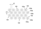
- the micropores 103 are provided in multiple (multiple) positions at predetermined intervals vertically and horizontally on the surface of the disk-shaped filter body 102, and the pitch P1 between adjacent micropores 103, 103 in the vertical direction is equal to the pitch P2 between adjacent micropores 103, 103 in the horizontal direction, but the pitch P1 and the pitch P2 may be different.
- the thickness t1 of the partition between adjacent physical foaming agent introduction holes 103b, 103b in the vertical direction and the thickness t2 of the partition between adjacent physical foaming agent introduction holes 103b, 103b in the horizontal direction are 0.01 to 1.0 mm.
- the reason why the thicknesses t1, t2 of the partitions between adjacent physical foaming agent introduction holes 103b, 103b in the vertical and horizontal directions are set to 0.01 to 1.0 mm is that if the thicknesses t1, t2 of the partitions are less than 0.01 mm, the thicknesses t1, t2 of the partitions will be too thin, reducing the strength of the physical foaming agent introduction filter 101, and if they exceed 1.0 mm, the thicknesses t1, t2 of the partitions will be too thick, reducing the number of physical foaming agent introduction holes 103b.
- the plurality (large number) of micropores 103 are arranged vertically and horizontally, but the present invention is not limited to this.
- they may be arranged in a staggered manner, and further, the physical foaming agent introduction holes 103b, 103b adjacent to each other in the vertical direction may be arranged so as to overlap each other partially in the vertical direction.
- the number of micropores 103 per unit area can be increased.
- it is preferable that the thickness t3 of the partition wall between the diagonally adjacent physical foaming agent introduction holes 103b, 103b is thinner than the thickness t2 of the partition wall between the horizontally adjacent physical foaming agent introduction holes 103b, 103b.
- the thickness t3 of the partition wall between the diagonally adjacent physical foaming agent introduction holes 103b, 103b is 0.01 to 1.0 mm.
- the micropores 103 are configured to have a resin contact side hole 103a that opens on one surface side of the filter body 102 and contacts the molten resin, and a physical foaming agent introduction hole 103b that opens on the other surface side of the filter body 102 and communicates with the resin contact side hole 103a, through which a physical foaming agent is introduced.
- the resin contact side hole 103a and the physical foaming agent introduction hole 103b of the micropores 103 have different diameters, but the micropores 103 may be formed in a straight shape with the same diameter all along their axial direction.
- the filter-equipped body 400 is provided, and the filter holding member 410 of this filter-equipped body 400, which holds the filter 101, is provided on its outer periphery with a sliding member (ball retainer) 415 that allows the inner peripheral surface of the introduction container 300 to slide in the axial direction of the introduction container 300. Therefore, when optimizing the supply amount of resin while visually checking the plasticization state of the molten resin in the starvation zone 23, the operator grasps the flange portion 412 of the filter holding member 410 and pulls it out in the axial direction of the introduction container 300.
- the filter holding member 410 i.e., the filter-equipped body 400, slides in the axial direction on the inner peripheral surface of the introduction container 300 by the sliding member 415, so that the filter-equipped body 400 can be removed from the introduction container 300.
- This allows the starvation zone 23 to be visually checked through the introduction port 202. Therefore, the supply amount of molten resin can be optimized while visually checking the plasticization state of the molten resin in the starvation zone 23.
- the filter holding member 410 holding the filter 101 for introducing a physical foaming agent i.e., the filter-equipped body 400
- the filter holding member 410 holding the filter 101 for introducing a physical foaming agent can be grasped and inserted into the introduction container 300 to provide the filter 101 at the introduction port 202, thereby preventing the molten resin from flowing back into the introduction container 300 and becoming stuck there due to venting up, for example.
- the gap between the outer surface of the tip of the filter holding member 410 and the inner surface of the tip of the introduction container 300 is narrow at 50 ⁇ m or less, it is possible to prevent starved molten resin from entering the introduction container 300 through the gap.
- the diameter of the resin contact side hole 103a of the physical foaming agent introduction filter 101 is equal to or smaller than the diameter of the physical foaming agent introduction hole 103b and is 10 to 80 ⁇ m, by providing such a physical foaming agent introduction filter 101 at the introduction port 202 for introducing a physical foaming agent into the starvation zone 23 of the plasticizing cylinder 210, it is possible to suppress the intrusion of the molten resin in the starvation zone 23 into the resin contact side hole 103a. Therefore, the molten resin does not solidify and remain in the introduction port 202 where the physical foaming agent introduction filter 101 is provided.
- the physical foaming agent can be reliably introduced from the inlet 202 through the resin contact side holes 103a into the molten resin in a starved state (starvation zone 23). Therefore, vent-up can be suppressed and the physical foaming agent can be stably supplied to the molten resin in a starved state (starvation zone 23).
- Plasticization zone 23 Starvation zone 101 Filter 202 Inlet 210 Plasticization cylinder 300 Inlet container 400 Filter-equipped body 410 Filter holding member 415 Sliding member (ball retainer) 1000 Manufacturing Equipment
Landscapes
- Engineering & Computer Science (AREA)
- Manufacturing & Machinery (AREA)
- Mechanical Engineering (AREA)
- Molding Of Porous Articles (AREA)
- Injection Moulding Of Plastics Or The Like (AREA)
Priority Applications (4)
| Application Number | Priority Date | Filing Date | Title |
|---|---|---|---|
| CN202380100353.6A CN121487822A (zh) | 2023-07-28 | 2023-07-28 | 过滤器安装体、发泡成型体的制造装置及制造方法 |
| KR1020267000233A KR20260020177A (ko) | 2023-07-28 | 2023-07-28 | 필터 장비체, 발포 성형체의 제조 장치 및 제조 방법 |
| JP2025537302A JPWO2025027676A1 (cg-RX-API-DMAC7.html) | 2023-07-28 | 2023-07-28 | |
| PCT/JP2023/027727 WO2025027676A1 (ja) | 2023-07-28 | 2023-07-28 | フィルタ装備体、発泡成形体の製造装置および製造方法 |
Applications Claiming Priority (1)
| Application Number | Priority Date | Filing Date | Title |
|---|---|---|---|
| PCT/JP2023/027727 WO2025027676A1 (ja) | 2023-07-28 | 2023-07-28 | フィルタ装備体、発泡成形体の製造装置および製造方法 |
Publications (1)
| Publication Number | Publication Date |
|---|---|
| WO2025027676A1 true WO2025027676A1 (ja) | 2025-02-06 |
Family
ID=94394353
Family Applications (1)
| Application Number | Title | Priority Date | Filing Date |
|---|---|---|---|
| PCT/JP2023/027727 Ceased WO2025027676A1 (ja) | 2023-07-28 | 2023-07-28 | フィルタ装備体、発泡成形体の製造装置および製造方法 |
Country Status (4)
| Country | Link |
|---|---|
| JP (1) | JPWO2025027676A1 (cg-RX-API-DMAC7.html) |
| KR (1) | KR20260020177A (cg-RX-API-DMAC7.html) |
| CN (1) | CN121487822A (cg-RX-API-DMAC7.html) |
| WO (1) | WO2025027676A1 (cg-RX-API-DMAC7.html) |
Citations (7)
| Publication number | Priority date | Publication date | Assignee | Title |
|---|---|---|---|---|
| WO2013129659A1 (ja) * | 2012-03-02 | 2013-09-06 | 日立マクセル株式会社 | 成形体の製造方法、メッキ膜を有する成形体の製造方法、樹脂ペレットの製造方法、メッキ膜を有する発泡成形体、発泡射出成形方法、ノズルユニット及び射出成形装置 |
| JP2014507313A (ja) * | 2011-01-27 | 2014-03-27 | ニュー バランス アスレティック シュー,インコーポレーテッド | 履物に用いられる材料を形成するための射出成形システム及び方法並びにそのシステム及び方法によって製造される材料 |
| WO2015174255A1 (ja) * | 2014-05-11 | 2015-11-19 | 鈴木康公 | 成形品の製造方法、成形品の製造装置 |
| WO2017159166A1 (ja) * | 2016-03-15 | 2017-09-21 | 日立マクセル株式会社 | 発泡成形体の製造方法及び製造装置 |
| WO2020184486A1 (ja) * | 2019-03-08 | 2020-09-17 | 三恵技研工業株式会社 | 発泡成形体の製造装置、発泡成形体の製造方法および発泡成形体製造装置用スクリュ |
| JP2020157774A (ja) * | 2015-07-08 | 2020-10-01 | マクセル株式会社 | 発泡成形体の製造装置 |
| WO2023026611A1 (ja) * | 2021-08-24 | 2023-03-02 | マクセル株式会社 | 物理発泡剤導入用フィルタ、発泡成形体の製造装置および製造方法 |
Family Cites Families (1)
| Publication number | Priority date | Publication date | Assignee | Title |
|---|---|---|---|---|
| JP6777553B2 (ja) | 2017-01-11 | 2020-10-28 | マクセル株式会社 | 発泡成形体の製造方法及び製造装置 |
-
2023
- 2023-07-28 JP JP2025537302A patent/JPWO2025027676A1/ja active Pending
- 2023-07-28 CN CN202380100353.6A patent/CN121487822A/zh active Pending
- 2023-07-28 WO PCT/JP2023/027727 patent/WO2025027676A1/ja not_active Ceased
- 2023-07-28 KR KR1020267000233A patent/KR20260020177A/ko active Pending
Patent Citations (7)
| Publication number | Priority date | Publication date | Assignee | Title |
|---|---|---|---|---|
| JP2014507313A (ja) * | 2011-01-27 | 2014-03-27 | ニュー バランス アスレティック シュー,インコーポレーテッド | 履物に用いられる材料を形成するための射出成形システム及び方法並びにそのシステム及び方法によって製造される材料 |
| WO2013129659A1 (ja) * | 2012-03-02 | 2013-09-06 | 日立マクセル株式会社 | 成形体の製造方法、メッキ膜を有する成形体の製造方法、樹脂ペレットの製造方法、メッキ膜を有する発泡成形体、発泡射出成形方法、ノズルユニット及び射出成形装置 |
| WO2015174255A1 (ja) * | 2014-05-11 | 2015-11-19 | 鈴木康公 | 成形品の製造方法、成形品の製造装置 |
| JP2020157774A (ja) * | 2015-07-08 | 2020-10-01 | マクセル株式会社 | 発泡成形体の製造装置 |
| WO2017159166A1 (ja) * | 2016-03-15 | 2017-09-21 | 日立マクセル株式会社 | 発泡成形体の製造方法及び製造装置 |
| WO2020184486A1 (ja) * | 2019-03-08 | 2020-09-17 | 三恵技研工業株式会社 | 発泡成形体の製造装置、発泡成形体の製造方法および発泡成形体製造装置用スクリュ |
| WO2023026611A1 (ja) * | 2021-08-24 | 2023-03-02 | マクセル株式会社 | 物理発泡剤導入用フィルタ、発泡成形体の製造装置および製造方法 |
Also Published As
| Publication number | Publication date |
|---|---|
| CN121487822A (zh) | 2026-02-06 |
| JPWO2025027676A1 (cg-RX-API-DMAC7.html) | 2025-02-06 |
| KR20260020177A (ko) | 2026-02-10 |
Similar Documents
| Publication | Publication Date | Title |
|---|---|---|
| CN111546561B (zh) | 发泡成形体的制造方法及制造装置 | |
| KR102058641B1 (ko) | 발포 성형체의 제조 방법 및 제조 장치 | |
| JP6777553B2 (ja) | 発泡成形体の製造方法及び製造装置 | |
| JP6560470B1 (ja) | 発泡成形体の製造装置、発泡成形体の製造方法および発泡成形体製造装置用スクリュ | |
| JP7101471B2 (ja) | 発泡成形体の製造方法及び製造装置 | |
| JP7519967B2 (ja) | 物理発泡剤導入用フィルタ、発泡成形体の製造装置および製造方法 | |
| CN109906138B (zh) | 发泡成形体的制造方法和制造装置 | |
| JP7390585B2 (ja) | 発泡成形体の製造装置 | |
| JP7270501B2 (ja) | 発泡成形体の押出製造装置、押出製造方法および発泡成形体押出製造装置用スクリュ | |
| KR20260020177A (ko) | 필터 장비체, 발포 성형체의 제조 장치 및 제조 방법 | |
| JP6997847B2 (ja) | 発泡成形体の製造方法及び製造装置 | |
| JP2020142502A (ja) | 発泡成形体の製造装置、発泡成形体の製造方法および発泡成形体製造装置用スクリュ |
Legal Events
| Date | Code | Title | Description |
|---|---|---|---|
| 121 | Ep: the epo has been informed by wipo that ep was designated in this application |
Ref document number: 23947476 Country of ref document: EP Kind code of ref document: A1 |
|
| ENP | Entry into the national phase |
Ref document number: 2025537302 Country of ref document: JP Kind code of ref document: A |
|
| ENP | Entry into the national phase |
Ref document number: 1020267000233 Country of ref document: KR Free format text: ST27 STATUS EVENT CODE: A-0-1-A10-A15-NAP-PA0105 (AS PROVIDED BY THE NATIONAL OFFICE) |
|
| WWE | Wipo information: entry into national phase |
Ref document number: 1020267000233 Country of ref document: KR |
|
| WWP | Wipo information: published in national office |
Ref document number: 1020267000233 Country of ref document: KR |
|
| NENP | Non-entry into the national phase |
Ref country code: DE |
|
| 122 | Ep: pct application non-entry in european phase |
Ref document number: 23947476 Country of ref document: EP Kind code of ref document: A1 |