WO2025022845A1 - 空気入りタイヤ - Google Patents
空気入りタイヤ Download PDFInfo
- Publication number
- WO2025022845A1 WO2025022845A1 PCT/JP2024/021228 JP2024021228W WO2025022845A1 WO 2025022845 A1 WO2025022845 A1 WO 2025022845A1 JP 2024021228 W JP2024021228 W JP 2024021228W WO 2025022845 A1 WO2025022845 A1 WO 2025022845A1
- Authority
- WO
- WIPO (PCT)
- Prior art keywords
- tire
- groove
- width direction
- widthwise
- grooves
- Prior art date
- Legal status (The legal status is an assumption and is not a legal conclusion. Google has not performed a legal analysis and makes no representation as to the accuracy of the status listed.)
- Ceased
Links
Images

Classifications
-
- B—PERFORMING OPERATIONS; TRANSPORTING
- B60—VEHICLES IN GENERAL
- B60C—VEHICLE TYRES; TYRE INFLATION; TYRE CHANGING; CONNECTING VALVES TO INFLATABLE ELASTIC BODIES IN GENERAL; DEVICES OR ARRANGEMENTS RELATED TO TYRES
- B60C11/00—Tyre tread bands; Tread patterns; Anti-skid inserts
- B60C11/03—Tread patterns
- B60C11/0304—Asymmetric patterns
-
- B—PERFORMING OPERATIONS; TRANSPORTING
- B60—VEHICLES IN GENERAL
- B60C—VEHICLE TYRES; TYRE INFLATION; TYRE CHANGING; CONNECTING VALVES TO INFLATABLE ELASTIC BODIES IN GENERAL; DEVICES OR ARRANGEMENTS RELATED TO TYRES
- B60C11/00—Tyre tread bands; Tread patterns; Anti-skid inserts
- B60C11/03—Tread patterns
- B60C11/0306—Patterns comprising block rows or discontinuous ribs
-
- B—PERFORMING OPERATIONS; TRANSPORTING
- B60—VEHICLES IN GENERAL
- B60C—VEHICLE TYRES; TYRE INFLATION; TYRE CHANGING; CONNECTING VALVES TO INFLATABLE ELASTIC BODIES IN GENERAL; DEVICES OR ARRANGEMENTS RELATED TO TYRES
- B60C11/00—Tyre tread bands; Tread patterns; Anti-skid inserts
- B60C11/03—Tread patterns
- B60C11/032—Patterns comprising isolated recesses
-
- B—PERFORMING OPERATIONS; TRANSPORTING
- B60—VEHICLES IN GENERAL
- B60C—VEHICLE TYRES; TYRE INFLATION; TYRE CHANGING; CONNECTING VALVES TO INFLATABLE ELASTIC BODIES IN GENERAL; DEVICES OR ARRANGEMENTS RELATED TO TYRES
- B60C11/00—Tyre tread bands; Tread patterns; Anti-skid inserts
- B60C11/03—Tread patterns
- B60C11/04—Tread patterns in which the raised area of the pattern consists only of continuous circumferential ribs, e.g. zig-zag
-
- B—PERFORMING OPERATIONS; TRANSPORTING
- B60—VEHICLES IN GENERAL
- B60C—VEHICLE TYRES; TYRE INFLATION; TYRE CHANGING; CONNECTING VALVES TO INFLATABLE ELASTIC BODIES IN GENERAL; DEVICES OR ARRANGEMENTS RELATED TO TYRES
- B60C11/00—Tyre tread bands; Tread patterns; Anti-skid inserts
- B60C11/03—Tread patterns
- B60C11/12—Tread patterns characterised by the use of narrow slits or incisions, e.g. sipes
- B60C11/1236—Tread patterns characterised by the use of narrow slits or incisions, e.g. sipes with special arrangements in the tread pattern
-
- B—PERFORMING OPERATIONS; TRANSPORTING
- B60—VEHICLES IN GENERAL
- B60C—VEHICLE TYRES; TYRE INFLATION; TYRE CHANGING; CONNECTING VALVES TO INFLATABLE ELASTIC BODIES IN GENERAL; DEVICES OR ARRANGEMENTS RELATED TO TYRES
- B60C11/00—Tyre tread bands; Tread patterns; Anti-skid inserts
- B60C11/03—Tread patterns
- B60C11/13—Tread patterns characterised by the groove cross-section, e.g. for buttressing or preventing stone-trapping
- B60C11/1376—Three dimensional block surfaces departing from the enveloping tread contour
- B60C11/1392—Three dimensional block surfaces departing from the enveloping tread contour with chamfered block edges
-
- B—PERFORMING OPERATIONS; TRANSPORTING
- B60—VEHICLES IN GENERAL
- B60C—VEHICLE TYRES; TYRE INFLATION; TYRE CHANGING; CONNECTING VALVES TO INFLATABLE ELASTIC BODIES IN GENERAL; DEVICES OR ARRANGEMENTS RELATED TO TYRES
- B60C11/00—Tyre tread bands; Tread patterns; Anti-skid inserts
- B60C11/03—Tread patterns
- B60C2011/0337—Tread patterns characterised by particular design features of the pattern
- B60C2011/0339—Grooves
- B60C2011/0341—Circumferential grooves
- B60C2011/0353—Circumferential grooves characterised by width
-
- B—PERFORMING OPERATIONS; TRANSPORTING
- B60—VEHICLES IN GENERAL
- B60C—VEHICLE TYRES; TYRE INFLATION; TYRE CHANGING; CONNECTING VALVES TO INFLATABLE ELASTIC BODIES IN GENERAL; DEVICES OR ARRANGEMENTS RELATED TO TYRES
- B60C11/00—Tyre tread bands; Tread patterns; Anti-skid inserts
- B60C11/03—Tread patterns
- B60C2011/0337—Tread patterns characterised by particular design features of the pattern
- B60C2011/0339—Grooves
- B60C2011/0358—Lateral grooves, i.e. having an angle of 45 to 90 degees to the equatorial plane
- B60C2011/0367—Lateral grooves, i.e. having an angle of 45 to 90 degees to the equatorial plane characterised by depth
- B60C2011/0369—Lateral grooves, i.e. having an angle of 45 to 90 degees to the equatorial plane characterised by depth with varying depth of the groove
-
- B—PERFORMING OPERATIONS; TRANSPORTING
- B60—VEHICLES IN GENERAL
- B60C—VEHICLE TYRES; TYRE INFLATION; TYRE CHANGING; CONNECTING VALVES TO INFLATABLE ELASTIC BODIES IN GENERAL; DEVICES OR ARRANGEMENTS RELATED TO TYRES
- B60C11/00—Tyre tread bands; Tread patterns; Anti-skid inserts
- B60C11/03—Tread patterns
- B60C2011/0337—Tread patterns characterised by particular design features of the pattern
- B60C2011/0386—Continuous ribs
- B60C2011/0388—Continuous ribs provided at the equatorial plane
Definitions
- the present invention relates to pneumatic tires.
- the objective of the present invention is to provide a pneumatic tire with improved grip performance.
- the gist and configuration of the present invention are as follows.
- a pneumatic tire having one or more circumferential main grooves extending in the tire circumferential direction on a tread surface, A plurality of land portions are defined between the circumferential main groove and a tread edge or between the circumferential main grooves,
- the tire has a plurality of first width direction grooves extending in the tire width direction and having at least one end terminated within an outermost land portion when mounted on a vehicle, the outermost land portion when mounted on a vehicle being the outermost land portion in the tire width direction when mounted on a vehicle, and a plurality of second width direction grooves extending in the tire width direction,
- the first widthwise grooves and the second widthwise grooves are alternately arranged in the tire circumferential direction while being spaced apart from each other in the tire circumferential direction,
- One of the first widthwise grooves and one of the second widthwise grooves adjacent to the one of the first widthwise grooves on one side in the tire circumferential direction are paired, The
- tread surface refers to the surface extending around the entire circumferential direction of the tire of the outer surface of the tread that comes into contact with the road surface when the pneumatic tire is mounted on an applicable rim, inflated to the specified internal pressure, and subjected to the maximum load.
- the term “tread edge” refers to both outermost points of the tread surface in the tire width direction.
- the term “circumferential main groove” refers to a groove that extends in the circumferential direction of the tire and has a groove width (opening width) of 2 mm or more in a standard state in which the pneumatic tire is mounted on an applicable rim, inflated to a specified internal pressure, and no load is applied.
- first widthwise groove refers to a groove extending in the tire width direction, the groove width (opening width) in the reference state being 2 mm or more over 80% or more of its extension length
- second widthwise groove refers to a groove extending in the tire width direction, the groove width (opening width) in the reference state being 2 mm or more over 80% or more of its extension length
- inclination angle of the shallow groove described below refers to the inclination angle of a line segment connecting both ends of the shallow groove when the shallow groove does not extend linearly.
- appcable rim refers to the applicable size, which is an industrial standard valid in the region where the tire is manufactured and used, and is described or will be described in the applicable size in the applicable size chart ...
- standard rim refers to the standard rim for a tire in the industry (Measuring Rim in the ETRTO Standards Manual, Design Rim in the TRA Year Book) (i.e., “rim” above includes not only current sizes but also sizes that may be included in the above industry standards in the future.
- An example of "sizes to be described in the future” is the size listed as “FUTURE DEVELOPMENTS" in the 2013 edition of ETRTO).
- “prescribed internal pressure” refers to the air pressure (maximum air pressure) corresponding to the maximum load capacity of a single wheel in the applicable size and ply rating as listed in the above JATMA etc.
- “prescribed internal pressure” refers to the air pressure (maximum air pressure) corresponding to the maximum load capacity specified for each vehicle on which the tire is to be fitted.
- maximum load refers to the load that corresponds to the maximum load capacity mentioned above.
- a pneumatic tire having one or more circumferential main grooves extending in the tire circumferential direction on a tread surface, A plurality of land portions are defined between the circumferential main groove and a tread edge or between the circumferential main grooves,
- the tire has a plurality of first width direction grooves extending in the tire width direction and having at least one end terminated within an outermost land portion when mounted on a vehicle, the outermost land portion when mounted on a vehicle being the outermost land portion in the tire width direction when mounted on a vehicle, and a plurality of second width direction grooves extending in the tire width direction,
- the first widthwise grooves and the second widthwise grooves are alternately arranged in the tire circumferential direction while being spaced apart from each other in the tire circumferential direction,
- One of the first widthwise grooves and one of the second widthwise grooves adjacent to the one of the first widthwise grooves on one side in the tire circumferential direction are paired,
- the first widthwise groove of the pair has a first portion extending
- the present invention provides a pneumatic tire with improved grip performance.
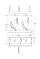
- FIG. 1 is a diagram showing a tread pattern of a pneumatic tire according to a first embodiment of the present invention.
- FIG. 11 is a diagram showing a tread pattern of a pneumatic tire according to a third embodiment of the present invention.
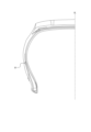
- FIG. 1 is a diagram for explaining an example of an arrangement of communication devices.
- the internal structure of the pneumatic tire according to the first embodiment of the present invention (hereinafter, simply referred to as the "tire") can be the same as that of a conventional tire, and therefore a detailed description thereof will be omitted.
- the tire can include a pair of bead portions, a carcass that spans the pair of bead portions in a toroidal shape, and a belt that is disposed on the radially outer side of the crown portion of the carcass.
- FIG. 1 shows the tread pattern of a pneumatic tire according to a first embodiment of the present invention.
- dimensions refer to dimensions in the standard state unless otherwise specified.
- this tire has one or more (two in the illustrated example) circumferential main grooves 2 (2a, 2b) extending in the tire circumferential direction on the tread surface 1.
- the tire also has a plurality of land portions 3 (3a, 3b (3b1, 3b2)) defined between the circumferential main groove 2 and the tread edge TE or between the circumferential main grooves 2 (2a, 2b).
- the outermost land portion 3a when mounted on the vehicle is defined by the circumferential main groove 2a and the tread edge TE.
- the inner land portion 3b when mounted on the vehicle is defined between the circumferential main grooves 2a, 2b or by the circumferential main groove 2b and the tread edge TE.
- an inner land portion 3b2 of the inner land portion when mounted on the vehicle is defined, and an outer land portion 3b1 of the inner land portion when mounted on the vehicle is defined by the circumferential main groove 2a and the tread edge TE.
- This tire has a plurality of first widthwise grooves 4 that extend in the tire width direction and have at least one end (both ends in the illustrated example) terminate within the outermost land portion 3a when mounted on the vehicle, which is the outermost land portion in the tire width direction when mounted on the vehicle, and a plurality of second widthwise grooves 5 that extend in the tire width direction.
- the first widthwise grooves 4 and the second widthwise grooves 5 are alternately arranged in the tire circumferential direction while being spaced apart from each other in the tire circumferential direction.
- one first widthwise groove 4 and one second widthwise groove 5 adjacent to the one first widthwise groove 4 on one side in the tire circumferential direction form a pair, and a plurality of such pairs are provided at intervals in the tire circumferential direction.
- the pitch interval of the first widthwise grooves 4 in the tire circumferential direction is not particularly limited, but may be, for example, 40 to 140 mm.
- the pitch interval of the second widthwise grooves 5 in the tire circumferential direction is not particularly limited, but may be, for example, 40 to 140 mm.
- the shortest distance between the pair of first widthwise grooves 4 and second widthwise grooves 5 is not particularly limited, but may be, for example, 15 to 60 mm.
- a first widthwise groove 4 of the pair has a first portion 41 that extends from the outer side in the tire width direction toward the inside, toward one side in the tire circumferential direction.
- the first widthwise groove 4 also has a second portion 42 that extends from the inner end of the first portion 41 in the tire width direction toward one side in the tire circumferential direction. This second portion 42 can further ensure drainage.
- the groove width (opening width) of the first widthwise groove 4 is not particularly limited, but can be, for example, 5 to 20 mm, in consideration of the balance between drainage (compliance with regulations when used in racing tires; the same applies below) and the rigidity of the land portion.
- the groove depth (maximum depth) of the first widthwise groove 4 is not particularly limited, but can be, for example, 5 to 8 mm, in consideration of the balance between drainage and the rigidity of the land portion.
- the inclination angle of the first portion 41 with respect to the tire width direction is not particularly limited, but can be, for example, 10 to 20°.
- the rigidity against the input in the width direction (rigidity against shear deformation due to the input from the outside to the inside in the width direction during vehicle cornering) can be increased, and by making it 10° or more, the difference in the direction of inclination with the second widthwise groove 5 can be made clearer, as described later, and both can improve grip performance.
- the inclination angle of the second portion 42 with respect to the tire circumferential direction is not particularly limited, but can be, for example, 10 to 15°.
- one of the pair of second widthwise grooves 5 extends from the outer side in the tire width direction toward the inner side toward the other side in the tire circumferential direction.
- the first widthwise groove 4 and the second widthwise groove 5 are inclined in opposite directions in the tire circumferential direction with respect to the tire width direction.
- the groove width (opening width) of the second widthwise groove 5 is not particularly limited, but can be, for example, 5 to 20 mm, in consideration of the balance between drainage (compliance with regulations when used in racing tires; the same applies below) and the rigidity of the land portion.
- the groove depth (maximum depth) of the second widthwise groove 5 is not particularly limited, but can be, for example, 5 to 8 mm, in consideration of the balance between drainage and the rigidity of the land portion.
- the inclination angle of the second widthwise groove 5 with respect to the tire width direction is not particularly limited, but can be, for example, 5 to 15°.
- the rigidity against the input in the width direction (rigidity against shear deformation due to input from the outside to the inside in the width direction while the vehicle is cornering) can be increased, and by making it 5° or more, the difference in the direction of inclination with the first widthwise groove 4 can be made clearer, as described later, and both can improve grip performance.
- the tire width direction inner end of one second width direction groove 5 constituting the pair is located outside in the tire width direction from the tire width direction inner end of one first width direction groove 4 constituting the pair (in this example, the tire width direction inner end of the second portion 42).
- the tire width direction inner end of one second width direction groove 5 constituting the pair is located outside in the tire width direction by a distance of 50 to 80% of the tire width direction width (tire width direction width when projected in the tire circumferential direction) of the first width direction groove 4 from the tire width direction inner end of one first width direction groove 4 constituting the pair (in this example, the tire width direction inner end of the second portion 42).
- the second width direction groove 5 (its tire width direction outer end) is connected to the outer tread edge TE when mounted on the vehicle.
- one first width direction groove 4 constituting the pair and one second width direction groove 5 constituting the pair have an overlapping portion when projected in the tire circumferential direction.
- This overlap width is not particularly limited, but can be, for example, 20 to 50% of the width of the first widthwise groove 4 in the tire width direction (the width in the tire width direction when projected in the tire circumferential direction).
- At least a part of the first portion 41 or at least a part of the second portion 42 has a chamfered portion at the opening to the tread surface 1. This ensures high drainage when new (easier to comply with regulations when used in racing tires), while at the same time ensuring grip performance by suppressing the decrease in rigidity compared to when the opening width is the same as the groove bottom.
- a chamfered portion can be formed only on the first portion 41 (whole circumference or part) (no chamfered portion is formed on the second portion 42).
- a chamfered portion can be formed only on the second portion 42 (whole circumference or part) (no chamfered portion is formed on the first portion 41).
- a chamfered portion can be formed on both the first portion 41 (whole circumference or part) and the second portion 42 (whole circumference or part).
- a chamfered portion is formed on the whole circumference of the first portion 41 and the whole circumference of the second portion 42.
- at least a part of the second widthwise groove 5 (whole circumference or part, in this example, the whole circumference) has a chamfered portion at the opening to the tread surface 1.
- the inclination angle of the tapered surface of the chamfer of the second portion 42 with respect to the tire radial direction is greater than the inclination angle of the tapered surface of the chamfer of the first portion 41 with respect to the tire radial direction. This is because the second portion 42 can further suppress the decrease in rigidity when ensuring drainage performance when new.
- this tire has only two circumferential main grooves 2a, 2b in the inner land portion 3b, which is on the inside when mounted on the vehicle. This ensures a good balance between drainage and rigidity of the land portion.
- third widthwise grooves 6 When mounted on a vehicle, multiple third widthwise grooves 6 extending in the tire width direction are arranged in the outer land portion 3b1 of the inner land portion 3b.
- the third widthwise grooves 6 (their outer ends in the tire width direction) are connected to the tread edge TE. This can improve drainage.
- the third widthwise grooves 6 (their inner ends in the tire width direction) are not connected to the circumferential main groove 2a. This can ensure the rigidity of the land portion.
- the groove width (opening width) of the third widthwise groove 6 is not particularly limited, but can be, for example, 10 to 25 mm in consideration of the balance between drainage (compliance with regulations when used in racing tires; the same applies below) and the rigidity of the land portion.
- the groove depth (maximum depth) of the third widthwise groove 6 is not particularly limited, but can be, for example, 5 to 8 mm in consideration of the balance between drainage and the rigidity of the land portion.
- the inclination angle of the third widthwise groove 6 with respect to the tire width direction is not particularly limited, but can be, for example, 5 to 15°.
- the opening of the third widthwise groove 6 also has a chamfer formed on at least a part (all or a part) of the opening.
- cutouts 7 that communicate with the circumferential main groove 2a are provided on the inner side of the circumferential main groove 2a in the tire width direction. This allows the rigidity of the land portion where the cutouts 7 are provided to be appropriately reduced, improving grip performance. In addition, since the cutouts 7 are provided within the inner land portion 3b when mounted on the vehicle, they are less susceptible to the effects of lateral forces during cornering.
- first widthwise groove 4 and the second widthwise groove 5 provided in the outermost land portion 3a when mounted on a vehicle and the third widthwise groove 6 provided in the inner land portion 3b when mounted on a vehicle do not overlap each other or only their chamfered portions overlap each other when projected in the tire width direction, because this allows for balancing of the rigidity of the land portions in the tire circumferential direction.
- the pneumatic tire of the first embodiment has, first, a plurality of first widthwise grooves 4 extending in the tire width direction and having at least one end (both ends in the illustrated example) terminating within the outermost land portion 3a when mounted on a vehicle, which is the land portion that is outermost in the tire width direction on the outside when mounted on a vehicle, and a plurality of second widthwise grooves 5 extending in the tire width direction. Therefore, it is possible to increase rigidity against input in the width direction (rigidity against shear deformation due to input from the outside to the inside in the width direction during vehicle cornering) and improve grip performance.
- the first widthwise groove 4 of the pair has a first portion 41 extending from the outside to the inside in the tire width direction to one side in the tire circumferential direction
- the second widthwise groove 5 of the pair extends from the outside to the inside in the tire width direction to the other side in the tire circumferential direction.
- the first portion 41 and the second widthwise groove 5 are spaced apart from each other in the circumferential direction of the tire greater the further outward in the tire width direction they are, so that a larger area of the land portion on the outer side in the tire width direction can be secured, thereby improving grip performance.
- the circumferential distance between the first portion 41 and the second widthwise groove 5 becomes smaller the further inward in the tire width direction they are.
- the tire widthwise inner end of one of the paired second widthwise grooves 5 is located outward in the tire width direction than the tire widthwise inner end of one of the paired first widthwise grooves 4.
- the second widthwise groove 5 communicates with the outer tread edge when the tire is mounted on the vehicle. This is because it is possible to further improve drainage.
- one of the pair of first widthwise grooves 4 and one of the pair of second widthwise grooves 5 have an overlapping portion when projected in the tire circumferential direction. This is because it is easier to ensure a sufficient extension length of the widthwise grooves even when taking into account the positional relationship with other grooves (in the example of FIG. 1, the circumferential main groove 2a).
- each first widthwise groove 4 further has a second portion 42 extending from the inner end of the first portion 41 in the tire width direction to one side in the tire circumferential direction, and that at least a part of the first portion 41 or at least a part of the second portion 42 has a chamfered portion at the opening to the tread surface. This is because it is possible to further improve drainage performance when new while minimizing loss of rigidity.
- the inclination angle of the tapered surface of the chamfered portion of the second portion 42 relative to the tire radial direction is greater than the inclination angle of the tapered surface of the chamfered portion of the first portion 41 relative to the tire radial direction. This is because it is possible to further improve the drainage performance when new while minimizing the decrease in rigidity.
- both the direction of inclination of the first portion of the first widthwise groove in the tire circumferential direction relative to the tire width direction and the direction of inclination of the second widthwise groove in the tire circumferential direction relative to the tire width direction may be opposite to those of the first embodiment described above.
- the tire of the second embodiment has a basic configuration similar to that of the first embodiment described above, and has one or more circumferential main grooves extending in the tire circumferential direction on its tread surface, and has a plurality of land portions partitioned between the circumferential main grooves and the tread ends or between the circumferential main grooves, and has a plurality of first widthwise grooves extending in the tire width direction and having at least one end (preferably both ends) terminating within the outermost land portion as mounted on the vehicle, which is the land portion that is the outermost in the tire width direction when mounted on the vehicle, and a plurality of second widthwise grooves extending in the tire width direction, the first widthwise grooves and the second widthwise grooves being arranged alternately in the tire circumferential direction while being spaced apart from each other in the tire circumferential direction, and one first widthwise groove is paired with one second widthwise groove adjacent to one first widthwise groove on one circumferential side of the one first widthwise groove.
- a first widthwise groove of the pair has a first portion extending from the inner side in the tire width direction toward the outer side, toward one side in the tire circumferential direction, and a second widthwise groove of the pair extends from the inner side in the tire width direction toward the outer side, toward the other side in the tire circumferential direction, and the tire widthwise outer end of the second widthwise groove of the pair is located outward in the tire width direction than the tire widthwise outer end of the first widthwise groove of the pair.
- the tire has a plurality of first widthwise grooves extending in the tire width direction and having at least one end (preferably both ends) terminating within the outermost land portion when mounted on the vehicle, which is the land portion that is outermost in the tire width direction when mounted on the vehicle, and a plurality of second widthwise grooves extending in the tire width direction. Therefore, it is possible to increase rigidity against input in the width direction (rigidity against shear deformation due to input from the outside to the inside in the width direction during vehicle cornering) and improve grip performance.
- the first widthwise groove of the pair has a first portion extending from the inside to the outside in the tire width direction to one side in the tire circumferential direction, and the second widthwise groove of the pair extends from the inside to the outside in the tire width direction to the other side in the tire circumferential direction.
- the first portion and the second widthwise groove are spaced apart from each other in the circumferential direction of the tire greater the further inward in the tire width direction, thereby ensuring a large area of the land portion on the inner side in the tire width direction, thereby improving grip performance.
- the circumferential distance between the first portion and the second widthwise groove becomes smaller the further outward in the tire width direction they are; however, in the pneumatic tire of the second embodiment, the tire widthwise outer end of one second widthwise groove that constitutes a pair is located further outward in the tire width direction than the tire widthwise outer end of one first widthwise groove that constitutes the pair.
- the grip performance can also be improved by the pneumatic tire of the second embodiment.
- the second widthwise groove communicates with the outer tread edge when the tire is mounted on the vehicle. This is because drainage can be further improved.
- a first widthwise groove that constitutes a pair and a second widthwise groove that constitutes a pair have an overlapping portion when projected in the tire circumferential direction. This is because it is easier to ensure a sufficient extension length of the widthwise groove even when taking into account the positional relationship with other grooves.
- one first widthwise groove further has a second portion extending from the inner end of the first portion in the tire width direction to one side in the tire circumferential direction, and that at least a part of the first portion or at least a part of the second portion has a chamfered portion at the opening to the tread surface. This is because it is possible to further improve drainage performance when new while minimizing loss of rigidity.
- the inclination angle of the tapered surface of the chamfered portion of the second portion with respect to the tire radial direction is greater than the inclination angle of the tapered surface of the chamfered portion of the first portion with respect to the tire radial direction. This is because it is possible to further improve the drainage performance when new while minimizing the decrease in rigidity.
- the inner land portion it is preferable to have only two circumferential main grooves on the inner land portion, which is on the inside when the tire is installed on the vehicle. This ensures a good balance between drainage and rigidity of the land portion.
- first widthwise groove first portion, second portion
- second widthwise groove in the second embodiment can be the same as those of the first embodiment described above, except for the direction of inclination in the tire circumferential direction relative to the tire width direction.
- overlap width in the tire width direction of the first widthwise groove and the second widthwise groove, and the separation distance in the tire width direction between the outer ends can also be the same as those of the first embodiment described above.
- the tire has one or more (two in the illustrated example) circumferential main grooves 2 (2a, 2b) extending in the tire circumferential direction on the tread surface 1.
- the tire has a plurality of land portions 3 (3a, 3b (3b1, 3b2)) defined between the circumferential main groove 2 and the tread end TE or between the circumferential main grooves 2 (2a, 2b).
- land portions 3a, 3b (3b1, 3b2) defined between the circumferential main groove 2 and the tread end TE or between the circumferential main grooves 2 (2a, 2b.
- an inner land portion 3b when mounted on the vehicle is defined between the circumferential main grooves 2a, 2b or by the circumferential main groove 2b and the tread end TE.
- An inner land portion 3b2 of the inner land portion when mounted on a vehicle is defined between the circumferential main grooves 2a, 2b, and an outer land portion 3b1 of the inner land portion when mounted on a vehicle is defined by the circumferential main groove 2a and the tread edge TE.
- This tire has a plurality of first widthwise grooves 4 that extend in the tire width direction in the outermost land portion 3a when mounted on the vehicle, which is the land portion that is outermost in the tire width direction when mounted on the vehicle, and at least one end (both ends in the illustrated example) terminate within the outermost land portion 3a when mounted on the vehicle, and a plurality of second widthwise grooves 5 that extend in the tire width direction and at least one end (one end in the illustrated example) terminate within the outermost land portion 3a when mounted on the vehicle.
- the first widthwise grooves 4 and the second widthwise grooves 5 are alternately arranged in the tire circumferential direction while being spaced apart from each other in the tire circumferential direction.
- one first widthwise groove 4 and one second widthwise groove 5 adjacent to the one first widthwise groove 4 on one side in the tire circumferential direction form a pair, and a plurality of such pairs are provided at intervals in the tire circumferential direction.
- the pitch interval of the first widthwise grooves 4 in the tire circumferential direction is not particularly limited, but may be, for example, 40 to 140 mm.
- the pitch interval of the second widthwise grooves 5 in the tire circumferential direction is not particularly limited, but may be, for example, 40 to 140 mm.
- the shortest distance between the pair of first widthwise grooves 4 and second widthwise grooves 5 is not particularly limited, but may be, for example, 15 to 60 mm.
- a first widthwise groove 4 of the pair has a first portion 41 that extends from the outer side in the tire width direction toward the inside, toward one side in the tire circumferential direction.
- the first widthwise groove 4 also has a second portion 42 that extends from the inner end of the first portion 41 in the tire width direction toward one side in the tire circumferential direction. This second portion 42 can further ensure drainage.
- the groove width (opening width) of the first widthwise groove 4 is not particularly limited, but can be, for example, 5 to 20 mm, in consideration of the balance between drainage (compliance with regulations when used in racing tires; the same applies below) and the rigidity of the land portion.
- the groove depth (maximum depth) of the first widthwise groove 4 is not particularly limited, but can be, for example, 5 to 8 mm, in consideration of the balance between drainage and the rigidity of the land portion.
- the inclination angle of the first portion 41 with respect to the tire width direction is not particularly limited, but can be, for example, 10 to 20°.
- the rigidity against the input in the width direction (rigidity against shear deformation due to the input from the outside to the inside in the width direction during vehicle cornering) can be increased, and by making it 10° or more, the difference in the direction of inclination with the second widthwise groove 5 can be made clearer, as described later, and both can improve grip performance.
- the inclination angle of the second portion 42 with respect to the tire circumferential direction is not particularly limited, but can be, for example, 10 to 15°.
- one of the pair of second widthwise grooves 5 extends from the outer side in the tire width direction toward the inner side toward the other side in the tire circumferential direction.
- the first widthwise groove 4 and the second widthwise groove 5 are inclined in opposite directions in the tire circumferential direction with respect to the tire width direction.
- the groove width (opening width) of the second widthwise groove 5 is not particularly limited, but can be, for example, 5 to 20 mm, in consideration of the balance between drainage (compliance with regulations when used in racing tires; the same applies below) and the rigidity of the land portion.
- the groove depth (maximum depth) of the second widthwise groove 5 is not particularly limited, but can be, for example, 5 to 8 mm, in consideration of the balance between drainage and the rigidity of the land portion.
- the inclination angle of the second widthwise groove 5 with respect to the tire width direction is not particularly limited, but can be, for example, 5 to 15°.
- the rigidity against the input in the width direction (rigidity against shear deformation due to input from the outside to the inside in the width direction while the vehicle is cornering) can be increased, and by making it 5° or more, the difference in the direction of inclination with the first widthwise groove 4 can be made clearer, as described later, and both can improve grip performance.
- the tire width direction inner end of one second width direction groove 5 constituting the pair is located outside in the tire width direction from the tire width direction inner end of one first width direction groove 4 constituting the pair (in this example, the tire width direction inner end of the second portion 42).
- the tire width direction inner end of one second width direction groove 5 constituting the pair is located outside in the tire width direction by a distance of 50 to 80% of the tire width direction width (tire width direction width when projected in the tire circumferential direction) of the first width direction groove 4 from the tire width direction inner end of one first width direction groove 4 constituting the pair (in this example, the tire width direction inner end of the second portion 42).
- the second width direction groove 5 (its tire width direction outer end) is connected to the outer tread edge TE when mounted on the vehicle.
- one first width direction groove 4 constituting the pair and one second width direction groove 5 constituting the pair have an overlapping portion when projected in the tire circumferential direction.
- This overlap width is not particularly limited, but can be, for example, 20 to 50% of the width of the first widthwise groove 4 in the tire width direction (the width in the tire width direction when projected in the tire circumferential direction).
- At least a part of the first portion 41 or at least a part of the second portion 42 has a chamfered portion at the opening to the tread surface 1. This ensures high drainage when new (easier to comply with regulations when used in racing tires), while at the same time ensuring grip performance by suppressing the decrease in rigidity compared to when the opening width is the same as the groove bottom.
- a chamfered portion can be formed only on the first portion 41 (whole circumference or part) (no chamfered portion is formed on the second portion 42).
- a chamfered portion can be formed only on the second portion 42 (whole circumference or part) (no chamfered portion is formed on the first portion 41).
- a chamfered portion can be formed on both the first portion 41 (whole circumference or part) and the second portion 42 (whole circumference or part).
- a chamfered portion is formed on the whole circumference of the first portion 41 and the whole circumference of the second portion 42.
- at least a part of the second widthwise groove 5 (whole circumference or part, in this example, the whole circumference) has a chamfered portion at the opening to the tread surface 1.
- the inclination angle of the tapered surface of the chamfer of the second portion 42 with respect to the tire radial direction is greater than the inclination angle of the tapered surface of the chamfer of the first portion 41 with respect to the tire radial direction. This is because the second portion 42 can further suppress the decrease in rigidity when ensuring drainage performance when new.
- this tire has only two circumferential main grooves 2a, 2b in the inner land portion 3b, which is on the inside when mounted on the vehicle. This ensures a good balance between drainage and rigidity of the land portion.
- the outer land portion 3b1 of the inner land portion 3b has a plurality of third widthwise grooves 6 arranged therein, extending in the tire width direction.
- the third widthwise grooves 6 (at their tire widthwise outer ends) are connected to the tread edge TE. This allows for improved drainage.
- the third widthwise grooves 6 (at their tire widthwise inner ends) are not connected to the circumferential main grooves 2a. This allows for the rigidity of the land portion to be ensured.
- a fourth widthwise groove 9 is further arranged between the third widthwise grooves 6 in the tire circumferential direction. This allows for further improved drainage. Both ends of the fourth widthwise groove 9 terminate within the outer land portion 3b1. This allows for the rigidity of the land portion to be ensured.
- the groove width of the fourth widthwise groove 9 is smaller than the groove width of the third widthwise groove 6.
- the groove width (opening width) of the third widthwise groove 6 is not particularly limited, but can be, for example, 10 to 25 mm in consideration of the balance between drainage (compliance with regulations when used in racing tires; the same applies below) and the rigidity of the land portion.
- the groove depth (maximum depth) of the third widthwise groove 6 is not particularly limited, but can be, for example, 5 to 8 mm in consideration of the balance between drainage and the rigidity of the land portion.
- the inclination angle of the third widthwise groove 6 with respect to the tire width direction is not particularly limited, but can be, for example, 5 to 15°.
- the groove width (opening width) of the fourth widthwise groove 9 is not particularly limited, but can be, for example, 2 to 6 mm in consideration of the balance between drainage (compliance with regulations when used in racing tires; the same applies below) and the rigidity of the land portion.
- the groove depth (maximum depth) of the fourth widthwise groove 9 is not particularly limited, but can be, for example, 5 to 8 mm in consideration of the balance between drainage and the rigidity of the land portion.
- the inclination angle of the fourth widthwise groove 9 with respect to the tire width direction is not particularly limited, but can be, for example, 5 to 15°. By making it 15° or less, the rigidity against the input in the width direction (rigidity against shear deformation due to input from the outside to the inside in the width direction during vehicle cornering) can be increased, and by making it 5° or more, the rigidity can be prevented from being locally reduced in the tire circumferential direction. It is preferable that the openings of the third widthwise groove 6 and the fourth widthwise groove 9 also have chamfered portions formed at least on a part thereof (all around or a part of the circumference).
- cutouts 7 that communicate with the circumferential main groove 2a are provided on the inner side of the circumferential main groove 2a in the tire width direction. This allows the rigidity of the land portion where the cutouts 7 are provided to be appropriately reduced, improving grip performance. In addition, since the cutouts 7 are provided within the inner land portion 3b when mounted on the vehicle, they are less susceptible to the effects of lateral forces during cornering.
- the first width direction groove 4 and the second width direction groove 5 provided in the outermost land portion 3a when mounted on the vehicle and the third width direction groove 6 provided in the inner land portion 3b when mounted on the vehicle do not overlap each other or that only the chamfered portions overlap. This is because it is possible to balance the rigidity of the land portions in the tire circumferential direction.
- the first width direction groove 4 and the second width direction groove 5 provided in the outermost land portion 3a when mounted on the vehicle and the fourth width direction groove 9 provided in the inner land portion 3b when mounted on the vehicle do not overlap each other or that only the chamfered portions overlap when projected in the tire width direction.
- This tire further includes a shallow groove 8 in the outermost land portion 3a when mounted on a vehicle, one end of which is connected to the other end of the first widthwise groove 4.
- the other end of the shallow groove 8 is connected to the circumferential main groove 2b.
- the groove depth (maximum depth) of the shallow groove 8 is shallower than the groove depth (maximum depth) of the first widthwise groove 4.
- the groove depth (maximum depth) of the shallow groove 8 is preferably 1.0 mm or more and 2.5 mm or less. By making it 1.0 mm or more, drainage can be further improved, while by making it 2.5 mm or less, a decrease in rigidity of the outermost land portion 3a when mounted on the vehicle can be suppressed.
- the groove width (opening width) of the shallow groove 8 is preferably 3.0 to 10.0 mm. By making it 3.0 mm or more, drainage can be further improved, while by making it 10.0 mm or less, a decrease in rigidity of the outermost land portion 3a when mounted on the vehicle can be suppressed.
- the shallow grooves 8 extend from the outer side in the tire width direction to the inner side on one side in the tire circumferential direction. It is preferable that the shallow grooves 8 extend at an inclination angle of 40 to 60 degrees with respect to the tire circumferential direction. By making the angle 40 degrees or more, it is possible to suppress a decrease in the rigidity of localized land portions due to the formation of acute angles, while by making the angle 60 degrees or less, it is possible to further improve drainage.
- the shallow groove 8 is connected to the end of the first widthwise groove 4 (in the illustrated example, the second portion 42) on one circumferential side of the tire (the kick-out side in this example). This is because it encourages water that has entered the first widthwise groove 4 to be drained via the shallow groove 8 into the circumferential main groove 2a, thereby further improving drainage.
- the first widthwise groove 4, the second widthwise groove 5, and the shallow groove 8 as configured above are provided only in the outermost land portion 3a when mounted on a vehicle.
- the effects of the pneumatic tire of the third embodiment will be described below.
- the pneumatic tire of the third embodiment first has a plurality of first widthwise grooves 4 extending in the tire width direction and having at least one end (both ends in the illustrated example) terminating within the outermost land portion 3a when mounted on the vehicle, and a plurality of second widthwise grooves 5 extending in the tire width direction and having at least one end (one end in the illustrated example) terminating within the outermost land portion 3a when mounted on the vehicle, in the outermost land portion 3a when mounted on the vehicle, which is the land portion that is outermost in the tire width direction on the outside when mounted on the vehicle.
- the first widthwise groove 4 of the pair has a first portion 41 extending from the outside to the inside in the tire width direction to one side in the tire circumferential direction
- the second widthwise groove 5 of the pair extends from the outside to the inside in the tire width direction to the other side in the tire circumferential direction.
- the first portion 41 and the second widthwise groove 5 are spaced apart from each other in the circumferential direction of the tire greater the further outward in the tire width direction they are, so that a larger area of the land portion on the outer side in the tire width direction can be secured, thereby improving grip performance.
- the circumferential distance between the first portion 41 and the second widthwise groove 5 becomes smaller the further inward in the tire width direction they are.
- the inner end in the tire width direction of one of the paired second widthwise grooves 5 is located outward in the tire width direction than the inner end in the tire width direction of one of the paired first widthwise grooves 4.
- the first widthwise groove 4 is closed within the contact patch, and the air in the closed space is compressed by the load, generating a pumping sound when released, which can result in pattern noise.
- the tire of the third embodiment further includes a shallow groove 8, one end of which communicates with the other end of the first widthwise groove 4, and the other end of the shallow groove 8 communicates with the circumferential main groove 2b.
- the drainage performance can be further improved by the drainage by the shallow grooves 8 themselves and by the effective drainage by the shallow grooves 8 connecting the circumferential main grooves 2b and the first width direction grooves 4.
- the groove depth of the shallow grooves 8 is shallower than the groove depth of the first width direction grooves 4, the decrease in rigidity of the land portion can also be suppressed.
- the shallow grooves 8 may disappear.
- the groove depth of the first widthwise grooves 4 also becomes shallow, so that the pumping noise that may be generated is also reduced.
- the second widthwise groove 5 communicates with the outer tread edge when the tire is mounted on the vehicle. This is because it is possible to further improve drainage.
- one of the pair of first widthwise grooves 4 and one of the pair of second widthwise grooves 5 have an overlapping portion when projected in the tire circumferential direction. This is because it is easier to ensure a sufficient extension length of the widthwise grooves even when taking into consideration the positional relationship with other grooves (in the example of FIG. 2, the circumferential main groove 2a).
- each first widthwise groove 4 further has a second portion 42 extending from the inner end of the first portion 41 in the tire width direction to one side in the tire circumferential direction, and that at least a part of the first portion 41 or at least a part of the second portion 42 has a chamfered portion at the opening to the tread surface. This is because it is possible to further improve drainage performance when new while minimizing loss of rigidity.
- the inclination angle of the tapered surface of the chamfered portion of the second portion 42 relative to the tire radial direction is greater than the inclination angle of the tapered surface of the chamfered portion of the first portion 41 relative to the tire radial direction. This is because it is possible to further improve the drainage performance when new while minimizing the decrease in rigidity.
- both the direction of inclination of the first portion of the first widthwise groove in the tire circumferential direction relative to the tire width direction and the direction of inclination of the second widthwise groove in the tire circumferential direction relative to the tire width direction may be opposite to those in the third embodiment described above.
- the tire of the fourth embodiment has a basic configuration similar to that of the third embodiment described above, and has, on its tread surface, one or more circumferential main grooves extending in the tire circumferential direction, and a plurality of land portions partitioned between the circumferential main groove and the tread edge or between the circumferential main grooves, and has, in an outermost land portion as mounted on a vehicle, which is the land portion that is the outermost in the tire width direction on the outside when mounted on a vehicle, a plurality of first widthwise grooves that extend in the tire width direction and have at least one end (e.g., both ends) terminate within the outermost land portion as mounted on a vehicle, and a plurality of second widthwise grooves that extend in the tire width direction and have at least one end (e.g., one end) terminate within the outermost land portion as mounted on a vehicle, the first widthwise grooves and the second widthwise grooves are arranged alternately in the tire circumferential direction while being spaced apart from each other in the tire circumfer
- the shallow groove 8 further includes a shallow groove 8 having one end communicating with the other end of the first widthwise groove 4, the shallow groove 8 having a groove depth shallower than the groove depth of the first widthwise groove 4, and the other end of the shallow groove 8 communicating with the circumferential main groove 2a.
- the shallow groove 8 also extends from the outer side toward the inner side in the tire width direction to the other side in the tire circumferential direction.
- a first widthwise groove of the pair has a first portion extending from the inner side in the tire width direction toward the outer side, toward one side in the tire circumferential direction, and a second widthwise groove of the pair extends from the inner side in the tire width direction toward the outer side, toward the other side in the tire circumferential direction, and the tire widthwise outer end of the second widthwise groove of the pair is located outward in the tire width direction than the tire widthwise outer end of the first widthwise groove of the pair.
- the tire has a plurality of first widthwise grooves that extend in the tire width direction and have at least one end (e.g., both ends) terminating within the outermost land portion when mounted on the vehicle, and a plurality of second widthwise grooves that extend in the tire width direction and have at least one end (e.g., one end) terminating within the outermost land portion when mounted on the vehicle, in the outermost land portion when mounted on the vehicle, which is the land portion that is outermost in the tire width direction on the outside when mounted on the vehicle. Therefore, it is possible to increase rigidity against widthwise input (rigidity against shear deformation due to input from the outside to the inside in the width direction during vehicle cornering) and improve grip performance.
- first widthwise grooves that extend in the tire width direction and have at least one end (e.g., both ends) terminating within the outermost land portion when mounted on the vehicle
- second widthwise grooves that extend in the tire width direction and have at least one end (e.g., one end) terminating within the outermost
- the first widthwise groove of the pair has a first portion extending from the inside to the outside in the tire width direction to one side in the tire circumferential direction, and the second widthwise groove of the pair extends from the inside to the outside in the tire width direction to the other side in the tire circumferential direction.
- the first portion and the second widthwise groove are spaced apart from each other in the circumferential direction of the tire greater the further inward in the tire width direction, thereby ensuring a large area of the land portion on the inner side in the tire width direction, thereby improving grip performance.
- the circumferential distance between the first portion and the second widthwise groove becomes smaller the further outward in the tire width direction they are; however, in the pneumatic tire of the fourth embodiment, the tire widthwise outer end of one second widthwise groove that constitutes a pair is located further outward in the tire width direction than the tire widthwise outer end of one first widthwise groove that constitutes the pair.
- the pneumatic tire of the fourth embodiment can also improve the grip performance.
- the tire of the fourth embodiment also includes a shallow groove 8, one end of which communicates with the other end of the first widthwise groove 4, and the other end of the shallow groove 8 communicates with the circumferential main groove 2a.
- the shallow groove 8 functions as an escape route for air, thereby suppressing the generation of the above-mentioned pattern noise.
- the drainage performance can be further improved by the drainage of the shallow grooves 8 themselves and by the effective drainage caused by the shallow grooves 8 connecting the circumferential main grooves 2b and the first width direction grooves 4.
- the groove depth of the shallow grooves 8 is shallower than the groove depth of the first width direction grooves 4, the decrease in rigidity of the land portion can also be suppressed.
- the shallow grooves 8 may disappear.
- the groove depth of the first widthwise grooves 4 also becomes shallow, so that the pumping noise that may be generated is also reduced.
- the groove depth (maximum depth) of the shallow groove 8 is preferably 1.0 mm or more and 2.5 mm or less. By making it 1.0 mm or more, drainage can be further improved, while by making it 2.5 mm or less, a decrease in rigidity of the outermost land portion 3a when mounted on the vehicle can be suppressed.
- the groove width (opening width) of the shallow groove 8 is preferably 3.0 to 10.0 mm. By making it 3.0 mm or more, drainage can be further improved, while by making it 10.0 mm or less, a decrease in rigidity of the outermost land portion 3a when mounted on the vehicle can be suppressed.
- the shallow grooves 8 extend at an inclination angle of 40 to 60 degrees with respect to the tire circumferential direction.
- the angle 40 degrees or more it is possible to suppress a decrease in the rigidity of local land portions due to the formation of acute angles, while by making the angle 60 degrees or less, it is possible to further improve drainage.
- the shallow groove 8 communicates with the end of the first widthwise groove 4 (in the illustrated example, the second portion 42) on one side in the tire circumferential direction (the kick-out side in this example). This is because water that has entered the first widthwise groove 4 is encouraged to drain via the shallow groove 8 to the circumferential main groove 2b, thereby further improving drainage.
- the first widthwise groove 4, the second widthwise groove 5, and the shallow groove 8 are provided only in the outermost land portion 3a when mounted on the vehicle.
- the second widthwise grooves communicate with the outer tread edge when the tire is mounted on the vehicle. This is because drainage can be further improved.
- a first widthwise groove that constitutes a pair and a second widthwise groove that constitutes a pair have an overlapping portion when projected in the tire circumferential direction. This is because it is easier to ensure a sufficient extension length of the widthwise groove even when taking into account the positional relationship with other grooves.
- one first widthwise groove further has a second portion extending from the inner end of the first portion in the tire width direction to one side in the tire circumferential direction, and that at least a part of the first portion or at least a part of the second portion has a chamfered portion at the opening to the tread surface. This is because it is possible to further improve drainage performance when new while minimizing loss of rigidity.
- the inclination angle of the tapered surface of the chamfered portion of the second portion with respect to the tire radial direction is greater than the inclination angle of the tapered surface of the chamfered portion of the first portion with respect to the tire radial direction. This is because it is possible to further improve the drainage performance when new while minimizing the decrease in rigidity.
- the fourth embodiment it is preferable to have only two circumferential main grooves on the inner land portion, which is on the inside when the tire is installed on the vehicle. This ensures a good balance between drainage and rigidity of the land portion.
- first widthwise groove (first portion, second portion) and the second widthwise groove in the fourth embodiment can be the same as those of the third embodiment, except for the direction of inclination in the tire circumferential direction relative to the tire width direction.
- overlap width in the tire width direction of the first widthwise groove and the second widthwise groove, and the separation distance in the tire width direction between the outer ends can also be the same as those of the third embodiment.
- FIG. 3 is a diagram for explaining an example of the arrangement of the communication device.
- this tire may be equipped with an RF tag as a communication device 91.
- the RF tag includes an IC chip and an antenna.
- the RF tag may be arranged, for example, sandwiched between a plurality of members of the same or different types that constitute the tire. In this way, the RF tag can be easily attached during tire production, and the productivity of tires equipped with RF tags can be improved.
- the RF tag may be arranged, for example, sandwiched between a bead filler and another member adjacent to the bead filler.
- the RF tag may be embedded in any of the members that constitute the tire. In this way, the load applied to the RF tag can be reduced compared to when the RF tag is arranged by being sandwiched between a plurality of members that constitute the tire. This can improve the durability of the RF tag.
- the RF tag may be embedded in a rubber member such as a tread rubber or a side rubber. It is preferable that the RF tag is not placed at a position that is a boundary between members having different rigidity in the periphery length direction, which is a direction along the tire outer surface in a cross-sectional view in the tire width direction. In this way, the RF tag is not placed at a position where distortion is likely to concentrate due to a rigidity step.
- the RF tag is not placed at a position that is a boundary between the end of the carcass and a member adjacent to the end of the carcass (e.g., side rubber, etc.) in a cross-sectional view in the tire width direction.
- the number of RF tags is not particularly limited.
- the tire may include only one RF tag, or may include two or more RF tags.
- an RF tag is illustrated as an example of a communication device, but a communication device other than the RF tag may be used.
- the RF tag may be placed, for example, in the tread portion of the tire. In this way, the RF tag is not damaged by a side cut of the tire.
- the RF tag may be placed, for example, in the center of the tread in the tire width direction.
- the center of the tread is a position in the tread portion where bending is unlikely to concentrate. In this way, the load applied to the RF tag can be reduced. This improves the durability of the RF tag.
- the RF tag may be placed, for example, within a range of 1/2 the tread width with the tire equatorial plane as the center in the tire width direction.
- the RF tag may be placed, for example, at the tread end in the tire width direction. If the position of the reader that communicates with the RF tag is predetermined, the RF tag may be placed, for example, at the tread end on one side closer to the reader. In this example, the RF tag may be placed, for example, within a range of 1/4 the tread width with the tread end as the outer end in the tire width direction.
- the RF tag may be arranged, for example, on the tire cavity side of the carcass, which includes one or more carcass plies that span between the bead portions. In this way, the RF tag is less likely to be damaged by impacts applied from outside the tire, or damage such as side cuts and nail penetration.
- the RF tag may be arranged in close contact with the surface of the carcass on the tire cavity side.
- the RF tag may be arranged, for example, between the carcass and another member located on the tire cavity side of the carcass.
- An example of another member located on the tire cavity side of the carcass is an inner liner that forms the tire inner surface.
- the RF tag may be attached to the tire inner surface facing the tire cavity.
- the RF tag By configuring the RF tag to be attached to the tire inner surface, it is easy to attach the RF tag to the tire and to inspect and replace the RF tag. In other words, the ease of attachment and maintenance of the RF tag can be improved.
- the RF tag by attaching the RF tag to the inner surface of the tire, the RF tag can be prevented from becoming the core of tire failure, compared to a configuration in which the RF tag is embedded in the tire.
- the RF tag may be positioned between the overlapped carcass plies.
- the RF tag may be arranged, for example, in the tread portion of the tire, on the tire radial outside of the belt including one or more belt plies.
- the RF tag may be arranged on the tire radial outside of the belt and in close contact with the belt.
- the RF tag may be arranged on the tire radial outside of the reinforcing belt layer and in close contact with the reinforcing belt layer.
- the RF tag may be embedded in the tread rubber on the tire radial outside of the belt.
- the RF tag By arranging the RF tag on the tire radial outside of the belt in the tread portion of the tire, communication with the RF tag from the outside of the tire in the tire radial direction is less likely to be hindered by the belt. Therefore, it is possible to improve communication with the RF tag from the outside of the tire in the tire radial direction.
- the RF tag may be arranged, for example, in the tire tread portion of the tire, on the tire radial inside of the belt. In this way, the tire radial outside of the RF tag is covered by the belt, so that the RF tag is less likely to be damaged by impact from the tread surface or nail penetration.
- the RF tag may be placed in the tread portion of the tire, between the belt and the carcass located radially inward of the belt. Also, if the belt has multiple belt plies, the RF tag may be placed in the tread portion of the tire, between any two belt plies. In this way, the outer side of the RF tag in the tire radial direction is covered by one or more belt plies, making the RF tag less susceptible to damage from impacts from the tread surface or nail penetration.
- the RF tag may be placed, for example, at the sidewall or bead of the tire.
- the RF tag may be placed, for example, at one sidewall or one bead that is close to a reader that can communicate with the RF tag. In this way, the communication between the RF tag and the reader can be improved.
- the RF tag may be placed between the carcass and the side rubber, or between the tread rubber and the side rubber.
- the RF tag may be placed, for example, in the tire radial direction, between the position where the tire is at its maximum width and the position of the tread surface.
- the communication with the RF tag from the outside of the tire in the tire radial direction can be improved compared to a configuration in which the RF tag is placed on the inner side in the tire radial direction from the position where the tire is at its maximum width.
- the RF tag may be placed, for example, on the inner side in the tire radial direction from the position where the tire is at its maximum width. In this way, the RF tag is placed near the bead portion that has high rigidity. Therefore, the load applied to the RF tag can be reduced. This improves the durability of the RF tag.
- the RF tag may be disposed adjacent to the bead core in the tire radial direction or tire width direction. Distortion is unlikely to concentrate near the bead core.
- the load applied to the RF tag can be reduced. This can improve the durability of the RF tag.
- the RF tag is disposed in a position that is radially inward of the maximum tire width position and radially outward of the bead core of the bead portion. In this way, the durability of the RF tag can be improved, and communication between the RF tag and the reader is unlikely to be hindered by the bead core, thereby improving the communication performance of the RF tag.
- the RF tag may be sandwiched between the multiple rubber members that make up the side rubber.
- the RF tag may be disposed by being sandwiched between the bead filler and a member adjacent to the bead filler. In this way, the RF tag can be disposed in a position where distortion is less likely to be concentrated due to the placement of the bead filler. This reduces the load applied to the RF tag. This improves the durability of the RF tag.
- the RF tag may be disposed, for example, sandwiched between the bead filler and the carcass. The portion of the carcass that sandwiches the RF tag together with the bead filler may be located on the outer side of the bead filler in the tire width direction, or may be located on the inner side of the tire width direction.
- the bead filler may have a portion disposed adjacent to the side rubber.
- the RF tag may be disposed sandwiched between the bead filler and the side rubber.
- the bead filler may have a portion disposed adjacent to the rubber chafer. In such a case, the RF tag may be disposed sandwiched between the bead filler and the rubber chafer.
- the RF tag may be arranged, for example, sandwiched between the rubber chafer and the side rubber. In this way, the RF tag can be arranged in a position where distortion is less likely to be concentrated due to the placement of the rubber chafer. This makes it possible to reduce the load on the RF tag. This makes it possible to improve the durability of the RF tag.
- the RF tag may be arranged, for example, sandwiched between the rubber chafer and the carcass. In this way, it makes it possible to reduce the load on the RF tag due to impacts and damage from the rim. This makes it possible to improve the durability of the RF tag.
- the RF tag may be sandwiched between the wire chafer and another adjacent member on the inside or outside of the wire chafer in the tire width direction. This makes it difficult for the position of the RF tag to fluctuate when the tire deforms. This reduces the load applied to the RF tag when the tire deforms. This improves the durability of the RF tag.
- the other member adjacent to the wire chafer on the inside or outside of the tire width direction may be, for example, a rubber member such as a rubber chafer. Also, the other member adjacent to the wire chafer on the inside or outside of the tire width direction may be, for example, a carcass.
- a belt reinforcing layer may be further provided on the radially outer side of the belt.
- the belt reinforcing layer may be formed by winding a cord made of polyethylene terephthalate continuously in a spiral shape in the tire circumferential direction.
- the cord may be adhesive-treated under a tension of 6.9 ⁇ 10 ⁇ 2 N/tex or more, and may have an elastic modulus of 2.5 mN/dtex ⁇ % or more at a load of 29.4 N measured at 160° C.
- the belt reinforcing layer may be arranged so as to cover the entire belt or only both ends of the belt.
- the winding density per unit width of the belt reinforcing layer may differ depending on the position in the width direction. In this way, road noise and flat spots can be reduced without reducing high-speed durability.
Landscapes
- Engineering & Computer Science (AREA)
- Mechanical Engineering (AREA)
- Tires In General (AREA)
Abstract
Description
(1)トレッド踏面に、1本以上のタイヤ周方向に延びる周方向主溝を有する、空気入りタイヤであって、
前記周方向主溝とトレッド端との間又は前記周方向主溝間に区画された、複数の陸部を有し、
車両装着時外側のタイヤ幅方向最外側の陸部である車両装着時最外側陸部に、タイヤ幅方向に延び、前記車両装着時最外側陸部内で少なくとも一端が終端する、複数本の第1の幅方向溝と、タイヤ幅方向に延びる、複数本の第2の幅方向溝と、を有し、
前記第1の幅方向溝と前記第2の幅方向溝とは、タイヤ周方向に互いに離間させながらタイヤ周方向に交互に配列され、
一の前記第1の幅方向溝と、該一の前記第1の幅方向溝に対してタイヤ周方向一方側に隣接する一の前記第2の幅方向溝とが対をなし、
前記対を構成する前記一の第1の幅方向溝は、タイヤ幅方向外側から内側に向かって、タイヤ周方向一方側に延びる第1の部分を有し、
前記対を構成する前記一の第2の幅方向溝は、タイヤ幅方向外側から内側に向かって、タイヤ周方向他方側に延び、
前記対を構成する前記一の第2の幅方向溝のタイヤ幅方向内側端は、前記対を構成する前記一の第1の幅方向溝のタイヤ幅方向内側端よりもタイヤ幅方向外側に位置することを特徴とする、空気入りタイヤ。
また、「トレッド端」とは、上記トレッド踏面のタイヤ幅方向両最外側点をいう。
また、「周方向主溝」とは、タイヤ周方向に延びる溝であって、空気入りタイヤを適用リムに装着し、規定内圧を充填し、無負荷とした、基準状態における溝幅(開口幅)が2mm以上のものをいう。
また、「第1の幅方向溝」とは、タイヤ幅方向に延びる溝であって、前記基準状態における溝幅(開口幅)がその延在長さの80%以上にわたって2mm以上のものをいい、「第2の幅方向溝」とは、タイヤ幅方向に延びる溝であって、前記基準状態における溝幅(開口幅)がその延在長さの80%以上にわたって2mm以上のものをいう。
ここで、後述の浅溝に関する「傾斜角度」は、浅溝が、直線状に延びていない場合は、両端を結んだ線分の傾斜角度をいうものとする。
前記周方向主溝とトレッド端との間又は前記周方向主溝間に区画された、複数の陸部を有し、
車両装着時外側のタイヤ幅方向最外側の陸部である車両装着時最外側陸部に、タイヤ幅方向に延び、前記車両装着時最外側陸部内で少なくとも一端が終端する、複数本の第1の幅方向溝と、タイヤ幅方向に延びる、複数本の第2の幅方向溝と、を有し、
前記第1の幅方向溝と前記第2の幅方向溝とは、タイヤ周方向に互いに離間させながらタイヤ周方向に交互に配列され、
一の前記第1の幅方向溝と、該一の前記第1の幅方向溝に対してタイヤ周方向一方側に隣接する一の前記第2の幅方向溝とが対をなし、
前記対を構成する前記一の第1の幅方向溝は、タイヤ幅方向内側から外側に向かって、タイヤ周方向一方側に延びる第1の部分を有し、
前記対を構成する前記一の第2の幅方向溝は、タイヤ幅方向内側から外側に向かって、タイヤ周方向他方側に延び、
前記対を構成する前記一の第2の幅方向溝のタイヤ幅方向外側端は、前記対を構成する前記一の第1の幅方向溝のタイヤ幅方向外側端よりもタイヤ幅方向外側に位置することを特徴とする、空気入りタイヤ。
本発明の第1の実施形態にかかる空気入りタイヤ(以下、単に「タイヤ」とも称する)の内部構造等については、従来のそれと同様とすることができるため、詳細な説明は省略する。一方で、一例としては、タイヤは、一対のビード部と、一対のビード部間をトロイダル状に跨るカーカスと、カーカスのクラウン部のタイヤ径方向外側に配置されたベルトと、を備えたものとすることができる。
第3の幅方向溝6の開口部においても、その少なくとも一部(全周又は一部)に面取り部が形成されていることが好ましい。
以下、第1の実施形態の空気入りタイヤの作用効果について説明する。
また、第1の実施形態の空気入りタイヤでは、対を構成する一の第1の幅方向溝4は、タイヤ幅方向外側から内側に向かって、タイヤ周方向一方側に延びる第1の部分41を有し、対を構成する一の第2の幅方向溝5は、タイヤ幅方向外側から内側に向かって、タイヤ周方向他方側に延びている。これにより、様々な方向からの入力に対して、常に(タイヤ幅方向に対する、タイヤ周方向への傾斜方向が互いに反対となる)2種類の延在方向の幅方向溝が存在することになるため、特定の方向からの入力に対して陸部が変形しやすくなるといった問題を解消することができ、グリップ性能を向上させることができる。
さらに、このような構成によれば、第1の部分41及び第2の幅方向溝5は、タイヤ幅方向外側ほど互いにタイヤ周方向の離間距離が大きくなるため、タイヤ幅方向外側における陸部の面積を大きく確保して、グリップ性能を向上させることができる。
一方で、傾斜の向きのみだけで考えると、第1の部分41及び第2の幅方向溝5は、タイヤ幅方向内側ほど互いにタイヤ周方向の離間距離が小さくなるが、第1の実施形態の空気入りタイヤでは、対を構成する一の第2の幅方向溝5のタイヤ幅方向内側端が、対を構成する一の第1の幅方向溝4のタイヤ幅方向内側端よりもタイヤ幅方向外側に位置しているため、第1の幅方向溝4と第2の幅方向溝5とがタイヤ周方向に近づく領域をなるべく生じさせないようにして、タイヤ幅方向内側においても、陸部の面積を大きく確保して、グリップ性能を向上させることができる。
以上のように、第1の実施形態の空気入りタイヤによれば、グリップ性能を向上させることができる。
ここで、第2の実施形態としては、第1の幅方向溝の第1の部分のタイヤ幅方向に対するタイヤ周方向への傾斜の向きと第2の幅方向溝のタイヤ幅方向に対するタイヤ周方向への傾斜の向きとの両方が、上記の第1の実施形態と反対側であっても良い。すなわち、第2の実施形態のタイヤは、基本構成は上記の第1の実施形態と同様であり、トレッド踏面に、1本以上のタイヤ周方向に延びる周方向主溝を有し、周方向主溝とトレッド端との間又は周方向主溝間に区画された、複数の陸部を有し、車両装着時外側のタイヤ幅方向最外側の陸部である車両装着時最外側陸部に、タイヤ幅方向に延び、車両装着時最外側陸部内で少なくとも一端が(好ましくは両端が)終端する、複数本の第1の幅方向溝と、タイヤ幅方向に延びる、複数本の第2の幅方向溝と、を有し、第1の幅方向溝と第2の幅方向溝とは、タイヤ周方向に互いに離間させながらタイヤ周方向に交互に配列され、一の第1の幅方向溝と、該一の第1の幅方向溝に対してタイヤ周方向一方側に隣接する一の第2の幅方向溝とが対をなす。
一方で、上記の第1の実施形態とは異なり、第2の実施形態のタイヤでは、対を構成する一の第1の幅方向溝は、タイヤ幅方向内側から外側に向かって、タイヤ周方向一方側に延びる第1の部分を有し、対を構成する一の第2の幅方向溝は、タイヤ幅方向内側から外側に向かって、タイヤ周方向他方側に延び、対を構成する一の第2の幅方向溝のタイヤ幅方向外側端は、対を構成する一の第1の幅方向溝のタイヤ幅方向外側端よりもタイヤ幅方向外側に位置する。
また、第2の実施形態の空気入りタイヤでは、対を構成する一の第1の幅方向溝は、タイヤ幅方向内側から外側に向かって、タイヤ周方向一方側に延びる第1の部分を有し、対を構成する一の第2の幅方向溝は、タイヤ幅方向内側から外側に向かって、タイヤ周方向他方側に延びている。これにより、様々な方向からの入力に対して、常に(タイヤ幅方向に対する、タイヤ周方向への傾斜方向が互いに反対となる)2種類の延在方向の幅方向溝が存在することになるため、特定の方向からの入力に対して陸部が変形しやすくなるといった問題を解消することができ、グリップ性能を向上させることができる。
さらに、このような構成によれば、第1の部分及び第2の幅方向溝は、タイヤ幅方向内側ほど互いにタイヤ周方向の離間距離が大きくなるため、タイヤ幅方向内側における陸部の面積を大きく確保して、グリップ性能を向上させることができる。
一方で、傾斜の向きのみだけで考えると、第1の部分及び第2の幅方向溝は、タイヤ幅方向外側ほど互いにタイヤ周方向の離間距離が小さくなるが、第2の実施形態の空気入りタイヤでは、対を構成する一の第2の幅方向溝のタイヤ幅方向外側端が、対を構成する一の第1の幅方向溝のタイヤ幅方向外側端よりもタイヤ幅方向外側に位置しているため、第1の幅方向溝と第2の幅方向溝とがタイヤ周方向に近づく領域をなるべく生じさせないようにして、タイヤ幅方向外側においても、陸部の面積を大きく確保して、グリップ性能を向上させることができる。
以上のように、第2の実施形態の空気入りタイヤによっても、グリップ性能を向上させることができる。
図3に示すように、このタイヤは、トレッド踏面1に、1本以上の(図示例では2本の)タイヤ周方向に延びる周方向主溝2(2a、2b)を有している。そして、このタイヤは、周方向主溝2とトレッド端TEとの間又は周方向主溝2(2a、2b)間に区画された、複数の陸部3(3a、3b(3b1、3b2))を有している。具体的には、タイヤ赤道面CLを境界とする車両装着時外側には、周方向主溝2aとトレッド端TEとにより、車両装着時最外側陸部3aが区画されている。また、タイヤ赤道面CLを境界とする車両装着時内側には、周方向主溝2a、2b間又は周方向主溝2bとトレッド端TEとにより、車両装着時内側陸部3bが区画されている。周方向主溝2a、2b間には、車両装着時内側陸部の内側陸部3b2が区画され、周方向主溝2aとトレッド端TEとにより、車両装着時内側陸部の外側陸部3b1が区画されている。
第4の幅方向溝9の溝幅(開口幅)は、特には限定されないが、排水性(レース用タイヤに用いる場合は規則への適合。以下同じ。)と陸部の剛性とのバランスに鑑みて、例えば2~6mmとすることができる。第4の幅方向溝9の溝深さ(最大深さ)は、特には限定されないが、排水性と陸部の剛性とのバランスに鑑みて、例えば5~8mmとすることができる。また、第4の幅方向溝9のタイヤ幅方向に対する傾斜角度は、特には限定されないが、例えば、5~15°とすることができる。15°以下とすることにより、幅方向の入力に対する剛性(車両旋回走行中に幅方向の外側から内側に向かう入力によるせん断変形に対する剛性)を高めることができ、5°以上とすることにより、タイヤ周方向で局所的に剛性が低くならないようにすることができるからである。
第3の幅方向溝6及び第4の幅方向溝9の開口部においても、その少なくとも一部(全周又は一部)に面取り部が形成されていることが好ましい。
以下、第3の実施形態の空気入りタイヤの作用効果について説明する。
また、第3の実施形態の空気入りタイヤでは、対を構成する一の第1の幅方向溝4は、タイヤ幅方向外側から内側に向かって、タイヤ周方向一方側に延びる第1の部分41を有し、対を構成する一の第2の幅方向溝5は、タイヤ幅方向外側から内側に向かって、タイヤ周方向他方側に延びている。これにより、様々な方向からの入力に対して、常に(タイヤ幅方向に対する、タイヤ周方向への傾斜方向が互いに反対となる)2種類の延在方向の幅方向溝が存在することになるため、特定の方向からの入力に対して陸部が変形しやすくなるといった問題を解消することができ、グリップ性能を向上させることができる。
さらに、このような構成によれば、第1の部分41及び第2の幅方向溝5は、タイヤ幅方向外側ほど互いにタイヤ周方向の離間距離が大きくなるため、タイヤ幅方向外側における陸部の面積を大きく確保して、グリップ性能を向上させることができる。
一方で、傾斜の向きのみだけで考えると、第1の部分41及び第2の幅方向溝5は、タイヤ幅方向内側ほど互いにタイヤ周方向の離間距離が小さくなるが、第3の実施形態の空気入りタイヤでは、対を構成する一の第2の幅方向溝5のタイヤ幅方向内側端が、対を構成する一の第1の幅方向溝4のタイヤ幅方向内側端よりもタイヤ幅方向外側に位置しているため、第1の幅方向溝4と第2の幅方向溝5とがタイヤ周方向に近づく領域をなるべく生じさせないようにして、タイヤ幅方向内側においても、陸部の面積を大きく確保して、グリップ性能を向上させることができる。
以上のように、第3の実施形態の空気入りタイヤによれば、グリップ性能を向上させることができる。
これに対し、第3の実施形態のタイヤは、一端が第1の幅方向溝4の他端に連通する浅溝8をさらに備え、浅溝8の他端は、周方向主溝2bに連通している。これにより、第1の幅方向溝4が接地面内に位置した際に、浅溝8が空気の逃げ道として機能するため、上記のパターンノイズの発生を抑制することができる。
さらに、このような浅溝8自体による排水や、浅溝8により周方向主溝2bと第1の幅方向溝4とが連通することによる効果的な排水により、排水性がさらに向上し得る。また、このような浅溝8の溝深さが、第1の幅方向溝4の溝深さよりも浅いことにより、陸部の剛性の低下も抑制することができる。
なお、摩耗進展時には、浅溝8は消失し得るものであるが、摩耗進展時には、第1の幅方向溝4の溝深さも浅くなるため、発生し得るポンピング音も低減する。
ここで、第4の実施形態としては、第1の幅方向溝の第1の部分のタイヤ幅方向に対するタイヤ周方向への傾斜の向きと第2の幅方向溝のタイヤ幅方向に対するタイヤ周方向への傾斜の向きとの両方が、上記の第3の実施形態と反対側であっても良い。すなわち、第4の実施形態のタイヤは、基本構成は上記の第3の実施形態と同様であり、トレッド踏面に、1本以上のタイヤ周方向に延びる周方向主溝を有し、周方向主溝とトレッド端との間又は周方向主溝間に区画された、複数の陸部を有し、車両装着時外側のタイヤ幅方向最外側の陸部である車両装着時最外側陸部に、タイヤ幅方向に延び、車両装着時最外側陸部内で少なくとも一端(例えば両端)が終端する、複数本の第1の幅方向溝と、タイヤ幅方向に延び、車両装着時最外側陸部内で少なくとも一端(例えば一端)が終端する、複数本の第2の幅方向溝と、を有し、第1の幅方向溝と第2の幅方向溝とは、タイヤ周方向に互いに離間させながらタイヤ周方向に交互に配列され、一の第1の幅方向溝と、該一の第1の幅方向溝に対してタイヤ周方向一方側に隣接する一の第2の幅方向溝とが対をなす。また、一端が第1の幅方向溝4の他端に連通する浅溝8をさらに備え、浅溝8の溝深さは、第1の幅方向溝4の溝深さよりも浅く、浅溝8の他端は、周方向主溝2aに連通する。また、浅溝8は、タイヤ幅方向外側から内側に向かって、タイヤ周方向他方側に延びる。
一方で、上記の第3の実施形態とは異なり、第4の実施形態のタイヤでは、対を構成する一の第1の幅方向溝は、タイヤ幅方向内側から外側に向かって、タイヤ周方向一方側に延びる第1の部分を有し、対を構成する一の第2の幅方向溝は、タイヤ幅方向内側から外側に向かって、タイヤ周方向他方側に延び、対を構成する一の第2の幅方向溝のタイヤ幅方向外側端は、対を構成する一の第1の幅方向溝のタイヤ幅方向外側端よりもタイヤ幅方向外側に位置する。
また、第4の実施形態の空気入りタイヤでは、対を構成する一の第1の幅方向溝は、タイヤ幅方向内側から外側に向かって、タイヤ周方向一方側に延びる第1の部分を有し、対を構成する一の第2の幅方向溝は、タイヤ幅方向内側から外側に向かって、タイヤ周方向他方側に延びている。これにより、様々な方向からの入力に対して、常に(タイヤ幅方向に対する、タイヤ周方向への傾斜方向が互いに反対となる)2種類の延在方向の幅方向溝が存在することになるため、特定の方向からの入力に対して陸部が変形しやすくなるといった問題を解消することができ、グリップ性能を向上させることができる。
さらに、このような構成によれば、第1の部分及び第2の幅方向溝は、タイヤ幅方向内側ほど互いにタイヤ周方向の離間距離が大きくなるため、タイヤ幅方向内側における陸部の面積を大きく確保して、グリップ性能を向上させることができる。
一方で、傾斜の向きのみだけで考えると、第1の部分及び第2の幅方向溝は、タイヤ幅方向外側ほど互いにタイヤ周方向の離間距離が小さくなるが、第4の実施形態の空気入りタイヤでは、対を構成する一の第2の幅方向溝のタイヤ幅方向外側端が、対を構成する一の第1の幅方向溝のタイヤ幅方向外側端よりもタイヤ幅方向外側に位置しているため、第1の幅方向溝と第2の幅方向溝とがタイヤ周方向に近づく領域をなるべく生じさせないようにして、タイヤ幅方向外側においても、陸部の面積を大きく確保して、グリップ性能を向上させることができる。
以上のように、第4の実施形態の空気入りタイヤによっても、グリップ性能を向上させることができる。
さらに、このような浅溝8自体の排水や、浅溝8により周方向主溝2bと第1の幅方向溝4とが連通することによる効果的な排水により、排水性がさらに向上し得る。また、このような浅溝8の溝深さが、第1の幅方向溝4の溝深さよりも浅いことにより、陸部の剛性の低下も抑制することができる。
なお、摩耗進展時には、浅溝8は消失し得るものであるが、摩耗進展時には、第1の幅方向溝4の溝深さも浅くなるため、発生し得るポンピング音も低減する。
RFタグは、例えば、ビードフィラーと、カーカスと、の間に挟み込まれて配置されていてもよい。カーカスのうちビードフィラーと共にRFタグを挟み込む部分は、ビードフィラーに対してタイヤ幅方向の外側に位置してもよく、タイヤ幅方向の内側に位置してもよい。カーカスのうちビードフィラーと共にRFタグを挟み込む部分が、ビードフィラーに対してタイヤ幅方向の外側に位置する場合には、タイヤ幅方向のタイヤの外側からの衝撃や損傷により、RFタグに加わる負荷を、より低減できる。これにより、RFタグの耐久性を、より向上させることができる。また、ビードフィラーは、サイドゴムと隣接して配置されている部分を備えてもよい。かかる場合に、RFタグは、ビードフィラーと、サイドゴムと、の間に挟み込まれて配置されていてもよい。更に、ビードフィラーは、ゴムチェーファーと隣接して配置されている部分を備えてもよい。かかる場合に、RFタグは、ビードフィラーと、ゴムチェーファーと、の間に挟み込まれて配置されていてもよい。
2、2a、2b:周方向主溝、
3:陸部、
3a:車両装着時最外側陸部、
3b:車両装着時内側陸部、
3b1:車両装着時内側陸部の外側陸部、
3b2:車両装着時内側陸部の内側陸部、
4:第1の幅方向溝、
41:第1の部分、
42:第2の部分、
5:第2の幅方向溝、
6:第3の幅方向溝、
7:切り欠き部、
8:浅溝、
9:第4の幅方向溝、
91:通信装置、
CL:タイヤ赤道面、
TE:トレッド端
Claims (20)
- トレッド踏面に、1本以上のタイヤ周方向に延びる周方向主溝を有する、空気入りタイヤであって、
前記周方向主溝とトレッド端との間又は前記周方向主溝間に区画された、複数の陸部を有し、
車両装着時外側のタイヤ幅方向最外側の陸部である車両装着時最外側陸部に、タイヤ幅方向に延び、前記車両装着時最外側陸部内で少なくとも一端が終端する、複数本の第1の幅方向溝と、タイヤ幅方向に延びる、複数本の第2の幅方向溝と、を有し、
前記第1の幅方向溝と前記第2の幅方向溝とは、タイヤ周方向に互いに離間させながらタイヤ周方向に交互に配列され、
一の前記第1の幅方向溝と、該一の前記第1の幅方向溝に対してタイヤ周方向一方側に隣接する一の前記第2の幅方向溝とが対をなし、
前記対を構成する前記一の第1の幅方向溝は、タイヤ幅方向外側から内側に向かって、タイヤ周方向一方側に延びる第1の部分を有し、
前記対を構成する前記一の第2の幅方向溝は、タイヤ幅方向外側から内側に向かって、タイヤ周方向他方側に延び、
前記対を構成する前記一の第2の幅方向溝のタイヤ幅方向内側端は、前記対を構成する前記一の第1の幅方向溝のタイヤ幅方向内側端よりもタイヤ幅方向外側に位置することを特徴とする、空気入りタイヤ。 - 前記第1の幅方向溝は、前記車両装着時最外側陸部内で両端が終端する、請求項1に記載の空気入りタイヤ。
- 前記第2の幅方向溝は、車両装着時外側のトレッド端に連通する、請求項1又は2に記載の空気入りタイヤ。
- 前記対を構成する前記一の第1の幅方向溝と、前記対を構成する前記一の前記第2の幅方向溝とは、タイヤ周方向に投影した際に、重なる部分を有する、請求項1~3のいずれか一項に記載の空気入りタイヤ。
- 前記一の第1の幅方向溝は、前記第1の部分のタイヤ幅方向内側端からタイヤ周方向一方側に延びる第2の部分をさらに有し、
前記第1の部分の少なくとも一部又は前記第2の部分の少なくとも一部は、前記トレッド踏面への開口部に面取り部を有する、請求項1~4のいずれか一項に記載の空気入りタイヤ。 - 前記空気入りタイヤを適用リムに装着し、規定内圧を充填し、無負荷とした、基準状態において、
前記第2の部分の前記面取り部のテーパー面のタイヤ径方向に対する傾斜角度は、前記第1の部分の面取り部のテーパー面のタイヤ径方向に対する傾斜角度よりも大きい、請求項5に記載の空気入りタイヤ。 - 前記第1の幅方向溝は、前記車両装着時最外側陸部内で一端が終端し、
前記第2の幅方向溝は、前記車両装着時最外側陸部内で少なくとも一端が終端し、
一端が前記第1の幅方向溝の他端に連通する浅溝をさらに備え、
前記浅溝の溝深さは、前記第1の幅方向溝の溝深さよりも浅く、
前記浅溝の他端は、前記周方向主溝に連通する、請求項1~6のいずれか一項に記載の空気入りタイヤ。 - 前記浅溝の溝深さは、2.5mm以下である、請求項7に記載の空気入りタイヤ。
- 前記浅溝は、タイヤ周方向に対して40~60°の傾斜角度で傾斜して延びる、請求項7又は8に記載の空気入りタイヤ。
- 前記浅溝は、前記第1の幅方向溝のタイヤ周方向一方側の端部に連通している、請求項7~9のいずれか一項に記載の空気入りタイヤ。
- トレッド踏面に、1本以上のタイヤ周方向に延びる周方向主溝を有する、空気入りタイヤであって、
前記周方向主溝とトレッド端との間又は前記周方向主溝間に区画された、複数の陸部を有し、
車両装着時外側のタイヤ幅方向最外側の陸部である車両装着時最外側陸部に、タイヤ幅方向に延び、前記車両装着時最外側陸部内で少なくとも一端が終端する、複数本の第1の幅方向溝と、タイヤ幅方向に延びる、複数本の第2の幅方向溝と、を有し、
前記第1の幅方向溝と前記第2の幅方向溝とは、タイヤ周方向に互いに離間させながらタイヤ周方向に交互に配列され、
一の前記第1の幅方向溝と、該一の前記第1の幅方向溝に対してタイヤ周方向一方側に隣接する一の前記第2の幅方向溝とが対をなし、
前記対を構成する前記一の第1の幅方向溝は、タイヤ幅方向内側から外側に向かって、タイヤ周方向一方側に延びる第1の部分を有し、
前記対を構成する前記一の第2の幅方向溝は、タイヤ幅方向内側から外側に向かって、タイヤ周方向他方側に延び、
前記対を構成する前記一の第2の幅方向溝のタイヤ幅方向外側端は、前記対を構成する前記一の第1の幅方向溝のタイヤ幅方向外側端よりもタイヤ幅方向外側に位置することを特徴とする、空気入りタイヤ。 - 前記第1の幅方向溝は、前記車両装着時最外側陸部内で両端が終端する、請求項11に記載の空気入りタイヤ。
- 前記第2の幅方向溝は、車両装着時外側のトレッド端に連通する、請求項11又は12に記載の空気入りタイヤ。
- 前記対を構成する前記一の第1の幅方向溝と、前記対を構成する前記一の前記第2の幅方向溝とは、タイヤ周方向に投影した際に、重なる部分を有する、請求項11~13のいずれか一項に記載の空気入りタイヤ。
- 前記一の第1の幅方向溝は、前記第1の部分のタイヤ幅方向内側端からタイヤ周方向一方側に延びる第2の部分をさらに有し、
前記第1の部分の少なくとも一部又は前記第2の部分の少なくとも一部は、前記トレッド踏面への開口部に面取り部を有する、請求項11~14のいずれか一項に記載の空気入りタイヤ。 - 前記空気入りタイヤを適用リムに装着し、規定内圧を充填し、無負荷とした、基準状態において、
前記第2の部分の前記面取り部のテーパー面のタイヤ径方向に対する傾斜角度は、前記第1の部分の面取り部のテーパー面のタイヤ径方向に対する傾斜角度よりも大きい、請求項15に記載の空気入りタイヤ。 - 前記第1の幅方向溝は、前記車両装着時最外側陸部内で一端が終端し、
前記第2の幅方向溝は、前記車両装着時最外側陸部内で少なくとも一端が終端し、
一端が前記第1の幅方向溝の他端に連通する浅溝をさらに備え、
前記浅溝の溝深さは、前記第1の幅方向溝の溝深さよりも浅く、
前記浅溝の他端は、前記周方向主溝に連通する、請求項11~16のいずれか一項に記載の空気入りタイヤ。 - 前記浅溝の溝深さは、2.5mm以下である、請求項17に記載の空気入りタイヤ。
- 前記浅溝は、タイヤ周方向に対して40~60°の傾斜角度で傾斜して延びる、請求項17又は18に記載の空気入りタイヤ。
- 前記浅溝は、前記第1の幅方向溝のタイヤ周方向一方側の端部に連通している、請求項17~19のいずれか一項に記載の空気入りタイヤ。
Priority Applications (1)
| Application Number | Priority Date | Filing Date | Title |
|---|---|---|---|
| EP24845227.8A EP4714677A1 (en) | 2023-07-26 | 2024-06-11 | Pneumatic tire |
Applications Claiming Priority (4)
| Application Number | Priority Date | Filing Date | Title |
|---|---|---|---|
| JP2023121988A JP2025018362A (ja) | 2023-07-26 | 2023-07-26 | 空気入りタイヤ |
| JP2023-121988 | 2023-07-26 | ||
| JP2023219716A JP2025102350A (ja) | 2023-12-26 | 2023-12-26 | 空気入りタイヤ |
| JP2023-219716 | 2023-12-26 |
Publications (1)
| Publication Number | Publication Date |
|---|---|
| WO2025022845A1 true WO2025022845A1 (ja) | 2025-01-30 |
Family
ID=94374869
Family Applications (1)
| Application Number | Title | Priority Date | Filing Date |
|---|---|---|---|
| PCT/JP2024/021228 Ceased WO2025022845A1 (ja) | 2023-07-26 | 2024-06-11 | 空気入りタイヤ |
Country Status (2)
| Country | Link |
|---|---|
| EP (1) | EP4714677A1 (ja) |
| WO (1) | WO2025022845A1 (ja) |
Citations (7)
| Publication number | Priority date | Publication date | Assignee | Title |
|---|---|---|---|---|
| JP2009101785A (ja) * | 2007-10-22 | 2009-05-14 | Sumitomo Rubber Ind Ltd | 空気入りタイヤ |
| WO2014171353A1 (ja) * | 2013-04-18 | 2014-10-23 | 横浜ゴム株式会社 | 空気入りタイヤ |
| JP2016112926A (ja) * | 2014-12-11 | 2016-06-23 | 横浜ゴム株式会社 | 空気入りタイヤ |
| JP2017128194A (ja) * | 2016-01-19 | 2017-07-27 | 横浜ゴム株式会社 | 空気入りタイヤ |
| JP2018052150A (ja) * | 2016-09-26 | 2018-04-05 | 住友ゴム工業株式会社 | 空気入りタイヤ |
| JP2019093760A (ja) * | 2017-11-17 | 2019-06-20 | Toyo Tire株式会社 | 空気入りタイヤ |
| WO2021054261A1 (ja) | 2019-09-20 | 2021-03-25 | 株式会社ブリヂストン | タイヤ |
-
2024
- 2024-06-11 EP EP24845227.8A patent/EP4714677A1/en active Pending
- 2024-06-11 WO PCT/JP2024/021228 patent/WO2025022845A1/ja not_active Ceased
Patent Citations (7)
| Publication number | Priority date | Publication date | Assignee | Title |
|---|---|---|---|---|
| JP2009101785A (ja) * | 2007-10-22 | 2009-05-14 | Sumitomo Rubber Ind Ltd | 空気入りタイヤ |
| WO2014171353A1 (ja) * | 2013-04-18 | 2014-10-23 | 横浜ゴム株式会社 | 空気入りタイヤ |
| JP2016112926A (ja) * | 2014-12-11 | 2016-06-23 | 横浜ゴム株式会社 | 空気入りタイヤ |
| JP2017128194A (ja) * | 2016-01-19 | 2017-07-27 | 横浜ゴム株式会社 | 空気入りタイヤ |
| JP2018052150A (ja) * | 2016-09-26 | 2018-04-05 | 住友ゴム工業株式会社 | 空気入りタイヤ |
| JP2019093760A (ja) * | 2017-11-17 | 2019-06-20 | Toyo Tire株式会社 | 空気入りタイヤ |
| WO2021054261A1 (ja) | 2019-09-20 | 2021-03-25 | 株式会社ブリヂストン | タイヤ |
Also Published As
| Publication number | Publication date |
|---|---|
| EP4714677A1 (en) | 2026-03-25 |
Similar Documents
| Publication | Publication Date | Title |
|---|---|---|
| US11548321B2 (en) | Pneumatic tire | |
| US11364745B2 (en) | Pneumatic tire | |
| CN103068596A (zh) | 充气轮胎 | |
| US20180162178A1 (en) | Pneumatic tire | |
| JP7617485B2 (ja) | タイヤ | |
| JP2025102350A (ja) | 空気入りタイヤ | |
| JP2025018362A (ja) | 空気入りタイヤ | |
| JP2024155147A (ja) | 空気入りタイヤ | |
| EP4714677A1 (en) | Pneumatic tire | |
| US20210379937A1 (en) | Pneumatic tire | |
| JP2025025053A (ja) | 空気入りタイヤ | |
| WO2025109790A1 (ja) | 空気入りタイヤ | |
| US20260109177A1 (en) | Tire | |
| EP4714682A1 (en) | Tire | |
| EP4520548B1 (en) | Tire | |
| WO2024127711A1 (ja) | 空気入りタイヤ | |
| WO2025215883A1 (ja) | 空気入りタイヤ | |
| WO2024218994A1 (ja) | 空気入りタイヤ | |
| JP2024173378A (ja) | 空気入りタイヤ | |
| JP6863232B2 (ja) | 空気入りタイヤ | |
| JP2026079013A (ja) | タイヤ | |
| US20200376894A1 (en) | Tire | |
| WO2024218996A1 (ja) | 空気入りタイヤ | |
| JP2026079012A (ja) | タイヤ | |
| JP2026079014A (ja) | タイヤ |
Legal Events
| Date | Code | Title | Description |
|---|---|---|---|
| 121 | Ep: the epo has been informed by wipo that ep was designated in this application |
Ref document number: 24845227 Country of ref document: EP Kind code of ref document: A1 |
|
| WWE | Wipo information: entry into national phase |
Ref document number: 2024845227 Country of ref document: EP |
|
| ENP | Entry into the national phase |
Ref document number: 2024845227 Country of ref document: EP Effective date: 20251217 |
|
| ENP | Entry into the national phase |
Ref document number: 2024845227 Country of ref document: EP Effective date: 20251217 |
|
| ENP | Entry into the national phase |
Ref document number: 2024845227 Country of ref document: EP Effective date: 20251217 |
|
| ENP | Entry into the national phase |
Ref document number: 2024845227 Country of ref document: EP Effective date: 20251217 |
|
| NENP | Non-entry into the national phase |
Ref country code: DE |
|
| WWP | Wipo information: published in national office |
Ref document number: 2024845227 Country of ref document: EP |