WO2025018288A1 - 半導体装置および半導体装置の製造方法 - Google Patents
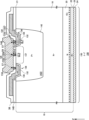
半導体装置および半導体装置の製造方法 Download PDFInfo
- Publication number
- WO2025018288A1 WO2025018288A1 PCT/JP2024/025236 JP2024025236W WO2025018288A1 WO 2025018288 A1 WO2025018288 A1 WO 2025018288A1 JP 2024025236 W JP2024025236 W JP 2024025236W WO 2025018288 A1 WO2025018288 A1 WO 2025018288A1
- Authority
- WO
- WIPO (PCT)
- Prior art keywords
- temperature
- sensitive
- trench
- contact
- region
- Prior art date
- Legal status (The legal status is an assumption and is not a legal conclusion. Google has not performed a legal analysis and makes no representation as to the accuracy of the status listed.)
- Pending
Links
Images














Classifications
-
- H—ELECTRICITY
- H10—SEMICONDUCTOR DEVICES; ELECTRIC SOLID-STATE DEVICES NOT OTHERWISE PROVIDED FOR
- H10D—INORGANIC ELECTRIC SEMICONDUCTOR DEVICES
- H10D8/00—Diodes
-
- H—ELECTRICITY
- H10—SEMICONDUCTOR DEVICES; ELECTRIC SOLID-STATE DEVICES NOT OTHERWISE PROVIDED FOR
- H10W—GENERIC PACKAGES, INTERCONNECTIONS, CONNECTORS OR OTHER CONSTRUCTIONAL DETAILS OF DEVICES COVERED BY CLASS H10
- H10W40/00—Arrangements for thermal protection or thermal control
-
- H—ELECTRICITY
- H10—SEMICONDUCTOR DEVICES; ELECTRIC SOLID-STATE DEVICES NOT OTHERWISE PROVIDED FOR
- H10D—INORGANIC ELECTRIC SEMICONDUCTOR DEVICES
- H10D12/00—Bipolar devices controlled by the field effect, e.g. insulated-gate bipolar transistors [IGBT]
- H10D12/411—Insulated-gate bipolar transistors [IGBT]
- H10D12/441—Vertical IGBTs
- H10D12/461—Vertical IGBTs having non-planar surfaces, e.g. having trenches, recesses or pillars in the surfaces of the emitter, base or collector regions
- H10D12/481—Vertical IGBTs having non-planar surfaces, e.g. having trenches, recesses or pillars in the surfaces of the emitter, base or collector regions having gate structures on slanted surfaces, on vertical surfaces, or in grooves, e.g. trench gate IGBTs
-
- H—ELECTRICITY
- H10—SEMICONDUCTOR DEVICES; ELECTRIC SOLID-STATE DEVICES NOT OTHERWISE PROVIDED FOR
- H10D—INORGANIC ELECTRIC SEMICONDUCTOR DEVICES
- H10D62/00—Semiconductor bodies, or regions thereof, of devices having potential barriers
- H10D62/10—Shapes, relative sizes or dispositions of the regions of the semiconductor bodies; Shapes of the semiconductor bodies
- H10D62/124—Shapes, relative sizes or dispositions of the regions of semiconductor bodies or of junctions between the regions
- H10D62/126—Top-view geometrical layouts of the regions or the junctions
-
- H—ELECTRICITY
- H10—SEMICONDUCTOR DEVICES; ELECTRIC SOLID-STATE DEVICES NOT OTHERWISE PROVIDED FOR
- H10D—INORGANIC ELECTRIC SEMICONDUCTOR DEVICES
- H10D8/00—Diodes
- H10D8/422—PN diodes having the PN junctions in mesas
-
- H—ELECTRICITY
- H10—SEMICONDUCTOR DEVICES; ELECTRIC SOLID-STATE DEVICES NOT OTHERWISE PROVIDED FOR
- H10D—INORGANIC ELECTRIC SEMICONDUCTOR DEVICES
- H10D84/00—Integrated devices formed in or on semiconductor substrates that comprise only semiconducting layers, e.g. on Si wafers or on GaAs-on-Si wafers
- H10D84/101—Integrated devices comprising main components and built-in components, e.g. IGBT having built-in freewheel diode
- H10D84/161—IGBT having built-in components
-
- H—ELECTRICITY
- H10—SEMICONDUCTOR DEVICES; ELECTRIC SOLID-STATE DEVICES NOT OTHERWISE PROVIDED FOR
- H10D—INORGANIC ELECTRIC SEMICONDUCTOR DEVICES
- H10D12/00—Bipolar devices controlled by the field effect, e.g. insulated-gate bipolar transistors [IGBT]
- H10D12/411—Insulated-gate bipolar transistors [IGBT]
- H10D12/417—Insulated-gate bipolar transistors [IGBT] having a drift region having a doping concentration that is higher at the collector side relative to other parts of the drift region
-
- H—ELECTRICITY
- H10—SEMICONDUCTOR DEVICES; ELECTRIC SOLID-STATE DEVICES NOT OTHERWISE PROVIDED FOR
- H10D—INORGANIC ELECTRIC SEMICONDUCTOR DEVICES
- H10D12/00—Bipolar devices controlled by the field effect, e.g. insulated-gate bipolar transistors [IGBT]
- H10D12/411—Insulated-gate bipolar transistors [IGBT]
- H10D12/418—Insulated-gate bipolar transistors [IGBT] having a drift region having a doping concentration that is higher at the emitter side relative to other parts of the drift region
-
- H—ELECTRICITY
- H10—SEMICONDUCTOR DEVICES; ELECTRIC SOLID-STATE DEVICES NOT OTHERWISE PROVIDED FOR
- H10D—INORGANIC ELECTRIC SEMICONDUCTOR DEVICES
- H10D62/00—Semiconductor bodies, or regions thereof, of devices having potential barriers
- H10D62/10—Shapes, relative sizes or dispositions of the regions of the semiconductor bodies; Shapes of the semiconductor bodies
- H10D62/102—Constructional design considerations for preventing surface leakage or controlling electric field concentration
- H10D62/103—Constructional design considerations for preventing surface leakage or controlling electric field concentration for increasing or controlling the breakdown voltage of reverse-biased devices
- H10D62/105—Constructional design considerations for preventing surface leakage or controlling electric field concentration for increasing or controlling the breakdown voltage of reverse-biased devices by having particular doping profiles, shapes or arrangements of PN junctions; by having supplementary regions, e.g. junction termination extension [JTE]
- H10D62/106—Constructional design considerations for preventing surface leakage or controlling electric field concentration for increasing or controlling the breakdown voltage of reverse-biased devices by having particular doping profiles, shapes or arrangements of PN junctions; by having supplementary regions, e.g. junction termination extension [JTE] having supplementary regions doped oppositely to or in rectifying contact with regions of the semiconductor bodies, e.g. guard rings with PN or Schottky junctions
-
- H—ELECTRICITY
- H10—SEMICONDUCTOR DEVICES; ELECTRIC SOLID-STATE DEVICES NOT OTHERWISE PROVIDED FOR
- H10D—INORGANIC ELECTRIC SEMICONDUCTOR DEVICES
- H10D62/00—Semiconductor bodies, or regions thereof, of devices having potential barriers
- H10D62/10—Shapes, relative sizes or dispositions of the regions of the semiconductor bodies; Shapes of the semiconductor bodies
- H10D62/124—Shapes, relative sizes or dispositions of the regions of semiconductor bodies or of junctions between the regions
- H10D62/126—Top-view geometrical layouts of the regions or the junctions
- H10D62/127—Top-view geometrical layouts of the regions or the junctions of cellular field-effect devices, e.g. multicellular DMOS transistors or IGBTs
-
- H—ELECTRICITY
- H10—SEMICONDUCTOR DEVICES; ELECTRIC SOLID-STATE DEVICES NOT OTHERWISE PROVIDED FOR
- H10D—INORGANIC ELECTRIC SEMICONDUCTOR DEVICES
- H10D62/00—Semiconductor bodies, or regions thereof, of devices having potential barriers
- H10D62/40—Crystalline structures
-
- H—ELECTRICITY
- H10—SEMICONDUCTOR DEVICES; ELECTRIC SOLID-STATE DEVICES NOT OTHERWISE PROVIDED FOR
- H10D—INORGANIC ELECTRIC SEMICONDUCTOR DEVICES
- H10D62/00—Semiconductor bodies, or regions thereof, of devices having potential barriers
- H10D62/50—Physical imperfections
- H10D62/53—Physical imperfections the imperfections being within the semiconductor body
-
- H—ELECTRICITY
- H10—SEMICONDUCTOR DEVICES; ELECTRIC SOLID-STATE DEVICES NOT OTHERWISE PROVIDED FOR
- H10D—INORGANIC ELECTRIC SEMICONDUCTOR DEVICES
- H10D64/00—Electrodes of devices having potential barriers
- H10D64/111—Field plates
-
- H—ELECTRICITY
- H10—SEMICONDUCTOR DEVICES; ELECTRIC SOLID-STATE DEVICES NOT OTHERWISE PROVIDED FOR
- H10D—INORGANIC ELECTRIC SEMICONDUCTOR DEVICES
- H10D64/00—Electrodes of devices having potential barriers
- H10D64/111—Field plates
- H10D64/117—Recessed field plates, e.g. trench field plates or buried field plates
Definitions
- the present invention relates to a semiconductor device and a method for manufacturing a semiconductor device.
- Patent Document 1 U.S. Patent Application Publication No. 2019/0172770
- Patent Document 2 JP 2014-053554 A
- Patent Document 3 JP 2012-195339 A
- Patent Document 4 JP 2021-015884 A
- Patent Document 5 JP 2010-287786 A
- a semiconductor device in a first aspect of the present invention, includes an active section and a temperature-sensing section, the temperature-sensing section including a temperature-sensing diode section, the temperature-sensing diode section including a temperature-sensing trench section provided on the front surface side of a semiconductor substrate, a temperature-sensing trench conductive section provided inside the temperature-sensing trench section, a first conductivity-type temperature-sensing anode region provided in the temperature-sensing trench conductive section, and a second conductivity-type temperature-sensing cathode region provided in the temperature-sensing trench conductive section and in contact with the temperature-sensing anode region to form a PN junction.
- the temperature-sensitive trench conductive portion may be filled inside the temperature-sensitive trench portion.
- the sidewall of the temperature-sensitive anode region may be in contact with the sidewall of the temperature-sensitive cathode region.
- the bottom surface of one of the temperature-sensitive anode region or the temperature-sensitive cathode region may be in contact with the top surface of the other of the temperature-sensitive anode region or the temperature-sensitive cathode region.
- the temperature-sensitive anode region may have a plurality of temperature-sensitive anode regions provided inside the trench of the temperature-sensitive trench portion.
- the temperature-sensitive cathode region may have a plurality of temperature-sensitive cathode regions provided inside the trench of the temperature-sensitive trench portion.
- the plurality of temperature-sensitive anode regions and the plurality of temperature-sensitive cathode regions may be arranged alternately inside the trench of the temperature-sensitive trench portion in a direction parallel to the front surface of the semiconductor substrate.
- the temperature-sensitive trench portion may have a trench insulating portion provided on the inner wall of the temperature-sensitive trench conductive portion inside the trench of the temperature-sensitive trench portion.
- any of the above semiconductor devices may include an interlayer insulating film provided above the active portion and the temperature-sensitive diode portion, a temperature-sensitive wiring portion electrically connected to the temperature-sensitive trench portion, and a temperature-sensitive contact portion provided in the interlayer insulating film and electrically connecting the temperature-sensitive wiring portion and the temperature-sensitive trench portion.
- the temperature-sensitive wiring portion may include an anode wiring portion electrically connected to the temperature-sensitive anode region, and a cathode wiring portion electrically connected to the temperature-sensitive cathode region.
- the temperature-sensitive contact portion may include an anode contact portion provided in the interlayer insulating film and electrically connecting the anode wiring portion and the temperature-sensitive anode region, and a cathode contact portion provided in the interlayer insulating film and electrically connecting the cathode wiring portion and the temperature-sensitive cathode region.
- the temperature sensitive trench portion may have a plurality of temperature sensitive trench portions.
- the anode contact portion may have a plurality of anode contact portions provided corresponding to the plurality of temperature sensitive trench portions, respectively.
- the cathode contact portion may have a plurality of cathode contact portions provided corresponding to the plurality of temperature sensitive trench portions, respectively.
- the anode wiring portion may be provided extending above the plurality of temperature sensitive trench portions and may be electrically connected to the plurality of anode contact portions.
- the cathode wiring portion may be provided extending above the plurality of temperature sensitive trench portions and may be electrically connected to the plurality of cathode contact portions.
- the temperature-sensitive trench portion may have a linear structure connected to the anode contact portion and the cathode contact portion.
- the temperature-sensitive trench portion may have a loop structure in which one end of the temperature-sensitive trench portion is connected to the other end.
- any of the above semiconductor devices may include a well region of a second conductivity type provided in the semiconductor substrate.
- the temperature-sensitive trench portion may be provided inside the well region when viewed from above, and at least one of the sidewalls or the bottom of the temperature-sensitive trench portion may be in contact with the well region.
- any of the above semiconductor devices may include a transition portion provided between the temperature-sensitive trench portion and the active portion.
- the transition portion may have a dummy trench portion provided on the front surface side of the semiconductor substrate.
- the transition portion may have a well region of a second conductivity type provided in the semiconductor substrate.
- the active portion may have an active trench portion provided on the front surface of the semiconductor substrate.
- the trench depth of the temperature-sensitive trench portion may be the same as the trench depth of the active trench portion.
- a semiconductor device in a second aspect of the present invention, includes an active portion provided on a semiconductor substrate, a temperature-sensing portion provided above the semiconductor substrate, and an interlayer insulating film provided above the active portion and the temperature-sensing portion, the temperature-sensing portion having a recessed region having a depression on the front surface side of the semiconductor substrate, and a temperature-sensing diode portion provided above the semiconductor substrate in the recessed region, and in the depth direction of the semiconductor substrate, the height position of the upper surface of the interlayer insulating film in the active portion is the same as the height position of the upper surface of the interlayer insulating film in the recessed region.
- the semiconductor device may include a temperature-sensitive wiring section electrically connected to the temperature-sensitive diode section, and a temperature-sensitive contact section provided in the interlayer insulating film and electrically connecting the temperature-sensitive wiring section and the temperature-sensitive diode section.
- the active portion may have an active trench portion provided on the front surface of the semiconductor substrate and an active contact portion provided above the semiconductor substrate.
- the contact width of the temperature-sensitive contact portion may be larger than the contact width of the active contact portion.
- the temperature sensing portion may have an insulating film on the upper surface of the semiconductor substrate in the recessed region.
- the temperature sensing portion may have a temperature sensing contact portion electrically connected to the temperature sensing diode portion.
- the distance from the lower end of the temperature sensing contact portion in the depth direction of the semiconductor substrate to the upper surface of the insulating film may be greater than the thickness of the insulating film.
- the temperature sensing portion may have a temperature sensing contact portion electrically connected to the temperature sensing diode portion.
- the distance from the front surface of the semiconductor substrate to the lower end of the temperature sensing contact portion may be greater than the distance from the lower end of the temperature sensing contact portion to the upper surface of the insulating film.
- the temperature sensing portion may have a temperature sensing contact portion electrically connected to the temperature sensing diode portion.
- the distance from the front surface of the semiconductor substrate to the lower end of the temperature sensing contact portion may be smaller than the distance from the lower end of the temperature sensing contact portion to the upper surface of the insulating film.
- a method for manufacturing a semiconductor device includes a step of forming an active portion and a temperature-sensing portion, and the step of forming the temperature-sensing portion includes a step of forming a temperature-sensing trench portion on the front surface side of a semiconductor substrate, a step of forming a temperature-sensing trench conductive portion inside the temperature-sensing trench portion, a step of forming a temperature-sensing anode region in the temperature-sensing trench conductive portion, and a step of forming a temperature-sensing cathode region in the temperature-sensing trench conductive portion that is in contact with the temperature-sensing anode region.
- the step of forming the active portion may include a step of forming a trench of the active trench portion on the front surface side of the semiconductor substrate.
- the trench of the temperature-sensitive trench portion and the trench of the active trench portion may be formed simultaneously by the same etching process.
- a semiconductor device in a fourth aspect of the present invention, includes an active portion and a non-active portion, the semiconductor device including an interlayer insulating film provided above the active portion and the non-active portion, the non-active portion having a recessed region having a depression on the front surface side of the semiconductor substrate, and a polycrystalline portion provided above the semiconductor substrate in the recessed region, and the height position of the upper surface of the interlayer insulating film in the active portion is the same as the height position of the upper surface of the interlayer insulating film in the recessed region in the depth direction of the semiconductor substrate.
- the inactive portion may have a first inactive contact portion provided in the interlayer insulating film above the recess region and electrically connected to the polycrystalline portion.
- the inactive portion may have an insulating film on the upper surface of the semiconductor substrate in the recess region.
- the distance from the lower end of the first inactive contact portion in the depth direction of the semiconductor substrate to the upper surface of the inactive portion insulating film may be greater than the thickness of the insulating film.
- the inactive portion may have an insulating film on the upper surface of the semiconductor substrate in the recess region. In the depth direction of the semiconductor substrate, the distance from the front surface of the semiconductor substrate to the lower end of the first inactive contact portion may be greater than the distance from the lower end of the first inactive contact portion to the upper surface of the insulating film.
- the inactive portion may have an insulating film on the upper surface of the semiconductor substrate in the recess region. In the depth direction of the semiconductor substrate, the distance from the front surface of the semiconductor substrate to the lower end of the first inactive contact portion may be smaller than the distance from the lower end of the first inactive contact portion to the upper surface of the insulating film.
- any of the above semiconductor devices may include a gate trench portion provided on the front surface of the semiconductor substrate and having a gate conductive portion, and a gate metal layer provided above the semiconductor substrate.
- the first inactive contact portion may electrically connect the gate metal layer and the polycrystalline portion.
- the polycrystalline portion may be connected to the gate conductive portion.
- the polycrystalline portion may extend to the outside of the recess region.
- the gate trench portion may be provided outside the recess region.
- any of the above semiconductor devices may include a dummy trench portion provided on the front surface of the semiconductor substrate and having a dummy conductive portion, and an emitter electrode provided above the semiconductor substrate.
- the first inactive contact portion may electrically connect the emitter electrode and the polycrystalline portion.
- the polycrystalline portion may be connected to the dummy conductive portion.
- the polycrystalline portion may extend to the outside of the recess region.
- the dummy trench portion may be provided outside the recess region.
- any of the above semiconductor devices may include a guard ring of a second conductivity type provided on the front surface of the semiconductor substrate between the active portion and an edge of the semiconductor substrate, and an edge metal layer provided above the semiconductor substrate.
- the inactive portion may have a second inactive contact portion provided in the interlayer insulating film outside the recess region and electrically connecting the edge metal layer and the guard ring.
- the first inactive contact portion may electrically connect the edge metal layer and the polycrystalline portion.
- the distance in the depth direction of the semiconductor substrate from a position where the first inactive contact portion and the edge metal layer contact to a lower end of the first inactive contact portion may be equal to the distance from a position where the second inactive contact portion and the edge metal layer contact to a lower end of the second inactive contact portion.
- the first inactive contact portion may be provided above a corner region of the guard ring.
- any of the above semiconductor devices may include a pad electrode provided above the semiconductor substrate.
- the first inactive contact portion may electrically connect the pad electrode to the polycrystalline portion.
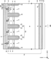
- FIG. 1 shows an example of an enlarged view of the top surface of the semiconductor device 100.
- 1A shows an example of a cross section taken along line aa' in FIG. 1A.
- 1 shows an enlarged view of the top surface of a modified example of the semiconductor device 100.
- FIG. 2B shows an example of a cross section taken along line bb' in FIG. 2A.
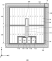
- 1 shows an example of a top view of a semiconductor device 100.
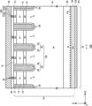
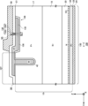
- FIG. 1 shows an example of a cross section of a semiconductor device 100 including a temperature sensing portion 180.
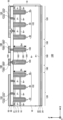
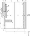
- 1 shows a cross section of a modified example of the semiconductor device 100 including a temperature sensitive portion 180.
- 1 shows a cross section of a modified example of the semiconductor device 100 including a temperature sensitive portion 180.
- 1 shows a cross section of a modified example of the semiconductor device 100 including a temperature sensitive portion 180.
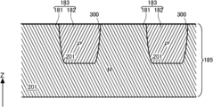
- 1 shows an example of a cross section of a temperature-sensitive trench portion 185.
- 13 shows a cross section of a modified example of the temperature sensitive trench portion 185.
- 13 shows a cross section of a modified example of the temperature sensitive trench portion 185.
- 13 shows a cross section of a modified example of the temperature sensitive trench portion 185.
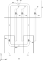
- 4 shows an example of an enlarged view of the upper surface of the temperature sensing diode portion 183 in the temperature sensing portion 180 in region T of FIG. 3.
- 13 is an enlarged top view showing another example of the temperature sensing diode portion 183 in the temperature sensing portion 180.
- FIG. 13 is an enlarged top view showing another example of the temperature sensing diode portion 183 in the temperature sensing portion 180.
- FIG. 13 is an enlarged top view showing another example of the temperature sensing diode portion 183 in the temperature sensing portion 180.
- FIG. 13 is an enlarged top view showing another example of the temperature sensing diode portion 183 in the temperature sensing portion 180.
- FIG. 6A, 6B, 6C, 6D, and 6E show equivalent circuits of the temperature sensing diode portion 183.
- FIG. 13 is an enlarged top view showing another example of the temperature sensing diode portion 183 in the temperature sensing portion 180.
- FIG. 13 is an enlarged top view showing another example of the temperature sensing diode portion 183 in the temperature sensing portion 180.
- FIG. 13 is an enlarged top view showing another example of the temperature sensing diode portion 183 in the temperature sensing portion 180.
- FIG. 13 is an enlarged top view showing another example of the temperature sensing diode portion 183 in the temperature sensing portion 180.
- FIG. 13 is an enlarged top view showing another example of the temperature sensing diode portion 183 in the temperature sensing portion 180.
- FIG. 6I is an equivalent circuit diagram of the temperature sensing diode unit 183 shown in FIG. 6J and FIG. 6K. 13 is an enlarged top view showing another example of the temperature sensing diode portion 183 in the temperature sensing portion 180.
- FIG. FIG. 6C is an equivalent circuit diagram of the temperature sensing diode unit 183 shown in FIG. 6L. 4 shows another example of an enlarged view of the upper surface of the temperature sensing diode portion 183 in the temperature sensing portion 180 in the region T of FIG.
- FIG. 3 . 6 shows an equivalent circuit of the temperature sensing diode portion 183 shown in FIG. 6N. 4 shows another example of an enlarged view of the upper surface of the temperature sensing diode portion 183 in the temperature sensing portion 180 in the region T of FIG. 3 . 6C shows an equivalent circuit of the temperature sensing diode portion 183 shown in FIG. 6P. 4 shows another example of an enlarged view of the upper surface of the temperature sensing diode portion 183 in the temperature sensing portion 180 in the region T of FIG. 3 . 1 shows a cross section of a modified example of the semiconductor device 100 including a temperature sensitive portion 180. 1 shows a cross section of a modified example of the semiconductor device 100 including a temperature sensitive portion 180.
- 1 shows a cross section of a modified example of the semiconductor device 100 including a temperature sensitive portion 180.
- 3 is a flowchart showing an example of a manufacturing process of the semiconductor device 100.
- 1 is an example of electrical connections between the various parts of the semiconductor device 100.
- 1 shows an example of an enlarged view of the top surface of the semiconductor device 100.
- 10B shows an example of a cross section taken along the line cc' in FIG. 10A.
- 10B shows an example of a cross section taken along line dd' in FIG. 10A.
- 10B shows an example of a cross section taken along line dd' in FIG. 10A.
- 10B shows an example of a cross section taken along the line ee' in FIG. 10A.
- 10B shows an example of a cross section taken along the line ee' in FIG. 10A.
- 1 shows an example of a top view of a semiconductor device 100.
- FIG. An example of the region R in FIG. 13A is shown.
- An example of the ff' cross section in FIG. 13B is shown.
- An example of the ff' cross section in FIG. 13B is shown.
- 13B shows an example of a cross section taken along line gg' in FIG. 13A.
- 13B shows an example of a cross section taken along line gg' in FIG. 13A.
- one side in a direction parallel to the depth direction of the semiconductor substrate is referred to as "upper” and the other side as “lower.”
- the upper surface is referred to as the upper surface and the other surface is referred to as the lower surface.
- the directions of "upper” and “lower” are not limited to the direction of gravity or the directions when the semiconductor device is mounted.
- the orthogonal coordinate axes merely identify the relative positions of components, and do not limit a specific direction.
- the Z-axis does not limit the height direction relative to the ground.
- the +Z-axis direction and the -Z-axis direction are opposite directions.
- the Z-axis direction is described without indicating positive or negative, it means the direction parallel to the +Z-axis and -Z-axis.
- the orthogonal axes parallel to the top and bottom surfaces of the semiconductor substrate are referred to as the X-axis and Y-axis.
- the axis perpendicular to the top and bottom surfaces of the semiconductor substrate is referred to as the Z-axis.
- the direction of the Z-axis may be referred to as the depth direction.
- the direction parallel to the top and bottom surfaces of the semiconductor substrate, including the X-axis and Y-axis may be referred to as the horizontal direction.
- the conductivity type of a doped region doped with impurities is described as P type or N type.
- impurities may specifically mean either N type donors or P type acceptors, and may be described as dopants.
- doping means introducing donors or acceptors into a semiconductor substrate to make it a semiconductor that exhibits N type conductivity or a semiconductor that exhibits P type conductivity.
- the doping concentration refers to the donor concentration or acceptor concentration in a thermal equilibrium state.
- the net doping concentration refers to the net concentration obtained by adding together the donor concentration, which is the concentration of positive ions, and the acceptor concentration, which is the concentration of negative ions, including the polarity of the charge.
- the donor concentration is ND and the acceptor concentration is NA
- the net doping concentration at any position is ND-NA.
- the net doping concentration may be simply referred to as the doping concentration.
- Donors have the function of supplying electrons to a semiconductor. Acceptors have the function of receiving electrons from a semiconductor. Donors and acceptors are not limited to impurities themselves.
- VOH defects in semiconductors that combine vacancies (V), oxygen (O), and hydrogen (H) Si-i-H defects in semiconductors that combine interstitial silicon (Si-i) and hydrogen
- CiOi-H defects in semiconductors that combine interstitial carbon (Ci), interstitial oxygen (Oi), and hydrogen function as donors that supply electrons.
- these VOH defects may be referred to as hydrogen donors.
- chemical concentration refers to the concentration atomic density of impurities measured regardless of the state of electrical activation.
- the chemical concentration can be measured, for example, by secondary ion mass spectrometry (SIMS).
- the above-mentioned net doping concentration can be measured by voltage-capacitance measurement (CV method).
- the carrier concentration measured by spreading resistance measurement (SR method) may be the net doping concentration.
- Carriers refer to charge carriers of electrons or holes.
- the carrier concentration measured by the CV method or SR method may be a value in a thermal equilibrium state.
- the carrier concentration in that region may be the donor concentration.
- the carrier concentration in that region may be the acceptor concentration.
- the doping concentration in an N-type region may be referred to as the donor concentration
- the doping concentration in a P-type region may be referred to as the acceptor concentration.
- the peak value may be taken as the concentration of the donor, acceptor or net doping in the region.
- the average value of the concentration of the donor, acceptor or net doping in the region may be taken as the concentration of the donor, acceptor or net doping.
- the carrier concentration measured by the SR method may be lower than the donor or acceptor concentration.
- the carrier mobility of the semiconductor substrate may be lower than the value in the crystalline state.
- the decrease in carrier mobility occurs when the carriers are scattered due to a disturbance (disorder) in the crystal structure caused by lattice defects, etc.
- the reason for the decrease in carrier concentration is as follows.
- the spreading resistance is measured and the carrier concentration is calculated from the measured value of the spreading resistance.
- the mobility in the crystalline state is used as the carrier mobility.
- the carrier concentration is calculated based on the carrier mobility in the crystalline state, even though the carrier mobility is decreased. Therefore, the value is lower than the actual carrier concentration, i.e., the concentration of the donor or acceptor.
- the donor or acceptor concentration calculated from the carrier concentration measured by the CV method or the SR method may be lower than the chemical concentration of the element indicating the donor or acceptor.
- the donor concentration of phosphorus or arsenic, which is a donor in a silicon semiconductor, or the acceptor concentration of boron, which is an acceptor is about 99% of these chemical concentrations.
- the donor concentration of hydrogen, which is a donor in a silicon semiconductor is about 0.1% to 10% of the chemical concentration of hydrogen.
- the SI system of units is adopted.
- the unit of distance or length may be expressed in cm (centimeter). In this case, various calculations may be calculated by converting it to m (meter).
- the numerical representation of powers of 10 for example, the representation of 1E+16 indicates 1 ⁇ 10 16 , and the representation of 1E-16 indicates 1 ⁇ 10 -16 .
- FIG. 1A shows an example of an enlarged view of the top surface of a semiconductor device 100.
- the semiconductor device 100 in this example is a semiconductor chip that includes a transistor portion 70.
- the semiconductor device 100 is not limited to a transistor, as long as it is a semiconductor element having a MOS gate structure on a semiconductor substrate 10.
- the transistor portion 70 is a region obtained by projecting the collector region 22 provided on the back side of the semiconductor substrate 10 onto the upper surface of the semiconductor substrate 10.
- the collector region 22 will be described later.
- the transistor portion 70 includes a transistor such as an IGBT.
- the transistor portion 70 is an IGBT.
- the transistor portion 70 may be another type of transistor, such as a MOSFET.
- an edge termination structure may be provided in the area on the negative side in the Y-axis direction of the semiconductor device 100 in this example.
- the edge termination structure relieves electric field concentration on the upper surface side of the semiconductor substrate 10.
- the edge termination structure has, for example, a guard ring, a field plate, a resurf, or a structure that combines these. Note that in this example, for convenience, the edge on the negative side in the Y-axis direction is described, but the same applies to other edges of the semiconductor device 100.
- the semiconductor substrate 10 is a substrate formed of a semiconductor material.
- the semiconductor substrate 10 may be a silicon substrate, a silicon carbide substrate, another compound semiconductor substrate, or a diamond semiconductor substrate.
- the semiconductor substrate 10 is a silicon substrate. Note that in this specification, when the term "top view” is used, it means that the semiconductor substrate 10 is viewed from the top side.
- the semiconductor substrate 10 has a front surface 21 and a back surface 23, as described below.
- the semiconductor device 100 of this example includes a gate trench portion 40, a dummy trench portion 30, an emitter region 12, a base region 14, a contact region 15, and a well region 17 on the front surface 21 of the semiconductor substrate 10.
- the semiconductor device 100 of this example also includes an emitter electrode 52 and a gate metal layer 50 provided above the front surface 21 of the semiconductor substrate 10.
- the emitter electrode 52 and the gate metal layer 50 are an example of a front surface side metal layer.
- the gate trench portion 40 is an example of a MOS gate structure included in the semiconductor device 100. Note that the semiconductor device 100 of this example is a transistor with a MOS gate structure, but may also be a diode with a MOS gate structure.
- the emitter electrode 52 is provided above the gate trench portion 40, the dummy trench portion 30, the emitter region 12, the base region 14, the contact region 15, and the well region 17.
- the gate metal layer 50 is provided above the connection portion 25 and the well region 17.
- the emitter electrode 52 and the gate metal layer 50 are formed of a material containing a metal. At least a portion of the emitter electrode 52 may be formed of a metal such as aluminum (Al) or a metal alloy such as aluminum-silicon alloy (AlSi) or aluminum-silicon-copper alloy (AlSiCu). At least a portion of the gate metal layer 50 may be formed of a metal such as aluminum (Al) or a metal alloy such as aluminum-silicon alloy (AlSi) or aluminum-silicon-copper alloy (AlSiCu). The emitter electrode 52 and the gate metal layer 50 may have a barrier metal film made of titanium or a titanium compound under the region made of aluminum or the like. The emitter electrode 52 and the gate metal layer 50 are provided separately from each other.
- the emitter electrode 52 and the gate metal layer 50 are provided above the semiconductor substrate 10 with the interlayer insulating film 38 in between.
- the interlayer insulating film 38 is omitted in FIG. 1A.
- the interlayer insulating film 38 has contact holes 54, 55, and 56 penetrating therethrough.
- the contact hole 55 electrically connects the gate metal layer 50 and the gate conductive portion in the transistor portion 70 via the connection portion 25. Inside the contact hole 55, a barrier metal film made of titanium or a titanium compound and/or a plug portion made of tungsten may be formed.
- the contact hole 56 connects the emitter electrode 52 to the dummy conductive portion in the dummy trench portion 30. Inside the contact hole 56, a barrier metal film made of titanium or a titanium compound and/or a plug portion made of tungsten may be formed.
- connection portion 25 is connected to the front surface side metal layer such as the emitter electrode 52 or the gate metal layer 50.
- the connection portion 25 is provided between the gate metal layer 50 and the gate conductive portion.
- the connection portion 25 in this example may be provided extending in the X-axis direction and electrically connected to the gate conductive portion.
- the connection portion 25 may also be provided between the emitter electrode 52 and the dummy conductive portion. In this example, the connection portion 25 is not provided between the emitter electrode 52 and the dummy conductive portion.
- the connection portion 25 is a conductive material such as polysilicon doped with impurities.
- the connection portion 25 in this example is polysilicon (N+) doped with N-type impurities.
- the connection portion 25 is provided above the front surface 21 of the semiconductor substrate 10 via an insulating film such as an oxide film.
- the gate trench portion 40 is an example of an active trench portion 122 provided on the front surface 21 of the semiconductor substrate 10. That is, the active trench portion 122 may be a trench portion provided in the active portion 120. The active trench portion 122 will be described later.
- the gate trench portion 40 is arranged at predetermined intervals along a predetermined arrangement direction (the X-axis direction in this example).
- the gate trench portion 40 in this example may have two extension portions 41 that extend parallel to the front surface 21 of the semiconductor substrate 10 and along an extension direction perpendicular to the arrangement direction (the Y-axis direction in this example), and a connection portion 43 that connects the two extension portions 41.
- connection portion 43 is formed in a curved shape.
- the gate metal layer 50 may be electrically connected to the gate conductive portion via the connection portion 25.
- the dummy trench portion 30 is an example of an active trench portion 122 provided on the front surface 21 of the semiconductor substrate 10. That is, the active trench portion 122 may be a trench portion provided in the active portion 120.
- the dummy trench portion 30 is a trench portion electrically connected to the emitter electrode 52.
- the dummy trench portion 30 is arranged at predetermined intervals along a predetermined arrangement direction (the X-axis direction in this example).
- the dummy trench portion 30 in this example has an I-shape on the front surface 21 of the semiconductor substrate 10, but may have a U-shape on the front surface 21 of the semiconductor substrate 10 like the gate trench portion 40. That is, the dummy trench portion 30 may have two extension portions extending along the extension direction and a connection portion connecting the two extension portions.
- the transistor section 70 in this example has a structure in which two gate trench sections 40 and two dummy trench sections 30 are arranged in a repeated manner. That is, the transistor section 70 in this example has gate trench sections 40 and dummy trench sections 30 in a 1:1 ratio. For example, the transistor section 70 has one dummy trench section 30 between two extension sections 41.
- the ratio of the gate trench portions 40 to the dummy trench portions 30 is not limited to this example.
- the ratio of the gate trench portions 40 may be greater than the ratio of the dummy trench portions 30, and the ratio of the dummy trench portions 30 may be greater than the ratio of the gate trench portions 40.
- the ratio of the gate trench portions 40 to the dummy trench portions 30 may be 2:3 or 2:4.
- the transistor portion 70 may not have dummy trench portions 30, with all trench portions being gate trench portions 40.
- the well region 17 is a second conductivity type region provided on the front surface 21 side of the semiconductor substrate 10 relative to the drift region 18 described later.
- the well region 17 is an example of a well region provided on the peripheral side of the active section 120.
- the well region 17 is a P+ type, for example.
- the well region 17 is formed in a predetermined range from the end of the active region on the side where the gate metal layer 50 is provided.
- the diffusion depth of the well region 17 may be deeper than the depth of the gate trench portion 40 and the dummy trench portion 30.
- a portion of the gate trench portion 40 and the dummy trench portion 30 on the gate metal layer 50 side is formed in the well region 17.
- the bottom of the end of the gate trench portion 40 and the dummy trench portion 30 in the extension direction may be covered by the well region 17.
- the contact holes 54 are formed above the emitter region 12 and the contact region 15 in the transistor section 70.
- the contact holes 54 are not provided above the well regions 17 provided at both ends in the Y-axis direction. In this manner, one or more contact holes 54 are formed in the interlayer insulating film.
- the one or more contact holes 54 may be provided extending in the extension direction.
- the mesa portion 71 is provided in the transistor portion 70 adjacent to at least one of the dummy trench portion 30 or the gate trench portion 40.
- the mesa portion 71 has a well region 17, an emitter region 12, a base region 14, and a contact region 15 on the front surface 21 of the semiconductor substrate 10.
- the emitter regions 12 and the contact regions 15 are provided alternately in the extension direction.
- the emitter region 12 is a region of the first conductivity type having a higher doping concentration than the drift region 18.
- the emitter region 12 is, for example, N+ type.
- One example of a dopant for the emitter region 12 is arsenic (As).
- the emitter region 12 is provided in contact with the gate trench portion 40 on the front surface 21 of the mesa portion 71.
- the emitter region 12 may be provided extending in the X-axis direction from one of the two trench portions sandwiching the mesa portion 71 to the other.
- the emitter region 12 is also provided below the contact hole 54.
- the emitter region 12 may or may not be in contact with the dummy trench portion 30.
- the emitter region 12 is in contact with the dummy trench portion 30.
- the contact region 15 is a second conductive type region that is provided above the base region 14 and has a higher doping concentration than the base region 14.
- the contact region 15 is of P+ type, for example.
- the contact region 15 is provided on the front surface 21 of the mesa portion 71.
- the contact region 15 may be provided in the X-axis direction from one of the two trench portions sandwiching the mesa portion 71 to the other.
- the contact region 15 may or may not contact the gate trench portion 40 or the dummy trench portion 30.
- the contact region 15 contacts the dummy trench portion 30 and the gate trench portion 40.
- the contact region 15 is also provided below the contact hole 54.
- the gate trench portion 40, the dummy trench portion 30, the emitter region 12, the contact region 15, and other configurations may be formed periodically or continuously in the +X-axis direction and the -X-axis direction (not shown).
- FIG. 1B shows an example of the a-a' cross section in FIG. 1A.
- the a-a' cross section is an XZ plane passing through the emitter region 12 in the transistor section 70.
- the semiconductor device 100 of this example has a semiconductor substrate 10, an interlayer insulating film 38, an emitter electrode 52, a collector electrode 24, and an active contact section 124.
- the collector electrode 24 is an example of a backside metal layer provided in contact with the back surface 23 of the semiconductor substrate 10.
- the emitter electrode 52 is formed above the semiconductor substrate 10 and the interlayer insulating film 38.
- the drift region 18 is a region of a first conductivity type provided in the semiconductor substrate 10.
- the drift region 18 is, as an example, N-type.
- the drift region 18 may be a region remaining in the semiconductor substrate 10 without other doped regions being formed therein.
- the doping concentration of the drift region 18 may be the doping concentration of the semiconductor substrate 10.
- the buffer region 20 is a region of a first conductivity type provided on the back surface 23 side of the semiconductor substrate 10 relative to the drift region 18.
- the buffer region 20 is, as an example, an N-type.
- the doping concentration of the buffer region 20 is higher than the doping concentration of the drift region 18.
- the buffer region 20 may function as a field stop layer that prevents the depletion layer spreading from the lower surface side of the base region 14 from reaching the collector region 22 of the second conductivity type.
- the buffer region 20 may be omitted.
- the collector region 22 is provided below the buffer region 20 in the transistor section 70.
- the collector region 22 has the second conductivity type.
- the collector region 22 is, as an example, a P+ type.
- the collector electrode 24 is formed on the rear surface 23 of the semiconductor substrate 10.
- the collector electrode 24 is formed of a conductive material such as a metal.
- the material of the collector electrode 24 may be the same as or different from the material of the emitter electrode 52.
- the base region 14 is a second conductivity type region provided above the drift region 18.
- the base region 14 is provided in contact with the gate trench portion 40.
- the base region 14 may be provided in contact with the dummy trench portion 30.
- the emitter region 12 is provided above the base region 14.
- the emitter region 12 is provided between the base region 14 and the front surface 21.
- the emitter region 12 is provided in contact with the gate trench portion 40.
- the emitter region 12 may or may not be in contact with the dummy trench portion 30.
- the accumulation region 16 is a region of a first conductivity type that is provided closer to the front surface 21 of the semiconductor substrate 10 than the drift region 18.
- the accumulation region 16 is an N+ type, for example.
- the accumulation region 16 does not necessarily have to be provided.
- the accumulation region 16 is provided in contact with the gate trench portion 40.
- the accumulation region 16 may or may not be in contact with the dummy trench portion 30.
- the doping concentration of the accumulation region 16 is higher than the doping concentration of the drift region 18.
- the dose of ion implantation of the accumulation region 16 may be 1.0E+12 cm ⁇ 2 or more and 1.0E+13 cm ⁇ 2 or less.
- the dose of ion implantation of the accumulation region 16 may be 3.0E+12 cm ⁇ 2 or more and 6.0E+12 cm ⁇ 2 or less.
- Each trench portion may be an active trench portion 122 of the active portion 120.
- Each trench portion is provided from the front surface 21 to the drift region 18. In the region where at least one of the emitter region 12, the base region 14, the contact region 15, and the accumulation region 16 is provided, each trench portion also penetrates these regions to reach the drift region 18.
- the trench portion penetrating the doping region is not limited to being manufactured in the order of forming the doping region and then the trench portion.
- the trench portion penetrating the doping region also includes a trench portion formed after the trench portion is formed.
- the gate trench portion 40 has a gate trench, a gate insulating film 42, and a gate conductive portion 44 formed on the front surface 21.
- the gate insulating film 42 is formed to cover the inner wall of the gate trench.
- the gate insulating film 42 may be formed by oxidizing or nitriding the semiconductor on the inner wall of the gate trench.
- the gate conductive portion 44 is formed inside the gate trench, further inside than the gate insulating film 42.
- the gate insulating film 42 insulates the gate conductive portion 44 from the semiconductor substrate 10.
- the gate conductive portion 44 is formed of a conductive material such as polysilicon.
- the gate trench portion 40 is covered by an interlayer insulating film 38 on the front surface 21.
- the gate conductive portion 44 includes a region facing the adjacent base region 14 on the mesa portion 71 side across the gate insulating film 42 in the depth direction of the semiconductor substrate 10. When a predetermined voltage is applied to the gate conductive portion 44, a channel is formed by an electron inversion layer on the surface layer of the interface of the base region 14 that contacts the gate trench.
- the dummy trench portion 30 may have the same structure as the gate trench portion 40.
- the dummy trench portion 30 has a dummy trench, a dummy insulating film 32, and a dummy conductive portion 34 formed on the front surface 21 side.
- the dummy insulating film 32 is formed to cover the inner wall of the dummy trench.
- the dummy conductive portion 34 is formed inside the dummy trench and is formed further inward than the dummy insulating film 32.
- the dummy insulating film 32 insulates the dummy conductive portion 34 from the semiconductor substrate 10.
- the dummy trench portion 30 may be covered by an interlayer insulating film 38 on the front surface 21.
- the interlayer insulating film 38 is provided above the semiconductor substrate 10.
- the interlayer insulating film 38 is provided in contact with the front surface 21.
- An emitter electrode 52 is provided above the interlayer insulating film 38.
- the interlayer insulating film 38 is provided with one or more contact holes 54 for electrically connecting the emitter electrode 52 to the semiconductor substrate 10.
- the contact holes 55 and 56 may also be provided penetrating the interlayer insulating film 38.
- the interlayer insulating film 38 may be a boro-phospho silicate glass (BPSG) film, a boro-silicate glass (BSG) film, a phosphosilicate glass (PSG) film, an HTO film, or a laminate of these materials.
- the thickness of the interlayer insulating film 38 is, for example, 1.0 ⁇ m, but is not limited to this.
- the active contact portion 124 is provided above the semiconductor substrate 10.
- the active contact portion 124 may have a contact hole 54 and a metal layer filled inside the contact hole 54.
- the inside of the contact hole 54 may be filled with the same material as the emitter electrode 52, or may be filled with a material different from the emitter electrode 52.
- the active contact portion 124 may include a barrier metal film 1242 provided in the contact hole 54 and in contact with the semiconductor substrate 10.
- the active contact portion 124 may include a plug portion 1244 provided in contact with the barrier metal film 1242 and filling the contact hole 54.
- the barrier metal film 1242 of the active contact portion 124 may include titanium or a titanium compound, etc.
- the plug portion 1244 of the active contact portion 124 may include a plug metal such as tungsten.
- the contact holes 55 and 56, and the metal layer filled inside the contact holes 55 and 56 may be active contact portions 124. That is, the active contact portions 124 may be provided above the active portion 120 and electrically connect the front surface side metal layer to the semiconductor substrate 10 and/or the active trench portion 122.
- An alloy layer may be formed in contact with the barrier metal film 1242, and made of an alloy of the metal contained in the barrier metal film 1242 and the layer of the semiconductor substrate 10 or the like below the contact hole 54. Also, a region with a high impurity concentration may be formed in the layer of the semiconductor substrate 10 or the like below the contact hole 54 at a location in contact with the alloy layer.
- the back side lifetime control region 151 may be provided in the transistor section 70. However, the back side lifetime control region 151 may be omitted.
- the back side lifetime control region 151 is a region in which a lifetime killer is intentionally formed by injecting impurities into the semiconductor substrate 10. In one example, the back side lifetime control region 151 is formed by injecting helium into the semiconductor substrate 10. The back side lifetime control region 151 may also be formed by injecting protons.
- the lifetime killer is a carrier recombination center.
- the lifetime killer may be a lattice defect.
- the lifetime killer may be a vacancy, a divacancy, a compound defect of these with the elements that make up the semiconductor substrate 10, or a dislocation.
- the lifetime killer may also be a rare gas element such as helium or neon, or a metal element such as platinum.
- An electron beam or protons may be used to form the lattice defect.
- the lifetime killer concentration is the concentration of carrier recombination centers.
- the lifetime killer concentration may be the concentration of lattice defects.
- the lifetime killer concentration may be the concentration of vacancies such as vacancies and divacancies, or may be the concentration of complex defects between these vacancies and the elements that make up the semiconductor substrate 10, or may be the dislocation concentration.
- the lifetime killer concentration may also be the chemical concentration of a rare gas element such as helium or neon, or may be the chemical concentration of a metal element such as platinum.
- the back side lifetime control region 151 may be formed by injection from the back side 23. This makes it easier to avoid any effects on the front surface 21 side of the semiconductor device 100.
- the back side lifetime control region 151 is formed by irradiating helium or protons from the back side 23.
- whether the back side lifetime control region 151 is formed by injection from the front surface 21 side or the back surface 23 side can be determined by obtaining the state of the front surface 21 side using the SR method or by measuring leakage current.
- FIG. 2A shows an enlarged view of the top surface of a modified example of the semiconductor device 100.
- the semiconductor device 100 of this example includes a transistor portion 70 and a diode portion 80.
- the semiconductor device 100 of this example includes a gate trench portion 40, a dummy trench portion 30, an emitter region 12, a base region 14, a contact region 15, and a well region 17 provided inside the front surface 21 side of the semiconductor substrate 10.
- the gate trench portion 40 and the dummy trench portion 30 are each an example of an active trench portion 122.
- the dummy trench portion 30 in this example may have a U-shape on the front surface 21 of the semiconductor substrate 10, similar to the gate trench portion 40. That is, the dummy trench portion 30 may have two extension portions 31 that extend along the extension direction and a connection portion 33 that connects the two extension portions 31.
- the semiconductor device 100 of this example includes an emitter electrode 52 and a gate metal layer 50 provided above the front surface 21 of the semiconductor substrate 10.
- the emitter electrode 52 and the gate metal layer 50 are provided separately from each other.
- the transistor section 70 of this example includes a boundary section 90 located at the boundary between the transistor section 70 and the diode section 80. However, the semiconductor device 100 does not need to include the boundary section 90.
- the boundary portion 90 is a region provided in the transistor portion 70 and adjacent to the diode portion 80.
- the boundary portion 90 has a contact region 15 on the front surface 21 of the semiconductor substrate 10.
- the boundary portion 90 does not have an emitter region 12.
- the trench portion of the boundary portion 90 is a dummy trench portion 30.
- the boundary portion 90 is arranged so that both ends in the X-axis direction are dummy trench portions 30.
- the contact holes 54 are provided above the base region 14 in the diode section 80.
- the contact holes 54 are provided above the contact region 15 in the boundary section 90. None of the contact holes 54 are provided above the well regions 17 provided at both ends in the Y-axis direction.
- the mesa portion 91 is provided in the boundary portion 90.
- the mesa portion 91 has a contact region 15 on the front surface 21 of the semiconductor substrate 10.
- the mesa portion 91 has a base region 14 and a well region 17 on the negative side in the Y-axis direction.
- the mesa portion 81 is provided in a region of the diode portion 80 that is sandwiched between adjacent dummy trench portions 30.
- the mesa portion 81 has a base region 14 on the front surface 21 of the semiconductor substrate 10.
- the mesa portion 81 has a well region 17 on the negative side in the Y-axis direction.
- the emitter region 12 is provided in the mesa portion 71, but does not have to be provided in the mesa portion 81 and the mesa portion 91.
- the contact region 15 is provided in the mesa portion 71 and the mesa portion 91, but does not have to be provided in the mesa portion 81.
- FIG. 2B shows an example of the b-b' cross section in FIG. 2A.
- the semiconductor device 100 of this example has a back surface side lifetime control region 151 and a front surface side lifetime control region 152. However, the semiconductor device 100 does not have to have either the back surface side lifetime control region 151 or the front surface side lifetime control region 152.
- the semiconductor device 100 of this example has a collector region 22 and a cathode region 82 on the back surface 23 side of the buffer region 20.
- the contact region 15 is provided above the base region 14 in the mesa portion 91.
- the contact region 15 is provided in contact with the dummy trench portion 30 in the mesa portion 91.
- the contact region 15 may be provided on the front surface 21 of the mesa portion 71.
- the accumulation region 16 is provided in the transistor section 70 and the diode section 80.
- the accumulation region 16 is provided on the entire surface of the transistor section 70 and the diode section 80.
- the accumulation region 16 does not have to be provided in the diode section 80.
- the cathode region 82 is provided below the buffer region 20 in the diode section 80.
- the boundary between the collector region 22 and the cathode region 82 is the boundary between the transistor section 70 and the diode section 80. That is, the collector region 22 is provided below the boundary section 90 in this example.
- the back side lifetime control region 151 may be provided in both the transistor portion 70 and the diode portion 80, or may be provided only in the transistor portion 70, or may be provided only in the diode portion 80. This allows the semiconductor device 100 of this example to speed up the turn-off operation of the transistor portion 70 or the reverse recovery operation in the diode portion 80, thereby further improving switching loss.
- the back side lifetime control region 151 may be formed by a method similar to that of the back side lifetime control region 151 of the other embodiments.
- the front surface side lifetime control region 152 is provided on the front surface 21 side of the center of the semiconductor substrate 10 in the depth direction of the semiconductor substrate 10. In this example, the front surface side lifetime control region 152 is provided in the drift region 18.
- the front surface side lifetime control region 152 may be provided in both the transistor portion 70 and the diode portion 80, or may be provided only in the diode portion 80.
- the front surface side lifetime control region 152 is provided in the diode portion 80 and the boundary portion 90, and may not be provided in a part of the transistor portion 70.
- the front surface side lifetime control region 152 can suppress the injection of holes from the transistor portion 70 and the diode portion 80, thereby reducing reverse recovery loss.
- the front surface side lifetime control region 152 may be formed by any of the methods for forming the back surface side lifetime control region 151.
- the elements and dose amounts for forming the back surface side lifetime control region 151 and the front surface side lifetime control region 152 may be the same or different.
- the front surface side lifetime control region 152 is provided by extending from the diode section 80 to the transistor section 70.
- the front surface side lifetime control region 152 may be formed by introducing a lifetime killer from the front surface 21 of the semiconductor substrate 10.
- the front surface side lifetime control region 152 may be formed by irradiation from the back surface 23 side of the semiconductor substrate 10.
- the front surface side lifetime control region 152 is provided below the gate trench section 40.
- the semiconductor device 100 may be a power semiconductor device for controlling power, etc.
- the semiconductor device 100 of this example may have a vertical semiconductor structure with a backside metal layer on the backside 23 side of the semiconductor substrate 10.
- the semiconductor device 100 may also have a horizontal semiconductor structure without a metal layer on the backside 23 side.
- an RC-IGBT with a trench gate structure is described as an example of the semiconductor device 100.
- the semiconductor device 100 may be a semiconductor device with a planar gate structure, or may be another semiconductor device such as a diode.
- the semiconductor device 100 may include an N-channel MOSFET or a P-channel MOSFET.
- FIG. 3 shows an example of a top view of the semiconductor device 100.
- the semiconductor device 100 in this example includes a temperature-sensing unit 180. In this example, only some of the components of the semiconductor device 100 are shown, and some components are omitted.
- the semiconductor substrate 10 has end edges 102 when viewed from above.
- the semiconductor substrate 10 has two sets of end edges 102 that face each other when viewed from above.
- the X-axis and the Y-axis are parallel to one of the end edges 102.
- the semiconductor substrate 10 has an active portion 120.
- the active portion 120 is a region through which a main current flows in the depth direction between the front surface 21 and the back surface 23 of the semiconductor substrate 10 when the semiconductor device 100 is in operation.
- An emitter electrode 52 is provided above the active portion 120, but is omitted in this figure.
- the active section 120 may be provided with at least one of a transistor section 70 including a transistor element such as an IGBT and a diode section 80 including a diode element such as a free wheel diode (FWD).
- the transistor section 70 and the diode section 80 are alternately arranged along a predetermined arrangement direction (the X-axis direction in this example) on the front surface 21 of the semiconductor substrate 10.
- the active section 120 may be provided with only one of the transistor section 70 and the diode section 80. That is, the active section 120 may be provided with only the transistor section 70 as shown in FIG. 1A, may be provided with both the transistor section 70 and the diode section 80 as shown in FIG. 2A, or may be provided with only the diode section 80.
- the region in which the transistor section 70 is disposed is marked with the symbol "I”
- the region in which the diode section 80 is disposed is marked with the symbol "F”.
- the transistor section 70 and the diode section 80 may each have a longitudinal direction in the extension direction. That is, the length of the transistor section 70 in the Y-axis direction is greater than its width in the X-axis direction. Similarly, the length of the diode section 80 in the Y-axis direction is greater than its width in the X-axis direction.
- the extension direction of the transistor section 70 and the diode section 80 may be the same as the longitudinal direction of the active trench section 122.
- the diode section 80 may be a region obtained by projecting a cathode region 82 provided on the rear surface 23 side of the semiconductor substrate 10 onto the upper surface of the semiconductor substrate 10.
- the region obtained by projecting the cathode region 82 onto the upper surface of the semiconductor substrate 10 may be located inside the diode section 80.
- a P+ type collector region 22 may be provided in the region other than the cathode region 82 on the rear surface 23 of the semiconductor substrate 10.
- the edge termination structure 140 is provided on the front surface 21 of the semiconductor substrate 10. When viewed from above, the edge termination structure 140 is provided between the active section 120 and the edge 102. The edge termination structure 140 relieves electric field concentration on the front surface 21 side of the semiconductor substrate 10.
- the edge termination structure 140 may include at least one of a guard ring, a field plate, and a resurf that are provided in a ring shape surrounding the active section 120.
- the semiconductor device 100 may have one or more pads above the semiconductor substrate 10.
- the semiconductor device 100 of this example includes a gate pad 112, a sense electrode 114, an anode pad 116, and a cathode pad 118.
- Each pad may be located near an edge 102 of the semiconductor substrate 10. The vicinity of the edge 102 refers to the area between the edge 102 and the emitter electrode 52 in a top view.
- each pad may be connected to an external circuit via wiring such as a wire.
- a gate potential is applied to the gate pad 112.
- the gate pad 112 is electrically connected to the gate conductive portion 44 of the gate trench portion 40 of the active portion 120.
- the semiconductor device 100 may include a gate wiring that connects the gate pad 112 and the gate trench portion 40.
- the gate wiring may be configured by appropriately combining either the gate metal layer 50 or the connection portion 25, or both.
- the sense electrode 114 is electrically connected to a current sense section 115 provided below the sense electrode 114.
- the sense electrode 114 detects the current flowing through the current sense section 115.
- the current sense section 115 detects the current flowing through the transistor section 70.
- the current sense section 115 has a structure corresponding to the transistor section 70.
- the current flowing through the current sense section 115 is smaller than the current flowing through the transistor section 70.
- a current proportional to the current flowing through the transistor section 70 may flow through the current sense section 115, simulating the operation of the transistor section 70.
- the ratio of the current flowing through the current sense section 115 to the current flowing through the transistor section 70 is appropriately set.
- the current flowing through the transistor section 70 can be monitored by using the current sense section 115.
- the temperature sensing section 180 is provided on or inside the semiconductor substrate 10. In this example, the temperature sensing section 180 is provided between the transistor sections 70 in the center of the semiconductor device 100. The temperature sensing section 180 detects the temperature of the active section 120.
- the temperature sensing section 180 may have a diode formed of monocrystalline or polycrystalline silicon.
- the temperature sensing section 180 is used to detect the temperature of the semiconductor device 100 and protect the semiconductor chip (semiconductor substrate 10) from overheating.
- the temperature sensing section 180 is connected to a constant current source. When the temperature of the semiconductor device 100 changes, the forward voltage of the current flowing through the temperature sensing section 180 changes. The semiconductor device 100 can detect the temperature based on the change in the forward voltage of the temperature sensing section 180.
- the anode pad 116 is electrically connected to the temperature-sensitive anode region 182 of the temperature-sensitive section 180.
- the anode pad 116 is electrically connected to the temperature-sensitive anode region 182 of the temperature-sensitive section 180 by the anode wiring section 117, which is electrically connected to the temperature-sensitive anode region 182.
- the temperature-sensitive anode region 182 will be described later.
- the cathode pad 118 is electrically connected to the temperature-sensing cathode region 181 of the temperature-sensing section 180.
- the cathode pad 118 is electrically connected to the temperature-sensing cathode region 181 of the temperature-sensing section 180 by a cathode wiring section 119 that is electrically connected to the temperature-sensing cathode region 181.
- the temperature-sensing cathode region 181 will be described later.
- FIG. 4A shows an example of a cross section of a semiconductor device 100 including a temperature sensing portion 180.
- the semiconductor device 100 may include a transition portion 190.
- the temperature sensing portion 180 may include a temperature sensing diode portion 183, a temperature sensing trench portion 185, a temperature sensing contact portion 188, and a temperature sensing wiring portion 189.
- the temperature sensing wiring portion 189 may include at least one of the anode wiring portion 117 or the cathode wiring portion 119.
- the temperature sensing portion 180 and the transition portion 190 may have a base region 14. This makes it possible to prevent electric field concentration in the temperature sensing trench portion 185 of the temperature sensing portion 180.
- the temperature sensing portion 180 and the transition portion 190 may or may not have an accumulation region 16.
- the temperature sensitive diode section 183 has a temperature sensitive trench conductive section 201 inside the trench.
- the temperature sensitive trench conductive section 201 is formed of a conductive material such as polysilicon.
- the temperature sensitive trench conductive section 201 has a temperature sensitive cathode region 181 and a temperature sensitive anode region 182.
- the temperature sensitive diode section 183 may be a PN diode having a PN junction 300 where the temperature sensitive cathode region 181 and the temperature sensitive anode region 182 are in contact.
- the temperature sensitive cathode region 181 and the temperature sensitive anode region 182 will be described later.
- the temperature-sensitive trench portion 185 is provided on the front surface 21 side of the semiconductor substrate.
- the temperature-sensitive trench portion 185 may have a trench insulation portion 184 that covers the inner wall of the trench.
- the trench insulation portion 184 may be a semiconductor oxide film or a semiconductor nitride film. In other words, the trench insulation portion 184 may be formed by oxidizing or nitriding the semiconductor on the inner wall of the trench.
- the trench insulation portion 184 prevents the temperature-sensitive cathode region 181 and the temperature-sensitive anode region 182 from being electrically connected to the p-type region or n-type region formed in the semiconductor substrate 10.
- the trench depth Dd of the temperature sensitive trench portion 185 may be the same as the trench depth Dt of the active trench portion 122.
- both trench portions can be formed simultaneously by the same etching process.
- the depth D is the depth from the front surface 21 of the semiconductor substrate 10 to the deepest depth position of the trench portion, and the average value of the depths D of the multiple trench portions is D mean .
- the trench depths being the same may mean that the depths D of the respective trench portions do not exceed 10% of the average value D mean .
- the trench depth Dd of the temperature sensitive trench portion 185 may be different from the trench depth Dt of the active trench portion 122.
- the trench depth Dd of the temperature sensitive trench portion 185 may be deeper than the trench depth Dt of the active trench portion 122, or may be shallower than the trench depth Dt of the active trench portion 122. Note that the trench depth of the trench portion may be the depth at the deepest position of the trench portion.
- the trench of the temperature-sensing trench section 185 can ensure a sufficient junction surface for the PN junction 300 in the depth direction of the semiconductor substrate 10, so that it is possible to reduce space in the in-plane direction of the semiconductor substrate while maintaining stable characteristics.
- the temperature-sensitive wiring section 189 is provided above the interlayer insulating film 38.
- the temperature-sensitive wiring section 189 may be electrically connected to the temperature-sensitive trench section 185.
- the temperature-sensitive contact section 188 is provided in the interlayer insulating film 38.
- the temperature-sensitive contact section 188 may electrically connect the temperature-sensitive wiring section 189 to the temperature-sensitive trench conductive section 201 of the temperature-sensitive trench section 185. That is, the temperature-sensitive wiring section 189 may be electrically connected to the temperature-sensitive diode section 183 via the temperature-sensitive contact section 188.
- the temperature-sensitive wiring section 189 is electrically connected to the temperature-sensitive cathode region 181 of the temperature-sensitive diode section 183.
- the temperature-sensitive wiring section 189 is electrically connected to the temperature-sensitive anode region 182 of the temperature-sensitive diode section 183.
- the temperature-sensitive wiring section 189 may be the cathode wiring section 119 or the anode wiring section 117.
- the temperature-sensitive contact portion 188 may include a barrier metal film 1882 provided in a contact hole, and a plug portion 1884.
- the barrier metal film 1882 of the temperature-sensitive contact portion 188 may include titanium or a titanium compound, etc.
- the plug portion 1884 of the temperature-sensitive contact portion 188 may include a plug metal such as tungsten.
- the contact width Wd of the temperature-sensitive contact portion 188 may be the same as the contact width Wt of the active contact portion 124.
- the contact width being the same may mean that each of the widths of the multiple contact portions is 10% or less of the average width of the multiple contact portions.
- the contact width Wd of the temperature-sensitive contact portion 188 and the contact width Wt of the active contact portion 124 will be the same.
- the contact width Wd of the temperature-sensitive contact portion 188 and the contact width Wt of the active contact portion 124 may be different.
- the contact width Wd of the temperature-sensitive contact portion 188 may be larger than the contact width Wt of the active contact portion 124, or may be smaller than the contact width Wt of the active contact portion 124.
- the contact portion may have a longitudinal direction and a lateral direction when viewed from above.
- the contact width of the contact portion may be the width in the lateral direction of the contact portion.
- the contact width of the contact portion may be the largest width, the smallest width, or a width that is half the largest and smallest widths of the widths of the contact portion in the short direction in a plane parallel to the semiconductor substrate 10.
- the height position of the upper surface of the interlayer insulating film 38 in the active section 120 may be the same as the height position of the upper surface of the interlayer insulating film 38 in the temperature-sensing section 180.
- the height positions of the upper surfaces of the interlayer insulating film 38 being the same may mean that the difference between the maximum and minimum values of the height positions of the upper surface of the interlayer insulating film 38 is 10% or less of the average value of the height positions of the upper surface of the interlayer insulating film 38.
- the height position of the upper surface of the interlayer insulating film 38 in the active section 120 is substantially the same as the height position of the upper surface of the interlayer insulating film 38 in the temperature-sensing section 180.
- the upper surfaces of both the interlayer insulating film 38 in the active section 120 and the interlayer insulating film 38 in the temperature-sensing section 180 are at the same height from the front surface 21 of the semiconductor substrate 10, there is no deviation in the focus of exposure in the photolithography process.
- the active contact portion 124 and the temperature-sensitive contact portion 188 can be formed with the same dimensional tolerance.
- “same” does not necessarily mean completely the same, but may also include differences to the extent that deviations in the focus of exposure are allowed in device design.
- the temperature-sensitive contact portion 188 and the active contact portion 124 are formed in the same etching process, and contact portions of the same shape are formed, which allows the plug metal in the contact portion to be embedded well. This makes it possible to prevent the plug metal from remaining during etch-back, and improves the yield in the manufacture of the semiconductor device 100.
- the temperature-sensitive contact portion 188 may be formed in a process different from that of the active contact portion 124.
- the transition section 190 is provided between the temperature sensing section 180 and the active section 120.
- the transition section 190 may be a region through which no main current flows when the semiconductor device 100 is operating. If a main current flows through the active section 120, the current may also flow through the temperature sensing section 180, causing the potential of the temperature sensing section 180 to become unstable. In this case, the main current of the active section 120 may affect the operation of the temperature sensing section 180.
- the transition section 190 between the active section 120 and the temperature sensing section 180 the temperature of the temperature sensing section 180 can be accurately measured without being affected by the current flowing through the active section 120.
- FIG. 4B shows a cross section of a modified example of the semiconductor device 100 having a temperature sensing portion 180.
- the transition portion 190 of this example differs from the embodiment of FIG. 4A in that it has one or more dummy trench portions 30.
- the differences from the embodiment of FIG. 4A will be particularly described, and the rest may be the same as the embodiment of FIG. 4A.
- the transition section 190 has one or more dummy trench sections 30 provided on the front surface 21 side of the semiconductor substrate 10.
- the transition section 190 has two dummy trench sections 30 in each direction in which the trench sections are arranged.
- the potential of the dummy trench sections 30 provided in the transition section 190 may be the emitter potential, or may be a potential different from the potential of the gate trench section 40.
- the potential of the dummy trench section 30 may be a floating potential in which the potential is not fixed.
- the mesa section 191 of the transition section 190 may be connected to the emitter electrode 52, or may not be connected.
- the transition portion 190 has a mesa portion 191 sandwiched between the temperature-sensitive trench portion 185 and the dummy trench portion 30.
- the transition portion 190 may have a mesa portion 191 sandwiched between two adjacent dummy trench portions 30.
- FIG. 4C shows a cross section of a modified example of the semiconductor device 100 including a temperature-sensing portion 180.
- the semiconductor device 100 of this example differs from the embodiment of FIGS. 4A and 4B in that a well region 17 is provided in the temperature-sensing portion 180 and the transition portion 190.
- the differences from the embodiment of FIGS. 4A and 4B will be particularly described, and the rest may be the same as the embodiment of FIGS. 4A and/or 4B.
- the well region 17 may be provided on the peripheral side of the active section 120.
- the well region 17 may be provided in the temperature sensing section 180 and the transition section 190.
- the well region 17 may be in contact with a trench section that is in contact with the transition section 190 and the active section 120.
- the well region 17 is in contact with the gate trench section 40.
- the trench section that is in contact with the transition section 190 and the active section 120 may be a dummy trench section 30, and the well region 17 may be in contact with the dummy trench section 30.
- the temperature-sensitive trench portion 185 may be provided inside the well region 17 when viewed from above. At least one of the sidewalls or the bottom of the temperature-sensitive trench portion 185 may be in contact with the well region 17, and either the sidewalls or the bottom of the temperature-sensitive trench portion 185 may be in contact with the well region 17.
- the depth Dw of the well region 17 may be deeper than the depth Dd of the temperature-sensitive trench portion 185 in the depth direction of the semiconductor substrate 10. Furthermore, the depth Dw of the well region 17 may be deeper than the depth Dt of the active trench portion 122.
- the well region 17 may be provided in the arrangement direction (X-axis direction) of the trench portions, from one transition portion 190 to the other transition portion 190 facing the temperature-sensing portion 180.
- the well region 17 may be deeper than the temperature-sensing trench portion 185 and may cover the bottom of the temperature-sensing trench portion 185.
- FIG. 4D shows a cross section of a modified example of the semiconductor device 100 including a temperature-sensing portion 180.
- the well region 17 in this example differs from the embodiment in FIG. 4C in that it is not provided in the temperature-sensing portion 180.
- the differences from the embodiment in FIG. 4C will be particularly described, and the rest may be the same as the embodiment in FIG. 4C.
- the transition section 190 has a well region 17 of the second conductivity type provided in the semiconductor substrate 10.
- the well region 17 may be provided in each of the transition sections 190 that face each other across the temperature sensing section 180.
- the well region 17 may terminate so as to cover the bottom of the temperature sensing trench section 185.
- FIG. 5A shows an example of a cross section of the temperature-sensitive trench portion 185.
- the cross section in this figure may be an XZ cross section, a YZ cross section, or any cross section parallel to the Z-axis direction.
- the cross section in this figure may be any cross section parallel to the depth direction of the semiconductor substrate 10. The relationship between the arrangement of the temperature-sensitive trench portion 185 and the cross-sectional direction will be described later.
- the temperature sensitive diode section 183 has a temperature sensitive anode region 182 and a temperature sensitive cathode region 181 provided in the temperature sensitive trench conductive section 201.
- the temperature sensitive diode section 183 may be a PN diode having a PN junction 300 where the temperature sensitive cathode region 181 and the temperature sensitive anode region 182 are in contact.
- the temperature sensitive cathode region 181 may be formed of an N-type semiconductor and may function as the cathode of the PN diode.
- the temperature sensitive anode region 182 may be formed of a P-type semiconductor and may function as the anode of the PN diode.
- the material of the temperature sensitive cathode region 181 and the temperature sensitive anode region 182 may be a polycrystalline semiconductor, and may be polysilicon as an example.
- the junction surface of the PN junction 300 in this example may be formed as follows. After depositing doped polysilicon of one conductivity type (N type in this example) as the temperature-sensitive trench conductive portion 201, a dopant of the other conductivity type (P type in this example) is ion-implanted. The dopant of the other conductivity type is then diffused so that it reaches the bottom end of the temperature-sensitive trench conductive portion 201 in the depth direction.
- the temperature sensitive anode region 182 and the temperature sensitive cathode region 181 may be provided in a temperature sensitive trench conductive portion 201 that is filled inside the trench of the temperature sensitive trench portion 185.
- the temperature sensitive trench conductive portion 201 may have only the temperature sensitive anode region 182 and the temperature sensitive cathode region 181.
- the temperature sensitive trench conductive portion 201 may be filled with other components in addition to the temperature sensitive anode region 182 and the temperature sensitive cathode region 181.
- the temperature sensitive trench conductive portion 201 may include an intrinsic semiconductor in contact with the temperature sensitive cathode region 181 or the temperature sensitive anode region 182.
- the sidewall of the temperature-sensitive anode region 182 may be in contact with the sidewall of the temperature-sensitive cathode region 181.
- the temperature-sensitive anode region 182 and the temperature-sensitive cathode region 181 may have a junction surface of the PN junction 300 that extends in a direction parallel to the Z-axis direction, or may have a junction surface of the PN junction 300 that extends in a direction inclined relative to the Z-axis direction.
- FIG. 5B shows a cross section of a modified example of the temperature-sensitive trench portion 185.
- the cross section in this figure may also be any cross section parallel to the depth direction of the semiconductor substrate 10.
- the PN junction 300 where the temperature sensitive anode region 182 and the temperature sensitive cathode region 181 contact may have a bottom surface parallel to the upper surface of the temperature sensitive trench conductive portion 201.
- the PN junction 300 where the temperature sensitive anode region 182 and the temperature sensitive cathode region 181 contact may be curved from the bottom surface and contact the upper surface of the temperature sensitive trench conductive portion 201. In other words, one end and the other end of the PN junction 300 where the temperature sensitive anode region 182 and the temperature sensitive cathode region 181 contact may both be exposed to the upper surface of the temperature sensitive trench conductive portion 201.
- One of the temperature sensitive anode region 182 or the temperature sensitive cathode region 181 may contact the upper surface of the other.
- the lower surface of the temperature sensitive anode region 182 contacts the upper surface of the temperature sensitive cathode region 181.
- the junction surface of the PN junction 300 in this example may be formed as follows, for example. After depositing doped polysilicon of one conductivity type (N type in this example) as the temperature-sensitive trench conductive portion 201, a dopant of the other conductivity type (P type in this example) is ion-implanted. The dopant of the other conductivity type is then diffused to a depth that does not reach the bottom end of the temperature-sensitive trench conductive portion 201 in the depth direction.
- the temperature-sensitive anode region 182 may be provided inside the temperature-sensitive cathode region 181.
- the temperature-sensitive cathode region 181 may be provided inside the temperature-sensitive anode region 182.
- FIG. 5C shows a cross section of a modified example of the temperature-sensitive trench portion 185.
- the cross section in this figure may also be any cross section parallel to the depth direction of the semiconductor substrate 10.
- the temperature-sensitive diode portion 183 in this example has a short circuit portion 310.
- the short circuit portion 310 will be described later.
- This example differs from the embodiment of FIG. 5A in that a plurality of temperature-sensitive anode regions 182 and a plurality of temperature-sensitive cathode regions 181 are provided in the temperature-sensitive trench conductive portion 201.
- a plurality of PN junctions 300 between the temperature-sensitive cathode regions 181 and the temperature-sensitive anode regions 182 may be provided.
- the plurality of temperature-sensitive anode regions 182 and the plurality of temperature-sensitive cathode regions 181 may be arranged alternately in the temperature-sensitive trench conductive portion 201 in a direction parallel to the front surface of the semiconductor substrate 10.
- the plurality of temperature-sensitive anode regions 182 and the plurality of temperature-sensitive cathode regions 181 may be arranged alternately in any cross section parallel to the depth direction of the semiconductor substrate 10 in the temperature-sensitive trench conductive portion 201. Two or more diodes connected in series can be formed in one temperature-sensitive trench portion 185.
- Figure 5D shows a cross section of a modified example of the temperature-sensitive trench portion 185.
- This example differs from the embodiment of Figure 5B in that multiple temperature-sensitive anode regions 182 are provided in the temperature-sensitive trench conductive portion 201. Multiple PN junctions 300 between the temperature-sensitive cathode region 181 and the temperature-sensitive anode region 182 may be provided. As in this example, multiple temperature-sensitive anode regions 182 may be provided inside the temperature-sensitive cathode region 181. Alternatively, multiple temperature-sensitive cathode regions 181 may be provided inside the temperature-sensitive anode region 182. A connection in which two or more diodes branch out can be formed in one temperature-sensitive trench portion 185.
- FIG. 6A shows an example of an enlarged view of the top surface of the temperature sensing diode portion 183 in the temperature sensing portion 180 in region T in FIG. 3.
- This figure shows the Z axis, which is parallel to the depth direction of the semiconductor substrate 10, the X' axis, which is the direction in which the cathode wiring portion 119 and the anode wiring portion 117 are spaced apart, and the Y' axis, which is perpendicular to these.
- the temperature-sensitive contact portion 188 has an anode contact portion 187 and a cathode contact portion 186.
- the anode contact portion 187 may be provided in the interlayer insulating film 38 and electrically connect the anode wiring portion 117 and the temperature-sensitive anode region 182.
- the cathode contact portion 186 may be provided in the interlayer insulating film 38 and electrically connect the cathode wiring portion 119 and the temperature-sensitive cathode region 181.
- the interlayer insulating film 38 is omitted in FIG. 6A.
- the temperature sensitive trench portion 185 has one or more than two temperature sensitive trench portions 185.
- the anode contact portion 187 may have a plurality of anode contact portions 187 provided corresponding to the plurality of temperature sensitive trench portions 185, respectively.
- the cathode contact portion 186 may have a plurality of cathode contact portions 186 provided corresponding to the plurality of temperature sensitive trench portions 185, respectively.
- the anode wiring portion 117 may be provided by extending above the plurality of temperature sensitive trench portions 185 and may be electrically connected to the plurality of anode contact portions 187.
- the cathode wiring portion 119 may be provided by extending above the plurality of temperature sensitive trench portions 185 and may be electrically connected to the plurality of cathode contact portions 186. In this example, the plurality of temperature sensitive trench portions 185 are connected in parallel between the anode wiring portion 117 and the cathode wiring portion 119.
- the temperature-sensitive trench portion 185 may have a loop structure in which one end of the temperature-sensitive trench portion 185 is connected to the other end.
- a cross section parallel to the depth direction of the semiconductor substrate 10 and along the loop structure of the temperature-sensitive trench portion 185 in this example may be the cross section shown in FIG. 5A or FIG. 5B. That is, the PN junction 300 of the temperature-sensitive anode region 182 and the temperature-sensitive cathode region 181 in this example may be formed as shown in FIG. 5A or as shown in FIG. 5B.
- the anode wiring portion 117 and the cathode wiring portion 119 are spaced apart in the X'-axis direction.
- the X'-axis direction may be parallel to, intersect with, or be perpendicular to the longitudinal direction of the temperature-sensitive trench portion 185.
- the X'-axis direction is parallel to the longitudinal direction of the temperature-sensitive trench portion 185.
- the extension direction of the temperature-sensitive wiring portion 189 is perpendicular to the longitudinal direction of the temperature-sensitive trench portion 185, which makes it easy to separate the anode wiring portion 117 and the cathode wiring portion 119 and ensure insulation.
- the anode wiring portion 117 and the cathode wiring portion 119 can be formed with a sufficient width.
- the temperature sensitive wiring portion 189 extends in the Y'-axis direction.
- the Y'-axis direction, which is the extension direction of the temperature sensitive wiring portion 189 may or may not coincide with the Y-axis direction, which is the longitudinal direction of the active trench portion 122.
- the Y'-axis direction, which is the extension direction of the temperature sensitive wiring portion 189 coincides with the Y-axis direction, which is the extension direction of the active trench portion 122.
- the anode contact portion 187 and the cathode contact portion 186 of the temperature-sensitive contact portion 188 may be provided at different positions in the extension direction (Y'-axis direction) of the temperature-sensitive wiring portion 189.
- the cathode contact portion 186 is provided above the anode contact portion 187 (in the positive direction of the Y'-axis direction). This makes it easy to identify which of the temperature-sensitive contact portion 188 is the anode contact portion 187 and which is the cathode contact portion 186, and prevents incorrect wiring.
- the anode wiring portion 117 and the cathode wiring portion 119 extend parallel to the Y-axis direction, but this is not limited to this.
- the Y'-axis direction in which the anode wiring portion 117 and the cathode wiring portion 119 extend may coincide with the X-axis direction, not limited to the arrangement in FIG. 3.
- the longitudinal directions of the temperature-sensitive wiring portion 189 and the temperature-sensitive trench portion 185 in this example are orthogonal to each other, the longitudinal direction of the temperature-sensitive trench portion 185 coincides with the extension direction of the active trench portion 122.
- the longitudinal directions of the temperature-sensitive trench portion 185 and the active trench portion 122 are aligned, so that both trench portions can be formed stably.
- the anode wiring portion 117 and the cathode wiring portion 119 may also extend in opposite directions on the same axis.
- the anode pad 116 and the cathode pad 118 may also be provided in the temperature-sensitive portion 180.
- the anode pad 116 and the temperature-sensitive anode region 182 may be electrically connected via the anode contact portion 187, not via the anode wiring portion 117, and the cathode pad 118 and the temperature-sensitive cathode region 181 may be electrically connected via the cathode contact portion 186, not via the cathode wiring portion 119.
- the anode pad 116 and the cathode pad 118 may be arranged side by side on one side of the semiconductor device 100 together with the temperature-sensitive portion 180. Alternatively, the anode pad 116 and the cathode pad 118 may be arranged on opposing sides of the semiconductor device 100. Alternatively, the anode pad 116 and the cathode pad 118 may be arranged in a different manner.
- the longitudinal direction of the temperature-sensitive trench portion 185 may be parallel to, intersect with, or perpendicular to the extension direction of the active trench portion 122.
- the longitudinal direction of the temperature-sensitive trench portion 185 is the X-axis direction, which is perpendicular to the Y-axis direction, which is the extension direction of the active trench portion 122.
- FIG. 6B is an enlarged top view showing another example of the temperature sensing diode portion 183 in the temperature sensing portion 180.
- FIG. 6B differs from FIG. 6A in that the position of the PN junction 300 is different.
- the PN junction 300 in this example is provided between the straight portion 320 and the curved portion 321 of the temperature sensing trench portion 185.
- the PN junction 300 in this example may be formed as shown in FIG. 5A or FIG. 5B.
- FIG. 6C is an enlarged top view showing another example of the temperature sensing diode portion 183 in the temperature sensing portion 180.
- FIG. 6C differs from FIG. 6A in that the position of the PN junction 300 is different.
- the PN junction 300 in this example is provided both between the straight portion 320 and the curved portion 321 of the temperature sensing trench portion 185, and in the straight portion 320 of the temperature sensing trench portion 185.
- the PN junction 300 in this example may be formed as shown in FIG. 5A or FIG. 5B.
- FIG. 6D is an enlarged top view showing another example of the temperature-sensing diode portion 183 in the temperature-sensing portion 180.
- FIG. 6D differs from FIG. 6A in that the shape of the temperature-sensing trench portion 185, the position of the PN junction 300, and the positions of the anode contact portion 187 and the cathode contact portion 186 are different.
- the temperature-sensing trench portion 185 has a linear structure.
- the cathode contact portion 186 is provided above the temperature-sensing cathode region 181.
- the cathode wiring portion 119 is electrically connected to the temperature-sensing cathode region 181 via the cathode contact portion 186.
- the anode contact portion 187 is provided above the temperature-sensing anode region 182.
- the anode wiring portion 117 is electrically connected to the temperature-sensing anode region 182 via the anode contact portion 187.
- a single PN junction 300 is formed between the temperature-sensitive cathode region 181 and the temperature-sensitive anode region 182.
- the PN junction 300 in this example may be formed as shown in FIG. 5A or FIG. 5B.
- FIG. 6E is an enlarged view of the top surface showing another example of the temperature-sensitive diode portion 183 in the temperature-sensitive portion 180.
- FIG. 6E differs from FIG. 6D in that the number and position of the PN junctions 300 of the temperature-sensitive trench conductive portion 201 are different.
- the PN junctions 300 in this example are formed in the center and end portions of the temperature-sensitive trench portion 185.
- the center portion of the temperature-sensitive trench portion 185 may be the portion sandwiched between the cathode wiring portion 119 and the anode wiring portion 117.
- the end portion of the temperature-sensitive trench portion 185 may be a portion in the negative direction of the X-axis direction from the cathode wiring portion 119 in the extension direction (X-axis direction) of the temperature-sensitive trench portion 185, or a portion in the positive direction of the X-axis direction from the anode wiring portion 117.
- the end portion of the temperature-sensitive trench portion 185 where the PN junctions 300 in this example are provided is a portion in the positive direction of the X-axis direction from the anode wiring portion 117.
- the PN junction 300 of this example may be formed as shown in FIG. 5A or FIG. 5B.
- FIG. 6F shows an equivalent circuit of the temperature sensing diode section 183 shown in FIGS. 6A, 6B, 6C, 6D, and 6E.
- the temperature sensing diode section 183 has one PN diode or two or more PN diodes connected in parallel between the cathode wiring section 119 and the anode wiring section 117.
- FIG. 6G is an enlarged view of the top surface showing another example of the temperature sensing diode portion 183 in the temperature sensing portion 180.
- the temperature sensing trench portion 185 in this example differs from the embodiment in FIG. 6A in that the longitudinal direction is perpendicular to the X'-axis direction, which is the direction in which the anode wiring portion 117 and the cathode wiring portion 119 are spaced apart. The rest may be the same as the embodiment in FIG. 6A.
- the longitudinal direction of the temperature sensitive trench portion 185 is the Y'-axis direction.
- the temperature sensitive wiring portion 189 extends in the Y'-axis direction.
- the Y'-axis direction, which is the extension direction of the temperature sensitive wiring portion 189 may or may not match the Y-axis direction, which is the longitudinal direction of the active trench portion 122.
- the Y'-axis direction, which is the extension direction of the temperature sensitive wiring portion 189 matches the Y-axis direction, which is the extension direction of the active trench portion 122.
- the longitudinal directions of the temperature sensitive trench portion 185 and the active trench portion 122 are aligned, so both trench portions can be formed stably.
- the temperature sensitive portion 180 can be formed within a small area.
- the length of the temperature-sensitive contact portion 188 in the extension direction of the temperature-sensitive trench portion 185 may be longer than the width in the direction perpendicular to the extension direction of the temperature-sensitive trench portion 185 (X'-axis direction). As in this example, the length of the temperature-sensitive contact portion 188 may be provided over the range in which the temperature-sensitive trench portion 185 is a straight portion.
- the equivalent circuit of the temperature-sensing diode section 183 shown in Figure 6G is shown in Figure 6F.
- the temperature-sensing diode section 183 has one PN diode or two or more PN diodes connected in parallel between the cathode wiring section 119 and the anode wiring section 117.
- multiple temperature-sensing trench sections 185 spaced apart in the Y'-axis direction can be connected in parallel.
- Figure 6H is an enlarged top view showing another example of the temperature sensing diode portion 183 in the temperature sensing portion 180.
- Figure 6H differs from Figure 6A in that multiple temperature sensing trench portions 185 spaced apart in the Y'-axis direction are connected in series with multiple short wiring portions 310 and short contact portions 311.
- One cathode contact portion 186 is provided only in the temperature sensing trench portion 185 at one end (+Y'-axis direction) of the arrangement direction (Y'-axis direction) in which the temperature sensitive trench portions 185 are arranged.
- One anode contact portion 187 is provided only in the temperature sensitive trench portion 185 at the other end (-Y'-axis direction) of the arrangement direction (Y'-axis direction) in which the temperature sensitive trench portions 185 are arranged.
- a short circuit wiring section 310 is provided on the upper surface side of the temperature sensing diode section 183.
- the short circuit wiring section 310 may be formed of the same material as the anode wiring section 117 or the cathode wiring section 119.
- the short circuit wiring section 310 is provided between the anode wiring section 117 and the cathode wiring section 119.
- the short circuit wiring section 310 does not contact the anode wiring section 117 or the cathode wiring section 119.
- a short contact portion 311 is provided in the interlayer insulating film 38 located below the short wiring portion 310.
- the short contact portion 311 is located on the upper surface of the temperature-sensitive trench conductive portion 201. Only one short contact portion 311 is provided in either the temperature-sensitive cathode region 181 or the temperature-sensitive anode region 182 of one loop-shaped temperature-sensitive trench portion 185. In adjacent temperature-sensitive trench portions 185, the polarity of the temperature-sensitive trench conductive portion 201 in which the short contact portion 311 is provided is different.
- the short contact portion 311 in one temperature-sensitive trench portion 185 is provided on the temperature-sensitive cathode region 181
- the short contact portion 311 in the other temperature-sensitive trench portion 185 adjacent to the one temperature-sensitive trench portion 185 is provided on the temperature-sensitive anode region 182.
- the short wiring section 310 is provided across two adjacent loop-shaped temperature-sensitive trench sections 185, and shorts the temperature-sensitive cathode region 181 and the temperature-sensitive anode region 182 of different temperature-sensitive trench sections 185 to make them electrically the same potential. Therefore, the temperature-sensitive diode section 183 having N temperature-sensitive trench sections 185 is provided with N PN diodes connected in series.
- the number of PN diodes connected in series may be 2 or more, 5 or more, or 10 or more.
- the number of PN diodes connected in series may be 100 or less, 50 or less, or 20 or less.
- multiple short wiring sections 310 are arranged spaced apart in the Y' axis direction, but there may be only one, or multiple short wiring sections 310 may be arranged spaced apart in the X' axis direction.
- multiple series-connected PN diodes may be connected in parallel by repeatedly arranging an arrangement of a temperature-sensitive trench section 185 having a cathode contact section 186 and a temperature-sensitive trench section 185 having an anode contact section 187 in the Y' axis direction.
- the short wiring section 310 may connect one temperature-sensitive anode region 182 and a temperature-sensitive cathode region 181, or may connect multiple temperature-sensitive anode regions 182 and temperature-sensitive cathode regions 181 in parallel.
- the multiple temperature sensitive trench portions 185 may be composed only of temperature sensitive trench portions 185 having a loop structure, may be composed only of temperature sensitive trench portions 185 having a linear structure, or may be composed of both temperature sensitive trench portions 185 having a loop structure and temperature sensitive trench portions 185 having a linear structure.
- the structure of the temperature sensitive trench portions 185 may be a structure other than a loop structure and a linear structure.
- FIG. 6I is an enlarged view of the top surface showing another example of the temperature sensing diode portion 183 in the temperature sensing portion 180.
- FIG. 6I differs from FIG. 6H in that the number and positions of the PN junctions 300 in the temperature sensing trench conductive portion 201 are different, and that it has a short wiring portion 310 and a short contact portion 311.
- the temperature sensitive diode portion 183 is provided with two or more temperature sensitive trench portions 185 in which multiple PN junctions 300 are formed in one trench as shown in FIG. 5C. Three or more, or four or more, temperature sensitive trench portions 185 may be provided. Each temperature sensitive trench portion 185 is provided with five PN junctions 300. That is, the temperature sensitive trench conductive portion 201 of one temperature sensitive trench portion 185 is provided with three temperature sensitive anode regions 182, each of which is in contact with at least one end or the other end of the temperature sensitive cathode region 181.
- the temperature sensitive trench conductive portion 201 of one temperature sensitive trench portion 185 is provided with three temperature sensitive cathode regions 181, each of which is in contact with at least one end or the other end of the temperature sensitive anode region 182.
- three PNPN regions are formed in the temperature sensitive trench conductive portion 201 of one temperature sensitive trench portion 185.
- An anode wiring portion 117 is provided on the upper surface of the temperature-sensing diode portion 183, and in each of the temperature-sensing trench portions 185, contacts the temperature-sensing anode region 182 via the anode contact portion 187. That is, the anode wiring portion 117 is electrically connected to the temperature-sensing anode region 182.
- a cathode wiring portion 119 is provided on the upper surface of the temperature-sensing diode portion 183, and in each of the temperature-sensing trench portions 185, contacts the temperature-sensing cathode region 181 via the cathode contact portion 186. That is, the cathode wiring portion 119 is electrically connected to the temperature-sensing cathode region 181.
- a short circuit wiring section 310 is provided on the upper surface side of the temperature sensing diode section 183.
- the short circuit wiring section 310 may be formed of the same material as the anode wiring section 117 or the cathode wiring section 119.
- the short circuit wiring section 310 is provided between the anode wiring section 117 and the cathode wiring section 119.
- the short circuit wiring section 310 does not contact the anode wiring section 117 or the cathode wiring section 119.
- a short contact portion 311 is provided in the interlayer insulating film 38 located below the short wiring portion 310.
- the short contact portion 311 is located on the upper surface of the temperature-sensitive trench conductive portion 201.
- the short contact portion 311 overlaps with the temperature-sensitive anode region 182 or the temperature-sensitive cathode region 181 in each temperature-sensitive trench portion 185 in a planar view.
- the short contact portion 311 is provided on the upper surface of both the temperature-sensitive anode region 182 and the temperature-sensitive cathode region 181 in the portion sandwiched between the anode wiring portion 117 and the cathode wiring portion 119.
- the short wiring section 310 contacts both the temperature-sensitive anode region 182 and the temperature-sensitive cathode region 181 in the portion sandwiched between the anode wiring section 117 and the cathode wiring section 119 via the short contact section 311. That is, both the temperature-sensitive anode region 182 and the temperature-sensitive cathode region 181 in the portion sandwiched between the anode wiring section 117 and the cathode wiring section 119 are electrically connected to the short wiring section 310. As a result, the temperature-sensitive anode region 182 and the temperature-sensitive cathode region 181 in the portion sandwiched between the anode wiring section 117 and the cathode wiring section 119 are electrically at the same potential.
- PN diodes connected in series are provided in one temperature-sensitive trench section 185.
- the number of PN diodes connected in series is not limited to three. By connecting multiple PN diodes in series, the potential difference for detecting temperature can be increased, improving the detection accuracy.
- multiple series-connected PN diodes may be connected in parallel by repeating the arrangement of the temperature-sensitive trench portion 185 having the cathode contact portion 186 and the temperature-sensitive trench portion 185 having the anode contact portion 187 in the Y'-axis direction.
- FIG 6J is an enlarged view of the top surface showing another example of the temperature sensing diode portion 183 in the temperature sensing portion 180.
- the temperature sensing trench portion 185 in this example has a plurality of temperature sensing trench portions 185 spaced apart in the X'-axis direction, and the temperature sensing diode portions 183 provided in each temperature sensing trench portion 185 may be connected in series via the anode wiring portion 117, the short wiring portion 310 and the cathode wiring portion 119.
- the PN junction 300 in this example may be formed as shown in Figure 5A or Figure 5B.
- the longitudinal direction of the temperature sensitive trench portion 185 is parallel to the X' axis direction.
- the short wiring portion 310 connects multiple temperature sensitive trench portions 185 spaced apart in the X' axis direction.
- multiple series-connected PN diodes may be connected in parallel by repeating the arrangement of the temperature sensitive trench portion 185 having the cathode contact portion 186 and the temperature sensitive trench portion 185 having the anode contact portion 187 in the Y' axis direction.
- FIG. 6K is an equivalent circuit diagram of the temperature sensing diode section 183 shown in FIGS. 6H, 6I, and 6J.
- the temperature sensing diode section 183 has PN diodes formed in the temperature sensing trench section 185 connected in parallel via the cathode wiring section 119, the anode wiring section 117, or the short wiring section 310.
- the parallel-connected PN diodes are connected in series via the short wiring section 310.
- the PN diodes may be connected in parallel by the short wiring section 310. Note that although the number of parallel connections is two and the number of series connections is three in FIGS. 6K, 6H, 6I, and 6J, this is not limited to this.
- FIG. 6L is an enlarged top view showing another example of the temperature sensing diode portion 183 in the temperature sensing portion 180.
- the longitudinal direction of the temperature sensing trench portion 185 in this example may be parallel to, intersect with, or perpendicular to the extension direction of the active trench portion 122.
- the temperature sensing trench portion 185 in this example has a plurality of temperature sensing trench portions 185, and the temperature sensing diode portions 183 provided in each of the temperature sensing trench portions 185 may be connected in series via the short wiring portion 310.
- the PN junction 300 in this example may be formed as shown in FIG. 5A or FIG. 5B.
- the longitudinal direction of the temperature sensitive trench portion 185 is perpendicular to the X' axis direction and parallel to the Y' axis direction.
- the short wiring portion 310 connects multiple temperature sensitive trench portions 185 spaced apart in the X' axis direction.
- multiple series connected PN diodes may be connected in parallel by repeatedly arranging the arrangement of the temperature sensitive trench portion 185 having the cathode contact portion 186 and the temperature sensitive trench portion 185 having the anode contact portion 187 in the Y' axis direction.
- the short wiring portion 310 may connect one temperature sensitive anode region 182 and one temperature sensitive cathode region 181, or may connect multiple temperature sensitive anode regions 182 and multiple temperature sensitive cathode regions 181 in parallel. This example will be described as an example without parallel connection.
- the Y' axis direction may or may not coincide with the Y axis direction, which is the longitudinal direction of the active trench portion 122.
- the temperature sensitive trench portion 185 and the active trench portion 122 are aligned, making it easier to form both trench portions.
- FIG. 6M is an equivalent circuit diagram of the temperature-sensing diode section 183 shown in FIG. 6L.
- the temperature-sensing diode section 183 has two PN diodes formed in the temperature-sensing trench section 185 connected in series via a short wiring section 310, and connected to the cathode wiring section 119 or cathode pad 118 and the anode wiring section 117 or anode pad 116. Note that, although the number of series connections is three in this example, it may be two or more than two.
- Figure 6N shows another example of an enlarged view of the top surface of the temperature sensing diode portion 183 in the temperature sensing portion 180 in region T of Figure 3.
- This example differs from Figure 6L in that it has multiple short wiring portions 310 spaced apart in the Y'-axis direction.
- the dimensions of the metal wiring may be larger than the dimensions of the trench portion.
- Figure 6G when different metal wiring is formed between adjacent trench portions, it may be difficult to ensure the spacing between adjacent metal wiring portions.
- FIG. 6O shows an equivalent circuit of the temperature sensing diode section 183 shown in FIG. 6N.
- the temperature sensing diode section 183 is made up of four or more PN diodes connected in series.
- FIG. 6P shows another example of an enlarged view of the upper surface of the temperature-sensing diode portion 183 in the temperature-sensing portion 180 in region T in FIG. 3.
- This example differs from FIG. 6G in that the loop-shaped portion of the temperature-sensing trench portion 185 is wider and that the temperature-sensing trench portion 185 has one or more dummy trench portions 30 inside.
- the dimensions of the metal wiring may be larger than the dimensions of the trench portion. For example, as in FIG. 6G, when different metal wiring is formed between adjacent trench portions, it may be difficult to ensure the spacing between the adjacent metal wiring.
- the cathode wiring portion 119 and the anode wiring portion 117 can be separated by approximately the number of dummy trench portions 30.
- a dummy trench portion 30 inside the temperature-sensing trench portion 185 it is possible to prevent the electric field from concentrating at the bottom of the temperature-sensing trench portion 185. This makes it easy to ensure the distance between the cathode wiring portion 119 and the anode wiring portion 117.
- the temperature-sensitive trench portion 185 is covered with a well region, the electric field can be prevented from concentrating at the bottom of the temperature-sensitive trench portion 185, so there is no need to provide a dummy trench portion 30.
- FIG. 6Q shows an equivalent circuit of the temperature sensing diode section 183 shown in FIG. 6P.
- the temperature sensing diode section 183 is a single PN diode.
- Figure 6R shows another example of an enlarged view of the top surface of the temperature-sensing diode portion 183 in the temperature-sensing portion 180 in region T of Figure 3.
- This example differs from Figure 6G in that the loop-shaped portion of the temperature-sensing trench portion 185 is wider and has one or more small loop structures inside the temperature-sensing trench portion 185.
- the dimensions of the metal wiring may be larger than the dimensions of the trench portion. For example, as in Figure 6G, when different metal wiring is formed between adjacent trench portions, it may be difficult to ensure the spacing between adjacent metal wiring.
- the cathode wiring portion 119 and the anode wiring portion 117 can be separated by approximately the number of folds of the temperature-sensing trench portion 185.
- the equivalent circuit of the temperature sensing diode section 183 shown in Figure 6R is shown in Figure 6Q.
- the temperature sensing diode section 183 is a single PN diode.
- FIG. 7A shows a cross section of a modified example of the semiconductor device 100 having a temperature sensing portion 180.
- the semiconductor device 100 of this example differs from the embodiment of FIGS. 4A to 4D in that it has a recessed region 194.
- the differences from the embodiment of FIGS. 4A to 4D will be particularly described, and the rest may be the same as at least one of the embodiments of FIGS. 4A to 4D.
- the temperature sensing portion 180 may have a recessed region 194 having a depression on the front surface 21 side of the semiconductor substrate 10.
- the temperature sensing portion 180 may have a temperature sensing diode portion 183 provided above the semiconductor substrate 10 in the recessed region 194.
- the temperature sensing diode portion 183 may be provided above an insulating film 196 in the recessed region 194.
- the insulating film 196 may be a BPSG film, a BSG film, a PSG film, an HTO film, or a laminate of these materials.
- the temperature-sensitive contact portion 188 may be provided in the interlayer insulating film 38 and electrically connect the temperature-sensitive wiring portion 189 and the temperature-sensitive diode portion 183.
- the temperature-sensitive wiring portion 189 electrically connected to the temperature-sensitive cathode region 181 of the temperature-sensitive diode portion 183 may be the cathode wiring portion 119
- the temperature-sensitive wiring portion 189 electrically connected to the temperature-sensitive anode region 182 of the temperature-sensitive diode portion 183 may be the anode wiring portion 117.
- the contact width Wd of the temperature-sensitive contact portion 188 may be the same as the contact width Wt of the active contact portion 124.
- both contact portions can be formed simultaneously by the same etching process.
- the contact width Wd of the temperature-sensitive contact portion 188 and the contact width Wt of the active contact portion 124 may be different.
- the contact width Wd of the temperature-sensitive contact portion 188 may be larger than the contact width Wt of the active contact portion 124, or may be smaller than the contact width Wt of the active contact portion 124.
- the height position of the upper surface of the interlayer insulating film 38 in the active portion 120 may be approximately the same as the height position of the upper surface of the interlayer insulating film 38 in the recess region 194.
- the active contact portion 124 and the temperature-sensitive contact portion 188 can be formed simultaneously by the same etching process.
- both the interlayer insulating film 38 in the active portion 120 and the interlayer insulating film 38 in the recess region 194 are at the same height from the front surface 21 of the semiconductor substrate 10, there is no deviation in the focus of exposure in the photolithography process. Therefore, the dimensional tolerance of the interlayer insulating film, the emitter electrode, etc. can be reduced. Furthermore, the active contact portion 124 and the temperature-sensitive contact portion 188 can be formed with the same dimensional tolerance. This allows easy manufacturing with fewer processes compared to the case where each contact portion is formed in a separate process.
- the temperature-sensitive contact portion 188 and the active contact portion 124 are formed in different processes.
- FIG. 7B shows a cross section of a modified example of the semiconductor device 100 including a temperature-sensing portion 180.
- This example differs from the embodiment in FIG. 7A in that the contact width Wd of the temperature-sensing contact portion 188 is different from the contact width Wt of the active contact portion 124.
- This example will be described in particular in terms of the differences from the embodiment in FIG. 7A, and the rest may be the same as the embodiment in FIG. 7A.
- the contact width Wd of the temperature-sensitive contact portion 188 may be larger than the contact width Wt of the active contact portion 124.
- the semiconductor device 100 can be manufactured stably even when miniaturized, and stable characteristics can be obtained.
- the active contact portion 124 and the temperature-sensitive contact portion 188 may be formed by different processes.
- FIG. 7C shows a cross section of a modified example of the semiconductor device 100 including a temperature-sensing portion 180.
- This example differs from the embodiment of FIG. 7A in that the temperature-sensing contact portion 188 and the active contact portion 124 have a trench contact shape.
- This example will be described in particular in terms of the differences from the embodiment of FIG. 7A, and the rest may be the same as the embodiment of FIG. 7A.
- the distance Ld from the lower end of the temperature-sensitive contact portion 188 to the upper surface of the insulating film 196 of the temperature-sensitive portion 180 in the depth direction of the semiconductor substrate 10 may be greater than, less than, or equal to the thickness Td of the insulating film 196.
- the distance Dd from the front surface 21 of the semiconductor substrate 10 to the lower end of the temperature-sensitive contact portion 188 may be smaller than the distance Ld from the lower end of the temperature-sensitive contact portion 188 to the upper surface of the insulating film 196. In this example, Dd is smaller than Ld.
- the distance Dd from the front surface 21 of the semiconductor substrate 10 to the lower end of the temperature-sensitive contact portion 188 may be greater than the distance Ld from the lower end of the temperature-sensitive contact portion 188 to the upper surface of the insulating film 196.
- the depth Dd of the temperature-sensitive contact portion 188 in this example extending from the upper surface of the temperature-sensitive diode portion 183 in the Z-axis direction is smaller than the thickness of the temperature-sensitive diode portion 183.
- the depth Dd may be equal to the depth Dt of the active contact portion 124 extending from the front surface 21 in the Z-axis direction. If the upper surfaces of the interlayer insulating film 38 in the active portion 120 and the interlayer insulating film 38 in the recess region 194 are at the same height from the front surface 21 of the semiconductor substrate 10, there is no deviation in the focus of exposure in the photolithography process. For this reason, the dimensional tolerance of the interlayer insulating film 38, the emitter electrode 52, etc.
- the depth Dd may be shallower than the depth Dt.
- the temperature-sensing contact section 188 may be designed not to penetrate the temperature-sensing diode section 183, and in the active section 120, the active contact section 124 may be designed to reach a deep portion of the contact region 15. This prevents latch-up. In this case, the active contact section 124 and the temperature-sensing contact section 188 may be formed in different processes.
- the combination of whether the active contact portion 124 has the planar contact shape of FIG. 7A or the trench contact shape of FIG. 7C, and whether the temperature sensitive contact portion 188 has the planar contact shape of FIG. 7A or the trench contact shape of FIG. 7C, is arbitrary. That is, both the active contact portion 124 and the temperature sensitive contact portion 188 may have planar contact shapes, one of the active contact portion 124 or the temperature sensitive contact portion 188 may have a planar contact shape and the other may have a trench contact shape, or both the active contact portion 124 and the temperature sensitive contact portion 188 may have a trench contact shape.
- FIG. 8 is a flow chart showing an example of a manufacturing process for the semiconductor device 100.
- a trench for the temperature-sensitive trench portion 185 and a trench for the active trench portion 122 are formed on the front surface 21 side of the semiconductor substrate 10.
- Step S100 may include step S102 of forming a trench for the temperature-sensitive trench portion 185 on the front surface 21 side of the semiconductor substrate 10, and step S104 of forming a trench for the active trench portion 122 on the front surface 21 side of the semiconductor substrate 10.
- the trenches of the temperature sensitive trench portion 185 and the active trench portion 122 may be formed simultaneously by the same etching process. That is, steps S102 and S104 may be the same process.
- steps S102 and S104 may be the same process.
- the semiconductor device 100 including the temperature sensitive portion 180 can be easily manufactured.
- the trenches of the temperature sensitive trench portion 185 may be formed in step S102, and then the trenches of the active trench portion 122 may be formed in step S104, or the trenches of the temperature sensitive trench portion 185 may be formed in step S102, and then the trenches of the active trench portion 122 may be formed in step S104.
- Step S100 may include a step of forming a trench and then forming a trench insulation portion 184 that serves as an insulating film by covering the inner wall of the trench.
- the insulating film on the trench sidewall may be a thermal oxide film.
- the step of forming the trench insulation portion 184 may include forming a sacrificial oxide film by thermal oxidation, removing the sacrificial oxide film, and then forming a new thermal oxide film as an insulating film.
- a temperature sensitive trench conductive portion 201 is formed inside the trench of the temperature sensitive trench portion 185.
- the temperature sensitive trench conductive portion 201 may be polysilicon.
- the polysilicon may be undoped, or may be polysilicon doped with an N-type dopant such as phosphorus, or a P-type dopant such as boron.
- the temperature sensitive trench conductive portion 201 may be filled so as to bury the temperature sensitive trench portion 185.
- the temperature-sensitive anode region 182 is formed in the temperature-sensitive trench conductive portion 201.
- the temperature-sensitive anode region 182 can be formed by a method that is conventional for those skilled in the art.
- the temperature-sensitive anode region 182 may be formed by implanting P-type impurity ions into the temperature-sensitive trench conductive portion 201 and performing an annealing process.
- the temperature-sensitive trench conductive portion 201 is N-type, the dose amount is adjusted so that the P-type dopant has a higher concentration than the N-type dopant.
- the region that the ion diffusion does not reach may remain non-doped or N-type. Even if the region that the ion diffusion does not reach remains non-doped or N-type, the trench depth of the temperature-sensitive anode region 182 and the temperature-sensitive cathode region 181 can be made the same, thereby making the electric field distribution uniform and obtaining good characteristics.
- the temperature sensitive anode region 182 may be doped polysilicon having a P-type dopant.
- a temperature-sensitive cathode region 181 is formed inside the trench of the temperature-sensitive trench portion 185 in contact with the temperature-sensitive anode region 182.
- the temperature-sensitive cathode region 181 can be formed by a method that is conventional to those skilled in the art.
- the temperature-sensitive cathode region 181 may be formed by implanting N-type impurity ions into the temperature-sensitive trench conductive portion 201 and performing an annealing process.
- the dose is adjusted so that the N-type dopant has a higher concentration than the P-type dopant.
- the temperature-sensitive cathode region 181 is formed by ion implantation, the region that the ion diffusion does not reach may remain non-doped or P-type. Even if the regions that ion diffusion does not reach remain non-doped or P-type, the electric field distribution can be made uniform by making the trench depths of the temperature-sensitive anode region 182 and the temperature-sensitive cathode region 181 the same, and good characteristics can be obtained.
- the manufacturing order of the temperature-sensitive anode region 182 and the temperature-sensitive cathode region 181 is not limited to this.
- the temperature-sensitive anode region 182 may be formed after the temperature-sensitive cathode region 181 is formed, or the temperature-sensitive anode region 182 and the temperature-sensitive cathode region 181 may be formed in the same process.
- a Zener diode 170 is provided in anti-parallel to protect the voltage resistance between the cathode pad 118 and the anode pad 116.
- the Zener diode 170 may be configured similarly to the temperature-sensing diode section 183 by the same manufacturing method. In this case, the forward voltage of the Zener diode 170 may be different from the forward voltage of the temperature-sensing diode section 183.
- the Zener diode 170 may be provided between each of the temperature-sensing cathode regions 181 and the temperature-sensing anode regions 182.
- a Zener diode 170 may be provided between the temperature-sensing section 180 and the active section 120 for electric field protection.
- the Zener diode 170 may be configured similarly to the temperature-sensing diode section 183.
- the breakdown voltage of the Zener diode 170 may be different from the breakdown voltage of the temperature-sensing diode section 183.
- the Zener diode 170 may be configured to be connected in series. In other examples, the Zener diode 170 may be connected in a different position, or the Zener diode 170 may not be provided.
- FIG. 10A shows an example of an enlarged view of the top surface of the semiconductor device 100.
- the semiconductor device 100 of this example differs from the embodiment of FIG. 1A in that a connection portion 25 is provided between the emitter electrode 52 and the dummy conductive portion 34.
- the differences from the embodiment of FIG. 1A will be particularly described, and the rest may be the same as the embodiment of FIG. 1A.
- the semiconductor device 100 has an active portion 120, which is the portion through which the main current flows between the front surface 21 and the back surface 23 of the semiconductor substrate 10, and an inactive portion 130, which is the other portion.
- the boundary between the active portion 120 and the inactive portion 130 is the boundary between the base region 14 and the well region 17.
- An interlayer insulating film 38 is provided above the active portion 120 and the inactive portion 130, but the interlayer insulating film 38 is omitted in FIG. 9.
- Contact holes 54, 55, and 56 are provided through the interlayer insulating film 38.
- the contact hole 55 electrically connects the gate metal layer 50 and the gate conductive portion 44 in the transistor portion 70 via the connection portion 25.
- the contact hole 56 electrically connects the emitter electrode 52 and the dummy conductive portion 34 in the dummy trench portion 30 via the connection portion 25.
- the connection portion 25 is a conductive material such as polysilicon doped with impurities.
- the connection portion 25 is polysilicon (N+) doped with N-type impurities.
- Polysilicon is an example of a polycrystalline semiconductor.
- the connection portion 25 is an example of a polycrystalline portion 132 provided above the semiconductor substrate 10.
- the connection portion 25 is an example of a polycrystalline portion 132 that the inactive portion 130 has.
- FIG. 10B shows an example of a cross section taken along the line c-c' in FIG. 10A.
- the semiconductor device 100 of this example differs from the embodiment of FIG. 1B in that the active contact portion 124 has a trench shape.
- the rest of the example may be the same as the embodiment of FIG. 1B.
- FIG. 11A shows an example of the d-d' cross section in FIG. 9.
- the d-d' cross section is a YZ plane passing through the contact hole 56 in the inactive portion 130.
- the semiconductor device 100 of this example has a semiconductor substrate 10, an interlayer insulating film 38, an emitter electrode 52, a collector electrode 24, and a first inactive contact portion 134. Note that this example is described using a contact hole 56 with its longitudinal direction in the X-axis direction, but the longitudinal direction of the contact hole 56 may be along the Y-axis direction or another direction.
- the inactive portion 130 has a recessed region 136 having a depression on the front surface 21 side of the semiconductor substrate 10.
- the inactive portion 130 has a polycrystalline portion 132 provided above the semiconductor substrate 10 in the recessed region 136.
- the polycrystalline portion 132 is the connection portion 25.
- the inactive portion 130 may have an insulating film 138 on the upper surface of the semiconductor substrate 10 in the recess region 136.
- the insulating film 138 may be, for example, the same material as the dummy insulating film 32.
- the insulating film 138 may be, for example, a thermal oxide film.
- the polycrystalline portion 132 may be provided above the insulating film 138 in the recess region 136.
- the connection portion 25 in this example is provided above the insulating film 138.
- the height position of the upper surface of the interlayer insulating film 38 in the active portion 120 is the same as the height position of the upper surface of the interlayer insulating film 38 in the recess region 136.
- the height position of the upper surface of the connection portion 25 provided in the recess region 136 is the same as the height position of the front surface 21 of the semiconductor substrate 10, so that the height position of the upper surface of the interlayer insulating film 38 in the active portion 120 and the height position of the upper surface of the interlayer insulating film 38 in the recess region 136 may be the same.
- the first inactive contact portion 134 electrically connects the emitter electrode 52 and the polycrystalline portion 132 by contacting them.
- the first inactive contact portion 134 may electrically connect a film mainly containing metal such as the emitter electrode 52 to a film mainly containing polycrystalline material (polysilicon in this example) such as the polycrystalline portion 132.
- the contact width W Albany1 of the first inactive contact portion 134 may be the same as the contact width Wt of the active contact portion 124. When the contact width W Albany1 of the first inactive contact portion 134 and the contact width Wt of the active contact portion 124 are approximately the same, both contact portions can be formed simultaneously by the same etching process.
- the contact width W Roh1 of the first inactive contact portion 134 and the contact width Wt of the active contact portion 124 may be different.
- the contact width W réelle1 of the first inactive contact portion 134 may be larger than the contact width Wt of the active contact portion 124, or may be smaller than the contact width Wt of the active contact portion 124.
- the active contact portion 124 and the first inactive contact portion 134 can be formed simultaneously by the same etching process. In other words, if the upper surfaces of both the interlayer insulating film 38 in the active portion 120 and the interlayer insulating film 38 in the recessed region 136 are at the same height from the front surface 21 of the semiconductor substrate 10, there is no deviation in the focus of exposure in the photolithography process. This makes it possible to reduce the dimensional tolerance of the interlayer insulating film, the emitter electrode, etc. Furthermore, the active contact portion 124 and the first inactive contact portion 134 can be formed with the same dimensional tolerance. This allows for easier manufacturing with fewer processes compared to forming each contact portion in separate processes.
- the first inactive contact portion 134 and the active contact portion 124 are formed in different processes.
- the first inactive contact portion 134 is electrically connected to the polycrystalline portion 132. In this example, the first inactive contact portion 134 is electrically connected to the connection portion 25. The first inactive contact portion 134 may electrically connect the emitter electrode 52 and the connection portion 25.
- the first inactive contact portion 134 may include a barrier metal film 1342 provided in the contact hole 55, and a plug portion 1344.
- the barrier metal film 1342 of the first inactive contact portion 134 may include titanium or a titanium compound.
- the plug portion 1344 of the first inactive contact portion 134 may include a plug metal such as tungsten.
- the polycrystalline portion 132 may be connected to the emitter electrode 52 through a contact hole 56 provided in the interlayer insulating film 38 above the recessed region 136.
- the connection portion 25 in this example is connected to the emitter electrode 52 through a contact hole 56 provided in the interlayer insulating film 38.
- the polycrystalline portion 132 may be connected to the dummy conductive portion 34 above the non-recessed region 137.
- the non-recessed region 137 may be a region in which no recess is formed on the front surface 21 side of the semiconductor substrate 10.
- the connection portion 25 in this example is connected to the dummy conductive portion 34 above the non-recessed region 137.
- the trench shape is formed more stably than when the dummy trench portion 30 is provided in the recessed region 136.
- the dummy trench portion 30 may be formed in the recess region 136, and the connection portion 25 may be connected to the dummy conductive portion 34 above the recess region 136.
- FIG. 11B shows an example of a cross section taken along line d-d' in FIG. 10A.
- the semiconductor device 100 of this example differs from the embodiment of FIG. 11A in that the first inactive contact portion 134 has a trench shape.
- the differences from the embodiment of FIG. 11A will be particularly described, and the rest may be the same as the embodiment of FIG. 11A.
- the distance L réelle1 from the lower end of the first inactive contact portion 134 to the upper surface of the insulating film 138 in the depth direction of the semiconductor substrate 10 may be greater than, smaller than, or the same as the thickness T of the insulating film 138.
- the distance Do1 from the front surface 21 of the semiconductor substrate 10 to the lower end of the first inactive contact portion 134 may be smaller than the distance L1 from the lower end of the first inactive contact portion 134 to the upper surface of the insulating film 138. In this example, Do1 is smaller than Lo1.
- the distance L2 from the front surface 21 of the semiconductor substrate 10 to the lower end of the first inactive contact portion 134 may be greater than the distance Lo1 from the lower end of the first inactive contact portion 134 to the upper surface of the insulating film 138.
- the first inactive contact portion 134 does not have to penetrate the polycrystalline portion 132.
- the first inactive contact portion 134 extends from the upper surface of the insulating film 138 in the depth direction of the semiconductor substrate 10, and the thickness T of the insulating film 138 below the first inactive contact portion 134 may be thin, or the first inactive contact portion 134 may penetrate the insulating film 138 to reach the semiconductor substrate 10. However, it should be noted that this may cause problems for the first inactive contact portion 134 in other regions that are formed at the same time.
- the depth Do1 from the front surface 21 of the semiconductor substrate 10 to the lower end of the first non-active contact portion 134 may be the same as the depth Dt from the front surface 21 of the semiconductor substrate 10 to the lower end of the active contact portion 124.
- both contact portions can be formed simultaneously by the same etching process. If the upper surfaces of both the interlayer insulating film 38 in the active portion 120 and the interlayer insulating film 38 in the recess region 136 are at the same height from the front surface 21 of the semiconductor substrate 10, there is no deviation in the focus of exposure in the photolithography process. Therefore, the dimensional tolerance of the interlayer insulating film 38, the emitter electrode 52, etc.
- the depth Do1 may be shallower than the depth Dt.
- the first inactive contact portion 134 may not penetrate the connection portion 25, and in the active portion 120, the active contact portion 124 may reach a deep portion of the contact region 15. This suppresses latch-up.
- the active contact portion 124 and the first inactive contact portion 134 may be formed in different processes.
- both the active contact portion 124 and the first inactive contact portion 134 may have planar contact shapes, one of the active contact portion 124 or the first inactive contact portion 134 may have a planar contact shape and the other may have a trench contact shape, or both the active contact portion 124 and the first inactive contact portion 134 may have a trench contact shape.
- FIG. 12A shows an example of the ee' cross section in FIG. 10A.
- the ee' cross section is a YZ plane passing through the contact hole 55 in the inactive portion 130.
- the semiconductor device 100 of this example has a semiconductor substrate 10, an interlayer insulating film 38, a gate metal layer 50, a collector electrode 24, and a first inactive contact portion 134. Note that this example is described using a contact hole 55 with its longitudinal direction in the X-axis direction, but the longitudinal direction of the contact hole 55 may be along the Y-axis direction or another direction.
- the inactive portion 130 has a recessed region 136 having a depression on the front surface 21 side of the semiconductor substrate 10.
- the inactive portion 130 has a polycrystalline portion 132 provided above the semiconductor substrate 10 in the recessed region 136.
- the polycrystalline portion 132 is the connection portion 25.
- the inactive portion 130 may have an insulating film 138 on the upper surface of the semiconductor substrate 10 in the recess region 136.
- the insulating film 138 may be, for example, the same material as the gate insulating film 42.
- the insulating film 138 may be, for example, a thermal oxide film.
- the polycrystalline portion 132 may be provided above the insulating film 138 in the recess region 136.
- the connection portion 25 in this example is provided above the insulating film 138.
- the height position of the upper surface of the interlayer insulating film 38 in the active portion 120 is the same as the height position of the upper surface of the interlayer insulating film 38 in the recess region 136.
- the height position of the upper surface of the connection portion 25 provided in the recess region 136 is the same as the height position of the front surface 21 of the semiconductor substrate 10, so that the height position of the upper surface of the interlayer insulating film 38 in the active portion 120 and the height position of the upper surface of the interlayer insulating film 38 in the recess region 136 may be the same.
- the contact width W réelle1 of the first inactive contact portion 134 may be the same as the contact width Wt of the active contact portion 124.
- both contact portions can be formed simultaneously by the same etching process.
- the contact width W réelle1 of the first inactive contact portion 134 and the contact width Wt of the active contact portion 124 may be different.
- the contact width W réelle1 of the first inactive contact portion 134 may be larger than the contact width Wt of the active contact portion 124, or may be smaller than the contact width Wt of the active contact portion 124.
- the active contact portion 124 and the first inactive contact portion 134 can be formed simultaneously by the same etching process. In other words, if the upper surfaces of both the interlayer insulating film 38 in the active portion 120 and the interlayer insulating film 38 in the recessed region 136 are at the same height from the front surface 21 of the semiconductor substrate 10, there is no deviation in the focus of exposure in the photolithography process. This makes it possible to reduce the dimensional tolerance of the interlayer insulating film, the emitter electrode, etc. Furthermore, the active contact portion 124 and the first inactive contact portion 134 can be formed with the same dimensional tolerance. This allows for easier manufacturing with fewer processes compared to forming each contact portion in separate processes.
- the first inactive contact portion 134 and the active contact portion 124 are formed in different processes.
- the first inactive contact portion 134 is electrically connected to the polycrystalline portion 132. In this example, the first inactive contact portion 134 is electrically connected to the connection portion 25. The first inactive contact portion 134 may electrically connect the gate metal layer 50 and the connection portion 25.
- the polycrystalline portion 132 may be connected to the gate metal layer 50 through a contact hole 55 provided in the interlayer insulating film 38 above the recessed region 136.
- the connection portion 25 in this example is connected to the gate metal layer 50 through a contact hole 55 provided in the interlayer insulating film 38.
- the polycrystalline portion 132 may be connected to the gate conductive portion 44 above the non-recessed region 137.
- the connection portion 25 in this example is connected to the gate conductive portion 44 above the non-recessed region 137.
- FIG. 12B shows an example of a cross section taken along the line ee' in FIG. 10A.
- the semiconductor device 100 of this example differs from the embodiment of FIG. 12A in that the first inactive contact portion 134 has a trench shape.
- the differences from the embodiment of FIG. 12A will be particularly described, and the rest may be the same as the embodiment of FIG. 12A.
- the distance L Desi1 from the lower end of the first inactive contact portion 134 to the upper surface of the insulating film 138 in the depth direction of the semiconductor substrate 10 may be greater than, less than, or the same as the thickness T of the insulating film 138.
- the distance Do1 from the front surface 21 of the semiconductor substrate 10 to the lower end of the first inactive contact portion 134 may be smaller than the distance Lo1 from the lower end of the first inactive contact portion 134 to the upper surface of the insulating film 138. In this example, Do1 is smaller than Lo1.
- the distance Do1 from the front surface 21 of the semiconductor substrate 10 to the lower end of the first inactive contact portion 134 may be greater than the distance Lo1 from the lower end of the first inactive contact portion 134 to the upper surface of the insulating film 138.
- the depth Do1 from the front surface 21 of the semiconductor substrate 10 to the lower end of the first non-active contact portion 134 may be the same as the depth Dt from the front surface 21 of the semiconductor substrate 10 to the lower end of the active contact portion 124.
- both contact portions can be formed simultaneously by the same etching process. If the upper surfaces of both the interlayer insulating film 38 in the active portion 120 and the interlayer insulating film 38 in the recess region 136 are at the same height from the front surface 21 of the semiconductor substrate 10, there is no deviation in the focus of exposure in the photolithography process. Therefore, the dimensional tolerance of the interlayer insulating film 38, the emitter electrode 52, etc.
- the depth Do1 may be shallower than the depth Dt.
- the first inactive contact portion 134 may not penetrate the connection portion 25, and in the active portion 120, the active contact portion 124 may reach a deep portion of the contact region 15. This suppresses latch-up.
- the active contact portion 124 and the first inactive contact portion 134 may be formed in different processes.
- both the active contact portion 124 and the first inactive contact portion 134 may have a planar contact shape
- one of the active contact portion 124 or the first inactive contact portion 134 may have a planar contact shape and the other may have a trench contact shape
- both the active contact portion 124 and the first inactive contact portion 134 may have a trench contact shape.
- FIG. 13A shows an example of a top view of the semiconductor device 100.
- the semiconductor device 100 of this example includes a guard ring 142 in the edge termination structure 140.
- the semiconductor device 100 may include multiple guard rings 142.
- the guard ring 142 is a second conductivity type region provided on the front surface 21 of the semiconductor substrate 10 between the active portion 120 and the edge 102 of the semiconductor substrate 10.
- the guard ring 142 is, for example, a P+ type.
- the guard ring 142 may surround the active portion 120 in a top view.
- the well region 17 adjacent to the active portion 120 may also be included in the guard ring 142.
- multiple guard rings 142 may be provided.
- the guard ring 142 arranged on the outside may surround the guard ring 142 arranged on the inside. The outside refers to the side closer to the edge 102, and the inside refers to the side closer to the center in a top view of the semiconductor substrate 10.
- the depletion layer on the front surface 21 side of the active portion 120 can be extended toward the edge 102 side, thereby improving the breakdown voltage of the semiconductor device 100.
- the guard ring 142 which is separated from the well region 17 adjacent to the active portion 120, may also be formed by the same diffusion process as the well region 17, and the inner and outer diffusion shapes may be substantially the same.
- the guard ring 142 may be a VLD whose depth becomes shallower toward the outer side.
- the guard ring 142 may be formed by the same diffusion process as the base region 14.
- the semiconductor device 100 may further include at least one of a field plate or a resurf provided in the edge termination structure 140 to surround the active portion 120.
- FIG. 13B shows an example of region R in FIG. 13A.
- semiconductor device 100 includes guard ring 142 and field plate 144 in edge termination structure 140.
- Edge termination structure 140 is an example of inactive portion 130.
- semiconductor device 100 may include interlayer insulating film 38, edge metal layer 146, and field insulating film 148. Interlayer insulating film 38 and field insulating film 148 are omitted in FIG. 13B. Contact holes 57 and 59 are provided through interlayer insulating film 38.
- the field plate 144 is a conductive member provided above the semiconductor substrate 10.
- the field plate 144 is formed of polysilicon doped with impurities.
- the field plate 144 is an example of a polycrystalline portion 132.
- the field plate 144 is provided above the guard ring 142.
- the field plate 144 may be electrically connected to the corresponding guard ring 142.
- the guard ring 142 has a non-corner region 1420 and a corner region 1422.
- the non-corner region 1420 is, for example, a region of the guard ring 142 that extends along the edge 102 of the semiconductor substrate 10
- the corner region 1422 is, for example, a portion that connects the regions of the guard ring 142 that extend along the edge 102 of the semiconductor substrate 10.
- the contact hole 57 connects the edge metal layer 146 and the field plate 144. Inside the contact hole 57, a barrier metal film made of titanium or a titanium compound and/or a plug portion made of tungsten may be formed.
- the contact hole 59 connects the edge metal layer 146 and the guard ring 142. Inside the contact hole 59, a barrier metal film made of titanium or a titanium compound and/or a plug portion made of tungsten may be formed. The field plate 144 does not need to be provided around the contact hole 59.
- the contact holes 57 and 59 may be provided above the corner region 1422 of the guard ring 142. However, at least one of the contact holes 57 and 59 may be provided above the non-corner region 1420 of the guard ring 142, and both the contact holes 57 and 59 may be provided above the non-corner region 1420 of the guard ring 142. In this example, the contact holes 57 and 59 have their length in the direction in which the guard ring 142 and the field plate 144 grow, and are provided side by side from the center to the edge 102. In another example, the contact holes 57 and 59 may be arranged in the direction in which the guard ring 142 and the field plate 144 grow, the length of each contact hole may be from the center to the edge 102, and each contact hole may consist of multiple holes.
- the width d2 of the corner region 1422 may be wider than the width d1 of the non-corner region 1420. That is, the radius of curvature r1 on the edge 102 side (outside) may be smaller than the sum of the radii of curvature r2 and d1 on the central side (inside). In this example, r1 is smaller than r2.
- the edge metal layer 146 may be provided at or near the widest point of the corner region 1422. In another example, the width d2 of the corner region 1422 may be equal to the width d1 of the non-corner region 1420. In yet another example, the edge metal layer 146 may be provided in the non-corner region 1422, or may be provided across the non-corner region 1420 and the corner region 1422.
- FIG. 14A shows an example of the f-f' cross section in FIG. 13B.
- the f-f' cross section is a plane parallel to the Z-axis direction passing through contact holes 57 and 59 in the inactive portion 130.
- the semiconductor device 100 of this example has a semiconductor substrate 10, an interlayer insulating film 38, a field insulating film 148, an edge metal layer 146, a collector electrode 24, a first inactive contact portion 134, and a second inactive contact portion 135.
- the field insulating film 148 is provided above the semiconductor substrate 10.
- the field insulating film 148 may be provided to cover the drift region 18 exposed on the front surface 21 of the semiconductor substrate 10 between the well region 17 adjacent to the active portion 120 and the guard ring 142, and between the guard rings 142.
- the field insulating film 148 may be provided to surround the active portion 120 along the guard ring 142.
- the field insulating film 148 may include an insulating film obtained by oxidizing or nitriding the semiconductor substrate 10, may include an insulating film deposited by CVD or the like, or may include other insulating films.
- the field insulating film 148 may be a single-layer insulating film, or may be an insulating film in which multiple films formed by different methods are stacked.
- the edge metal layer 146 is provided above the semiconductor substrate 10 and is electrically connected to the guard ring 142.
- the edge metal layer 146 is provided above the semiconductor substrate 10 with the interlayer insulating film 38 in between.
- the edge metal layer 146 may be electrically connected to the field plate 144.
- the edge metal layer 146 may be electrically floating. For example, when a voltage V is applied to the collector electrode 24 with the gate of the semiconductor device 100 in an off state, the edge metal layer 146 has a predetermined voltage lower than the voltage V.
- the guard ring 142 is a well region 17 adjacent to the active portion 120, the edge metal layer 146 may be at the same potential as the emitter electrode 52.
- the edge metal layer 146 is formed of a material containing a metal. At least a portion of the edge metal layer 146 may be formed of a metal such as aluminum (Al), or a metal alloy such as an aluminum-silicon alloy (AlSi) or an aluminum-silicon-copper alloy (AlSiCu).
- the edge metal layer 146 may have a barrier metal film formed of titanium or a titanium compound under the region formed of aluminum or the like.
- the inactive portion 130 has a recessed region 136 having a depression on the front surface 21 side of the semiconductor substrate 10.
- the inactive portion 130 has a polycrystalline portion 132 provided above the semiconductor substrate 10 in the recessed region 136.
- the polycrystalline portion 132 is a field plate 144.
- the inactive portion 130 may have an insulating film 138 on the upper surface of the semiconductor substrate 10 in the recess region 136.
- the insulating film 138 may be, for example, the same material as the gate insulating film 42 and/or the dummy insulating film 32.
- the insulating film 138 may be, for example, a thermal oxide film.
- the polycrystalline portion 132 may be provided above the insulating film 138 in the recess region 136.
- the field plate 144 in this example is provided above the insulating film 138.
- the height position of the upper surface of the interlayer insulating film 38 in the active portion 120 is the same as the height position of the upper surface of the interlayer insulating film 38 in the recessed region 136. That is, by having the height position of the upper surface of the field plate 144 provided in the recessed region 136 be the same as the height position of the front surface 21 of the semiconductor substrate 10, the height position of the upper surface of the interlayer insulating film 38 in the active portion 120 and the height position of the upper surface of the interlayer insulating film 38 in the recessed region 136 may be the same. Also, the height position of the upper surface of the interlayer insulating film 38 in the recessed region 136 and the height position of the upper surface of the interlayer insulating film 38 in the non-recessed region 137 in the inactive portion 130 may be the same.
- the second inactive contact portion 135 electrically connects the edge metal layer 146 and the guard ring 142 by contacting them.
- the second inactive contact portion 135 may electrically connect a film mainly containing metal such as the edge metal layer 146 to a film containing a single crystal material (a silicon substrate in this example) such as the guard ring 142.
- the contact width Wo1 of the first inactive contact portion 134 in the recess region 136 and the contact width Wo2 of the second inactive contact portion 135 in the non-recess region 137 may be the same as the contact width Wt of the active contact portion 124.
- the contact width Wo1 of the first inactive contact portion 134, Wo2 of the second inactive contact portion 135, and the contact width Wt of the active contact portion 124 are approximately the same, all of the contact portions can be formed simultaneously by the same etching process. However, the contact width W Albany1 of the first inactive contact portion 134, W Arthur2 of the second inactive contact portion 135, and the contact width Wt of the active contact portion 124 may be different.
- the active contact portion 124, the first non-active contact portion 134, and the second non-active contact portion 135 can be formed simultaneously by the same etching process.
- the dimensional tolerance of the interlayer insulating film 38, the emitter electrode 52, and the like can be reduced.
- the active contact portion 124, the first non-active contact portion 134, and the second non-active contact portion 135 can be formed with the same dimensional tolerance. This allows for easier manufacturing with fewer steps compared to when each contact part is formed in a separate process.
- the first inactive contact portion 134, the second inactive contact portion 135, and the active contact portion 124 By forming the first inactive contact portion 134, the second inactive contact portion 135, and the active contact portion 124 in the same process, it is possible to suppress the spread of the active contact portion 124, and to suppress defects such as short circuits between the gate and emitter. Furthermore, by forming the first inactive contact portion 134, the second inactive contact portion 135, and the active contact portion 124 in the same process and forming the same contact portion, the plug metal is embedded well in the contact portion. This makes it possible to prevent the plug metal from remaining during etch-back, and improve the yield in the manufacture of the semiconductor device 100. Note that the active contact portion 124, the first inactive contact portion 134, and the second inactive contact portion 135 may be formed in different processes.
- the first inactive contact portion 134 is electrically connected to the polycrystalline portion 132.
- the first inactive contact portion 134 is electrically connected to the field plate 144.
- the first inactive contact portion 134 may electrically connect the edge metal layer 146 and the field plate 144.
- the first inactive contact portion 134 may be provided above the corner region 1422 of the guard ring 142.
- the first inactive contact portion 134 may include a barrier metal film 1342 provided in the contact hole 57, and a plug portion 1344.
- the barrier metal film 1342 of the first inactive contact portion 134 may include titanium or a titanium compound, etc.
- the plug portion 1344 of the first inactive contact portion 134 may include a plug metal, such as tungsten.
- the second inactive contact portion 135 may include a barrier metal film 1352 provided in the contact hole 59, and a plug portion 1354.
- the barrier metal film 1352 of the second inactive contact portion 135 may include titanium or a titanium compound, etc.
- the plug portion 1354 of the first inactive contact portion 134 may include a plug metal, such as tungsten.
- the polycrystalline portion 132 may be connected to the edge metal layer 146 through a contact hole 57 provided in the interlayer insulating film 38 above the recessed region 136.
- the field plate 144 in this example is connected to the edge metal layer 146 through a contact hole 57 provided in the interlayer insulating film 38.
- the edge metal layer 146 may be connected to the guard ring 142 through a contact hole 59 provided in the interlayer insulating film 38 above the non-recessed region 137 of the inactive portion 130.
- the distance Dc1 from the position where the first inactive contact portion 134 and the edge metal layer 146 contact to the bottom end of the first inactive contact portion 134 may be equal to the distance Dc2 from the position where the second inactive contact portion 135 and the edge metal layer 146 contact to the bottom end of the second inactive contact portion 135.
- this may mean that one distance is greater than or equal to 90% and less than or equal to 110% of the other distance.
- distance Dc1 may be greater than or equal to distance Dc2.
- FIG. 14B shows an example of a cross section taken along the line ff' in FIG. 13B.
- the semiconductor device 100 of this example differs from the embodiment of FIG. 14A in that the first inactive contact portion 134 has a trench shape.
- the differences from the embodiment of FIG. 14A will be particularly described, and the rest may be the same as the embodiment of FIG. 14A.
- the distance L Desi1 from the lower end of the first inactive contact portion 134 to the upper surface of the insulating film 138 in the depth direction of the semiconductor substrate 10 may be greater than, less than, or the same as the thickness T of the insulating film 138.
- the distance Do1 from the front surface 21 of the semiconductor substrate 10 to the lower end of the first inactive contact portion 134 may be smaller than the distance Lo1 from the lower end of the first inactive contact portion 134 to the upper surface of the insulating film 138. In this example, Do1 is smaller than Lo1.
- the distance Do1 from the front surface 21 of the semiconductor substrate 10 to the lower end of the first inactive contact portion 134 may be greater than the distance Lo1 from the lower end of the first inactive contact portion 134 to the upper surface of the insulating film 138.
- the first inactive contact portion 134 does not have to penetrate the polycrystalline portion 132.
- the first inactive contact portion 134 extends from the upper surface of the insulating film 138 in the depth direction of the semiconductor substrate 10, and the thickness T of the insulating film 138 below the first inactive contact portion 134 may be thin, or the first inactive contact portion 134 may penetrate the insulating film 138 and reach the guard ring 142. However, it should be noted that this may cause problems for the first inactive contact portion 134 in other regions that are formed at the same time.
- the depth Do1 from the front surface 21 of the semiconductor substrate 10 to the bottom end of the first inactive contact portion 134 in the recessed region 136 and the depth Do2 from the front surface 21 of the semiconductor substrate 10 to the bottom end of the second inactive contact portion 135 in the non-recessed region 137 may be the same as the depth Dt from the front surface 21 of the semiconductor substrate 10 to the bottom end of the active contact portion 124.
- Do1, Do2, and Dt are approximately the same, all of the contact portions can be formed simultaneously by the same etching process.
- the upper surfaces of the interlayer insulating film 38 in the active portion 120, the interlayer insulating film 38 in the recessed region 136, and the interlayer insulating film 38 in the non-recessed region 137 are all at the same height from the front surface 21 of the semiconductor substrate 10, there is no deviation in the focus of exposure in the photolithography process.
- This allows the dimensional tolerances of the interlayer insulating film 38, the emitter electrode 52, etc. to be reduced, and the depths can be approximately the same even when a trench contact shape is used.
- Do1, Do2, and Dt may be different.
- depth Do1 may be shallower than depth Dt.
- the first inactive contact portion 134 may not penetrate the field plate 144, and the active contact portion 124 may reach a deep portion of the contact region 15 in the active portion 120. This suppresses latch-up.
- the active contact portion 124 and the first inactive contact portion 134 may be formed by different processes.
- depth Do1 may be shallower than depth Do2.
- the combination of whether the active contact portion 124 has the planar contact shape of FIG. 1B or the trench contact shape of FIG. 10B, and whether the first inactive contact portion 134 has the planar contact shape of FIG. 14A or the trench contact shape of FIG. 14B is arbitrary. That is, both the active contact portion 124 and the first inactive contact portion 134 may have planar contact shapes, one of the active contact portion 124 or the first inactive contact portion 134 may have a planar contact shape and the other may have a trench contact shape, or both the active contact portion 124 and the first inactive contact portion 134 may have a trench contact shape.
- the second inactive contact portion 135 may also have any of the planar contact shapes of FIG. 14A or the trench contact shapes of FIG. 14B. It may have the same shape as the first inactive contact portion 134, it may have the same shape as the active contact portion 124, or it may have a different shape from either.
- FIG. 15 shows an example of the gg' cross section of FIG. 13A.
- the gg' cross section is an XZ plane that passes through the gate pad 112 in the inactive portion 130.
- the semiconductor device 100 of this example has a semiconductor substrate 10, an interlayer insulating film 38, a pad electrode 51, a collector electrode 24, and a first inactive contact portion 134.
- the gate pad 112 is an example of a pad electrode 51.
- the pad electrode 51 is provided above the semiconductor substrate 10.
- the pad electrode 51 may be provided above the interlayer insulating film 38.
- the gate pad 112 is provided above the interlayer insulating film 38.
- the inactive portion 130 has a recessed region 136 having a depression on the front surface 21 side of the semiconductor substrate 10.
- the inactive portion 130 has a polycrystalline portion 132 provided above the semiconductor substrate 10 in the recessed region 136.
- the polycrystalline portion 132 is the pad connection portion 125.
- the inactive portion 130 may have an insulating film 138 on the upper surface of the semiconductor substrate 10 in the recess region 136.
- the insulating film 138 may be, for example, the same material as the dummy insulating film 32 and/or the gate insulating film 42.
- the insulating film 138 may be, for example, a thermal oxide film.
- the polycrystalline portion 132 may be provided above the insulating film 138 in the recess region 136.
- the pad connection portion 125 in this example is provided above the insulating film 138.
- the height position of the upper surface of the interlayer insulating film 38 in the active portion 120 is the same as the height position of the upper surface of the interlayer insulating film 38 in the recess region 136.
- the height position of the upper surface of the pad connection portion 125 provided in the recess region 136 is the same as the height position of the front surface 21 of the semiconductor substrate 10, so that the height position of the upper surface of the interlayer insulating film 38 in the active portion 120 and the height position of the upper surface of the interlayer insulating film 38 in the recess region 136 may be the same.
- the active contact portion 124 and the first inactive contact portion 134 can be formed simultaneously by the same etching process. In other words, if the upper surfaces of both the interlayer insulating film 38 in the active portion 120 and the interlayer insulating film 38 in the recessed region 136 are at the same height from the front surface 21 of the semiconductor substrate 10, there is no deviation in the focus of exposure in the photolithography process. This makes it possible to reduce the dimensional tolerance of the interlayer insulating film 38, the emitter electrode 52, the pad electrode 51, etc. Furthermore, the active contact portion 124 and the first inactive contact portion 134 can be formed with the same dimensional tolerance. This allows for easier manufacturing with fewer processes compared to forming each contact portion in separate processes.
- the first inactive contact portion 134 and the active contact portion 124 are formed in different processes.
- the first inactive contact portion 134 is electrically connected to the polycrystalline portion 132.
- the first inactive contact portion 134 is electrically connected to the pad connection portion 125.
- the first inactive contact portion 134 may electrically connect the pad electrode 51 and the pad connection portion 125.
- the first inactive contact portion 134 may include a barrier metal film 1342 and a plug portion 1344 provided in the contact hole 58.
- the barrier metal film 1342 of the first inactive contact portion 134 may include titanium or a titanium compound.
- the plug portion 1344 of the first inactive contact portion 134 may include a plug metal such as tungsten.
- the barrier metal film 1342 in this example is provided above the interlayer insulating film 38 and is in contact with the pad electrode 51.
- a barrier metal film 1242, a barrier metal film 1342, and/or a barrier metal film 1882 may be provided above the interlayer insulating film 38.
- plug portion 1344 in this example is provided inside the contact hole 58.
- plug portion 1344 may be provided above barrier metal film 1342 outside contact hole 58 and in contact with pad electrode 51
- plug portion 1244, plug portion 1344, plug portion 1354, and/or plug portion 1884 may be provided above barrier metal film 1242, barrier metal film 1342, barrier metal film 1352, and/or barrier metal film 1882 outside the contact hole in active portion 120 or other inactive portion 130.
- barrier metal film 1342 may not be provided above interlayer insulating film 38, but may be provided only inside contact hole 58.
- the polycrystalline portion 132 may be connected to the pad electrode 51 through a contact hole 58 provided in the interlayer insulating film 38 above the recess region 136.
- the pad connection portion 125 in this example is connected to the pad electrode 51 through a contact hole 58 provided in the interlayer insulating film 38.
- the entire polycrystalline portion 132 may be formed in the recessed region 136.
- the polycrystalline portion 132 in the non-recessed region 137 may be provided to the outside of the gate pad 112 in a top view. In another example, the polycrystalline portion 132 may not be provided in the non-recessed region 137.
- the pad connection portion 125 may be made of the same polycrystal as the gate conductive portion 44 and the dummy conductive portion 34.
- the pad connection portion 125 may be a polycrystal formed at the same time as the polycrystal constituting the temperature-sensing diode portion 183, and may be made conductive by ion implantation or the like as necessary, and the insulating film 138 below the polycrystal portion 132 may have the same configuration as the insulating film 196 of the temperature-sensing portion 180.
- the pad connection portion 125 may not be electrically connected to anything other than the pad electrode 51. In this case, the pad electrode 51 may be directly connected to the gate metal layer 50. Also, the pad connection portion 125 may not be conductive.
- the pad connection portion 125 may be electrically connected to anything other than the pad electrode 51.
- the pad connection portion 125 may be connected to the connection portion 25.
- the pad electrode 51 may not be directly connected to the gate metal layer 50, but may be connected via the pad connection portion 125.
- the pad connection portion 125 is conductive and may be connected to the gate metal layer 50 outside the gate pad 112 when viewed from above, and may be connected to the gate metal layer 50 in a manner similar to the connection to the pad electrode 51.
- the barrier metal film 1342 may be provided up to the end of the pad electrode 51.
- the pad electrode 51 may be provided up to above the non-recessed region 137. In another example, the pad electrode 51 does not need to be provided above the non-recessed region 137.
- the contact width W réelle1 of the first inactive contact portion 134 may be the same as the contact width Wt of the active contact portion 124.
- both contact portions can be formed simultaneously by the same etching process.
- the contact width W réelle1 of the first inactive contact portion 134 and the contact width Wt of the active contact portion 124 may be different.
- the contact width W réelle1 of the first inactive contact portion 134 may be larger than the contact width Wt of the active contact portion 124, or may be smaller than the contact width Wt of the active contact portion 124.
- the semiconductor device 100 has a first inactive contact portion 134 that has a trench shape.
- the distance L réelle1 from the lower end of the first inactive contact portion 134 to the upper surface of the insulating film 138 in the depth direction of the semiconductor substrate 10 may be greater than, smaller than, or equal to the thickness T of the insulating film 138.
- the distance L2 from the front surface 21 of the semiconductor substrate 10 to the lower end of the first inactive contact portion 134 may be smaller than the distance L1 from the lower end of the first inactive contact portion 134 to the upper surface of the insulating film 138.
- Do1 is smaller than Lo1.
- the distance Do1 from the front surface 21 of the semiconductor substrate 10 to the lower end of the first inactive contact portion 134 may be greater than the distance Lo1 from the lower end of the first inactive contact portion 134 to the upper surface of the insulating film 138.
- the depth Do1 from the front surface 21 of the semiconductor substrate 10 to the lower end of the first non-active contact portion 134 may be the same as the depth Dt from the front surface 21 of the semiconductor substrate 10 to the lower end of the active contact portion 124.
- both contact portions can be formed simultaneously by the same etching process. If the upper surfaces of both the interlayer insulating film 38 in the active portion 120 and the interlayer insulating film 38 in the recess region 136 are at the same height from the front surface 21 of the semiconductor substrate 10, there is no deviation in the focus of exposure in the photolithography process. Therefore, the dimensional tolerance of the interlayer insulating film 38, the emitter electrode 52, etc.
- the depth Do1 may be shallower than the depth Dt.
- the first inactive contact portion 134 may not penetrate the pad connection portion 125, and in the active portion 120, the active contact portion 124 may reach a deep portion of the contact region 15. This suppresses latch-up.
- the active contact portion 124 and the first inactive contact portion 134 may be formed in different processes.
- the combination of whether the active contact portion 124 has the planar contact shape of FIG. 1B or the trench contact shape of FIG. 10B, and whether the first inactive contact portion 134 has a planar contact shape or a trench contact shape, is arbitrary. That is, both the active contact portion 124 and the first inactive contact portion 134 may have a planar contact shape, one of the active contact portion 124 or the first inactive contact portion 134 may have a planar contact shape and the other may have a trench contact shape, or both the active contact portion 124 and the first inactive contact portion 134 may have a trench contact shape.
- the gate pad 15 is described using the gate pad 112, but the configuration described for the gate pad 112 may also be applied to other pads. For example, it may be used for the anode pad 116, cathode pad 118, sense electrode 114, and/or any pad not shown in FIG. 13A.
- the pad electrode 51 may be in direct contact with the anode wiring portion 117 or the cathode wiring portion 119, etc., or may be indirectly connected via the polycrystalline portion 132.
- the first non-active contact portion 134 may extend from the upper surface of the insulating film 138 in the depth direction of the semiconductor substrate 10, and the thickness T of the insulating film 138 below the first non-active contact portion 134 may be thin, or the first non-active contact portion 134 may penetrate the insulating film 138 to reach the semiconductor substrate 10.
- the longitudinal direction of the contact hole 58 does not have to be the Y-axis direction.
- the longitudinal direction of the contact hole 58 may be the X-axis direction or any other direction, and contact holes 58 with different orientations may be used in combination.
- FIG. 16 shows another example of the gg' cross section of FIG. 13A.
- the semiconductor device 100 of this example has a semiconductor substrate 10, an interlayer insulating film 38, a pad electrode 51, a collector electrode 24, and a first inactive contact portion 134.
- the semiconductor device 100 of this example has a pad trench portion 230 provided in the semiconductor substrate 10.
- the pad trench portion 230 has therein a pad trench insulating film 232 and a pad trench conductive portion 234 insulated from the semiconductor substrate 10 by the pad trench insulating film 232.
- the pad trench portion 230 is an example of a recess region 136.
- the pad trench conductive portion 234 is an example of a polycrystalline portion 132.
- the pad trench insulating film 232 is an example of an insulating film 138.
- An interlayer insulating film 38 may be provided above the pad trench portion 230 and the front surface 21 of the semiconductor substrate 10.
- a contact hole 58 may be provided in the interlayer insulating film 38.
- the first inactive contact portion 134 may include a barrier metal film 1342 provided in the contact hole 58 and a plug portion 1344.
- the first inactive contact portion 134 may connect the pad electrode 51 provided above the interlayer insulating film 38 to the pad trench conductive portion 234.
- the pad electrode 51 may be directly connected to the gate metal layer 50.
- the pad electrode 51 may not be directly connected to the gate metal layer 50, but may be connected via the pad trench conductive portion 234.
- the pad trench conductive portion 234 may be connected to the gate metal layer 50 outside the gate pad 112 in a top view, and may be connected to the gate metal layer 50 in a manner similar to the connection to the pad electrode 51.
- the pad trench conductive portion 234 may be formed in the same manner as the gate conductive portion 44 and/or the dummy conductive portion 34.
- the pad trench conductive portion 234 may be a polycrystal formed simultaneously with the polycrystal constituting the temperature-sensing diode portion 183, and made conductive by ion implantation or the like as necessary.
- the pad trench insulating film 232 may be formed in the same manner as the gate insulating film 42 and/or the dummy insulating film 32.
- the pad trench insulating film 232 may be formed in the same manner as the trench insulating portion 184. At least a portion of the pad trench portion 230 may extend to the active portion 120 and function as the gate trench portion 40.
- the height position of the upper surface of the interlayer insulating film 38 in the active portion 120 is the same as the height position of the upper surface of the interlayer insulating film 38 in the recess region 136.
- the height position of the upper surface of the pad trench conductive portion 234 provided in the recess region 136 is the same as the height position of the front surface 21 of the semiconductor substrate 10, so that the height position of the upper surface of the interlayer insulating film 38 in the active portion 120 and the height position of the upper surface of the interlayer insulating film 38 in the recess region 136 may be the same.
- the active contact portion 124 and the first inactive contact portion 134 can be formed simultaneously by the same etching process. In other words, if the upper surfaces of both the interlayer insulating film 38 in the active portion 120 and the interlayer insulating film 38 in the recessed region 136 are at the same height from the front surface 21 of the semiconductor substrate 10, there is no deviation in the focus of exposure in the photolithography process. This makes it possible to reduce the dimensional tolerance of the interlayer insulating film 38, the emitter electrode 52, the pad electrode 51, etc. Furthermore, the active contact portion 124 and the first inactive contact portion 134 can be formed with the same dimensional tolerance. This allows for easier manufacturing with fewer processes compared to forming each contact portion in separate processes.
- the first inactive contact portion 134 and the active contact portion 124 are formed in different processes.
- the semiconductor device 100 has a first inactive contact portion 134 having a trench shape.
- the first inactive contact portion 134 may include a barrier metal film 1342 provided in the contact hole 58, and a plug portion 1344.
- the barrier metal film 1342 of the first inactive contact portion 134 may include titanium or a titanium compound, etc.
- the plug portion 1344 of the first inactive contact portion 134 may include a plug metal such as tungsten.
- the gate pad 112 is described using the gate pad 112, but the configuration described for the gate pad 112 may also be applied to other pads. For example, it may be used for the anode pad 116, cathode pad 118, sense electrode 114, and/or any pad not shown in FIG. 13A.
- the pad electrode 51 may be in direct contact with the anode wiring portion 117, the cathode wiring portion 119, etc., or may be indirectly connected via the pad trench conductive portion 234.
- the pad trench portion 230 may be the temperature-sensitive trench portion 185.
- the longitudinal direction of the contact hole 58 and the pad trench portion 230 does not have to be the Y-axis direction.
- the longitudinal direction of the contact hole 58 and/or the pad trench portion 230 may be the X-axis direction or any other direction, and contact holes 58 and/or pad trench portions 230 with different orientations may be used in combination.
- the temperature sensitive contact portion 188 connecting the temperature sensitive trench conductive portion 201 of the temperature sensitive trench portion 185 has been described as having a planar contact shape, but it may have a trench contact shape.
- the temperature sensitive contact portion 188 and the first inactive contact portion 134 may have planar contact shapes, and the active contact portion 124 may have a trench contact shape.
- the first inactive contact portion 134 may have a different shape, for example, the edge termination structure portion 140 and the pad may be different.
Landscapes
- Semiconductor Integrated Circuits (AREA)
Priority Applications (2)
| Application Number | Priority Date | Filing Date | Title |
|---|---|---|---|
| JP2025534026A JPWO2025018288A1 (https=) | 2023-07-14 | 2024-07-12 | |
| US19/245,404 US20250316551A1 (en) | 2023-07-14 | 2025-06-23 | Semiconductor device and method for manufacturing semiconductor device |
Applications Claiming Priority (2)
| Application Number | Priority Date | Filing Date | Title |
|---|---|---|---|
| JP2023-115900 | 2023-07-14 | ||
| JP2023115900 | 2023-07-14 |
Related Child Applications (1)
| Application Number | Title | Priority Date | Filing Date |
|---|---|---|---|
| US19/245,404 Continuation US20250316551A1 (en) | 2023-07-14 | 2025-06-23 | Semiconductor device and method for manufacturing semiconductor device |
Publications (1)
| Publication Number | Publication Date |
|---|---|
| WO2025018288A1 true WO2025018288A1 (ja) | 2025-01-23 |
Family
ID=94282164
Family Applications (1)
| Application Number | Title | Priority Date | Filing Date |
|---|---|---|---|
| PCT/JP2024/025236 Pending WO2025018288A1 (ja) | 2023-07-14 | 2024-07-12 | 半導体装置および半導体装置の製造方法 |
Country Status (3)
| Country | Link |
|---|---|
| US (1) | US20250316551A1 (https=) |
| JP (1) | JPWO2025018288A1 (https=) |
| WO (1) | WO2025018288A1 (https=) |
Citations (8)
| Publication number | Priority date | Publication date | Assignee | Title |
|---|---|---|---|---|
| JP2008177250A (ja) * | 2007-01-16 | 2008-07-31 | Sharp Corp | 温度センサを組み込んだ電力制御装置及びその製造方法 |
| JP2008235600A (ja) * | 2007-03-20 | 2008-10-02 | Toyota Motor Corp | 半導体装置 |
| JP2011066184A (ja) * | 2009-09-17 | 2011-03-31 | Renesas Electronics Corp | 半導体装置、及びその製造方法 |
| JP2016149502A (ja) * | 2015-02-13 | 2016-08-18 | ローム株式会社 | 半導体装置および半導体モジュール |
| JP2017143136A (ja) * | 2016-02-09 | 2017-08-17 | 富士電機株式会社 | 半導体装置および半導体装置の製造方法 |
| JP2018181955A (ja) * | 2017-04-06 | 2018-11-15 | 富士電機株式会社 | 半導体装置 |
| JP2019036688A (ja) * | 2017-08-21 | 2019-03-07 | 株式会社デンソー | 半導体装置およびその製造方法 |
| JP2020077674A (ja) * | 2018-11-05 | 2020-05-21 | 富士電機株式会社 | 半導体装置および製造方法 |
-
2024
- 2024-07-12 JP JP2025534026A patent/JPWO2025018288A1/ja active Pending
- 2024-07-12 WO PCT/JP2024/025236 patent/WO2025018288A1/ja active Pending
-
2025
- 2025-06-23 US US19/245,404 patent/US20250316551A1/en active Pending
Patent Citations (8)
| Publication number | Priority date | Publication date | Assignee | Title |
|---|---|---|---|---|
| JP2008177250A (ja) * | 2007-01-16 | 2008-07-31 | Sharp Corp | 温度センサを組み込んだ電力制御装置及びその製造方法 |
| JP2008235600A (ja) * | 2007-03-20 | 2008-10-02 | Toyota Motor Corp | 半導体装置 |
| JP2011066184A (ja) * | 2009-09-17 | 2011-03-31 | Renesas Electronics Corp | 半導体装置、及びその製造方法 |
| JP2016149502A (ja) * | 2015-02-13 | 2016-08-18 | ローム株式会社 | 半導体装置および半導体モジュール |
| JP2017143136A (ja) * | 2016-02-09 | 2017-08-17 | 富士電機株式会社 | 半導体装置および半導体装置の製造方法 |
| JP2018181955A (ja) * | 2017-04-06 | 2018-11-15 | 富士電機株式会社 | 半導体装置 |
| JP2019036688A (ja) * | 2017-08-21 | 2019-03-07 | 株式会社デンソー | 半導体装置およびその製造方法 |
| JP2020077674A (ja) * | 2018-11-05 | 2020-05-21 | 富士電機株式会社 | 半導体装置および製造方法 |
Also Published As
| Publication number | Publication date |
|---|---|
| US20250316551A1 (en) | 2025-10-09 |
| JPWO2025018288A1 (https=) | 2025-01-23 |
Similar Documents
| Publication | Publication Date | Title |
|---|---|---|
| JP7456520B2 (ja) | 半導体装置 | |
| JP7658452B2 (ja) | 半導体装置 | |
| CN113287201A (zh) | 半导体装置 | |
| US12471303B2 (en) | Semiconductor device having an injection suppression region | |
| US20230124922A1 (en) | Semiconductor device | |
| JP7670158B2 (ja) | 半導体装置および半導体装置の製造方法 | |
| US12543355B2 (en) | Semiconductor device | |
| JP2025109577A (ja) | 半導体装置 | |
| JP7666089B2 (ja) | 半導体装置 | |
| US20240162285A1 (en) | Semiconductor device and manufacturing method of semiconductor device | |
| JP7704225B2 (ja) | 半導体装置 | |
| JP7231064B2 (ja) | 半導体装置 | |
| US20240128349A1 (en) | Semiconductor device and manufacturing method of semiconductor device | |
| US20240282817A1 (en) | Semiconductor device and manufacturing method of semiconductor device | |
| JP7683822B2 (ja) | 半導体装置 | |
| JP7726385B2 (ja) | 半導体装置および製造方法 | |
| JP7670132B2 (ja) | 半導体装置および半導体装置の製造方法 | |
| JP7732510B2 (ja) | 半導体装置 | |
| WO2025018288A1 (ja) | 半導体装置および半導体装置の製造方法 | |
| JP7677531B2 (ja) | 半導体装置および半導体装置の製造方法 | |
| US20250318253A1 (en) | Semiconductor device | |
| CN113140616A (zh) | 半导体装置 | |
| US20250331209A1 (en) | Semiconductor device and method for manufacturing semiconductor device | |
| US20260020293A1 (en) | Semiconductor device and method for manufacturing semiconductor device | |
| JP7686967B2 (ja) | 半導体装置 |
Legal Events
| Date | Code | Title | Description |
|---|---|---|---|
| WWE | Wipo information: entry into national phase |
Ref document number: 2025534026 Country of ref document: JP |
|
| NENP | Non-entry into the national phase |
Ref country code: DE |