WO2025018142A1 - 光透過方向制御シート及びその製造方法 - Google Patents
光透過方向制御シート及びその製造方法 Download PDFInfo
- Publication number
- WO2025018142A1 WO2025018142A1 PCT/JP2024/023919 JP2024023919W WO2025018142A1 WO 2025018142 A1 WO2025018142 A1 WO 2025018142A1 JP 2024023919 W JP2024023919 W JP 2024023919W WO 2025018142 A1 WO2025018142 A1 WO 2025018142A1
- Authority
- WO
- WIPO (PCT)
- Prior art keywords
- light
- light transmission
- louver
- direction control
- transmission direction
- Prior art date
- Legal status (The legal status is an assumption and is not a legal conclusion. Google has not performed a legal analysis and makes no representation as to the accuracy of the status listed.)
- Pending
Links
Images




Classifications
-
- B—PERFORMING OPERATIONS; TRANSPORTING
- B32—LAYERED PRODUCTS
- B32B—LAYERED PRODUCTS, i.e. PRODUCTS BUILT-UP OF STRATA OF FLAT OR NON-FLAT, e.g. CELLULAR OR HONEYCOMB, FORM
- B32B27/00—Layered products comprising a layer of synthetic resin
-
- B—PERFORMING OPERATIONS; TRANSPORTING
- B32—LAYERED PRODUCTS
- B32B—LAYERED PRODUCTS, i.e. PRODUCTS BUILT-UP OF STRATA OF FLAT OR NON-FLAT, e.g. CELLULAR OR HONEYCOMB, FORM
- B32B7/00—Layered products characterised by the relation between layers; Layered products characterised by the relative orientation of features between layers, or by the relative values of a measurable parameter between layers, i.e. products comprising layers having different physical, chemical or physicochemical properties; Layered products characterised by the interconnection of layers
- B32B7/02—Physical, chemical or physicochemical properties
- B32B7/023—Optical properties
-
- G—PHYSICS
- G01—MEASURING; TESTING
- G01S—RADIO DIRECTION-FINDING; RADIO NAVIGATION; DETERMINING DISTANCE OR VELOCITY BY USE OF RADIO WAVES; LOCATING OR PRESENCE-DETECTING BY USE OF THE REFLECTION OR RERADIATION OF RADIO WAVES; ANALOGOUS ARRANGEMENTS USING OTHER WAVES
- G01S7/00—Details of systems according to groups G01S13/00, G01S15/00, G01S17/00
- G01S7/48—Details of systems according to groups G01S13/00, G01S15/00, G01S17/00 of systems according to group G01S17/00
- G01S7/481—Constructional features, e.g. arrangements of optical elements
-
- G—PHYSICS
- G02—OPTICS
- G02B—OPTICAL ELEMENTS, SYSTEMS OR APPARATUS
- G02B5/00—Optical elements other than lenses
Definitions
- the present invention relates to a light transmission direction control sheet that is used in various detection devices, image display devices in automobiles, etc. to control the light path and visible angle, and a method for manufacturing the same.
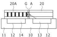
- the module device 10 comprises a flat rectangular housing 11, with a pair of mounting holes 12 drilled at intervals in the longitudinal direction of the surface of the housing 11, with a light source 13 fitted into one of the pair of mounting holes 12, which lights up and emits a light beam as shown by the arrow in FIG. 8.
- a light sensor 14 is fitted into the other mounting hole 12, and this light sensor 14 detects the light beam that has passed from the light source 13 through the pair of light transmission direction control sheets 20 and 20A.
- the pair of light transmission direction control sheets 20 and 20A includes a light transmission direction control sheet 20 installed on the surface of the housing 11 facing the light source 13, and a light transmission direction control sheet 20A installed on the surface of the housing 11 facing the light sensor 14, each formed as a flat rectangular sheet, and functions to transmit the light irradiated from the light source 13 to the light sensor 14.
- the pair of light transmission direction control sheets 20 and 20A are arranged in a horizontal row and are adjacent to each other, with the adjacent peripheral surfaces facing each other with a gap G.
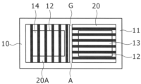
- the light transmission direction control sheet 20A facing the light sensor 14 is rotated 90° from the viewpoint of directivity and faces in a different direction from the light transmission direction control sheet 20 facing the light source 13, as shown in FIG. 9.
- a pair of conventional light transmission direction control sheets 20, 20A are constructed as described above, with adjacent peripheral surfaces facing each other with a gap G between them, which creates an air layer A that diffuses light rays, resulting in a problem of the optical sensor 14 malfunctioning or making an erroneous detection.
- a method has been proposed in which a silicone-based or acrylic-based filling adhesive 21 is injected into the gap G between the peripheral surfaces of the pair of light transmission direction control sheets 20, 20A to fill the air layer A, as shown in Figure 10.
- the present invention has been made in consideration of the above, and aims to provide a light transmission direction control sheet and a manufacturing method thereof that can eliminate air gaps without injecting adhesive into the gaps.
- the present invention is characterized by including opposing first and second light-transmitting resin films and a plurality of louver layers interposed between the first and second light-transmitting resin films and bonded with an adhesive, and by butting the plurality of louver layers together to bring them into close contact.
- Each louver layer is formed by alternating multiple light-transmitting bands and light-shielding bands, with each light-transmitting band being made of light-transmitting silicone rubber and each light-shielding band being made of colored silicone rubber, and it is preferable that the hardness of these silicone rubbers is 73 or more and 83 or less when measured with a type A durometer in accordance with JIS K6253.
- the silicone rubber of each louver layer has a tensile strength of 7.5 MPa or more and 13.5 MPa or less when measured in accordance with JIS K6251, an elongation at break of 270% or more and 490% or less when measured in accordance with JIS K6251, and a tear strength of 8 kN/m or more and 28 kN/m or less when measured in accordance with JIS K6252.
- the adhesive is preferably an adhesive silicone rubber, and the hardness after curing is preferably 10 or more and 60 or less when measured with a type A durometer in accordance with JIS K6253. It can also be attached to a modular device and cover the light source and light sensor of the modular device.
- the arrangement direction in which the light transmission bands and shading bands of the louver layer facing the light source are arranged can be made approximately perpendicular to the arrangement direction of the multiple louver layers, and the arrangement direction in which the light transmission bands and shading bands of the louver layer facing the light sensor can be made approximately coincident with the arrangement direction of the multiple louver layers.
- the present invention provides a method for producing a light transmission direction control sheet according to claim 1 or 2,
- a plurality of elastic louver layers are bonded to a first light-transmitting resin film with an adhesive, the plurality of louver layers are butted together to bring them into close contact, a second light-transmitting resin film is bonded to the plurality of louver layers with an adhesive, and the adhesive is heated and cured.
- recesses can be formed on the butt periphery of some of the louver layers, and protrusions can be formed on the butt periphery of the remaining louver layers, and the multiple louver layers can be butted together by fitting these recesses and protrusions together.
- the multiple louver layers in the claims may be formed to the same size from a specified resin or elastomer, or may be formed to different sizes.
- the number of louver layers is not particularly limited, and may be 2, 3, 4, 5, 6, etc. Some of the multiple louver layers may be crossed by changing their orientation.
- the physical properties of the silicone rubber of the louver layers include approximate values as long as there is no difference in the action and effect.
- the concave and convex portions may each be singular, but they can also be formed in multiples.
- the up-down, front-back, left-right directions of the light transmission direction control sheet according to the present invention are directions based on the drawings, and can be appropriately changed as necessary.
- multiple louver layers are not arranged with gaps between them, but are butted up against each other and placed in close contact, eliminating gaps between the multiple louver layers and eliminating the air gap between the multiple louver layers.
- louver layers are butted together to form a tight seal with no gaps, which has the effect of eliminating air gaps without filling the gaps with adhesive.
- the louver layer is formed from silicone rubber so that it can be elastically deformed, and this not only improves adhesion but also improves the heat resistance, cold resistance, moisture resistance, environmental resistance, flexibility, colorability, transparency, etc., of the louver layer.
- the hardness of the silicone rubber forming the louver layer is 73 or more and 83 or less when measured with a type A durometer in accordance with JIS K6253, so warping and deformation of the louver layer can be prevented, and by preventing this warping and deformation, it is possible to prevent the formation of air layers between multiple louver layers.
- the adhesive is adhesive silicone rubber, so that the adhesion between the louver layer and the silicone rubber can be improved.
- the hardness of the adhesive after curing is 10 to 60 when measured with a type A durometer in accordance with JIS K6253, so that warping and deformation of the louver layer can be prevented, and it is also possible to prevent air spaces from forming between multiple louver layers.
- the use of a light transmission direction control sheet makes it possible to appropriately transmit light emitted from a light source to an optical sensor.
- multiple louver layers are bonded to a first light-transmitting resin film, and these multiple louver layers can be butted together while being manually adjusted over a period of time, which reduces the occurrence of gaps between the multiple louver layers.
- the multiple louver layers are positioned by fitting the recesses and protrusions together, and misalignment of the louver layers is regulated, making it possible to prevent the louver layers from misaligning and generating air bubbles due to differences in the thermal expansion coefficients of the first and second light-transmitting resin films and the louver layers.
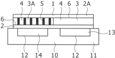
- FIG. 2 is an explanatory diagram showing a state in which a light transmission direction control sheet is installed and used in a module device according to an embodiment of the light transmission direction control sheet of the present invention.
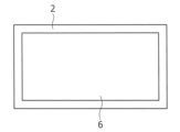
- 1 is a plan view illustrating a state in which a light transmission direction control sheet is installed and used in a module device according to an embodiment of the light transmission direction control sheet of the present invention.
- FIG. FIG. 2 is a plan view illustrating a state in which adhesive silicone rubber is applied to a first light-transmitting resin film in an embodiment of a method for producing a light transmission direction control sheet according to the present invention.
- FIG. 1 is a plan view illustrating a state in which a light transmission direction control sheet is installed and used in a module device according to an embodiment of the light transmission direction control sheet of the present invention.
- FIG. FIG. 2 is a plan view illustrating a state in which adhesive silicone rubber is applied to a first light-transmitting resin film in an embodiment of a method for producing a light transmission direction control sheet according to the
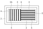
- FIG. 2 is a plan view illustrating a state in which a pair of louver layers are laminated and adhered to an adhesive silicone rubber applied to a first light-transmitting resin film in an embodiment of a method for producing a light transmission direction control sheet according to the present invention.
- FIG. 11 is a plan view illustrating a state in which a second light-transmitting resin film is laminated and bonded to a pair of louver layers in an embodiment of a method for producing a light transmission direction control sheet according to the present invention.
- FIG. 2 is a plan view illustrating a state in which excess portions of the first and second light-transmitting resin films have been removed along the peripheral edges of a pair of louver layers in an embodiment of a method for manufacturing a light transmission direction control sheet according to the present invention.
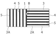
- FIG. 11 is a plan view illustrating a manufacturing method of a light transmission direction control sheet according to a second embodiment of the present invention.
- 1 is an explanatory diagram showing a state in which a pair of light transmission direction control sheets are installed in a module device and used;
- FIG. 13 is a plan view illustrating a state in which a pair of light transmission direction control sheets are installed and used in a module device.
- 10 is an explanatory diagram showing a method of filling an air layer by injecting a filling adhesive into a gap between peripheral surfaces of a pair of light transmission direction control sheets.
- FIG. 1 is an explanatory diagram showing a state in which a pair of light transmission direction control sheets are installed in a module device and used
- FIG. 13 is a plan view illustrating a state in which a pair of light transmission direction control sheets are installed and used in a module device.
- 10 is an explanatory diagram showing a method of filling an air layer by injecting a filling adhesive into a gap between peripheral surfaces of
- the light transmission direction control sheet 1 in this embodiment has a multi-layer structure including first and second light-transmitting resin films 2, 2A facing each other and a pair of louver layers 3, 3A interposed between the first and second light-transmitting resin films 2, 2A and bonded with an adhesive 6, and is used in a module device 10 as a control sheet for controlling the optical path of light rays.
- the pair of louver layers 3, 3A are formed from a specified elastic elastomer and brought into close contact with each other, thereby contributing to the achievement of Goal 9 of the SDGs (the United Nations' international goals for sustainable development, consisting of 17 global goals and 169 targets (achievement criteria)) adopted at the United Nations Summit.
- the light transmission direction control sheet 1 is formed into a rectangular shape, such as a flat rectangle or a square, and is placed on the surface of the module device 10 to cover the light source 13 for emitting light and the light sensor 14 for receiving light of the module device 10. At least a portion of the periphery of this light transmission direction control sheet 1 may be curved, or at least one of the four corners may be chamfered.
- the module device 10 has a housing 11 that is rectangular in plan view and is approximately rectangular.
- a pair of mounting holes 12 are drilled in a horizontal row at intervals along the longitudinal direction of the surface of the housing 11.
- a light source 13 such as an LED is fitted into one of the pair of mounting holes 12, and this light source 13 lights up and irradiates a beam of light.
- a light sensor 14 is fitted into the other mounting hole 12, and this light sensor 14 detects the beam of light that has passed from the light source 13 through the light transmission direction control sheet 1.
- the first and second light-transmitting resin films 2 and 2A are made of polycarbonate resin films that are excellent in heat resistance of 90°C or more, weather resistance, impact resistance, dimensional accuracy, transparency, and are resistant to warping and deformation, and are formed to a size larger than the pair of closely-contacted louver layers 3 and 3A before the light transmission direction control sheet 1 is manufactured, and function to sandwich the pair of louver layers 3 and 3A and prevent air from entering.
- the thickness of the first and second light-transmitting resin films 2 and 2A is set to 0.1 mm or more and 0.3 mm or less, preferably 0.189 mm or more and 0.2 mm or less, more preferably 0.195 mm or more and 0.2 mm or less, and even more preferably around 0.2 mm, from the viewpoint of reducing the installation space and ensuring rigidity to prevent warping.
- the light transmittance when light is incident only on the first and second light-transmitting resin films 2 and 2A is preferably 75% or more, more preferably 75% to 100%, and even more preferably 85% to 100% in order to obtain excellent transparency.
- the polycarbonate resin film used for the first and second light-transmitting resin films 2 and 2A preferably has a flexural modulus of elasticity of 91 MPa or more and 2300 MPa or less when measured in accordance with the measurement test method of ISO 178.
- the pair of louver layers 3, 3A are arranged horizontally, with the louver layer 3 facing the light source 13 of the module device 10 from above and the louver layer 3A facing the light sensor 14 of the module device 10 from above, with the opposing surfaces butted together to form close contact with no gaps, transmitting the light irradiated from the light source 13 to the light sensor 14 and functioning to eliminate the conventional air layer A.
- the louver layer 3A facing the light sensor 14 is rotated 90 degrees and oriented in a direction perpendicular to the direction of the louver layer 3 facing the light source 13, from the perspective of guiding the light to the light sensor 14.
- Each louver layer 3, 3A is formed into a planar rectangle of 15 inches or the like by repeatedly arranging a plurality of light transmitting bands 4 and light blocking bands 5 in a horizontal row.
- the thickness of each louver layer 3, 3A is 100 ⁇ m to 5000 ⁇ m, preferably 500 ⁇ m to 3500 ⁇ m, more preferably 600 ⁇ m to 2000 ⁇ m, and even more preferably about 1200 ⁇ m, from the viewpoint of adjusting the directivity of the light passing through the light transmission direction control sheet 1 in any direction and facilitating manufacturing.
- the thickness of the louver layer 3, 3A is made constant, but the constant here includes a range of ⁇ 5% of the design value in the thickness direction.
- the thickness of this louver layer 3, 3A can be measured from a cross-sectional photograph of the louver layer 3, 3A alone, and the average value of the values obtained by measuring at 10 or more points is preferably used.
- the louver layers 3 and 3A have each light-transmitting band 4 formed in a band shape from light-transmitting silicone rubber that has excellent heat resistance of 90°C or more, cold resistance, moisture resistance, environmental resistance, flexibility, colorability, transparency, etc., and helps prevent warping and deformation, and each light-shielding band 5 is formed in a band shape from silicone rubber that is transparent silicone rubber colored with a light-shielding property, and these light-transmitting bands 4 and light-shielding bands 5 are formed at the same height, making the front and back symmetrical.
- silicone rubber examples include a silicone rubber composition generally called millable rubber, which is made of a diorganopolysiloxane whose molecular chain ends are blocked with hydroxysilyl or vinylsilyl groups and an organic peroxide; and an addition reaction type organosilicone rubber composition, which is made by compounding a diorganopolysiloxane having at least two vinyl groups bonded to silicon atoms in the molecule with an organohydrogenpolysiloxane having at least three hydrogen atoms bonded to silicon atoms (i.e., SiH bonds) in the molecule and a platinum catalyst.
- Specific examples of silicone rubber include KE-153U (product name, manufactured by Shin-Etsu Chemical Co., Ltd.).
- the silicone rubber has a density of 1.21 g/ cm3 or more and 1.25 g/ cm3 or less, preferably around 1.24 g/ cm3 , as measured at 23°C in accordance with JIS K6268.
- the hardness is optimally 73 or more and 83 or less, preferably 78 or more and 79 or less, as measured with a rubber/plastic hardness tester (type A durometer) in accordance with JIS K6253.
- the tensile strength is optimally 7.5 MPa or more and 13.5 MPa or less, preferably around 10.5 MPa, as measured in accordance with JIS K6251.
- the elongation at break of silicone rubber should be 270% or more and 490% or less, preferably 310% or more and 380% or less.
- the tear strength (crescent shape) should be 8 kN/m or more and 28 kN/m or less, preferably 13 kN/m or more and 18 kN/m or less, measured according to JIS K6252. These measurements can be made using measuring equipment and testing machines from M&K Corporation, ITS Japan Co., Ltd., etc.
- Each light transmission band 4 is formed of transparent silicone rubber with a vertically long rectangular cross section, and functions to transmit light. From the viewpoint of controlling the directivity of light rays in any direction and facilitating manufacturing, the average width of this light transmission band 4 is preferably between 50 ⁇ m and 200 ⁇ m, more preferably between 80 ⁇ m and 170 ⁇ m, and even more preferably between 100 ⁇ m and 150 ⁇ m, taking into account tolerances. In addition, from the viewpoint of obtaining excellent transparency, the light transmittance when light rays are incident only on the light transmission band 4 is 75% or more, preferably between 75% and 100%, and even more preferably between 85% and 100%.
- Each light-shielding band 5 is made of silicone rubber that has been colored to block light, and is formed into a rectangular shape with a vertically elongated cross section that is thinner and narrower than the light-transmitting band 4, and functions to block light rays.
- the silicone rubber has the above physical properties and is colored with light-shielding properties by adding a colorant such as a pigment or dye to the type of silicone rubber used for the light-transmitting band 4.
- colorants include common organic or inorganic pigments such as carbon black, iron oxide, titanium oxide, yellow iron oxide, disazo yellow, and phthalocyanine blue, with black carbon black being the most suitable, as it has excellent blocking properties.
- each light blocking band 5 should be 1 ⁇ m or more and 50 ⁇ m or less, preferably 5 ⁇ m or more and 30 ⁇ m or less, more preferably 8 ⁇ m or more and 20 ⁇ m or less, and even more preferably around 10 ⁇ m, taking into account tolerances.
- the adhesive 6 is made of transparent silicone rubber that has adhesive properties in consideration of its compatibility with silicone rubber, and it bonds the opposing surfaces of the first and second light-transmitting resin films 2, 2A and the pair of louver layers 3, 3A to transmit light.
- Transparent silicone rubber includes silicone-based adhesives and adhesive silicone rubber sheets that have excellent heat resistance of 90°C or more, cold resistance, moisture resistance, environmental resistance, flexibility, transparency, etc., and help prevent warping and deformation.
- Specific examples of silicone-based adhesives include KE-1825 (product name manufactured by Shin-Etsu Chemical Co., Ltd.) and KE-1056 (product name manufactured by Shin-Etsu Chemical Co., Ltd.), which are thermosetting adhesives.
- the adhesive 6 hardens to become an adhesive layer, and from the viewpoint of making the light transmission direction control sheet 1 thinner, the optimum thickness of this adhesive layer is 10 ⁇ m to 32 ⁇ m, preferably 15 ⁇ m to 25 ⁇ m, and more preferably about 20 ⁇ m. Furthermore, the hardness of the adhesive layer after the adhesive 6 hardens, when measured with a type A durometer in accordance with JIS K6253, is optimally 10 to 60, preferably 10 to 30 or 30 to 60, and more preferably 10 to 30 or 50 to 60. This is because if the hardness of the adhesive layer is 10 to 60, it is possible to prevent warping and deformation of the pair of louver layers 3 and 3A.
- the light transmittance is preferably 65% or more, more preferably 65% to 100%, and even more preferably 80% to 100%, in order to obtain excellent transparency.
- a pair of louver layers 3 and 3A are manufactured. Specifically, a plurality of transparent silicone rubber sheets for the light transmission band and a plurality of silicone rubber sheets for the light shielding band colored black are prepared, and these plurality of silicone rubber sheets for the light transmission band and the silicone rubber sheets for the light shielding band are alternately laminated to form a laminate, and this laminate is heated, vulcanized, and pressurized to form a block body, and then the block body is cut, whereby a pair of elastic louver layers 3 and 3A can be manufactured into sheets.
- the silicone rubber sheets for light-transmitting bands and the silicone rubber sheets for light-shielding bands can be manufactured by extrusion molding, calendar molding, or press molding.
- the silicone rubber sheets for light-transmitting bands and the silicone rubber sheets for light-shielding bands can be bonded by heat pressing, but it is best to alternately laminate and bond them with a silicone-based transparent adhesive, which is expected to provide reliable adhesion.
- a first light-transmitting resin film 2 is prepared, and a thin layer of transparent adhesive silicone rubber that will serve as adhesive 6 is applied to most of the surface area of this first light-transmitting resin film 2, excluding the peripheral areas (see FIG. 3).
- the pair of louver layers 3, 3A are butted together so that they face in different directions and are brought into close contact, and the pair of louver layers 3, 3A are laminated and bonded to the surface of the first light-transmitting resin film 2 using the adhesive silicone rubber, and the pair of louver layers 3, 3A are butted together again by hand and adjusted so that they are tightly attached without any gaps (see FIG. 4).
- the arrangement direction of the light transmitting bands 4 and light blocking bands 5 of the louver layer 3 facing the light source 13 is different from and perpendicular to the arrangement direction of the pair of louver layers 3, 3A (left and right direction in FIG. 4).
- the arrangement direction of the light transmitting bands 4 and light blocking bands 5 of the louver layer 3A facing the light sensor 14 matches the arrangement direction of the pair of louver layers 3, 3A.
- a second light-transmitting resin film 2A is prepared, and a thin layer of transparent adhesive silicone rubber, which will serve as adhesive 6, is applied to most of the surface area of this second light-transmitting resin film 2A except for the peripheral areas, and this adhesive silicone rubber is then adhered to the surfaces of the pair of louver layers 3, 3A (see FIG. 5).
- a rotatable hand roll is pressed against the second light-transmitting resin film 2A, and the hand roll is rotated and shifted while adhering, which allows air to be expelled to the outside from between the pair of louver layers 3, 3A and the second light-transmitting resin film 2A, preventing diffuse reflection of light rays and reduced transparency due to remaining air.
- the pair of louver layers 3, 3A are sandwiched between the first and second light-transmitting resin films 2, 2A in this manner, they are heated and cured to form the adhesive 6 into an adhesive layer, and then the excess portions of the first and second light-transmitting resin films 2, 2A are cut and removed along the periphery of the pair of louver layers 3, 3A (see Figure 6), thereby producing the light transmission direction control sheet 1.
- the refractive index of the first and second light-transmitting resin films 2 and 2A in the manufactured light transmission direction control sheet 1 is 1.57 or more and 1.59 or less, for example, around 1.58, when the first and second light-transmitting resin films 2 and 2A are polycarbonate resin films. These refractive indices can be measured with a refractometer in accordance with JIS K7142, as described above. Furthermore, the refractive index of the light-transmitting bands 4 of the louver layers 3 and 3A is preferably 1.41 or more and 1.43 or less, and preferably around 1.42, in order to prevent interfacial reflection.
- the refractive index of the adhesive layer in which the adhesive 6 has hardened is preferably 1.40 or more and 1.42 or less, and preferably around 1.41, in order to prevent interfacial reflection.
- the pair of louver layers 3, 3A are butted together in close contact and the air layer A between the pair of louver layers 3, 3A is eliminated, thereby preventing diffuse reflection of light rays.
- elastic louver layers 3, 3A made of silicone rubber are butted together, rather than hard louver layers 3, 3A, the butted surfaces of the louver layers 3, 3A elastically deform to reliably fill the gap G. Therefore, the optical sensor 14 does not malfunction or detect incorrectly.
- the average width of the light transmission zone 4 is 100 ⁇ m or more and 150 ⁇ m or less, stacking and cutting operations can be facilitated.
- Figure 7 shows a second embodiment of the present invention, in which a plurality of dovetail grooves 7 that serve as recesses are cut out and formed at predetermined intervals on the butting surface of one of a pair of louver layers 3, 3A, and a plurality of dovetail necks 8 that serve as protrusions are formed and formed at predetermined intervals on the butting surface of the other louver layer 3A, and the pair of louver layers 3, 3A are butted together while these multiple dovetail grooves 7 and dovetail necks 8 are fitted together.
- the dovetail grooves 7 and dovetail necks 8 of the pair of louver layers 3 and 3A are formed in plurality by, for example, a punching blade when cutting the block body.
- the process when manufacturing the light transmission direction control sheet 1, the process is the same up to the point where adhesive silicone rubber is applied to the surface of the first light-transmitting resin film 2, but the orientation of the pair of louver layers 3, 3A is changed, and the dovetail grooves 7 and dovetail necks 8 of the pair of louver layers 3, 3A are butted together while closely fitting them together, and the pair of louver layers 3, 3A are laminated and bonded to the surface of the first light-transmitting resin film 2 via the adhesive silicone rubber.
- the arrangement direction of the light transmitting bands 4 and light blocking bands 5 of the louver layer 3 facing the light source 13 is perpendicular to the arrangement direction of the pair of louver layers 3, 3A.
- the arrangement direction of the light transmitting bands 4 and light blocking bands 5 of the louver layer 3A facing the light sensor 14 coincides with the arrangement direction of the pair of louver layers 3, 3A (the left-right direction in FIG. 7).
- a second light-transmitting resin film 2A is prepared, and a thin layer of transparent adhesive silicone rubber, which will serve as adhesive 6, is applied to most of the surface area of this second light-transmitting resin film 2A excluding the peripheral areas, and this adhesive silicone rubber is then adhered to the surfaces of the pair of louver layers 3, 3A.
- a rotatable hand roll is pressed against the second light-transmitting resin film 2A, and the hand roll is rotated and shifted while adhering, which allows air to be expelled to the outside from between the pair of louver layers 3, 3A and the second light-transmitting resin film 2A, preventing diffuse reflection of light rays and reduced transparency due to remaining air.
- each adhesive 6 is heated and cured to form an adhesive layer, a product forming line 9 for cutting is drawn on the second light-transmitting resin film 2A, and then the first light-transmitting resin film 2, the pair of louver layers 3, 3A, and the second light-transmitting resin film 2A are cut and removed along the product forming line 9 of the second light-transmitting resin film 2A, thereby manufacturing the light transmission direction control sheet 1. As shown in FIG.
- the product forming line 9 is drawn with a required number of dotted lines or the like in an area of the pair of louver layers 3, 3A that does not include the multiple dovetail grooves 7 and dovetail necks 8.
- the other parts are the same as those in the above embodiment, so a description thereof will be omitted.
- the first and second light-transmitting resin films 2 and 2A are polycarbonate resin films, but this is not limited to this.
- polybutylene terephthalate resin films or acrylic resin films may be used.
- at least one of the first and second light-transmitting resin films 2 and 2A may be treated with an anti-glare (AG) coating to prevent light from being reflected and becoming dazzling, or a hard coating.
- AG anti-glare
- a protective acrylic plate may be laminated to at least one of the first and second light-transmitting resin films 2 and 2A. Furthermore, the arrangement direction of the light-transmitting bands 4 and light-shielding bands 5 of the louver layer 3A facing the light sensor 14 may be approximately perpendicular to the arrangement direction of the pair of louver layers 3 and 3A. Furthermore, the dovetail grooves 7 and dovetail necks 8 can be modified to have similar shapes as necessary.
- Example 1 In order to manufacture the light transmission direction control sheet shown in Fig. 1 and Fig. 2, a plurality of transparent silicone rubber sheets for light transmission bands and silicone rubber sheets for light shielding bands colored black were prepared, and these silicone rubber sheets for light transmission bands and silicone rubber sheets for light shielding bands were alternately laminated and heat-pressed to form a laminate.
- Each silicone rubber sheet for light transmission bands was KE1571U (manufactured by Shin-Etsu Chemical Co., Ltd.: product name) with a thickness of 125 ⁇ m.
- a silicone rubber sheet for light shielding bands was KE153U (manufactured by Shin-Etsu Chemical Co., Ltd.: product name) with a thickness of 10 ⁇ m, in which 100 parts by mass of silicone rubber was mixed with 15 parts by mass of carbon black, was used.
- the durometer hardness, tensile strength, elongation at break, and tear strength (crescent shape) of the type A silicone rubber sheet for the light transmission band used in the laminate were measured.
- the hardness of the test piece of the silicone rubber sheet measured in accordance with JIS K6253-3 was 78
- the tensile strength of the silicone rubber sheet measured in accordance with JIS K6251 was 10.5 MPa
- the elongation at break of the silicone rubber sheet measured in accordance with JIS K6251 was 380%
- the tear strength of the silicone rubber sheet measured in accordance with JIS K6252 was 18 kN/m.
- the hardness of the test piece was measured with an Asker Rubber Hardness Tester Type A (product name, manufactured by Kobunshi Keiki Co., Ltd.).
- the laminate was constructed, it was heated, vulcanized, and pressurized to form a block, which was then cut to form a pair of louver layers with a thickness of 1.2 mm into a sheet shape. When cutting the block, the cut was made perpendicular to the surface of the sheet.
- the first light-transmitting resin film was prepared, and a thin layer of transparent adhesive silicone rubber was applied to most of the surface of the first light-transmitting resin film, excluding the periphery.
- the first light-transmitting resin film was a commercially available polycarbonate resin film with a thickness of 0.2 mm.
- KE1825 product name, manufactured by Shin-Etsu Chemical Co., Ltd. was used as the transparent adhesive silicone rubber.
- a second light-transmitting resin film was prepared, and a thin layer of transparent adhesive silicone rubber was applied to most of the surface area of this second light-transmitting resin film, excluding the peripheral areas, and this adhesive silicone rubber was adhered to the surface of a pair of louver layers.
- the second light-transmitting resin film was a commercially available polycarbonate resin film with a thickness of 0.2 mm.
- the transparent adhesive silicone rubber was KE1825 (product name, manufactured by Shin-Etsu Chemical Co., Ltd.).
- the hand roll was pressed against the second light-transmitting resin film and the hand roll was rotated and shifted while adhering, allowing air to be expelled to the outside from between the pair of louver layers and the second light-transmitting resin film.
- first and second light-transmitting resin films After sandwiching the pair of louver layers between the first and second light-transmitting resin films in this way, they are heated and cured to form hardened adhesive layers of each adhesive, and then the excess portions of the first and second light-transmitting resin films are cut and removed along the periphery of the pair of louver layers to produce a light transmission direction control sheet.
- each adhesive layer of the manufactured light transmission direction control sheet was measured to be 20 ⁇ m.
- the hardness of this adhesive layer was measured on a test piece with a type A durometer in accordance with JIS K 6253-3 to be 30.
- the measuring device used was an Asker Rubber Hardness Tester Type A (manufactured by Kobunshi Keiki Co., Ltd.: product name).
- the refractive index of each adhesive layer was measured to be 1.41, and the refractive index of the first and second light-transmitting resin films was measured to be 1.58. These refractive indices were measured with a refractometer in accordance with JIS K7142.
- the refractometer used was a multi-wavelength Abbe refractometer DR-M2 (manufactured by Atago Co., Ltd.: product name) with a measurement wavelength of 589 nm.
- Example 2 When cutting the block body of Example 1 to form a pair of louver layers with a thickness of 1.2 mm into sheets, two dovetail grooves that would become recesses were cut out at a specified interval on the butting surface of one of the louver layers, and two dovetail necks that would become protrusions were punched out at a specified interval on the butting surface of the other louver layer. After the pair of louver layers was formed into sheets in this way, the orientations of the pair of louver layers were shifted by 90°, and the dovetail grooves and dovetail necks of the pair of louver layers were butted together while tightly fitting them together.
- Example 1 a thin layer of transparent adhesive silicone rubber was applied to most of the surface area of the first light-transmitting resin film, and a pair of closely spaced louver layers were laminated and bonded to the surface of this first light-transmitting resin film via the adhesive silicone rubber.
- the first light-transmitting resin film and adhesive silicone rubber were the same as in Example 1.
- the hand roll of Example 1 was pressed against the pair of louver layers, and air was expelled to the outside from between the first light-transmitting resin film and the pair of louver layers.
- Example 2 a second light-transmitting resin film was prepared, and a thin layer of transparent adhesive silicone rubber was applied to most of the surface area of this second light-transmitting resin film, and this adhesive silicone rubber was adhered to the surface of the pair of louver layers.
- the second light-transmitting resin film and adhesive silicone rubber were the same as in Example 1.
- the hand roll of Example 1 was pressed against the second light-transmitting resin film, and air was exhausted to the outside from between the pair of louver layers and the second light-transmitting resin film.
- first and second light-transmitting resin films After sandwiching the pair of louver layers between the first and second light-transmitting resin films in this way, they are heated and cured to turn the adhesive into an adhesive layer, and a product formation line for cutting as shown in Figure 7 is drawn on the surface of the second light-transmitting resin film.
- the first light-transmitting resin film, the pair of louver layers, and the second light-transmitting resin film are then cut and removed along the product formation line to produce a light transmission direction control sheet.
- each adhesive layer of the manufactured light transmission direction control sheet was measured, and the values were the same as those in Example 1.
- the refractive indexes of the first and second light-transmitting resin films were also measured, and were the same as those in Example 1.
- the light transmission direction control sheet and its manufacturing method according to the present invention are used in the manufacturing fields of various detection devices, image display devices, medical devices such as infusion devices, liquid crystal displays, CIDs, etc.
Landscapes
- Physics & Mathematics (AREA)
- General Physics & Mathematics (AREA)
- Engineering & Computer Science (AREA)
- Optics & Photonics (AREA)
- Computer Networks & Wireless Communication (AREA)
- Radar, Positioning & Navigation (AREA)
- Remote Sensing (AREA)
- Optical Elements Other Than Lenses (AREA)
Abstract
隙間に接着剤を注入しなくても空気層を排除することができる光透過方向制御シート及びその製造方法を提供する。 相対向する第一、第二の光透過性樹脂フィルム2・2Aと、この第一、第二の光透過性樹脂フィルム2・2Aの間に介在して接着剤6で接着される一対のルーバー層3・3Aとを備え、モジュール装置10に使用されて光線の光路を制御する光透過方向制御シート1であり、一対のルーバー層3・3Aを突き合わせて隙間なく密接させる。一対のルーバー層3・3Aの間の空気層を排除するので、光線の乱反射を防止することができる。したがって、モジュール装置10の光センサ14が誤作動したり、誤検知することがない。また、隙間に充填接着剤を注入して空気層を埋める必要がないので、空気層の一部が残存したり、充填接着剤による光透過方向制御シート1の汚染を招くおそれを払拭できる。
Description
本発明は、各種の検出装置や自動車の画像表示装置等に使用されて光路や可視角度を制御する光透過方向制御シート及びその製造方法に関するものである。
従来、モジュール装置10に光透過方向制御シート20・20Aを使用する場合には図8や図9に示すように、モジュール装置10の発光用の光源13と受光用の光センサ14とに、光透過方向制御シート20・20Aをそれぞれ対向させ、この一対の光透過方向制御シート20・20Aにより、光線の光路を制御するようにしている(特許文献1参照)。
モジュール装置10は、平面矩形のハウジング11を備え、このハウジング11の表面長手方向に一対の取付穴12が間隔をおいて穿孔され、この一対の取付穴12のうち、一方の取付穴12に光源13が嵌着されており、この光源13が点灯して図8に矢印で示す光線を照射する。これに対し、他方の取付穴12には光センサ14が嵌着され、この光センサ14が光源13から一対の光透過方向制御シート20・20Aを通過して来た光線を検知する。
一対の光透過方向制御シート20・20Aは、ハウジング11の表面に設置されて光源13に対向する光透過方向制御シート20と、ハウジング11の表面に設置されて光センサ14に対向する光透過方向制御シート20Aとを備え、平面矩形のシートにそれぞれ形成されており、光源13から照射された光線を光センサ14に伝送するよう機能する。この一対の光透過方向制御シート20・20Aは、横一列に配列されて相互に近接し、近接する周面同士が隙間Gをおいて対向する。一対の光透過方向制御シート20・20Aのうち、光センサ14に対向する光透過方向制御シート20Aは、図9に示すように、指向性の観点から、90°回転して光源13に対向する光透過方向制御シート20の向きとは異なる方向に向けられている。
従来における一対の光透過方向制御シート20・20Aは、以上のように構成され、近接する周面同士が隙間Gをおいて対向するので、隙間Gが空気層Aを形成して光線を乱反射させ、その結果、光センサ14が誤作動したり、誤検知するという問題が生じる。この問題を解消する手段として、図10に示すように、一対の光透過方向制御シート20・20Aの周面間の隙間Gにシリコーン系やアクリル系の充填接着剤21を注入して空気層Aを埋める方法が提案されている。
しかしながら、一対の光透過方向制御シート20・20Aを設置した後にこれらの隙間Gに充填接着剤21を適切に注入して空気層Aを完全に埋めるのは、実際問題として容易なことではない。例えば、充填接着剤21の注入量が不足する場合には、空気層Aの一部が残存するし、充填接着剤21の注入量が過剰な場合には、光透過方向制御シート20・20Aの対向する周面付近の汚染を招くおそれがある。
本発明は上記に鑑みなされたもので、隙間に接着剤を注入しなくても空気層を排除することができる光透過方向制御シート及びその製造方法を提供することを目的としている。
本発明においては上記課題を解決するため、対向する第一、第二の光透過性樹脂フィルムと、この第一、第二の光透過性樹脂フィルムの間に介在して接着剤で接着される複数のルーバー層とを含み、この複数のルーバー層を突き合わせて密接させることを特徴としている。
なお、各ルーバー層は、複数の光透過帯と遮光帯とが交互に並ぶことにより形成され、各光透過帯が光透過性のシリコーンゴムにより形成されるとともに、各遮光帯が着色されたシリコーンゴムにより形成されており、これらのシリコーンゴムの硬さがJIS K6253に準拠してタイプAのデュロメータにより測定された場合に73以上83以下であることが好ましい。
また、各ルーバー層のシリコーンゴムは、JIS K6251に準拠して測定された場合の引張り強さが7.5MPa以上13.5MPa以下、JIS K6251に準拠して測定された場合の切断時伸びが270%以上490%以下、JIS K6252に準拠して測定された場合の引き裂き強さが8kN/m以上28kN/m以下であることが好ましい。
また、接着剤は、接着性シリコーンゴムであり、硬化後の硬さがJIS K6253に準拠してタイプAのデュロメータにより測定された場合に10以上60以下であることが好ましい。
また、モジュール装置に取り付けられ、このモジュール装置の光源と光センサとを被覆することができる。
また、光源に対向するルーバー層の光透過帯と遮光帯とが配列される配列方向を、複数のルーバー層の配列方向と略直交させ、光センサに対向するルーバー層の光透過帯と遮光帯とが配列される配列方向を、複数のルーバー層の配列方向と略一致させることができる。
また、モジュール装置に取り付けられ、このモジュール装置の光源と光センサとを被覆することができる。
また、光源に対向するルーバー層の光透過帯と遮光帯とが配列される配列方向を、複数のルーバー層の配列方向と略直交させ、光センサに対向するルーバー層の光透過帯と遮光帯とが配列される配列方向を、複数のルーバー層の配列方向と略一致させることができる。
また、本発明においては上記課題を解決するため、請求項1又は2に記載した光透過方向制御シートの製造方法であって、
第一の光透過性樹脂フィルムに、光透過帯と遮光帯とが交互に並ぶ弾性のルーバー層を接着剤により複数接着するとともに、この複数のルーバー層を突き合わせて密接させ、複数のルーバー層に第二の光透過性樹脂フィルムを接着剤により接着し、接着剤を加熱硬化させることを特徴としている。
第一の光透過性樹脂フィルムに、光透過帯と遮光帯とが交互に並ぶ弾性のルーバー層を接着剤により複数接着するとともに、この複数のルーバー層を突き合わせて密接させ、複数のルーバー層に第二の光透過性樹脂フィルムを接着剤により接着し、接着剤を加熱硬化させることを特徴としている。
なお、複数のルーバー層のうち、一部のルーバー層の突き合わせ周縁部に凹部を形成し、残部のルーバー層の突き合わせ周縁部には凸部を形成し、これら凹部と凸部とを嵌め合わせながら複数のルーバー層を突き合わせることができる。
ここで、特許請求の範囲における複数のルーバー層は、所定の樹脂やエラストマーにより同じ大きさに形成されても良いし、異なる大きさに形成されても良い。このルーバー層の数は、特に限定されるものではなく、2個、3個、4個、5個、6個等とすることができる。複数のルーバー層のうち、一部のルーバー層は、向きを変えて交差させることができる。ルーバー層のシリコーンゴムの物性値は、作用効果に相違がないのであれば、近似値が含まれる。また、凹部と凸部は、それぞれ単数でも良いが、それぞれ複数形成することもできる。さらに、本発明に係る光透過方向制御シートの上下前後左右方向は、図面を基準にした方向であり、必要に応じ、適宜変更することができる。
本発明によれば、複数のルーバー層を隙間を介して配列するのではなく、突き合わせて密接させるので、複数のルーバー層の間に隙間がなくなり、複数のルーバー層の間の空気層を排除することができる。
本発明によれば、複数のルーバー層を突き合わせて隙間なく密接させるので、隙間に接着剤を充填しなくても空気層を排除することができるという効果がある。
請求項2記載の発明によれば、ルーバー層がシリコーンゴムにより弾性変形可能に形成されるので、密着力を向上させることができる他、ルーバー層の耐熱性、耐寒性、耐湿性、耐環境特性、柔軟性、着色性、透明性等を向上させることができる。また、ルーバー層を形成するシリコーンゴムの硬さがJIS K6253に準拠してタイプAのデュロメータにより測定された場合に73以上83以下なので、ルーバー層の反りや変形を防ぐことができ、この反りや変形の防止により、複数のルーバー層の間に空気層が生じるのを防止することができる。
請求項3記載の発明によれば、ルーバー層のシリコーンゴムの引張り強さ、切断時伸び、及び引き裂き強さの数値限定により、光透過方向制御シートの反りや変形の防止が期待できる。また、反りや変形の防止により、複数のルーバー層の間に空気層が生じるのを防止することができる。
請求項4記載の発明によれば、接着剤が接着性シリコーンゴムなので、ルーバー層のシリコーンゴムとの接着性を向上させることができる。また、接着剤の硬化後の硬さがJIS K6253に準拠してタイプAのデュロメータにより測定された場合に10以上60以下なので、ルーバー層の反りや変形を防止することができ、複数のルーバー層の間に空気層が生じるのを防止することも可能となる。
請求項5記載の発明によれば、光透過方向制御シートの使用により、光源から照射された光線を光センサに適切に伝送することが可能となる。
請求項6記載の発明によれば、第一の光透過性樹脂フィルムに複数のルーバー層を接着し、この複数のルーバー層を時間をかけて手作業で調整しながら突き合わせることができるので、複数のルーバー層間に隙間の生じることが少なくなる。
請求項7記載の発明によれば、凹部と凸部を嵌めながら複数のルーバー層を位置決めし、ルーバー層の位置ずれを規制するので、第一、第二の光透過性樹脂フィルムとルーバー層との熱膨張係数の相違により、ルーバー層が位置ずれして気泡が発生するのを防ぐことが可能となる。
以下、図面を参照して本発明の好ましい実施の形態を説明すると、本実施形態における光透過方向制御シート1は、図1ないし図6に示すように、相対向する第一、第二の光透過性樹脂フィルム2・2Aと、この第一、第二の光透過性樹脂フィルム2・2Aの間に介在して接着剤6で接着される一対のルーバー層3・3Aとを多層構造に備え、モジュール装置10に使用されて光線の光路を制御する制御シートであり、一対のルーバー層3・3Aを所定の弾性エラストマーにより形成して密接させることにより、国連サミットで採択されたSDGs(国連の持続可能な開発のための国際目標であり、17のグローバル目標と169のターゲット(達成基準)からなる持続可能な開発目標)の目標9の達成に貢献する。
光透過方向制御シート1は、図1や図2に示すように、例えば平面長方形や正方形の矩形に形成され、モジュール装置10の表面に設置されることにより、モジュール装置10の発光用の光源13と受光用の光センサ14を被覆する。この光透過方向制御シート1は、周縁部の少なくとも一部分が曲線に形成されたり、四隅部の少なくとも一隅部が面取り加工されても良い。
モジュール装置10は、図1や図2に示すように、平面矩形で略長方形のハウジング11を備え、このハウジング11の表面長手方向に一対の取付穴12が間隔をおいて横一列に穿孔され、この一対の取付穴12のうち、一方の取付穴12にLED等の光源13が嵌着されており、この光源13が点灯して光線を照射する。これに対し、他方の取付穴12には光センサ14が嵌着され、この光センサ14が光源13から光透過方向制御シート1を通過して来た光線を検知する。
第一、第二の光透過性樹脂フィルム2・2Aは、図1ないし図5に示すように、例えば90℃以上の耐熱性、耐候性、耐衝撃性、寸法精度、透明性に優れ、反りにくく、変形しにくいポリカーボネート樹脂フィルム等からなり、光透過方向制御シート1の製造前には密接した一対のルーバー層3・3Aよりも大きなサイズに形成されており、一対のルーバー層3・3Aを挟持して空気の侵入を防止するよう機能する。この第一、第二の光透過性樹脂フィルム2・2Aの厚みは、取付スペースを抑制したり、剛性を確保して反りを防ぐ観点から、0.1mm以上0.3mm以下、好ましくは0.189mm以上0.2mm以下、より好ましくは0.195mm以上0.2mm以下、さらに好ましくは0.2mm前後程度に設定される。
第一、第二の光透過性樹脂フィルム2・2Aのみに対して光線を入射させた場合の光透過率は、優れた透明性を得る観点から、75%以上、好ましくは75%以上100%以下、より好ましくは85%以上100%以下が好適である。また、第一、第二の光透過性樹脂フィルム2・2Aに用いられるポリカーボネート樹脂フィルムは、ISO 178の測定試験法に準拠して測定した場合の曲げ弾性率が91MPa以上2300MPa以下が好ましい。
一対のルーバー層3・3Aは、図1や図2に示すように、モジュール装置10の光源13に上方から対向するルーバー層3と、モジュール装置10の光センサ14に上方から対向するルーバー層3Aとを横一列に備え、対向面が突き合わされて隙間なく密接し、光源13から照射された光線を光センサ14に伝送するとともに、従来の空気層Aを排除するよう機能する。この一対のルーバー層3・3Aのうち、光センサ14に対向するルーバー層3Aは、光線を光センサ14に導光する観点から、90°回転して光源13に対向するルーバー層3の向きとは直交する方向に向けられる。
各ルーバー層3・3Aは、複数の光透過帯4と遮光帯5とが横一列に交互に繰り返し配列されることにより15インチサイズ等の平面矩形に形成される。各ルーバー層3・3Aの厚さは、光透過方向制御シート1を通過する光線の指向性を任意の方向に調整したり、製造の容易化を図る観点からすると、100μm以上5000μm以下、好ましくは500μm以上3500μm以下、より好ましくは600μm以上2000μm以下、さらに好ましくは1200μm程度が良い。ルーバー層3・3Aの厚さは一定化されるが、ここにいう一定化には、厚さ方向の設計値±5%以内の範囲が含まれる。このルーバー層3・3Aの厚さは、ルーバー層3・3A単体の断面写真により計測して求めることができ、10箇所以上計測して得た値の平均値が好適に用いられる。
ルーバー層3・3Aは、密着力を向上させる観点から、各光透過帯4が90℃以上の耐熱性、耐寒性、耐湿性、耐環境特性、柔軟性、着色性、透明性等に優れ、反りや変形の防止に資する光透過性のシリコーンゴムにより帯形に形成され、各遮光帯5が透明のシリコーンゴムに遮光性の着色が施されたシリコーンゴムにより帯形に形成されており、これら光透過帯4と遮光帯5が同じ高さに形成されることで表裏対称とされる。
シリコーンゴムとしては、例えば分子鎖末端がヒドロキシシリル基又はビニルシリル基で封鎖されたジオルガノポリシロキサンと有機過酸化物とからなる、一般にミラブルゴムと呼ばれるシリコーンゴム組成物;分子中にケイ素原子に結合したビニル基を少なくとも2個有するジオルガノポリシロキサンに、分子中にケイ素原子に結合した水素原子(すなわちSiH結合)を少なくとも3個有するオルガノハイドロジェンポリシロキサンと白金系触媒を配合した、いわゆる付加反応型のオルガノシリコーンゴム組成物等があげられる。シリコーンゴムの具体例としては、KE‐153U〔信越化学工業社製:製品名〕等があげられる。
シリコーンゴムは、JIS K6268に準拠して23℃の条件下で測定した場合の密度が1.21g/cm3以上1.25g/cm3以下、好ましくは1.24g/cm3前後が最適である。また、ルーバー層3・3Aの反りや変形を防止する観点から、JIS K6253に準拠してゴム・プラスチック硬度計(タイプAのデュロメータ)で測定した場合の硬さが73以上83以下、好ましくは78以上79以下が最適である。また、反りや変形を防止する観点から、JIS K6251に準拠して測定した場合の引張り強さが7.5MPa以上13.5MPa以下、好ましくは10.5MPa前後が最適である。
シリコーンゴムは、JIS K6251に準拠して測定した場合の切断時伸びが270%以上490%以下、好ましくは310%以上380%以下が望ましい。また、反りや変形を防止するため、JIS K6252に準拠して測定した場合の引き裂き強さ(クレセント形)が8kN/m以上28kN/m以下、好ましくは13kN/m以上18kN/m以下が望ましい。これらの測定には、エムアンドケー株式会社やアイ・テイー・エス・ジャパン株式会社等の測定機器や試験機を使用することができる。
光透過帯4と遮光帯5の設置角度は、それぞれ0°以上1°以下に調整される。各光透過帯4は、透明のシリコーンゴムにより縦長の断面矩形に形成され、光線を透過するよう機能する。この光透過帯4の幅の平均値は、光線の指向性を任意の方向に制御したり、製造の容易化を図る観点からすると、公差を考慮して50μm以上200μm以下、好ましくは80μm以上170μm以下、より好ましくは100μm以上150μm以下が良い。また、光透過帯4のみに対して光線を入射させた場合の光透過率は、優れた透明性を得る観点から、75%以上、好ましくは75%以上100%以下、より好ましくは85%以上100%以下が良い。
各遮光帯5は、遮光性の着色が施されたシリコーンゴムにより光透過帯4よりも薄く細い縦長の断面矩形に形成され、光線を遮光するよう機能する。シリコーンゴムは、上記物性値を有する光透過帯4用のタイプに顔料や染料等の着色剤が添加されることにより遮光性の色彩を有する。着色剤の具体例としては、カーボンブラック、酸化鉄、酸化チタン、黄色酸化鉄、ジスアゾイエロー、フタロシアニンブルー等の一般的な有機顔料あるいは無機顔料があげられるが、遮蔽性に優れる黒色のカーボンブラックが最適である。
着色剤として黒色の顔料を用いない場合には、遮光性を確保するために白色の顔料を併用することが好ましい。着色剤は、1種を単独で使用しても良いが、2種以上を併用しても良い。また、各遮光帯5の幅の平均値は、光線の指向性を任意の方向に制御したり、製造の容易化を図る観点からすると、公差を考慮して1μm以上50μm以下、好ましくは5μm以上30μm以下、より好ましくは8μm以上20μm以下、さらに好ましくは10μm前後が良い。
接着剤6は、シリコーンゴムとの相性に鑑みて接着性を有する透明のシリコーンゴムにより形成され、第一、第二の光透過性樹脂フィルム2・2Aと一対のルーバー層3・3Aとの対向面を接着して光線を透過する。透明のシリコーンゴムには、90℃以上の耐熱性、耐寒性、耐湿性、耐環境特性、柔軟性、透明性等に優れ、反りや変形の防止に資するシリコーン系接着剤や粘着性のシリコーンゴムシート等が該当する。シリコーン系接着剤の具体例としては、例えば熱硬化型接着剤であるKE‐1825〔信越化学工業社製:製品名〕やKE‐1056〔信越化学工業社製:製品名〕等があげられる。
接着剤6は硬化して接着層となるが、この接着層の厚さは、光透過方向制御シート1の薄型化を図る観点から、10μm以上32μm以下、好ましくは15μm以上25μm以下、より好ましくは20μm程度が最適である。また、接着剤6が硬化した接着層の硬さは、JIS K6253に準拠してタイプAのデュロメータにより測定された場合に10以上60以下、好ましくは10以上30以下又は30以上60以下、より好ましくは10以上30以下又は50以上60以下が最適である。これは、接着層の硬さが10以上60以下であれば、一対のルーバー層3・3Aの反りや変形を防止することができるからである。
接着層のみに対して光線を入射させた場合の光透過率は、優れた透明性を得る観点から、65%以上、好ましくは65%以上100%以下、より好ましくは80%以上100%以下が好適である。
上記構成において、光透過方向制御シート1を製造する場合には、先ず、一対のルーバー層3・3Aを製造する。具体的には、透明の光透過帯用シリコーンゴムシートと黒色に着色された遮光帯用シリコーンゴムシートとをそれぞれ複数枚用意し、これら複数枚の光透過帯用シリコーンゴムシートと遮光帯用シリコーンゴムシートとを交互に積層して積層体を構成し、この積層体を加熱、加硫、加圧してブロック体を構成した後、ブロック体を切断すれば、弾性を有する一対のルーバー層3・3Aをそれぞれシート形に製造することができる。
光透過帯用シリコーンゴムシートと遮光帯用シリコーンゴムシートは、押出成形法、カレンダー成形法、プレス成形方法により製造することができる。また、光透過帯用シリコーンゴムシートと遮光帯用シリコーンゴムシートとは、熱圧着しても良いが、確実な接着が期待できるシリコーン系の透明な接着剤により交互に積層接着するのが最適である。
次いで、第一の光透過性樹脂フィルム2を用意し、この第一の光透過性樹脂フィルム2の表面の周縁部を除く大部分の領域に、接着剤6となる透明の接着性シリコーンゴムを薄膜に塗布する(図3参照)。こうして透明の接着性シリコーンゴムを塗布したら、一対のルーバー層3・3Aを互いに向きが異なるよう突き合わせて密接させ、第一の光透過性樹脂フィルム2の表面に、一対のルーバー層3・3Aを接着性シリコーンゴムにより積層接着するとともに、この一対のルーバー層3・3Aを手作業で再度突き合わせて調整しながら隙間なく密接させる(図4参照)。
この積層接着の際、光源13に対向するルーバー層3の光透過帯4と遮光帯5とが配列される配列方向は、一対のルーバー層3・3Aの配列方向(図4の左右方向)と相違して直交する。これに対し、光センサ14に対向するルーバー層3Aの光透過帯4と遮光帯5とが配列される配列方向は、一対のルーバー層3・3Aの配列方向と一致する。また、積層接着の際、一対のルーバー層3・3Aに回転可能なハンドロールを圧接し、このハンドロールを回転させつつずらしながら積層接着すれば、第一の光透過性樹脂フィルム2と一対のルーバー層3・3Aとの間から空気を外部に排出し、空気の残存に伴う光線の乱反射や透明性の低下等を防止することができる。
次いで、第二の光透過性樹脂フィルム2Aを用意し、この第二の光透過性樹脂フィルム2Aの表面の周縁部を除く大部分の領域に、接着剤6となる透明の接着性シリコーンゴムを薄膜に塗布し、この接着性シリコーンゴムを一対のルーバー層3・3Aの表面に接着する(図5参照)。この際にも、第二の光透過性樹脂フィルム2Aに回転可能なハンドロールを圧接し、このハンドロールを回転させつつずらしながら接着すれば、一対のルーバー層3・3Aと第二の光透過性樹脂フィルム2Aの間から空気を外部に排出し、空気の残存に伴う光線の乱反射や透明性の低下等を防止することができる。
こうして第一、第二の光透過性樹脂フィルム2・2Aに一対のルーバー層3・3Aを挟持させたら、これらを加熱硬化させて接着剤6を接着層とし、その後、一対のルーバー層3・3Aの周縁部に沿って第一、第二の光透過性樹脂フィルム2・2Aの余剰部をそれぞれカットして除去(図6参照)すれば、光透過方向制御シート1を製造することができる。
製造された光透過方向制御シート1における第一、第二の光透過性樹脂フィルム2・2Aの屈折率は、第一、第二の光透過性樹脂フィルム2・2Aがポリカーボネート樹脂フィルムの場合、1.57以上1.59以下、例えば1.58前後となる。これらの屈折率は、上記同様、JIS K7142に準拠して屈折計で測定することができる。また、ルーバー層3・3Aの光透過帯4の屈折率は、界面反射の防止を実現するため、1.41以上1.43以下、好ましくは1.42前後が良い。接着剤6が硬化した接着層の屈折率は、界面反射防止のため、1.40以上1.42以下、好ましくは1.41前後が良い。
上記構成によれば、一対のルーバー層3・3Aを突き合わせて密接させ、一対のルーバー層3・3Aの間の空気層Aを排除するので、光線の乱反射を防止することができる。特に、硬質のルーバー層3・3Aを突き合わせるのではなく、シリコーンゴムからなる弾性のルーバー層3・3Aを突き合わせるので、ルーバー層3・3Aの突き合わせ面が弾性変形して隙間Gを確実に埋めることとなる。したがって、光センサ14が誤作動したり、誤検知することがない。
また、隙間Gに充填接着剤を注入して空気層Aを埋める必要がないので、空気層Aの一部が残存したり、一対のルーバー層3・3Aの対向面付近の汚染のおそれを払拭することができる。さらに、光透過帯4の幅の平均値が100μm以上150μm以下の場合には、積層作業や切断作業の容易化を図ることができる。
次に、図7は本発明の第2の実施形態を示すもので、この場合には、一対のルーバー層3・3Aのうち、一方のルーバー層3の突き合わせ面に、凹部となる複数のあり溝7を所定の間隔をおいて切り欠き形成し、他方のルーバー層3Aの突き合わせ面には、凸部となる複数のあり首8を所定の間隔をおいて突出形成し、これら複数のあり溝7とあり首8とを嵌合させながら一対のルーバー層3・3Aを突き合わせるようにしている。
一対のルーバー層3・3Aのあり溝7とあり首8は、例えばブロック体の切断時にそれぞれ抜き刃で複数形成される。
一対のルーバー層3・3Aのあり溝7とあり首8は、例えばブロック体の切断時にそれぞれ抜き刃で複数形成される。
本実施形態において、光透過方向制御シート1を製造する場合には、第一の光透過性樹脂フィルム2の表面に接着性シリコーンゴムを塗布するまでは同様であるが、一対のルーバー層3・3Aの向きを異ならせ、一対のルーバー層3・3Aのあり溝7とあり首8とを密嵌しながら突き合わせて密接させ、第一の光透過性樹脂フィルム2の表面に一対のルーバー層3・3Aを接着性シリコーンゴムを介して積層接着する。
この積層接着の際、光源13に対向するルーバー層3の光透過帯4と遮光帯5とが配列される配列方向は、一対のルーバー層3・3Aの配列方向と直交する。これに対し、光センサ14に対向するルーバー層3Aの光透過帯4と遮光帯5とが配列される配列方向は、一対のルーバー層3・3Aの配列方向(図7の左右方向)と一致する。また、積層接着の際、一対のルーバー層3・3Aに回転可能なハンドロールを圧接し、このハンドロールを回転させつつずらしながら積層接着すれば、第一の光透過性樹脂フィルム2と一対のルーバー層3・3Aとの間から空気を外部に排出し、空気の残存に伴う光線の乱反射や透明性の低下等を阻止することができる。
次いで、第二の光透過性樹脂フィルム2Aを用意し、この第二の光透過性樹脂フィルム2Aの表面の周縁部を除く大部分の領域に、接着剤6となる透明の接着性シリコーンゴムを薄膜に塗布し、この接着性シリコーンゴムを一対のルーバー層3・3Aの表面に接着する。この際にも、第二の光透過性樹脂フィルム2Aに回転可能なハンドロールを圧接し、このハンドロールを回転させつつずらしながら接着すれば、一対のルーバー層3・3Aと第二の光透過性樹脂フィルム2Aの間から空気を外部に排出し、空気の残存に伴う光線の乱反射や透明性の低下等を阻止できる。
こうして第一、第二の光透過性樹脂フィルム2・2Aに一対のルーバー層3・3Aを挟持させたら、各接着剤6を加熱硬化させて接着層とし、第二の光透過性樹脂フィルム2Aにカット用の製品形成線9を描き、その後、第二の光透過性樹脂フィルム2Aの製品形成線9に沿って第一の光透過性樹脂フィルム2、一対のルーバー層3・3A、及び第二の光透過性樹脂フィルム2Aをカットして除去すれば、光透過方向制御シート1を製造することができる。製品形成線9は、図7に示すように、一対のルーバー層3・3Aの複数のあり溝7とあり首8を含まない領域に必要数の点線等で描かれる。その他の部分については、上記実施形態と同様であるので説明を省略する。
本実施形態においても上記実施形態と同様の作用効果が期待でき、しかも、複数のあり溝7とあり首8とを密嵌させながら一対のルーバー層3・3Aを位置決めするので、ルーバー層3・3Aの位置ずれに伴う気泡Bの発生を防ぐことができる。この効果について詳しく説明すると、第一、第二の光透過性樹脂フィルム2・2Aに一対のルーバー層3・3Aを挟持させ、各接着剤6を加熱する際、第一、第二の光透過性樹脂フィルム2・2Aとルーバー層3・3Aの熱膨張係数の相違により、ルーバー層3・3Aが位置ずれし、その結果、一対のルーバー層3・3Aの間に気泡Bの発生することが少なくない(図6参照)。
係る点に鑑み、複数のあり溝7とあり首8とを密嵌して一対のルーバー層3・3Aの動きを規制するようにすれば、接着剤6を加熱する際、密着力が発生して一対のルーバー層3・3Aの間に気泡Bの発生することがない。
なお、上記実施形態では第一、第二の光透過性樹脂フィルム2・2Aをポリカーボネート樹脂フィルムとしたが、何らこれに限定されるものではない。例えば、ポリブチレンテレフタレート樹脂フィルムやアクリル系樹脂フィルム等でも良い。また、第一、第二の光透過性樹脂フィルム2・2Aのうち、少なくともいずれか一方に、光線が反射して映りこんで眩しく見えづらくなるのを防止するアンチグレア(AG)コート処理を施したり、ハードコート処理等を施しても良い。
また、第一、第二の光透過性樹脂フィルム2・2Aのうち、少なくともいずれか一方に保護用のアクリル板を積層しても良い。また、光センサ14に対向するルーバー層3Aの光透過帯4と遮光帯5とが配列される配列方向は、一対のルーバー層3・3Aの配列方向と略直交しても良い。さらに、あり溝7とあり首8は、必要に応じ、類似の形に変更することができる。
以下、本発明に係る光透過方向制御シート及びその製造方法の実施例を説明する。
〔実施例1〕
図1や図2に示す光透過方向制御シートを製造するため、透明の光透過帯用シリコーンゴムシートと黒色に着色された遮光帯用シリコーンゴムシートを複数枚用意し、これら複数枚の光透過帯用シリコーンゴムシートと遮光帯用シリコーンゴムシートを交互に積層して熱圧着することにより積層体を構成した。各光透過帯用シリコーンゴムシートは、厚さ125μmのKE1571U〔信越化学工業社製:製品名〕を使用した。これに対し、遮光帯用シリコーンゴムシートは、シリコーンゴム100質量部にカーボンブラック15質量部が配合された厚さ10μmのKE153U〔信越化学工業社製:製品名〕を使用した。
〔実施例1〕
図1や図2に示す光透過方向制御シートを製造するため、透明の光透過帯用シリコーンゴムシートと黒色に着色された遮光帯用シリコーンゴムシートを複数枚用意し、これら複数枚の光透過帯用シリコーンゴムシートと遮光帯用シリコーンゴムシートを交互に積層して熱圧着することにより積層体を構成した。各光透過帯用シリコーンゴムシートは、厚さ125μmのKE1571U〔信越化学工業社製:製品名〕を使用した。これに対し、遮光帯用シリコーンゴムシートは、シリコーンゴム100質量部にカーボンブラック15質量部が配合された厚さ10μmのKE153U〔信越化学工業社製:製品名〕を使用した。
積層体を構成する際、積層体に使用する光透過帯用のシリコーンゴムシートのタイプAのデュロメータによる硬さ、引張り強さ、切断時伸び、及び引き裂き強さ(クレセント形)を測定した。測定の結果、JIS K6253‐3に準拠して測定したシリコーンゴムシートのテストピースの硬さは78、JIS K6251に準拠して測定したシリコーンゴムシートの引張り強さは10.5MPa、JIS K6251に準拠して測定したシリコーンゴムシートの切断時伸びは380%、JIS K6252に準拠して測定したシリコーンゴムシートの引き裂き強さは18kN/mであった。テストピースの硬さは、アスカーゴム硬度計A型〔高分子計器株式会社製:製品名〕で測定した。
積層体を構成したら、この積層体を加熱、加硫、加圧してブロック体を構成し、このブロック体を切断して厚さ1.2mmの一対のルーバー層をシート形に形成した。ブロック体を切断する際、シートの表面に垂直な切断面で切断した。
次に、第一の光透過性樹脂フィルムを用意し、この第一の光透過性樹脂フィルムの表面の周縁部を除く大部分の領域に、接着剤となる透明の接着性シリコーンゴムを薄膜に塗布した。第一の光透過性樹脂フィルムは、市販されている厚さ0.2mmのポリカーボネート樹脂フィルムとした。また、透明の接着性シリコーンゴムとしては、KE1825〔信越化学工業社製:製品名〕を用いた。こうして透明の接着性シリコーンゴムを塗布したら、一対のルーバー層を互いに向きが90°異なるよう突き合わせて密接させ、第一の光透過性樹脂フィルムの表面に、一対のルーバー層を接着性シリコーンゴムにより積層接着するとともに、この一対のルーバー層を手作業で再度突き合わせて調整しながら隙間なく密接させた。
積層接着の際、一対のルーバー層にハンドロールを押し付け、このハンドロールを回転させつつずらしながら積層接着することにより、第一の光透過性樹脂フィルムと一対のルーバー層との間から空気を外部に排出した。
次いで、第二の光透過性樹脂フィルムを用意し、この第二の光透過性樹脂フィルムの表面の周縁部を除く大部分の領域に、接着剤となる透明の接着性シリコーンゴムを薄膜に塗布し、この接着性シリコーンゴムを一対のルーバー層の表面に接着した。第二の光透過性樹脂フィルムは、市販されている厚さ0.2mmのポリカーボネート樹脂フィルムとした。また、透明の接着性シリコーンゴムは、KE1825〔信越化学工業社製:製品名〕とした。
この際にも、第二の光透過性樹脂フィルムにハンドロールを押し付け、このハンドロールを回転させつつずらしながら接着することで、一対のルーバー層と第二の光透過性樹脂フィルムの間から空気を外部に排出した。
こうして第一、第二の光透過性樹脂フィルムに一対のルーバー層を挟持させたら、これらを加熱硬化させて各接着剤を硬化した接着層とし、その後、一対のルーバー層の周縁部に沿って第一、第二の光透過性樹脂フィルムの余剰部をそれぞれカットして除去することにより、光透過方向制御シートを製造した。
製造した光透過方向制御シートの各接着層の厚さを測定したところ、それぞれ20μmであった。この接着層の硬さをテストピースでJIS K 6253‐3に準拠し、タイプAのデュロメータで測定したところ、30であった。測定機器としては、アスカーゴム硬度計A型〔高分子計器株式会社製:製品名〕を採用した。また、各接着層の屈折率を測定したところ1.41であり、第一、第二の光透過性樹脂フィルムの屈折率を測定したところそれぞれ1.58であった。これらの屈折率は、JIS K7142に準拠して屈折計で測定した。屈折計としては、測定波長が589nmの多波長アッベ屈折計DR‐M2〔株式会社アタゴ製:製品名〕を使用した。
製造した光透過方向制御シートを目視により観察したところ、一対のルーバー層の間に隙間は何ら確認されなかった。この結果、光透過方向制御シートを図1に示すモジュール装置に使用しても、光線の乱反射を防止できると推測される。
〔実施例2〕
実施例1のブロック体を切断して厚さ1.2mmの一対のルーバー層をシート形に形成する際、一方のルーバー層の突き合わせ面に、凹部となる2個のあり溝を所定の間隔をおいて切り欠き形成し、他方のルーバー層の突き合わせ面には、凸部となる2個のあり首を所定の間隔をおいて打ち抜き形成した。こうして一対のルーバー層をシート形に形成したら、この一対のルーバー層の向きを90°異ならせ、一対のルーバー層のあり溝とあり首とを密嵌しながら突き合わせて密接させた。
実施例1のブロック体を切断して厚さ1.2mmの一対のルーバー層をシート形に形成する際、一方のルーバー層の突き合わせ面に、凹部となる2個のあり溝を所定の間隔をおいて切り欠き形成し、他方のルーバー層の突き合わせ面には、凸部となる2個のあり首を所定の間隔をおいて打ち抜き形成した。こうして一対のルーバー層をシート形に形成したら、この一対のルーバー層の向きを90°異ならせ、一対のルーバー層のあり溝とあり首とを密嵌しながら突き合わせて密接させた。
次いで、第一の光透過性樹脂フィルム表面の大部分の領域に、接着剤となる透明の接着性シリコーンゴムを薄膜に塗布し、この第一の光透過性樹脂フィルムの表面に、密接した一対のルーバー層を接着性シリコーンゴムを介して積層接着した。第一の光透過性樹脂フィルムと接着性シリコーンゴムは、実施例1と同様とした。また、積層接着の際、一対のルーバー層に実施例1のハンドロールを押し付け、第一の光透過性樹脂フィルムと一対のルーバー層との間から空気を外部に排出した。
次いで、第二の光透過性樹脂フィルムを用意し、この第二の光透過性樹脂フィルムの表面の大部分の領域に、接着剤となる透明の接着性シリコーンゴムを薄膜に塗布し、この接着性シリコーンゴムを一対のルーバー層の表面に接着した。第二の光透過性樹脂フィルムと接着性シリコーンゴムも、実施例1と同様とした。この際にも、第二の光透過性樹脂フィルムに実施例1のハンドロールを押し付け、一対のルーバー層と第二の光透過性樹脂フィルムの間から空気を外部に排出した。
こうして第一、第二の光透過性樹脂フィルムに一対のルーバー層を挟持させたら、これらを加熱硬化させて接着剤を接着層とし、第二の光透過性樹脂フィルムの表面に図7に示すカット用の製品形成線を描いた後、この製品形成線に沿って第一の光透過性樹脂フィルム、一対のルーバー層、及び第二の光透過性樹脂フィルムをカットして除去し、光透過方向制御シートを製造した。
製造した光透過方向制御シートの各接着層の厚さや硬さ、屈折率を測定したところ、実施例1と同様の数値であった。また、第一、第二の光透過性樹脂フィルムの屈折率も測定したところ、実施例1と同様であった。光透過方向制御シートを目視により観察したところ、一対のルーバー層の間に隙間は何ら確認されなかった。この結果、光透過方向制御シートを図1に示すモジュール装置に使用しても、光線の乱反射を防止できると推測される。
本発明に係る光透過方向制御シート及びその製造方法は、各種検出装置、画像表示装置、点滴装置等の医療機器、液晶ディスプレイ、CID等の製造分野で使用される。
1 光透過方向制御シート
2 第一の光透過性樹脂フィルム
2A 第二の光透過性樹脂フィルム
3 ルーバー層
3A ルーバー層
4 光透過帯
5 遮光帯
6 接着剤
7 あり溝(凹部)
8 あり首(凸部)
9 製品形成線
10 モジュール装置
11 ハウジング
13 光源
14 光センサ
A 空気層
B 気泡
G 隙間
2 第一の光透過性樹脂フィルム
2A 第二の光透過性樹脂フィルム
3 ルーバー層
3A ルーバー層
4 光透過帯
5 遮光帯
6 接着剤
7 あり溝(凹部)
8 あり首(凸部)
9 製品形成線
10 モジュール装置
11 ハウジング
13 光源
14 光センサ
A 空気層
B 気泡
G 隙間
Claims (7)
- 対向する第一、第二の光透過性樹脂フィルムと、この第一、第二の光透過性樹脂フィルムの間に介在して接着剤で接着される複数のルーバー層とを含み、この複数のルーバー層を突き合わせて密接させることを特徴とする光透過方向制御シート。
- 各ルーバー層は、複数の光透過帯と遮光帯とが交互に並ぶことにより形成され、各光透過帯が光透過性のシリコーンゴムにより形成されるとともに、各遮光帯が着色されたシリコーンゴムにより形成されており、これらのシリコーンゴムの硬さがJIS K6253に準拠してタイプAのデュロメータにより測定された場合に73以上83以下である請求項1記載の光透過方向制御シート。
- 各ルーバー層のシリコーンゴムは、JIS K6251に準拠して測定された場合の引張り強さが7.5MPa以上13.5MPa以下、JIS K6251に準拠して測定された場合の切断時伸びが270%以上490%以下、JIS K6252に準拠して測定された場合の引き裂き強さが8kN/m以上28kN/m以下である請求項2記載の光透過方向制御シート。
- 接着剤は、接着性シリコーンゴムであり、硬化後の硬さがJIS K6253に準拠してタイプAのデュロメータにより測定された場合に10以上60以下である請求項2又は3記載の光透過方向制御シート。
- モジュール装置に取り付けられ、このモジュール装置の光源と光センサとを被覆する請求項1又は2記載の光透過方向制御シート。
- 請求項1又は2に記載した光透過方向制御シートの製造方法であって、第一の光透過性樹脂フィルムに、光透過帯と遮光帯とが交互に並ぶ弾性のルーバー層を接着剤により複数接着するとともに、この複数のルーバー層を突き合わせて密接させ、複数のルーバー層に第二の光透過性樹脂フィルムを接着剤により接着し、接着剤を加熱硬化させることを特徴とする光透過方向制御シートの製造方法。
- 複数のルーバー層のうち、一部のルーバー層の突き合わせ周縁部に凹部を形成し、残部のルーバー層の突き合わせ周縁部には凸部を形成し、これら凹部と凸部とを嵌め合わせながら複数のルーバー層を突き合わせる請求項6記載の光透過方向制御シートの製造方法。
Priority Applications (1)
| Application Number | Priority Date | Filing Date | Title |
|---|---|---|---|
| JP2025533954A JPWO2025018142A1 (ja) | 2023-07-18 | 2024-07-02 |
Applications Claiming Priority (2)
| Application Number | Priority Date | Filing Date | Title |
|---|---|---|---|
| JP2023-116910 | 2023-07-18 | ||
| JP2023116910 | 2023-07-18 |
Publications (1)
| Publication Number | Publication Date |
|---|---|
| WO2025018142A1 true WO2025018142A1 (ja) | 2025-01-23 |
Family
ID=94281886
Family Applications (1)
| Application Number | Title | Priority Date | Filing Date |
|---|---|---|---|
| PCT/JP2024/023919 Pending WO2025018142A1 (ja) | 2023-07-18 | 2024-07-02 | 光透過方向制御シート及びその製造方法 |
Country Status (3)
| Country | Link |
|---|---|
| JP (1) | JPWO2025018142A1 (ja) |
| TW (1) | TW202526375A (ja) |
| WO (1) | WO2025018142A1 (ja) |
Citations (5)
| Publication number | Priority date | Publication date | Assignee | Title |
|---|---|---|---|---|
| US5726443A (en) * | 1996-01-18 | 1998-03-10 | Chapman Glenn H | Vision system and proximity detector |
| WO2018225643A1 (ja) * | 2017-06-05 | 2018-12-13 | 信越ポリマー株式会社 | 視野角制御体及びその製造方法、並びに視野角制御画像表示体 |
| WO2018225714A1 (ja) * | 2017-06-05 | 2018-12-13 | 信越ポリマー株式会社 | 視野角制御体及びその製造方法、並びに視野角制御画像表示体 |
| JP2021099437A (ja) * | 2019-12-23 | 2021-07-01 | 信越ポリマー株式会社 | ルーバーフィルム、ルーバーフィルム連結体、ルーバーフィルム積層体 |
| WO2024014236A1 (ja) * | 2022-07-12 | 2024-01-18 | 信越ポリマー株式会社 | 視野角制御体及びその製造方法 |
-
2024
- 2024-07-02 WO PCT/JP2024/023919 patent/WO2025018142A1/ja active Pending
- 2024-07-02 JP JP2025533954A patent/JPWO2025018142A1/ja active Pending
- 2024-07-11 TW TW113126038A patent/TW202526375A/zh unknown
Patent Citations (5)
| Publication number | Priority date | Publication date | Assignee | Title |
|---|---|---|---|---|
| US5726443A (en) * | 1996-01-18 | 1998-03-10 | Chapman Glenn H | Vision system and proximity detector |
| WO2018225643A1 (ja) * | 2017-06-05 | 2018-12-13 | 信越ポリマー株式会社 | 視野角制御体及びその製造方法、並びに視野角制御画像表示体 |
| WO2018225714A1 (ja) * | 2017-06-05 | 2018-12-13 | 信越ポリマー株式会社 | 視野角制御体及びその製造方法、並びに視野角制御画像表示体 |
| JP2021099437A (ja) * | 2019-12-23 | 2021-07-01 | 信越ポリマー株式会社 | ルーバーフィルム、ルーバーフィルム連結体、ルーバーフィルム積層体 |
| WO2024014236A1 (ja) * | 2022-07-12 | 2024-01-18 | 信越ポリマー株式会社 | 視野角制御体及びその製造方法 |
Also Published As
| Publication number | Publication date |
|---|---|
| TW202526375A (zh) | 2025-07-01 |
| JPWO2025018142A1 (ja) | 2025-01-23 |
Similar Documents
| Publication | Publication Date | Title |
|---|---|---|
| TWI782990B (zh) | 視角控制體及其製造方法,以及視角控制圖像顯示體 | |
| US8184241B2 (en) | Liquid crystal display device | |
| US20110205472A1 (en) | Display device and liquid crystal display device and method of manufacturing the same | |
| US7588365B2 (en) | Method of manufacturing light guide plate, light guide plate, backlight unit with the light guide plate and display apparatus having the same | |
| US8208262B2 (en) | Window base material, card with embedded module, and manufacturing method of card with embedded module | |
| EP2189838A1 (en) | Optical element wrapper, optical element stack, its manufacturing method, backlight, and liquid crystal display | |
| CN101218533A (zh) | 显示装置 | |
| KR20210044486A (ko) | 플렉서블 표시 장치 및 이의 제조방법 | |
| KR20180061564A (ko) | 보호 커버 및 이를 포함하는 표시 장치 | |
| TW201905892A (zh) | 視角控制體及其製造方法,以及視角控制圖像顯示體 | |
| US20170144468A1 (en) | Resin sheet and booklet | |
| CN210200172U (zh) | 保护板及显示装置 | |
| CN105493168A (zh) | 显示装置及其制造方法 | |
| WO2014148195A1 (ja) | パネル積層体の製造方法、及び硬化状態判別方法 | |
| JP2014194466A (ja) | ライトガイドフィルム、超薄型液晶バックライトユニット及び携帯型コンピュータ並びにライトガイドフィルムの製造方法 | |
| KR20140148204A (ko) | 표시장치용 윈도우 및 이를 포함하는 표시 장치 | |
| KR20180065055A (ko) | 표시 장치 | |
| JP6624714B2 (ja) | 光透過方向制御シート、照明装置及び光センサー装置 | |
| WO2025018142A1 (ja) | 光透過方向制御シート及びその製造方法 | |
| JP7536104B2 (ja) | 拡散光照射装置 | |
| WO2024014236A1 (ja) | 視野角制御体及びその製造方法 | |
| WO2024166474A1 (ja) | 光透過方向制御シート及びその製造方法 | |
| JP7304283B2 (ja) | ルーバーフィルム、ルーバーフィルム連結体、ルーバーフィルム積層体 | |
| JP2025023337A (ja) | 光透過方向制御体、ルーバーフィルムの製造方法、光透過方向制御体の製造方法 | |
| KR20050033806A (ko) | 도광판의 제조방법 |
Legal Events
| Date | Code | Title | Description |
|---|---|---|---|
| 121 | Ep: the epo has been informed by wipo that ep was designated in this application |
Ref document number: 24842936 Country of ref document: EP Kind code of ref document: A1 |
|
| ENP | Entry into the national phase |
Ref document number: 2025533954 Country of ref document: JP Kind code of ref document: A |
|
| WWE | Wipo information: entry into national phase |
Ref document number: 2025533954 Country of ref document: JP |
|
| NENP | Non-entry into the national phase |
Ref country code: DE |