WO2025018126A1 - 分析装置および異常の有無を判定する方法 - Google Patents
分析装置および異常の有無を判定する方法 Download PDFInfo
- Publication number
- WO2025018126A1 WO2025018126A1 PCT/JP2024/023542 JP2024023542W WO2025018126A1 WO 2025018126 A1 WO2025018126 A1 WO 2025018126A1 JP 2024023542 W JP2024023542 W JP 2024023542W WO 2025018126 A1 WO2025018126 A1 WO 2025018126A1
- Authority
- WO
- WIPO (PCT)
- Prior art keywords
- waveform
- abnormality
- time
- sample
- drive
- Prior art date
- Legal status (The legal status is an assumption and is not a legal conclusion. Google has not performed a legal analysis and makes no representation as to the accuracy of the status listed.)
- Pending
Links
Images




Classifications
-
- G—PHYSICS
- G01—MEASURING; TESTING
- G01N—INVESTIGATING OR ANALYSING MATERIALS BY DETERMINING THEIR CHEMICAL OR PHYSICAL PROPERTIES
- G01N27/00—Investigating or analysing materials by the use of electric, electrochemical, or magnetic means
- G01N27/26—Investigating or analysing materials by the use of electric, electrochemical, or magnetic means by investigating electrochemical variables; by using electrolysis or electrophoresis
-
- G—PHYSICS
- G01—MEASURING; TESTING
- G01N—INVESTIGATING OR ANALYSING MATERIALS BY DETERMINING THEIR CHEMICAL OR PHYSICAL PROPERTIES
- G01N27/00—Investigating or analysing materials by the use of electric, electrochemical, or magnetic means
- G01N27/26—Investigating or analysing materials by the use of electric, electrochemical, or magnetic means by investigating electrochemical variables; by using electrolysis or electrophoresis
- G01N27/28—Electrolytic cell components
- G01N27/30—Electrodes, e.g. test electrodes; Half-cells
- G01N27/333—Ion-selective electrodes or membranes
-
- G—PHYSICS
- G01—MEASURING; TESTING
- G01N—INVESTIGATING OR ANALYSING MATERIALS BY DETERMINING THEIR CHEMICAL OR PHYSICAL PROPERTIES
- G01N27/00—Investigating or analysing materials by the use of electric, electrochemical, or magnetic means
- G01N27/26—Investigating or analysing materials by the use of electric, electrochemical, or magnetic means by investigating electrochemical variables; by using electrolysis or electrophoresis
- G01N27/416—Systems
Definitions
- This disclosure relates to an analytical device and a method for determining whether or not an abnormality exists in the analytical device.
- ISEs ion selective electrodes
- An electrolyte analysis unit having an ion-selective electrode is used alone or as one element of an automatic biochemical analyzer to perform clinical tests automatically, quickly, and continuously.
- Ion-selective electrodes are used in combination with a reference electrode, and the activity (concentration) of the target ion can be determined by measuring the potential difference between the ion-selective electrode and the reference electrode.
- the most common method for quantifying the sample is the dilution method, in which a specified amount of diluent is added to a specified amount of sample, mixed and diluted, and then measured using an ion-selective electrode.
- the dilution method requires a small amount of sample, and the concentration of coexisting substances such as proteins and lipids in the measurement solution is low, so there is little effect of contamination from coexisting substances, and the ion-selective electrode has high stability.
- a container called a dilution tank is used to dilute the sample, and the diluted sample (measurement solution) prepared in the dilution tank is sent through piping to a flow cell-type ion-selective electrode for measurement.
- the internal standard solution is dispensed into the dilution tank alternately with the sample, and measured alternately with the sample.
- Electrolyte concentrations in the body are maintained within a narrow range, and even slight changes in concentration can have significant clinical and therapeutic implications.
- ion-selective electrodes are required to have extremely high measurement accuracy, and various technologies are being developed to minimize measurement error.
- Patent Document 1 describes a method in which the potential is measured when an ion-selective electrode is filled with an internal standard solution, and the presence or absence of an abnormality in the electrolyte analysis section is determined based on the measurement data.
- the present disclosure aims to provide an analytical device that can detect defects and deterioration of replacement parts based on the potential difference generated between an ion-selective electrode and a comparison electrode, and a method for determining the presence or absence of an abnormality.
- An example of an analysis device includes: 1. An analytical apparatus for measuring an electrolyte concentration in a sample, comprising: a plurality of ion-selective electrodes for acquiring a potential based on an electrolyte concentration; A reference electrode for obtaining a potential based on a reference solution; a flow path for supplying a sample or a reference liquid to the ion selective electrode and the reference electrode; a plurality of driving units that control the flow path, aspirate the sample, discharge the sample, aspirate the reference liquid, and discharge the reference liquid; a potential measuring unit that measures an electromotive force between a potential obtained by the ion selective electrode and a potential obtained by the reference electrode; A waveform acquisition unit that acquires a waveform representing a change in the electromotive force; A waveform analysis unit that performs analysis using the change in the electromotive force; A drive control unit that outputs a control signal to one or more of the drive units in association with each of a plurality of drive timings associated with the
- An example of a method includes: A method for determining the presence or absence of an abnormality in an analyzer for measuring an electrolyte concentration in a sample, the analyzer comprising: a plurality of ion-selective electrodes for acquiring a potential based on an electrolyte concentration; A reference electrode for obtaining a potential based on a reference solution; a flow path for supplying a sample or a reference liquid to the ion selective electrode and the reference electrode; a plurality of driving units that control the flow path, aspirate the sample, discharge the sample, aspirate the reference liquid, and discharge the reference liquid; a potential measuring unit that measures an electromotive force between a potential obtained by the ion selective electrode and a potential obtained by the reference electrode; A waveform acquisition unit that acquires a waveform representing a change in the electromotive force; A waveform analysis unit that performs analysis using the change in the electromotive force; A drive control unit that outputs a control signal to one or more of the drive units
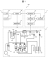
- FIG. 1 is a configuration diagram of an analysis device according to a first embodiment.
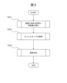
- 5 is a flowchart showing a processing procedure of a waveform acquiring unit and a waveform analyzing unit according to the first embodiment.
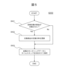
- 5 is a flowchart showing a procedure for acquiring a time history waveform of an electromotive force and calculating a feature amount according to the first embodiment.
- 4 is a graph showing a method for calculating a feature amount of a time history waveform of an electromotive force according to the first embodiment.
- 5 is a flowchart showing a procedure for managing the acquisition time of an electromotive force waveform according to the first embodiment.
- 5 is a flowchart showing a processing procedure for abnormality determination according to the first embodiment.
- 4 is a graph showing an anomaly determination method using a change over time in a feature amount of an electromotive force waveform according to the first embodiment;
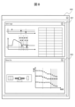
- FIG. 4 is a diagram showing an example of a display screen output to a display unit according to the first
- FIG. 1 is a diagram showing the configuration of an analysis device 100 according to the first embodiment.
- the analysis device 100 includes an electrolyte analysis unit 1, an electromotive force waveform processing unit 2, and a device control unit 3.
- the analysis device 100 is a device that measures the electrolyte concentration in a sample, and executes a method for determining the presence or absence of an abnormality in the analysis device 100.
- the electrolyte analysis unit 1 includes: - a plurality of ion selective electrodes 101 (for example, three types: a chloride ion electrode 101a, a potassium ion electrode 101b, and a sodium ion electrode 101c) that generate a potential corresponding to the ion concentration in the sample; a reference electrode 104 for generating a constant reference potential so that the potential of the ion-selective electrode 101 can be measured as a potential difference (electromotive force); - a sipper tube 102 which constitutes a flow path between the ion selective electrode 101 and the reference electrode 104 and is an example of a replacement part which is periodically replaced; a pinch valve 105 for opening and closing the flow path of the sipper tube 102; - a dilution tank 110 for storing an internal standard solution and a measurement solution (hereinafter referred to as a "specimen" or sometimes referred to as a sample) in which a specimen and a dilution solution are mixed;
- the three types of ion selective electrodes 101 each obtain a potential based on the concentration of the corresponding electrolyte.
- the comparison electrode 104 obtains a potential based on the reference liquid.
- various flow paths are configured in the analysis device 100, and these flow paths supply the sample or reference liquid to the ion selective electrodes 101 and the comparison electrode 104.
- the electromotive force waveform processing unit 2 includes: a potential measuring unit 20 for measuring the potential difference (electromotive force) between the ion selective electrode 101 and the reference electrode 104; a waveform acquisition unit 21 that constantly acquires the potential change of the electromotive force measured by the potential measurement unit 20 as a time history waveform and calculates a feature amount obtained from the acquired waveform; A waveform storage unit 22 that stores the waveform and feature values acquired by the waveform acquisition unit 21; a waveform analysis unit 23 that performs an abnormality determination using the waveform and feature values stored in the waveform storage unit 22 and stores parameters used for the abnormality determination in the waveform storage unit 22; Equipped with.
- the potential measuring unit 20 measures the electromotive force between the potential acquired by one of the ion selective electrodes 101 and the potential acquired by the comparison electrode 104.
- the waveform acquiring unit 21 acquires a waveform that represents the change in electromotive force.
- the waveform analyzing unit 23 performs analysis using the change in electromotive force and determines the presence or absence of an abnormality based on the characteristic amount of the waveform.
- the waveform memory unit 22 stores the waveform and the characteristic amount.
- the device control unit 3 A control unit 30 that controls the entire analysis device 100; A drive control unit 31 connected to the control unit 30 and controlling signal input/output for operating various drive units mounted on the analysis device 100; an input unit 32 connected to the control unit 30 and configured as a device such as a mouse, keyboard, or touch panel for a user of the analysis device 100 to input operation instructions and various parameters; a display unit 33 connected to the control unit 30 and displaying the state of the analysis device 100 including the processing results of the waveform analysis unit 23 using a GUI or the like; Equipped with.
- the control unit 30 has, for example, a hardware configuration as a known computer, and is equipped with, for example, a calculation means and a storage means.
- the calculation means includes, for example, a processor
- the storage means includes, for example, a storage medium such as a semiconductor memory device and a magnetic disk device. Some or all of the storage medium may be a non-transitory storage medium.
- the storage means may store a program.
- the processor executes this program, causing the computer to function as the control unit 30.
- a drive control unit 31 controls the input and output of signals for operating these drive units.
- the drive control unit 31 outputs a control signal to one or more drive units in association with each of a plurality of drive timings related to the part to be replaced.
- all of the drive units may be the parts to be replaced, only some of the drive units may be the parts to be replaced, or structures other than the drive units may be included in the parts to be replaced.
- FIG. 2 is a flowchart showing the processing steps of the waveform acquisition unit 21 and the waveform analysis unit 23.
- the waveform acquisition unit 21 constantly acquires the potential change of the electromotive force measured by the potential measurement unit 20 as a time history waveform (hereinafter, electromotive force waveform), and calculates the feature quantity obtained from the acquired waveform (S201).
- FIG. 3 is a flowchart showing the procedure for acquiring an electromotive force waveform and calculating a feature quantity by the waveform acquisition unit 21 according to the first embodiment.
- the waveform acquisition unit 21 starts the process of converting the electromotive force measured by the potential measurement unit 20 into a digital value and continuously acquiring it as a time history waveform (S301).
- the waveform acquisition unit 21 detects the operation timing of various drive parts mounted on the electrolyte analysis unit 1 after executing process S301 (i.e., while the waveform is being acquired) (S302 ⁇ Yes), it calculates the peak value and the time at which the peak value was reached (hereinafter, the peak time) as feature quantities from the electromotive force waveform before and after the time of the operation timing (S303).
- the detection of the operation timing may be performed based on the transmission of a timing signal (e.g., a trigger signal via communication) from the control unit 30 and on drive timing information of various drive units that is preset in the waveform acquisition unit 21 based on the timing information.
- a timing signal e.g., a trigger signal via communication
- step S303 The method for calculating the feature quantities in step S303 will now be described in detail with reference to FIG. 4.
- FIG. 4 is a graph showing a method for calculating the characteristic quantities of the electromotive force waveform of the waveform acquisition unit 21 according to the first embodiment. The example in FIG. 4 is used when determining an abnormality in the sipper tube 102.
- FIG. 4(a) shows the drive timing detected by the waveform acquisition unit 21, and FIG. 4(b) shows an example of the peak value and peak time calculated in synchronization with the drive timing.
- the comparison liquid suction, pinch valve drive, and sipper nozzle drive are described as examples of drive timing in the operating sequence of the drive unit mounted on the flow path of the sipper tube 102, which is a replacement part that is replaced periodically.
- the drive timing in FIG. 4(a) is part of the operation sequence for supplying the reference electrode solution to the flow path of the reference electrode 104.
- the “comparison liquid suction” drive timing consists of opening solenoid valves 121 and 122, closing pinch valve 105, and driving sipper syringe pump 133.
- the drive timing "pinch valve drive” includes the opening of the pinch valve 105, which is performed as part of the operation when introducing the sample in the dilution tank 110 into the flow path of the ion selective electrode 101.
- the drive timing "sipper nozzle drive” is also part of the operation when introducing the sample in the dilution tank 110 into the flow path of the ion selective electrode 101, and includes lowering the sipper nozzle 107.
- any abnormality in the sipper tube 102 is determined based on the waveforms related to these drive timings.
- the association between the drive timings and the replacement parts (for example, when determining whether there is an abnormality in the sipper tube 102, which is a replacement part, the comparison liquid suction, pinch valve drive, and sipper nozzle drive are referenced as the drive timing) is stored, for example, in the waveform analysis unit 23.
- the peak value and peak time are calculated in synchronization with the drive timing of the pinch valve drive (time t1) and the drive timing of the shipper nozzle drive (time t2).
- Figure 4(b) shows examples of calculations of the peak value (E1) and peak time (T1) of the electromotive force waveform synchronized with time t1, and the peak value (E2) and peak time (T2) of the electromotive force waveform synchronized with time t2.
- peak time (T1) synchronized with time t1 means that the value of time T1 is expressed with time t1 as the reference, and as a specific example, the value of the elapsed time from time t1 to time T1 (or the negative value of the elapsed time from time T1 to time t1) is equal to T1.
- the waveform acquisition unit 21 searches for and calculates the peak of the electromotive force waveform within a peak detection time (Tw1), which is a time span based on a preset time t1 (for example, a time period including a specified time before and after time t1).
- Tw1 peak detection time
- the negative peak at time tp1 is calculated.
- T1 tp1 - t1.
- the waveform acquisition unit 21 searches for and calculates the peak of the electromotive force waveform within a peak detection time (Tw2), which is a time span based on a preset time t2 (for example, a time period including a predetermined time before and after time t2).
- Tw2 peak detection time
- the waveform acquisition unit 21 finally outputs the features (E1, E2, T1, T2) calculated up to that point as a peak value data set.
- the waveform acquisition unit 21 associates the acquired waveforms with each drive timing, detects waveform peaks that appear in the temporal vicinity of the drive timing, and calculates the feature amount.
- the feature amount is - the electromotive force at the peak (peak value (E1), peak value (E2) of the electromotive force waveform), and - the time (T1, T2) between the drive timing time (t1, t2) and the peak occurrence time (tp1, tp2),
- the feature may include only one of these.
- the waveform acquisition unit 21 stores the peak value data set in the waveform storage unit 22 (S304) and proceeds to step S305.
- step S302 If the operation timing of the various drive parts mounted on the electrolyte analysis unit 1 is not detected in step S302 (S302 ⁇ No), the process similarly proceeds to step S305.
- the waveform acquisition unit 21 determines whether the analysis operation of the analysis device 100 has been completed, and if it has been completed (S305 ⁇ Yes), proceeds to step S306, and if it has not been completed (S305 ⁇ No), returns to step S302 and continues the processing operation.
- the waveform acquisition unit 21 performs statistical processing (e.g., calculation of the average value, variance, standard deviation, etc. for each of E1 and T1) on peak value data sets that have the same type of drive timing (e.g., E1 and T1 corresponding to "pinch valve drive") among the multiple acquired peak value data sets, and stores the results in the waveform storage unit 22 (S306).
- statistical processing e.g., calculation of the average value, variance, standard deviation, etc. for each of E1 and T1
- E1 and T1 corresponding to "pinch valve drive
- the waveform acquisition unit 21 may sequentially store the acquired electromotive force waveform and drive timing in the waveform storage unit 22.
- the waveform acquisition unit 21 may store the electromotive force waveforms and drive timings after performing statistical processing using multiple acquired electromotive force waveforms and drive timings.
- electromotive force monitoring data The above-mentioned peak value data set, together with the electromotive force waveform and/or drive timing, is referred to as electromotive force monitoring data.
- processing S304 and processing S306 are stored in the waveform storage unit 22, but it is also possible to pass the results of processing S304 and processing S306 to the waveform analysis unit 23 without using the waveform storage unit 22, and to perform abnormality determination by processing of the waveform analysis unit 23 described below.
- the waveform acquisition unit 21 manages the timestamp, which is the long-term time (units of year, month, day, and hour) of the electromotive force waveform and peak value data set stored in the waveform storage unit 22.
- FIG. 5 is a flowchart showing the procedure for managing the acquisition time of the electromotive force waveform according to the first embodiment.
- the waveform acquisition unit 21 determines whether or not a replacement part (e.g., the sipper tube 102) input via the input unit 32 has been replaced (S501). For example, data on when a user replaces a replacement part is recorded separately, and the waveform acquisition unit 21 refers to this data to determine whether or not a replacement has been performed. If a replacement has been performed (S501 ⁇ Yes), the replacement date and time of the target replacement part is updated and stored in the waveform storage unit 22 (S502); if no replacement has been performed (S501 ⁇ No), the process proceeds to S503.
- a replacement part e.g., the sipper tube 102
- the waveform acquisition unit 21 stores a timestamp, which is a set of information including the time of processing and the elapsed time since the replacement date and time of each replacement part, in association with the electromotive force monitoring data stored in the waveform storage unit 22 (S503).
- the waveform analysis unit 23 uses the electromotive force monitoring data stored in the waveform storage unit 22 and the time stamp to determine whether there is an abnormality in the electrolyte analysis unit 1, such as a defective replacement part (S203).
- FIG. 6 is a flowchart showing the procedure for determining an abnormality according to the first embodiment.
- parameters such as thresholds that are preset in the waveform analysis unit 23 via the input unit 32 are compared with the peak value data set stored in the waveform storage unit 22 (S601).
- This comparison is performed based on the relative amount (E1(t)-E2(t)) of the two peak values, as described below in relation to FIG. 7, for example. If this relative amount is within a predetermined normal range, the comparison result is determined to be within the normal range, and if the relative amount is outside the normal range, the comparison result is determined to be outside the normal range.
- the normal range can be determined appropriately by a person skilled in the art for each type of drive timing, for example.
- process S602 if the comparison result of process S601 is within the normal range (S602 ⁇ Yes), the process proceeds to process S603, and if it is not within the normal range (S602 ⁇ No), the process proceeds to process S608.
- process S603 it is determined whether a replacement part has been replaced since the process in FIG. 6 was last executed. For example, this determination is made by comparing the replacement date and time in S502 in FIG. 5 with the timestamp in S503 in FIG. 5. If a part has been replaced (S603 ⁇ Yes), a comparison is made between the latest electromotive force monitoring data and the previous value of the electromotive force monitoring data (i.e., the value before replacement) (S604). If a part has not been replaced (S603 ⁇ No), the process proceeds to process S606.
- a normal range is determined as a predetermined range based on the previous value of the electromotive force monitoring data, and it is determined, for example, whether the amount of change from the previous value is equal to or less than a predetermined allowable value or allowable ratio. As a specific example, the determination is made based on the amount of change in the relative amount (E1(t)-E2(t)) of the two peak values, as described later in relation to FIG. 7.
- process S605 if the latest electromotive force monitoring data in process S604 is within the normal range (for example, if the amount of change from the previous time is less than a predetermined tolerance value or less than an allowable ratio) (S605 ⁇ Yes), the process proceeds to process S606, and if it is not within the normal range (for example, if the amount of change from the previous time exceeds a predetermined tolerance value or more than an allowable ratio) (S605 ⁇ No), the process proceeds to process S608.
- step S606 the amount of change and trend of change over time in the characteristic quantities, etc. are calculated from the history of electromotive force monitoring data and the timestamps, and an abnormality is determined from the calculated amount of change and trend of change.
- FIG. 7 is a graph showing a method for determining an abnormality using the change over time in the electromotive force waveform calculated by the waveform analysis unit 23 according to the first embodiment.
- Figure 7(a) shows an example of time-dependent changes and anomaly determination using electromotive force monitoring data, and is a graph showing the time-dependent changes in two peak values (E1(t), E2(t)) and the time-dependent changes in the relative amount of the two peak values (E1(t) - E2(t)).
- the relative amount of the peak values (E1(t) - E2(t)) changes at times Ta and Tb.
- the threshold value for determining the amount of change is set in advance in the waveform analysis unit 23, and may be set via the input unit 32.
- the change trends Wa and Wb can be confirmed in the relative amounts of the peak values (E1(t) - E2(t)), respectively.
- the change at time Ta is temporary.
- the value of the relative quantity (E1(t)-E2(t)) changes temporarily and then returns to the value before the change (or within a specified range based on the value before the change) within a specified time, it is determined to be a measurement disturbance and is not determined to be an abnormality in the replaced part.
- the change at time Tb continues for more than a certain period of time.
- the value of the relative quantity (E1(t)-E2(t)) changes and does not return to the value before the change (or within a specified range based on the value before the change) even after a specified time has passed, it is determined that the replacement part has deteriorated, that is, that the replacement part is abnormal.
- the criteria for determining these change trends are set in advance in the waveform analysis unit 23, and may be set via the input unit 32.
- FIG. 7(b) also shows an example of time-dependent changes and anomaly determination using electromotive force monitoring data, and is a graph showing the time-dependent changes in two peak values (E1(t), E2(t)) and the time-dependent changes in the relative amount of the two peak values (E1(t)-E2(t)).
- the threshold value for determining the amount of change is set in advance in the waveform analysis unit 23, and may be set via the input unit 32.
- the relative amount of the peak values (E1(t) - E2(t)) shows no tendency to change after time Tc. In other words, the relative amount (E1(t) - E2(t)) remains constant even after time Tc.
- the change trend Wd continues for a certain period of time or more.
- the relative amount (E1(t) - E2(t)) continues to fluctuate for a certain period of time or more, it is determined that the replacement part has deteriorated, i.e., that the replacement part is abnormal.
- the reference duration for determining whether the change trend Wd continues may be changed depending on the time elapsed since the part replacement included in the timestamp.
- the criteria for determining these change trends are set in advance in the waveform analysis unit 23, and may be set via the input unit 32.
- step S606 if there is no abnormality in the judgment result of step S606 (S607 ⁇ Yes), the electrolyte analysis unit 1 judges that there is no abnormality and ends the process.
- step S606 if the determination result of step S606 is abnormal (S607 ⁇ No), proceed to step S608.
- Process S608 is executed when an abnormality is detected in at least one of the above-mentioned series of processes by the waveform analysis unit 23, and determines and notifies the location and degree of the abnormality.
- the determination of the abnormality varies depending on the processing step in which the waveform analysis unit 23 determines that an abnormality exists.
- an abnormality is determined in process S602 (S602 ⁇ No)
- the determination is based only on the feature amount at a specific time point, so it is determined that the degree of abnormality is the first abnormality level, which is greater than other abnormalities, and that an immediate response is required.
- the degree of abnormality is a second abnormality degree that is smaller than the first abnormality degree because the determination was made before and after the part was replaced, and the replaced part (the part related to the corresponding drive timing) that is the abnormal part is identified and output.
- an abnormality is determined in process S607 (S607 ⁇ No)
- the determination is based on the change over time since the part was replaced, so the degree of abnormality is the second degree of abnormality, which is smaller than the first degree of abnormality, and the replaced part, which is the abnormal part, is identified and output.
- a comparison may also be made with the electromotive force monitoring data of each of the ion selective electrodes 101 (chloride ion electrode 101a, potassium ion electrode 101b, and sodium ion electrode 101c).
- the chloride ion electrode 101a may be included as a candidate for the abnormality location.
- step S608 a comparison may be made to determine whether there were any abnormalities during sample measurement.
- an abnormal value is found in the measurement result when measuring a sample, it can be determined that the degree of abnormality is large (for example, the first degree of abnormality) and that immediate action is required.
- the level of notification can also be changed according to the degree of abnormality in the sample measurement results. For example, at a certain degree of abnormality, a warning message is output and the device continues to operate, but at a higher degree of abnormality, the device stops operating. As another example, at a certain degree of abnormality, the device is allowed to restart unconditionally after it has stopped, but at a higher degree of abnormality, restarting the device is prohibited until a replacement part determined to be abnormal is replaced.
- the analysis device 100 determines whether or not there is an abnormality.
- the abnormality determination is performed in relation to each of a plurality of drive timings related to the part to be replaced, it is possible to appropriately detect defects in the replacement part.
- the association between the drive timing and the part to be replaced can be defined appropriately by a person skilled in the art depending on the configuration of the analysis device, etc.
- by associating structures other than the drive unit as parts to be replaced with one of the drive timings it is possible to detect abnormalities in parts that are not the drive unit.
- the shipper nozzle 107 is not a driving unit, by associating the shipper nozzle 107 with driving timings that may be affected by an abnormality in the shipper nozzle 107 (for example, the driving timing "comparison liquid suction", the driving timing “pinch valve driving”, and/or the driving timing "sipper nozzle driving” in FIG. 4(a)), it is possible to detect an abnormality in the shipper nozzle 107.
- driving timings for example, the driving timing "comparison liquid suction", the driving timing "pinch valve driving”, and/or the driving timing "sipper nozzle driving" in FIG. 4(a)
- the waveform analysis unit 23 judges abnormalities based on changes over time in the feature values stored in the waveform storage unit 22. With this configuration, it is possible to properly detect abnormalities that cannot be detected by a single measurement.
- the waveform analysis unit 23 determines whether or not there is an abnormality after the part to be replaced has been replaced.
- the determination process in FIG. 6 can be performed before measuring the electrolyte concentration in the sample, in which case the presence or absence of an abnormality is determined before measuring the electrolyte concentration in the sample. This makes it possible to avoid any influence on the measurement of the sample.
- the waveform analysis unit 23 also determines whether or not there is an abnormality based on multiple feature values related to different types of drive timing (in the example of FIG. 7, feature value E1 related to the drive timing "pinch valve drive” and feature value E2 related to the drive timing "sipper nozzle drive”). With this configuration, it is possible to properly detect abnormalities that cannot be detected from a single type of drive.
- the waveform analysis unit 23 when it is determined that there is an abnormality, the waveform analysis unit 23: - a feature quantity relating to a waveform acquired during the measurement operation of the electrolyte concentration in the sample; - a feature quantity relating to a waveform acquired when the measurement of the electrolyte concentration in the sample is not in progress;
- the cause of the abnormality may be identified based on the above.
- feature E1 can be a feature related to a waveform acquired during sample measurement
- feature E2 can be a feature related to a waveform acquired when sample measurement is not in progress.
- the cause of the abnormality is identified and output in process S608 in FIG. 6. With this configuration, even an abnormality that becomes apparent only during sample measurement can be properly detected.
- FIG. 8 is a diagram showing an example of a display screen 800 output to the display unit 33 according to the first embodiment.
- the display screen 800 includes a setting input screen 801 and a result display screen 802.
- the setting input screen 801 displays the settings for the calculation processing of the waveform acquisition unit 21 and the waveform analysis unit 23 and the abnormality determination processing that are set using the input unit 32.
- the result display screen 802 displays the electromotive force waveform stored in the waveform storage unit 22 and a graph showing the change over time in the characteristic quantities of the electromotive force waveform.
- the result display screen 802 displays the judgment results including the abnormal location and the degree of abnormality judged by the waveform analysis unit 23.
- this embodiment can reduce the amount of work required to manually check for defects and deterioration of replacement parts, including the sipper tube 102 of the electrolyte analysis unit 1.
- Sipper nozzle (drive unit) 108 Dilution solution supply nozzle 109: Internal standard solution supply nozzle 110: Dilution tank 111: Waste liquid tank 112: Vacuum pump (drive unit) 121 to 127: Solenoid valve (drive unit) 131... Syringe pump for internal standard solution (drive unit) 132...Dilution liquid syringe pump (drive unit) 133... Sipper syringe pump (drive unit) 141: Internal standard solution bottle 151: Dilution solution bottle 161: Reference electrode solution bottle 800: Display screen 801: Setting input screen 802: Result display screen E1: Peak value (feature amount) E2: Peak value (feature value) T1: Time (feature value) T2: Time (feature value)
Landscapes
- Chemical & Material Sciences (AREA)
- Life Sciences & Earth Sciences (AREA)
- Health & Medical Sciences (AREA)
- Physics & Mathematics (AREA)
- Chemical Kinetics & Catalysis (AREA)
- Electrochemistry (AREA)
- Molecular Biology (AREA)
- Analytical Chemistry (AREA)
- Biochemistry (AREA)
- General Health & Medical Sciences (AREA)
- General Physics & Mathematics (AREA)
- Immunology (AREA)
- Pathology (AREA)
- Automatic Analysis And Handling Materials Therefor (AREA)
Priority Applications (2)
| Application Number | Priority Date | Filing Date | Title |
|---|---|---|---|
| JP2025533943A JPWO2025018126A1 (https=) | 2023-07-19 | 2024-06-28 | |
| CN202480014577.XA CN120752524A (zh) | 2023-07-19 | 2024-06-28 | 分析装置以及判定有无异常的方法 |
Applications Claiming Priority (2)
| Application Number | Priority Date | Filing Date | Title |
|---|---|---|---|
| JP2023-117789 | 2023-07-19 | ||
| JP2023117789 | 2023-07-19 |
Publications (1)
| Publication Number | Publication Date |
|---|---|
| WO2025018126A1 true WO2025018126A1 (ja) | 2025-01-23 |
Family
ID=94281337
Family Applications (1)
| Application Number | Title | Priority Date | Filing Date |
|---|---|---|---|
| PCT/JP2024/023542 Pending WO2025018126A1 (ja) | 2023-07-19 | 2024-06-28 | 分析装置および異常の有無を判定する方法 |
Country Status (3)
| Country | Link |
|---|---|
| JP (1) | JPWO2025018126A1 (https=) |
| CN (1) | CN120752524A (https=) |
| WO (1) | WO2025018126A1 (https=) |
Cited By (1)
| Publication number | Priority date | Publication date | Assignee | Title |
|---|---|---|---|---|
| WO2025258698A1 (ja) * | 2024-06-11 | 2025-12-18 | 株式会社日立ハイテク | 自動分析装置、異常検知システム及び異常検知方法 |
Citations (4)
| Publication number | Priority date | Publication date | Assignee | Title |
|---|---|---|---|---|
| JP2004219352A (ja) * | 2003-01-17 | 2004-08-05 | Toshiba Corp | 分析装置及び管理システム |
| JP2009121817A (ja) * | 2007-11-09 | 2009-06-04 | Olympus Corp | 分析装置 |
| JP2020041968A (ja) * | 2018-09-13 | 2020-03-19 | 株式会社日立ハイテクノロジーズ | 電解質濃度測定装置 |
| JP2021018141A (ja) * | 2019-07-19 | 2021-02-15 | 株式会社日立ハイテク | 分析装置及び分析方法 |
-
2024
- 2024-06-28 WO PCT/JP2024/023542 patent/WO2025018126A1/ja active Pending
- 2024-06-28 JP JP2025533943A patent/JPWO2025018126A1/ja active Pending
- 2024-06-28 CN CN202480014577.XA patent/CN120752524A/zh active Pending
Patent Citations (4)
| Publication number | Priority date | Publication date | Assignee | Title |
|---|---|---|---|---|
| JP2004219352A (ja) * | 2003-01-17 | 2004-08-05 | Toshiba Corp | 分析装置及び管理システム |
| JP2009121817A (ja) * | 2007-11-09 | 2009-06-04 | Olympus Corp | 分析装置 |
| JP2020041968A (ja) * | 2018-09-13 | 2020-03-19 | 株式会社日立ハイテクノロジーズ | 電解質濃度測定装置 |
| JP2021018141A (ja) * | 2019-07-19 | 2021-02-15 | 株式会社日立ハイテク | 分析装置及び分析方法 |
Cited By (1)
| Publication number | Priority date | Publication date | Assignee | Title |
|---|---|---|---|---|
| WO2025258698A1 (ja) * | 2024-06-11 | 2025-12-18 | 株式会社日立ハイテク | 自動分析装置、異常検知システム及び異常検知方法 |
Also Published As
| Publication number | Publication date |
|---|---|
| JPWO2025018126A1 (https=) | 2025-01-23 |
| CN120752524A (zh) | 2025-10-03 |
Similar Documents
| Publication | Publication Date | Title |
|---|---|---|
| US11782021B2 (en) | Electrolyte concentration measurement device | |
| JP5331669B2 (ja) | 電解質分析装置 | |
| US11002749B2 (en) | Calibration method | |
| CN112666234A (zh) | 电解质浓度测定装置、电解质浓度测定方法 | |
| US12326459B2 (en) | Automatic analyzer | |
| US20220099656A1 (en) | Method of detecting the presence or absence of a clot in a liquid sample analyzer | |
| US20220042972A1 (en) | Method of detecting presence or absence of a clot in a liquid sample analyzer | |
| CN114127549A (zh) | 分析装置以及分析方法 | |
| WO2025018126A1 (ja) | 分析装置および異常の有無を判定する方法 | |
| JP2018146586A (ja) | 分析物濃度を決定する方法 | |
| US20220283195A1 (en) | Automatic analysis device | |
| CN111788479B (zh) | 自动分析装置、自动分析方法 | |
| JP2001004586A (ja) | 電解質分析装置 | |
| US12601711B2 (en) | Automated analysis apparatus | |
| JP5427975B2 (ja) | 電解質分析装置の管理システム | |
| WO2020217750A1 (ja) | 自動分析装置 | |
| EP4481391A1 (en) | Component abnormality detecting system, automated analyzing device, and component abnormality detecting method | |
| CN117616283A (zh) | 自动分析装置以及自动分析装置的试剂管理方法 | |
| JP6738717B2 (ja) | 分析処理システム及び分析処理方法 | |
| EP4722726A1 (en) | Automatic analyzer and measuring method using the same | |
| WO2025134483A1 (ja) | 自動分析装置、及び自動分析装置の電解質測定方法 | |
| CN117825471A (zh) | 样本分析仪及其控制方法 |
Legal Events
| Date | Code | Title | Description |
|---|---|---|---|
| DPE2 | Request for preliminary examination filed before expiration of 19th month from priority date (pct application filed from 20040101) | ||
| 121 | Ep: the epo has been informed by wipo that ep was designated in this application |
Ref document number: 24842921 Country of ref document: EP Kind code of ref document: A1 |
|
| ENP | Entry into the national phase |
Ref document number: 2025533943 Country of ref document: JP Kind code of ref document: A |
|
| WWE | Wipo information: entry into national phase |
Ref document number: 2025533943 Country of ref document: JP |
|
| WWE | Wipo information: entry into national phase |
Ref document number: 202480014577.X Country of ref document: CN |
|
| WWP | Wipo information: published in national office |
Ref document number: 202480014577.X Country of ref document: CN |
|
| NENP | Non-entry into the national phase |
Ref country code: DE |