WO2025017819A1 - 送風機及び換気装置 - Google Patents
送風機及び換気装置 Download PDFInfo
- Publication number
- WO2025017819A1 WO2025017819A1 PCT/JP2023/026192 JP2023026192W WO2025017819A1 WO 2025017819 A1 WO2025017819 A1 WO 2025017819A1 JP 2023026192 W JP2023026192 W JP 2023026192W WO 2025017819 A1 WO2025017819 A1 WO 2025017819A1
- Authority
- WO
- WIPO (PCT)
- Prior art keywords
- value
- output
- control device
- correction data
- motor
- Prior art date
- Legal status (The legal status is an assumption and is not a legal conclusion. Google has not performed a legal analysis and makes no representation as to the accuracy of the status listed.)
- Pending
Links
Images




Classifications
-
- F—MECHANICAL ENGINEERING; LIGHTING; HEATING; WEAPONS; BLASTING
- F04—POSITIVE - DISPLACEMENT MACHINES FOR LIQUIDS; PUMPS FOR LIQUIDS OR ELASTIC FLUIDS
- F04D—NON-POSITIVE-DISPLACEMENT PUMPS
- F04D27/00—Control, e.g. regulation, of pumps, pumping installations or pumping systems specially adapted for elastic fluids
-
- F—MECHANICAL ENGINEERING; LIGHTING; HEATING; WEAPONS; BLASTING
- F24—HEATING; RANGES; VENTILATING
- F24F—AIR-CONDITIONING; AIR-HUMIDIFICATION; VENTILATION; USE OF AIR CURRENTS FOR SCREENING
- F24F7/00—Ventilation
Definitions
- This disclosure relates to blowers and ventilation devices.
- the motor rank is selected according to the number of rotations of the DC motor for a certain applied voltage.
- a data table corresponding to the motor rank is stored in the table storage unit.
- the data table is a table showing the relationship between the applied voltage and the number of rotations.
- the air volume control unit controls the air volume based on the set air volume and the data table (see, for example, Patent Document 1).
- This disclosure has been made to solve the above problems, and aims to provide a blower and ventilator that can reduce variations in air volume between products.
- the blower according to the present disclosure includes a fan, a DC motor that drives the fan, and a control device that controls the DC motor by inputting an output instruction to the DC motor, and the operation modes of the DC motor controlled by the control device include a normal operation mode and a correction data acquisition mode, and the control device stores reference instruction data that indicates the relationship between the output instruction value and the output value of the DC motor relative to the output instruction value, and in the correction data acquisition mode, the control device inputs an output instruction to the DC motor and calculates correction data based on the output instruction value input to the DC motor and the actual output value of the DC motor, and in the normal operation mode, uses a corrected instruction value, which is a value obtained by correcting the output instruction value in the reference instruction data using the correction data, as the output instruction value.
- FIG. 1 is a block diagram showing a schematic configuration of a blower used in a ventilation device according to a first embodiment.
- FIG. 4 is a graph showing an output value versus an output instruction value in the case where a correction process is not performed by the control device main body of FIG. 1 .
- 2 is a graph showing an output value versus an output instruction value when a correction process is performed by the control device main body of FIG. 1 .
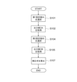
- 4 is a flowchart showing a correction data acquisition process performed by the control device main body of FIG. 1 .
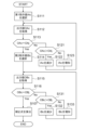
- 10 is a flowchart showing a first modified example of the correction data acquisition process performed by the control device main body of FIG. 1 .
- 10 is a flowchart showing a second modified example of the correction data acquisition process performed by the control device main body of FIG.
- FIG. 1 . 2 is a configuration diagram showing a first example of a processing circuit that realizes each function of the control device main body of the first embodiment.
- FIG. 11 is a configuration diagram showing a second example of a processing circuit that realizes each function of the control device main body of the first embodiment.
- Embodiment 1. 1 is a block diagram showing a schematic configuration of a blower used in a ventilation device according to embodiment 1.
- the blower includes a fan 11, a DC motor 12, and a control device 13.
- the DC motor 12 drives the fan 11, causing the fan 11 to generate an airflow.
- the control device 13 controls the DC motor 12 by inputting output instructions to the DC motor 12.
- the control device 13 has a control device main body 14, an output instruction circuit 15, and an output detection circuit 16.
- the control device main body 14 has, for example, a microcomputer.
- the control device main body 14 also has, as functional blocks, a memory unit 17, a calculation unit 18, and a mode switching unit 19.
- the memory unit 17 stores reference instruction data.
- the reference instruction data is data that indicates the relationship between the output instruction value for the DC motor 12 and the output value of the DC motor 12 relative to the output instruction value.
- the output instruction value is an instruction value corresponding to the volume of air generated by the fan 11.
- the output value is the rotation speed of the DC motor 12.
- the reference instruction data is stored in advance in the control device main body 14 for each model of ventilation device.
- the calculation unit 18 calculates the value of the output instruction.
- the output instruction circuit 15 inputs an output instruction to the DC motor 12 according to the calculation result by the calculation unit 18.
- the output detection circuit 16 detects the output value of the DC motor 12.
- the memory unit 17 stores the output value detected by the output detection circuit 16.
- the operation modes of the DC motor 12 controlled by the control device 13 include a normal operation mode and a correction data acquisition mode.
- the mode switching unit 19 switches the operation mode.
- control device 13 inputs an output instruction to the DC motor 12 and calculates correction data based on the value of the output instruction input to the DC motor 12 and the actual output value of the DC motor 12.
- the control device 13 uses a corrected instruction value, which is the output instruction value in the reference instruction data corrected by the correction data, as the output instruction value.
- control device main body 14 stores a reference relational equation as reference indication data.
- the control device main body 14 also calculates an actual relational equation as correction data.
- the control device main body 14 calculates a corrected indication value based on the reference relational equation and the actual relational equation.
- the reference relational equation shows the relationship between the output indication value and the output value in the reference product.
- the actual measurement relational equation shows the relationship between the output indication value and the output value in the target product.
- the target product is the ventilation device in embodiment 1.
- the reference product is a product for which a performance evaluation was performed to set the standard value in the target product.
- the reference equation and the measured equation are both linear functions.
- the output value is proportional to the output indication value. If the output indication value is ⁇ and the output value is N, the reference equation and the measured equation can be expressed as follows.
- N ⁇ base ⁇ ⁇ + ⁇ base ... reference relational formula
- control device main body 14 calculates the slope ⁇ and intercept ⁇ of the straight line represented by the actual measurement relationship equation from two or more output values obtained by two or more different output instructions.
- the control device main body 14 has a first set value IA and a second set value IB set as output instruction values to be input to the DC motor 12 in the correction data acquisition mode. That is, the memory unit 17 stores the first set value IA and the second set value IB.
- the second set value IB is a value greater than the first set value IA.
- the slope ⁇ and intercept ⁇ in the measured relational equation vary depending on the individual target product. For this reason, if the output indication value ⁇ required to obtain the desired output value N in the reference product is input as is into the measured relational equation, the obtained output value N will differ from N in the reference relational equation. To make the output value N in the measured relational equation the same as the output value N in the reference relational equation, it is necessary to correct the output indication value input into the measured relational equation to the corrected indication value ⁇ .
- the control device main body 14 is set with an upper limit rotation speed Nhigh as the upper limit value of the output value N.
- the control device main body 14 is also set with a lower limit rotation speed Nlow as the lower limit value of the output value N.
- the memory unit 17 stores the upper limit rotation speed Nhigh and the lower limit rotation speed Nlow.
- the control device main body 14 When the output value N is equal to or less than the lower limit rotation speed Nlow in the correction data acquisition mode, the control device main body 14 increases the value of the output instruction until the output value N is greater than the lower limit rotation speed Nlow. Also, when the output value N is equal to or greater than the upper limit rotation speed Nhigh in the correction data acquisition mode, the control device main body 14 decreases the value of the output instruction until the output value N is smaller than the upper limit rotation speed Nhigh.
- the first instruction value IAc, the second instruction value IBc, the first judgment value OAj, the second judgment value OBj, and the set correction amount are set in the control device main body 14. That is, the memory unit 17 stores the first instruction value IAc, the second instruction value IBc, the first judgment value OAj, the second judgment value OBj, and the set correction amount.
- the first instruction value IAc is a value greater than the first set value IA.
- the second instruction value IBc is a value less than the second set value IB.
- the second instruction value IBc is also a value greater than the first instruction value IAc.
- the first judgment value OAj is a value greater than the lower limit rotation speed Nlow.
- the second judgment value OBj is a value less than the upper limit rotation speed Nhigh.
- control device main body 14 selects the first instruction value IAc and the second instruction value IBc as the output instruction values.
- control device main body 14 decreases or increases the first instruction value IAc by the set correction amount so that the output value OAc at the first instruction value IAc becomes the same as the first judgment value OAj.
- the control device main body 14 also decreases or increases the second instruction value IBc by the set correction amount so that the output value OBc at the second instruction value IBc becomes the same as the second judgment value OBj.
- the control device main body 14 stores the first indication value IAc when the output value OAc becomes the same as the first judgment value OAj, and the second indication value IBc when the output value OBc becomes the same as the second judgment value OBj.
- the control device main body 14 then calculates the actual measurement relational equation from the stored first indication value IAc, the stored second indication value IBc, the first judgment value OAj, and the second judgment value OBj.
- the control device main body 14 automatically starts operating the DC motor 12 in the correction data acquisition mode. Then, the control device main body 14 starts operating the DC motor 12 in the normal operation mode after calculating the correction data.
- the control device main body 14 can also receive an external command to start the correction data acquisition mode.
- the command is input, for example, by operating a reset switch.
- the control device main body 14 receives an external command to start the correction data acquisition mode, it starts operating the DC motor 12 in the correction data acquisition mode.
- the control device main body 14 then updates the correction data after calculating it.
- control device main body 14 closes the air intake and exhaust ports, thereby closing the flow path of the airflow generated by the fan 11.
- FIG. 2 is a graph showing the output value versus the value of the output instruction when the correction process by the control device main body 14 of FIG. 1 is not performed.
- FIG. 3 is a graph showing the output value versus the value of the output instruction when the correction process by the control device main body 14 of FIG. 1 is performed.
- the solid line indicates the output value for the reference product.
- the dotted line indicates the output value for target product A.
- the dashed-dotted line indicates the output value for target product B.
- the circles on the solid line, the squares on the dotted line, and the triangles on the dashed-dotted line each indicate the output instruction values when attempting to obtain the same air volume F1.
- the reference product, target product A, and target product B all have the same output indication value corresponding to air volume F1. Therefore, due to variations in the DC motor 12, output indication circuit 15, etc., the output values in target product A and target product B differ from the output value in the reference product. Therefore, there is variation in the air volumes generated between the reference product, target product A, and target product B.
- the correction process corrects the output instruction value corresponding to air volume F1 in target product A and target product B to a value different from the output instruction value corresponding to air volume F1 in the reference product.
- the output values in target product A and target product B are each the same as the output values in the reference product. Therefore, the variation in the air volumes generated by the reference product, target product A, and target product B is suppressed.
- FIG. 4 is a flowchart showing the correction data acquisition process by the control device main body 14 of FIG. 1.
- the control device main body 14 starts the correction data acquisition process of FIG. 4.
- step S101 the control device main body 14 selects the first set value IA as the output instruction value.
- the output instruction circuit 15 inputs an output instruction corresponding to the output instruction value to the DC motor 12. In other words, a voltage corresponding to the output instruction value is applied to the DC motor 12.
- step S102 the control device main body 14 acquires and stores the output value OA from the output detection circuit 16.
- the output value OA is the rotation speed of the DC motor 12 at the first set value IA.
- step S103 the control device main body 14 determines whether the output value OA is greater than the lower limit rotation speed Nlow.
- control device main body 14 selects the second set value IB as the output instruction value in step S104.
- step S105 the control device main body 14 acquires and stores the output value OB from the output detection circuit 16.
- the output value OB is the rotation speed of the DC motor 12 at the second set value IB.
- step S106 the control device main body 14 determines whether the output value OB is less than the upper limit rotation speed Nhigh.
- control device main body 14 calculates a correction formula for calculating the corrected instruction value ⁇ in step S107 and ends the process.
- control device main body 14 calculates the slope ⁇ and intercept ⁇ in the actual measurement relationship equation for the target product based on the first set value IA, the second set value IB, the output value OA, and the output value OB.
- the correction equation is then calculated from the reference equation and the measured equation.
- step S103 If it is determined in step S103 that the output value OA is equal to or less than the lower limit rotation speed Nlow, the control device main body 14 selects the first instruction value IAc as the value of the output instruction in step S111. If it is determined in step S106 that the output value OB is equal to or greater than the upper limit rotation speed Nhigh, the control device main body 14 also proceeds to the process of step S111.
- the control device main body 14 After selecting the first instruction value IAc, the control device main body 14 acquires and stores the output value OAc from the output detection circuit 16 in step S112.
- the output value OAc is the number of rotations of the DC motor 12 at the first instruction value IAc.
- step S113 the control device main body 14 determines whether the output value OAc is the same as the first judgment value OAj. At this time, if the difference between the output value OAc and the first judgment value OAj is within a set range, it may be determined that the output value OAc is the same as the first judgment value OAj.
- control device main body 14 selects the second instruction value IBc as the output instruction value in step S114.
- step S115 the control device main body 14 obtains and stores the output value OBc from the output detection circuit 16.
- the output value OBc is the number of rotations of the DC motor 12 at the second instruction value IBc.
- step S116 the control device main body 14 determines whether the output value OBc is the same as the second judgment value OBj. At this time, if the difference between the output value OBc and the second judgment value OBj is within a set range, it may be determined that the output value OBc is the same as the second judgment value OBj.
- control device main body 14 calculates the correction formula in step S107 and ends the process.
- control device main body 14 calculates the slope ⁇ and intercept ⁇ in the actual measurement relational equation of the target product based on the first indication value IAc, the second indication value IBc, the first judgment value OAj, and the second judgment value OBj.
- the output value OAc determined to be the same as the first judgment value OAj may be used.
- the output value OBc determined to be the same as the second judgment value OBj may be used.
- step S113 If it is determined in step S113 that the output value OAc is not equal to the first judgment value OAj, the control device main body 14 determines in step S121 whether the output value OAc is greater than the first judgment value OAj.
- the control device main body 14 decreases the first instruction value IAc by the set correction amount in step S122. If the output value OAc is less than the first judgment value OAj, the control device main body 14 increases the first instruction value IAc by the set correction amount in step S123.
- step S112. the control device main body 14 acquires the output value OAc at the first instruction value IAc after the decrease or increase. Then, in step S113, the control device main body 14 again determines whether the output value OAc is the same as the first judgment value OAj.
- step S116 If it is determined in step S116 that the output value OBc is not equal to the second judgment value OBj, the control device main body 14 determines in step S131 whether the output value OBc is greater than the second judgment value OBj.
- the control device main body 14 decreases the second instruction value IBc by the set correction amount in step S132. If the output value OBc is less than the second judgment value OBj, the control device main body 14 increases the second instruction value IBc by the set correction amount in step S133.
- step S115 the control device main body 14 acquires the output value OBc at the second instruction value IBc after the decrease or increase. Then, in step S116, the control device main body 14 again determines whether the output value OBc is the same as the second judgment value OBj.
- the control device 13 calculates the correction formula in step S107 and ends the process.
- the operation modes of the DC motor 12 controlled by the control device 13 include a normal operation mode and a correction data acquisition mode.
- the control device 13 inputs an output instruction to the DC motor 12 and calculates correction data based on the value of the output instruction input to the DC motor 12 and the actual output value of the DC motor 12.
- the control device 13 uses, as the value of the output instruction, a corrected instruction value ⁇ , which is a value obtained by correcting the value of the output instruction in the reference instruction data using the correction data.
- the control device 13 also stores a reference relational equation as reference indication data. In the correction data acquisition mode, the control device 13 calculates the actual relational equation. In the normal operation mode, the control device 13 calculates the corrected indication value ⁇ based on the reference relational equation and the actual relational equation. Therefore, the corrected indication value ⁇ can be calculated with a simple configuration, and variations in air volume between products can be easily suppressed.
- control device 13 calculates the slope ⁇ and intercept ⁇ in the actual measurement relational equation from two or more output values obtained by two or more different output instructions. Therefore, the actual measurement relational equation can be easily calculated by simple processing.
- the control device 13 increases the value of the output instruction until the output value becomes greater than the lower limit rotation speed Nlow. In addition, in the correction data acquisition mode, if the output value is equal to or higher than the upper limit rotation speed Nhigh, the control device 13 decreases the value of the output instruction until the output value becomes smaller than the upper limit rotation speed Nhigh.
- the control device 13 automatically starts operating the DC motor 12 in the correction data acquisition mode. Then, after calculating the correction data, the control device 13 starts operating the DC motor 12 in the normal operation mode.
- control device 13 when the control device 13 receives an external instruction to start the correction data acquisition mode, it starts operating the DC motor 12 in the correction data acquisition mode, and updates the correction data after calculating it.
- correction data can be updated as needed, for example when the DC motor 12 is replaced or when it is determined that the correction data needs to be updated, making it possible to suppress variations in air volume between products over the long term.
- the control device 13 closes the flow path of the airflow generated by the fan 11. This results in the air volume of the ventilation device being 0 m3 /h and the external static pressure being at its maximum, making it possible to suppress fluctuations in the external static pressure caused by differences in loss resistance in the duct connected to the ventilation device. This makes it possible to carry out correction control of the target product under the same conditions as the reference product, enabling more precise suppression of variation.
- workers may close at least one of the ventilation device's intake and exhaust ports using tape, a shielding plate, a damper inside the device, etc.
- FIG. 5 is a flowchart showing a first modified example of the correction data acquisition process by the control device main body 14 of FIG. 1.
- the processes of steps S103 and S106 in FIG. 4 are omitted. Accordingly, in the first modified example, the processes from step S111 onwards are also omitted.
- FIG. 6 is a flow chart showing a second modified example of the correction data acquisition process by the control device main body 14 of FIG. 1.
- the process of step S111 in FIG. 4 is started. Therefore, the processes from step S101 to step S106 in FIG. 4 are omitted.
- output adjustment may be performed from the beginning based on the first judgment value OAj and the second judgment value OBj, as shown in Figure 6.
- the output value of the DC motor is not limited to the rotation speed of the DC motor 12, but may be, for example, the current value of the DC motor 12.
- the measured relational equation may also be calculated from output value data obtained by, for example, continuously changing the value of the output instruction within a set range.
- the reference indication data may also be stored in the control device 13 as a reference data table.
- the relationship between the corrected indication value and the output value may also be stored in the control device 13 as a corrected data table.
- the blower may also be used for purposes other than ventilation equipment.
- FIG. 7 is a configuration diagram showing a first example of a processing circuit that realizes each function of the control device main body 14 in embodiment 1.
- the processing circuit 100 in the first example is dedicated hardware.
- the processing circuit 100 may be, for example, a single circuit, a composite circuit, a programmed processor, a parallel programmed processor, an ASIC (Application Specific Integrated Circuit), an FPGA (Field Programmable Gate Array), or a combination of these.
- Each function of the control device main body 14 may be realized by an individual processing circuit 100, or all the functions may be realized together by the processing circuit 100.
- FIG. 8 is a configuration diagram showing a second example of a processing circuit that realizes each function of the control device main body 14 in embodiment 1.
- the processing circuit 200 of the second example includes a processor 201 and a memory 202.
- each function of the control device main body 14 is realized by software, firmware, or a combination of software and firmware.
- the software and firmware are written as programs and stored in the memory 202.
- the processor 201 realizes each function by reading and executing the programs stored in the memory 202.
- memory 202 refers to non-volatile or volatile semiconductor memory, such as RAM (Random Access Memory), ROM (Read Only Memory), flash memory, EPROM (Erasable Programmable Read Only Memory), EEPROM (Electrically Erasable and Programmable Read Only Memory), etc. Also included in memory 202 are magnetic disks, flexible disks, optical disks, compact disks, mini disks, DVDs, etc.
- the processing circuit can realize the functions of each of the above-mentioned parts through hardware, software, firmware, or a combination of these.
Landscapes
- Engineering & Computer Science (AREA)
- Mechanical Engineering (AREA)
- General Engineering & Computer Science (AREA)
- Chemical & Material Sciences (AREA)
- Combustion & Propulsion (AREA)
- Control Of Electric Motors In General (AREA)
Priority Applications (2)
| Application Number | Priority Date | Filing Date | Title |
|---|---|---|---|
| PCT/JP2023/026192 WO2025017819A1 (ja) | 2023-07-18 | 2023-07-18 | 送風機及び換気装置 |
| JP2025533757A JPWO2025017819A1 (https=) | 2023-07-18 | 2023-07-18 |
Applications Claiming Priority (1)
| Application Number | Priority Date | Filing Date | Title |
|---|---|---|---|
| PCT/JP2023/026192 WO2025017819A1 (ja) | 2023-07-18 | 2023-07-18 | 送風機及び換気装置 |
Publications (1)
| Publication Number | Publication Date |
|---|---|
| WO2025017819A1 true WO2025017819A1 (ja) | 2025-01-23 |
Family
ID=94281780
Family Applications (1)
| Application Number | Title | Priority Date | Filing Date |
|---|---|---|---|
| PCT/JP2023/026192 Pending WO2025017819A1 (ja) | 2023-07-18 | 2023-07-18 | 送風機及び換気装置 |
Country Status (2)
| Country | Link |
|---|---|
| JP (1) | JPWO2025017819A1 (https=) |
| WO (1) | WO2025017819A1 (https=) |
Citations (3)
| Publication number | Priority date | Publication date | Assignee | Title |
|---|---|---|---|---|
| JP2007192495A (ja) * | 2006-01-20 | 2007-08-02 | Matsushita Electric Ind Co Ltd | 換気扇の風量制御装置 |
| CN112448643A (zh) * | 2019-09-05 | 2021-03-05 | 广州汽车集团股份有限公司 | 电机的角度误差补偿方法、装置、计算机设备及存储介质 |
| US20210291310A1 (en) * | 2020-03-23 | 2021-09-23 | Lei & So Co., Ltd. | Direct pose feedback control method and direct pose feedback controlled machine |
-
2023
- 2023-07-18 JP JP2025533757A patent/JPWO2025017819A1/ja active Pending
- 2023-07-18 WO PCT/JP2023/026192 patent/WO2025017819A1/ja active Pending
Patent Citations (3)
| Publication number | Priority date | Publication date | Assignee | Title |
|---|---|---|---|---|
| JP2007192495A (ja) * | 2006-01-20 | 2007-08-02 | Matsushita Electric Ind Co Ltd | 換気扇の風量制御装置 |
| CN112448643A (zh) * | 2019-09-05 | 2021-03-05 | 广州汽车集团股份有限公司 | 电机的角度误差补偿方法、装置、计算机设备及存储介质 |
| US20210291310A1 (en) * | 2020-03-23 | 2021-09-23 | Lei & So Co., Ltd. | Direct pose feedback control method and direct pose feedback controlled machine |
Also Published As
| Publication number | Publication date |
|---|---|
| JPWO2025017819A1 (https=) | 2025-01-23 |
Similar Documents
| Publication | Publication Date | Title |
|---|---|---|
| CN108331777B (zh) | 电机风扇装置、空气流动性调节设备及风量控制方法 | |
| US6504338B1 (en) | Constant CFM control algorithm for an air moving system utilizing a centrifugal blower driven by an induction motor | |
| EP2208005B1 (en) | Ventilating device | |
| EP2510407A1 (en) | Methods for adaptative feedforward control in surgical system | |
| CN113566394A (zh) | 一种温度检测的方法、装置、设备及存储介质 | |
| CN107560097A (zh) | 空调设备的模块温度传感器检测方法和装置 | |
| CN110500764B (zh) | 新风机芯体、新风机、新风系统及新风机防凝露方法 | |
| WO2025017819A1 (ja) | 送風機及び換気装置 | |
| KR101143366B1 (ko) | 정풍량 환기 제어시스템 | |
| US11101759B2 (en) | Motor controller for electric blower motors | |
| KR101103018B1 (ko) | 환기 시스템의 일정한 공기 흐름 제어 | |
| CN112056990A (zh) | 清洁机器人及其控制方法、可读存储介质 | |
| JPH0252775B2 (https=) | ||
| KR100717345B1 (ko) | 공기조화기 | |
| US20220145892A1 (en) | Determination of volume flow rate | |
| JP3569702B2 (ja) | 風量一定制御dcファンモータ | |
| JP2008082643A (ja) | 換気装置 | |
| KR101786243B1 (ko) | 자동차의 공조 시스템 제어 장치 및 방법 | |
| JP2007192495A (ja) | 換気扇の風量制御装置 | |
| JP3006576B2 (ja) | 空気調和機のファン制御装置 | |
| JPH07139775A (ja) | 換気扇制御装置 | |
| JP2003271245A (ja) | バルブ用ポジショナ | |
| JPH0648102B2 (ja) | 室内気圧制御空調換気設備 | |
| JPH03102133A (ja) | ダクト空調システム | |
| JPWO2025017819A5 (https=) |
Legal Events
| Date | Code | Title | Description |
|---|---|---|---|
| 121 | Ep: the epo has been informed by wipo that ep was designated in this application |
Ref document number: 23945824 Country of ref document: EP Kind code of ref document: A1 |
|
| ENP | Entry into the national phase |
Ref document number: 2025533757 Country of ref document: JP Kind code of ref document: A |
|
| WWE | Wipo information: entry into national phase |
Ref document number: 2025533757 Country of ref document: JP |
|
| NENP | Non-entry into the national phase |
Ref country code: DE |