WO2025017810A1 - 熱管理システム - Google Patents
熱管理システム Download PDFInfo
- Publication number
- WO2025017810A1 WO2025017810A1 PCT/JP2023/026146 JP2023026146W WO2025017810A1 WO 2025017810 A1 WO2025017810 A1 WO 2025017810A1 JP 2023026146 W JP2023026146 W JP 2023026146W WO 2025017810 A1 WO2025017810 A1 WO 2025017810A1
- Authority
- WO
- WIPO (PCT)
- Prior art keywords
- heat
- flow path
- heat exchanger
- heat medium
- management
- Prior art date
- Legal status (The legal status is an assumption and is not a legal conclusion. Google has not performed a legal analysis and makes no representation as to the accuracy of the status listed.)
- Pending
Links
Images





Classifications
-
- B—PERFORMING OPERATIONS; TRANSPORTING
- B60—VEHICLES IN GENERAL
- B60L—PROPULSION OF ELECTRICALLY-PROPELLED VEHICLES; SUPPLYING ELECTRIC POWER FOR AUXILIARY EQUIPMENT OF ELECTRICALLY-PROPELLED VEHICLES; ELECTRODYNAMIC BRAKE SYSTEMS FOR VEHICLES IN GENERAL; MAGNETIC SUSPENSION OR LEVITATION FOR VEHICLES; MONITORING OPERATING VARIABLES OF ELECTRICALLY-PROPELLED VEHICLES; ELECTRIC SAFETY DEVICES FOR ELECTRICALLY-PROPELLED VEHICLES
- B60L58/00—Methods or circuit arrangements for monitoring or controlling batteries or fuel cells, specially adapted for electric vehicles
- B60L58/10—Methods or circuit arrangements for monitoring or controlling batteries or fuel cells, specially adapted for electric vehicles for monitoring or controlling batteries
- B60L58/24—Methods or circuit arrangements for monitoring or controlling batteries or fuel cells, specially adapted for electric vehicles for monitoring or controlling batteries for controlling the temperature of batteries
Definitions
- the present invention relates to a thermal management system.
- Patent Document 1 discloses a heat exchange system for a vehicle in which multiple flow paths are connected in parallel.
- the heat exchange system for a vehicle disclosed in Patent Document 1 selectively supplies refrigerant to multiple flow paths connected in parallel.
- the heat exchange system for a vehicle disclosed in Patent Document 1 is provided with a radiator that exchanges heat between the outside air and the refrigerant, and a chiller that exchanges heat between the low-temperature refrigerant of the refrigeration cycle and the above refrigerant.
- the flow path in which the radiator is provided and the flow path in which the chiller is provided are connected in parallel to the heat generating part.
- the heat exchange system for a vehicle disclosed in Patent Document 1 is not able to perform flexible and efficient heat management.
- the present invention was made in consideration of the above-mentioned problems, and aims to enable flexible and efficient heat management with a simple structure in a thermal management system installed in a vehicle.
- the present invention adopts the following configuration as a means for solving the above problems.
- One aspect of the present invention is a thermal management system that is mounted on a vehicle and performs thermal management of thermally managed objects including a driving motor, and includes an outside air heat exchanger that exchanges heat between outside air and a heat management heat medium, an internal heat exchanger that causes the heat management heat medium to radiate heat to a vehicle internal heat medium that is another heat medium contained in the vehicle, and a circulation guide unit that circulates and guides the heat management heat medium so that it passes through the thermally managed object, and the circulation guide unit is a first flow guide that passes the heat management heat medium only through the outside air heat exchanger out of the outside air heat exchanger and the internal heat exchanger.
- a second flow path that passes the heat management heat medium only through the internal heat exchanger among the external air heat exchanger and the internal heat exchanger; a third flow path that passes the heat management heat medium while avoiding the external air heat exchanger and the internal heat exchanger; a fourth flow path that passes the heat management heat medium through the internal heat exchanger and the external air heat exchanger in that order; and a flow path selection unit that selectively guides the heat management heat medium to pass through any one or more of the first flow path, the second flow path, the third flow path, and the fourth flow path.
- the flow path selection unit can select from the following: to thermally manage the object to be thermally managed by passing the heat management heat medium only through the outdoor air heat exchanger out of the outdoor air heat exchanger and the internal heat exchanger; to thermally manage the object to be thermally managed by passing the heat management heat medium only through the internal air heat exchanger out of the outdoor air heat exchanger and the internal heat exchanger; to thermally manage the object to be thermally managed by passing the heat management heat medium through both the outdoor air heat exchanger and the internal heat exchanger connected in series; or to thermally manage the object to be thermally managed by passing the heat management heat medium through both the outdoor air heat exchanger and the internal heat exchanger. Therefore, according to the present invention, flexible and efficient heat management can be achieved with a relatively simple structure in a thermal management system mounted on a vehicle.
- FIG. 1 is a schematic configuration diagram of a vehicle equipped with a thermal management system according to an embodiment of the present invention
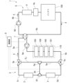
- 1 is a system configuration diagram showing a schematic configuration of a thermal management system according to an embodiment of the present invention
- 4 is a schematic diagram showing how a heat management heat medium is guided by a drive system circulation guide portion provided in the heat management system according to one embodiment of the present invention.
- FIG. 4 is a schematic diagram showing how a heat management heat medium is guided by a drive system circulation guide portion provided in the heat management system according to one embodiment of the present invention.
- FIG. 4 is a schematic diagram showing how a heat management heat medium is guided by a drive system circulation guide portion provided in the heat management system according to one embodiment of the present invention.
- FIG. 1 is a schematic configuration diagram of a vehicle equipped with a thermal management system according to an embodiment of the present invention
- 1 is a system configuration diagram showing a schematic configuration of a thermal management system according to an embodiment of the present invention
- 4 is a schematic diagram showing how a heat
- FIG. 4 is a schematic diagram showing how a heat management heat medium is guided by a drive system circulation guide portion provided in the heat management system according to one embodiment of the present invention.
- FIG. 1 is a system configuration diagram showing a schematic configuration of a first example of an in-vehicle air conditioning system
- FIG. 2 is a system configuration diagram showing a schematic configuration of a second example of an in-vehicle air conditioning system.
- 11 is a schematic diagram showing a modified example of a drive system circulation guide portion provided in the thermal management system according to the embodiment of the present invention.
- FIG. 11 is a schematic diagram showing a modified example of a drive system circulation guide portion provided in the thermal management system according to the embodiment of the present invention.
- FIG. 1 is a system configuration diagram showing a schematic configuration of a first example of an in-vehicle air conditioning system
- FIG. 2 is a system configuration diagram showing a schematic configuration of a second example of an in-vehicle air conditioning system.
- 11 is a schematic diagram showing
- FIG. 11 is a schematic diagram showing a modified example of a drive system circulation guide portion provided in the thermal management system according to the embodiment of the present invention.
- FIG. 11 is a schematic diagram showing a modified example of a drive system circulation guide portion provided in the thermal management system according to the embodiment of the present invention.
- FIG. 11 is a schematic diagram showing a modified example of a drive system circulation guide portion provided in the thermal management system according to the embodiment of the present invention.
- FIG. 1 is a schematic diagram of a vehicle 100 equipped with a thermal management system 1 according to this embodiment.
- the vehicle 100 is, for example, an electric vehicle.
- the vehicle 100 may also be a so-called hybrid vehicle equipped with both an internal combustion engine and a traction motor.
- the vehicle 100 is equipped with a traction motor 101, an inverter 102, an on-board charger 103, a DC/DC converter 104, and a battery 105 in addition to the thermal management system 1.
- the vehicle 100 is also equipped with an in-vehicle air conditioning system 20 as shown in FIG. 1.
- the traction motor 101 is a motor that generates power to drive the vehicle 100. This traction motor 101 generates rotational power from power supplied from the battery 105 via the inverter 102.
- the inverter 102 is disposed between the traction motor 101 and the battery 105 via a conductive path, and performs power conversion.
- the inverter 102 converts the DC power supplied from the battery 105 into AC power and supplies it to the traction motor 101.
- the inverter 102 also converts the AC regenerative power supplied from the traction motor 101 into DC power and supplies it to the battery 105.
- the on-board charger 103 generates DC power of a predetermined voltage from an external power system.
- the on-board charger 103 also inputs the generated DC power to the DC/DC converter 104.
- the DC/DC converter 104 is connected to the on-board charger 103 and the battery 105.
- This DC/DC converter 104 has a boost circuit that converts the DC power of a predetermined voltage input from the on-board charger 103 into DC power of a higher voltage (e.g., 400 volts), and supplies (charges) the boosted DC power to the battery 105.
- the DC/DC converter 104 also has a step-down circuit that converts the DC power charged in the battery 105 into DC power of a lower voltage (e.g., 12 volts), and supplies the stepped-down DC power as an operating power source for the in-vehicle air conditioning system 20 and the control unit 8 described below.
- a lower voltage e.g. 12 volts
- the battery 105 is a secondary battery that can be charged and discharged.
- the battery 105 stores the power input from the DC/DC converter 104.
- the battery 105 is not particularly limited, but may be, for example, a lithium ion battery using a liquid electrolyte.
- the battery 105 may also be, for example, a semi-solid battery using a gel electrolyte or an all-solid-state battery using a solid electrolyte.
- the battery 105 inputs the stored DC power to the inverter 102.
- the battery 105 can also store regenerated power input from a regenerative device (not shown) that processes the power regenerated during regenerative operation of the inverter 102 or the traction motor 101.
- FIG. 2 is a system configuration diagram showing the schematic configuration of the thermal management system 1 of this embodiment.
- the thermal management system 1 of this embodiment is a system that performs thermal management of the driving motor 101 and the like using a thermal management heat medium X such as so-called antifreeze.
- the thermal management system 1 of this embodiment includes an outside air heat exchanger 2, a first internal heat exchanger 3 (internal heat exchanger), a second internal heat exchanger 4 (internal heat exchanger), a drive system circulation guide unit 5 (circulation guide unit), a battery system circulation guide unit 6, a switching valve 7, and a control unit 8.
- the outdoor air heat exchanger 2 is a heat exchanger that exchanges heat between outdoor air and the heat management heat medium X. For example, when the heat management heat medium X has a higher temperature than the outdoor air, it dissipates heat to the outdoor air in the outdoor air heat exchanger 2. Also, when the heat management heat medium X has a lower temperature than the outdoor air, it can absorb heat from the outdoor air in the outdoor air heat exchanger 2.
- Such an outdoor air heat exchanger 2 is disposed midway along the outdoor air heat exchanger installation flow path 5i (described later) provided in the drive system circulation guide section 5.
- the first internal heat exchanger 3 is a heat exchanger that transfers heat from the compressible heat medium used in the vehicle air conditioning system 20 to the heat management heat medium X.
- the heat medium used in the vehicle air conditioning system 20 will be referred to as the air conditioning heat medium Y (see Figures 7 and 8).
- the air-conditioning heat medium Y is a heat medium different from the heat management heat medium X, and is an internal vehicle heat medium (another heat medium) contained in the vehicle 100.
- the heat management heat medium X releases heat to the air-conditioning heat medium Y in the first internal heat exchanger 3.
- the air-conditioning heat medium Y absorbs heat from the heat management heat medium X in the first internal heat exchanger 3.
- Such a first internal heat exchanger 3 is disposed in the middle of the first internal heat exchanger installation flow path 5d (described later) provided in the drive system circulation guide section 5.
- the second internal heat exchanger 4 is a heat exchanger separate from the first internal heat exchanger 3. Like the first internal heat exchanger 3, the second internal heat exchanger 4 is a heat exchanger that dissipates heat from the air-conditioning heat medium Y to the heat management heat medium X.
- the heat management heat medium X dissipates heat to the air-conditioning heat medium Y in the second internal heat exchanger 4.
- the air-conditioning heat medium Y absorbs heat from the heat management heat medium X in the second internal heat exchanger 4.
- Such a second internal heat exchanger 4 is disposed midway in the switching valve downstream flow path 6b, which is described later and which is provided in the battery system circulation guide section 6.
- the drive system circulation guidance unit 5 guides the heat management medium X to circulate through the heat management medium 110, which includes the driving motor 101, the inverter 102, the on-board charger 103, and the DC/DC converter 104 as thermally managed objects 110.
- the thermally managed objects 110 to be thermally managed by the drive system circulation guidance unit 5 are preselected from the group of devices constituting the vehicle 100, such as the driving motor 101, the inverter 102, the on-board charger 103, and the DC/DC converter 104, to which the heat management medium X is supplied (liquid-cooled devices).
- the vehicle 100 is equipped with a regenerative device or an internal combustion engine (neither of which is shown) that processes the power regenerated during regenerative operation of the driving motor 101, these may be included in the thermally managed objects 110.
- the drive system circulation guide unit 5 includes a switching valve upstream flow path 5a, a switching valve downstream flow path 5b, an upstream three-way valve 5c (flow path selection unit), a first internal heat exchanger installation flow path 5d, a first internal heat exchanger bypass flow path 5e, a first branching section 5f, a second branching section 5g, an intermediate flow path 5h, an outdoor air heat exchanger installation flow path 5i, an outdoor air heat exchanger bypass flow path 5j, a downstream three-way valve 5k (flow path selection unit), and a pump 5m.
- the switching valve upstream flow passage 5a is a flow passage located upstream of the switching valve 7 in the flow direction of the heat management heat medium X in the drive system circulation guide section 5.
- the downstream end of the switching valve upstream flow passage 5a is connected to the upstream side of the switching valve 7 in the flow direction of the heat management heat medium X.
- the upstream end of this switching valve upstream flow passage 5a is connected to the downstream three-way valve 5k.
- the switching valve downstream flow passage 5b is a flow passage located downstream of the switching valve 7 in the flow direction of the heat management heat medium X in the drive system circulation guide section 5.
- the upstream end of the switching valve downstream flow passage 5b is connected to the downstream side of the switching valve 7 in the flow direction of the heat management heat medium X.
- the downstream end of this switching valve downstream flow passage 5b is connected to the upstream three-way valve 5c.
- Pump 5m is disposed midway through flow path 5b downstream of the switching valve, and drives heat management medium X. More specifically, pump 5m is disposed upstream of the thermal management target 110.
- the thermal management subject 110 is disposed in the middle of the switching valve downstream flow path 5b.
- the temperature of the thermal management subject 110 which includes the traction motor 101, inverter 102, on-board charger 103, and DC/DC converter 104, is adjusted by exchanging heat with the thermal management heat medium X in the switching valve downstream flow path 5b.
- the traction motor 101, inverter 102, on-board charger 103, and DC/DC converter 104 are arranged in the flow direction of the heat management heat medium X in order of relatively low rated temperature.
- the on-board charger 103, DC/DC converter 104, inverter 102, and traction motor 101 are arranged in this order.
- the downstream end of the switching valve upstream flow path 5a and the upstream end of the switching valve downstream flow path 5b can be directly connected via a switching valve 7.
- the switching valve 7 can be controlled by a control unit 8.
- the switching valve upstream flow path 5a and the switching valve downstream flow path 5b are directly connected, meaning that the switching valve upstream flow path 5a and the switching valve downstream flow path 5b are connected by the shortest flow path with only the switching valve 7 interposed therebetween.
- the switching valve upstream flow path 5a and the switching valve downstream flow path 5b can be connected to the battery system circulation guide section 6 via the switching valve 7 (see FIG. 2).
- the switching valve upstream flow path 5a and the switching valve downstream flow path 5b can be connected to the battery system circulation guide section 6, via the switching valve 7 (see FIG. 2).
- the heat management heat medium X is supplied from the switching valve upstream flow path 5a to the battery system circulation guide section 6, and the heat management heat medium X that has passed through the battery system circulation guide section 6 is supplied to the switching valve downstream flow path 5b.
- the upstream three-way valve 5c is a three-way valve connected to the downstream end of the switching valve downstream flow path 5b, the upstream end of the first internal heat exchanger installation flow path 5d, and the upstream end of the first internal heat exchanger bypass flow path 5e.
- the upstream three-way valve 5c can be controlled by the control unit 8.
- This upstream three-way valve 5c can switch the connection state between the switching valve downstream flow path 5b, the first internal heat exchanger installation flow path 5d, and the first internal heat exchanger bypass flow path 5e between a state in which the heat management heat medium X supplied from the switching valve downstream flow path 5b flows into the first internal heat exchanger installation flow path 5d, and a state in which the heat management heat medium X supplied from the switching valve downstream flow path 5b flows into the first internal heat exchanger bypass flow path 5e.
- the first internal heat exchanger installation flow path 5d has an upstream end connected to the upstream three-way valve 5c and a downstream end connected to the first branch section 5f.
- the first internal heat exchanger installation flow path 5d is a flow path in which the first internal heat exchanger 3 is provided in the middle. In other words, the heat management heat medium X guided to the first internal heat exchanger installation flow path 5d exchanges heat with the air conditioning heat medium Y in the first internal heat exchanger 3.
- the first internal heat exchanger bypass flow path 5e has an upstream end connected to the upstream three-way valve 5c and a downstream end connected to the second branch section 5g.
- the first internal heat exchanger bypass flow path 5e is a flow path for guiding the heat management heat medium X so as to bypass the first internal heat exchanger 3.
- the heat management heat medium X guided to the first internal heat exchanger bypass flow path 5e passes through without exchanging heat with the air-conditioning heat medium Y.
- the first branch 5f is a hollow branch that connects the downstream end of the first internal heat exchanger installation flow path 5d, the upstream end of the outside air heat exchanger installation flow path 5i, and one end of the intermediate flow path 5h.
- the heat management heat medium X supplied from the first internal heat exchanger installation flow path 5d to the first branch 5f is guided to either the outside air heat exchanger installation flow path 5i or the intermediate flow path 5h based on the state of the downstream three-way valve 5k.
- the second branch 5g is a hollow branch that connects the downstream end of the first internal heat exchanger bypass flow path 5e, the upstream end of the outdoor air heat exchanger bypass flow path 5j, and the other end of the intermediate flow path 5h.
- the heat management heat medium X supplied to the second branch 5g is guided to either the outdoor air heat exchanger bypass flow path 5j or the intermediate flow path 5h.
- the intermediate flow passage 5h is a flow passage that connects the first branch portion 5f and the second branch portion 5g. One end of the intermediate flow passage 5h is connected to the first branch portion 5f, and the other end is connected to the second branch portion 5g. Based on the state of the upstream three-way valve 5c and the downstream three-way valve 5k, the intermediate flow passage 5h passes the heat management heat medium X in either the direction from the first branch portion 5f to the second branch portion 5g, or the direction from the second branch portion 5g to the first branch portion 5f.
- the upstream end of the outdoor air heat exchanger installation flow path 5i is connected to the first branch 5f, and the downstream end is connected to the downstream three-way valve 5k.
- the outdoor air heat exchanger installation flow path 5i is a flow path in which the outdoor air heat exchanger 2 is provided in the middle. In other words, the heat management heat medium X guided to the outdoor air heat exchanger installation flow path 5i exchanges heat with the outdoor air in the outdoor air heat exchanger 2.
- the outdoor air heat exchanger bypass flow path 5j has an upstream end connected to the second branch 5g and a downstream end connected to the downstream three-way valve 5k.
- the outdoor air heat exchanger bypass flow path 5j is a flow path for passing the heat management heat medium X so as to bypass the outdoor air heat exchanger 2. In other words, the heat management heat medium X guided to the outdoor air heat exchanger bypass flow path 5j passes through without exchanging heat with the outdoor air.
- the downstream three-way valve 5k is a three-way valve connected to the downstream end of the outdoor air heat exchanger installation flow path 5i, the downstream end of the outdoor air heat exchanger bypass flow path 5j, and the upstream end of the switching valve upstream flow path 5a.
- the downstream three-way valve 5k can be controlled by the control unit 8.
- This downstream three-way valve 5k can switch the connection state between the outdoor air heat exchanger installation flow path 5i, the outdoor air heat exchanger bypass flow path 5j, and the switching valve upstream flow path 5a between a state in which the heat management heat medium X supplied from the outdoor air heat exchanger installation flow path 5i flows into the switching valve upstream flow path 5a and blocks the downstream end of the outdoor air heat exchanger bypass flow path 5j, and a state in which the heat management heat medium X supplied from the outdoor air heat exchanger bypass flow path 5j flows into the switching valve upstream flow path 5a and blocks the outdoor air heat exchanger installation flow path 5i.
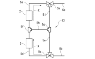
- Figures 3 to 6 are schematic diagrams showing how the heat management medium X is guided from the switching valve downstream flow path 5b to the switching valve upstream flow path 5a via the first internal heat exchanger installation flow path 5d, the first internal heat exchanger bypass flow path 5e, the intermediate flow path 5h, the outside air heat exchanger installation flow path 5i, or the outside air heat exchanger bypass flow path 5j.
- the upstream three-way valve 5c connects the switching valve downstream flow path 5b, the first internal heat exchanger installation flow path 5d, and the first internal heat exchanger bypass flow path 5e in a state in which the heat management heat medium X supplied from the switching valve downstream flow path 5b flows into the first internal heat exchanger bypass flow path 5e.
- the downstream three-way valve 5k connects the outdoor air heat exchanger installation flow path 5i, the outdoor air heat exchanger bypass flow path 5j, and the switching valve upstream flow path 5a in a state in which the heat management heat medium X supplied from the outdoor air heat exchanger installation flow path 5i flows into the switching valve upstream flow path 5a while blocking the downstream end of the outdoor air heat exchanger bypass flow path 5j.
- the heat management heat medium X supplied from the switching valve downstream flow path 5b to the upstream three-way valve 5c is guided in this order through the first internal heat exchanger bypass flow path 5e, the intermediate flow path 5h, and the outdoor air heat exchanger installation flow path 5i, and is supplied from the downstream three-way valve 5k to the switching valve upstream flow path 5a.
- the heat management heat medium X is heat exchanged only in the outdoor air heat exchanger 2 out of the outdoor air heat exchanger 2 and the first internal heat exchanger 3.
- the flow path formed by connecting the first internal heat exchanger bypass flow path 5e, the intermediate flow path 5h, and the external air heat exchanger installation flow path 5i shown in FIG. 3 is called the external air heat exchange flow path 10.
- the drive system circulation guide unit 5 has an external air heat exchange flow path 10 (first flow path) that allows the heat management heat medium X to pass only through the external air heat exchanger 2 of the external air heat exchanger 2 and the first internal heat exchanger 3.
- the upstream three-way valve 5c connects the switching valve downstream flow path 5b, the first internal heat exchanger installation flow path 5d, and the first internal heat exchanger bypass flow path 5e in a state in which the heat management heat medium X supplied from the switching valve downstream flow path 5b flows into the first internal heat exchanger installation flow path 5d.
- the downstream three-way valve 5k connects the outdoor air heat exchanger installation flow path 5i, the outdoor air heat exchanger bypass flow path 5j, and the switching valve upstream flow path 5a in a state in which the heat management heat medium X supplied from the outdoor air heat exchanger bypass flow path 5j flows into the switching valve upstream flow path 5a while blocking the outdoor air heat exchanger installation flow path 5i.
- the heat management heat medium X discharged from the upstream three-way valve 5c is guided in this order to the first internal heat exchanger installation flow path 5d, the intermediate flow path 5h, and the outside air heat exchanger bypass flow path 5j, and is supplied to the switching valve upstream flow path 5a from the downstream three-way valve 5k.
- the heat management heat medium X is heat exchanged only in the first internal heat exchanger 3 out of the outside air heat exchanger 2 and the first internal heat exchanger 3.
- the flow path formed by connecting the first internal heat exchanger installation flow path 5d, the intermediate flow path 5h, and the outdoor air heat exchanger bypass flow path 5j shown in Figure 4 is called the air conditioning heat medium heat exchange flow path 11.
- the drive system circulation guide unit 5 has an air conditioning heat medium heat exchange flow path 11 (second flow path) that allows the heat management heat medium X to pass only through the first internal heat exchanger 3 out of the outdoor air heat exchanger 2 and the first internal heat exchanger 3.
- the upstream three-way valve 5c connects the switching valve downstream flow path 5b, the first internal heat exchanger installation flow path 5d, and the first internal heat exchanger bypass flow path 5e in a state in which the heat management heat medium X supplied from the switching valve downstream flow path 5b flows into the first internal heat exchanger bypass flow path 5e.
- the downstream three-way valve 5k connects the outdoor air heat exchanger installation flow path 5i, the outdoor air heat exchanger bypass flow path 5j, and the switching valve upstream flow path 5a in a state in which the heat management heat medium X supplied from the outdoor air heat exchanger bypass flow path 5j flows into the switching valve upstream flow path 5a while blocking the outdoor air heat exchanger installation flow path 5i.
- the heat management medium X that has passed through the upstream three-way valve 5c is guided in this order to the first internal heat exchanger bypass flow path 5e and the outside air heat exchanger bypass flow path 5j, and is supplied to the switching valve upstream flow path 5a from the downstream three-way valve 5k.
- the heat management medium X is guided avoiding the outside air heat exchanger 2 and the first internal heat exchanger 3.
- the flow path formed by connecting the first internal heat exchanger bypass flow path 5e and the outside air heat exchanger bypass flow path 5j shown in FIG. 5 is called the heat exchanger bypass flow path 12.
- the drive system circulation guide unit 5 has a heat exchanger bypass flow path 12 (third flow path) that guides the heat management heat medium X avoiding the outside air heat exchanger 2 and the first internal heat exchanger 3.
- the upstream three-way valve 5c connects the switching valve downstream flow path 5b, the first internal heat exchanger installation flow path 5d, and the first internal heat exchanger bypass flow path 5e in a state in which the heat management heat medium X supplied from the switching valve downstream flow path 5b flows into the first internal heat exchanger installation flow path 5d.
- the downstream three-way valve 5k connects the outdoor air heat exchanger installation flow path 5i, the outdoor air heat exchanger bypass flow path 5j, and the switching valve upstream flow path 5a in a state in which the heat management heat medium X supplied from the outdoor air heat exchanger installation flow path 5i flows into the switching valve upstream flow path 5a while blocking the downstream end of the outdoor air heat exchanger bypass flow path 5j.
- the heat management heat medium X discharged from the upstream three-way valve 5c is guided in this order to the first internal heat exchanger installation flow path 5d and the outside air heat exchanger installation flow path 5i, and is supplied to the switching valve upstream flow path 5a from the downstream three-way valve 5k.
- the heat management heat medium X is guided in this order to the first internal heat exchanger 3 and the outside air heat exchanger 2.
- the heat management heat medium X is heat exchanged in both the first internal heat exchanger 3 and the outside air heat exchanger 2.
- the flow path formed by connecting the first internal heat exchanger installation flow path 5d and the outside air heat exchanger installation flow path 5i shown in FIG. 6 is called the serial heat exchange flow path 13.
- the drive system circulation guide unit 5 has a serial heat exchange flow path 13 (fourth flow path) that guides the heat management heat medium X to the first internal heat exchanger 3 and then the outside air heat exchanger 2 in that order.
- the heat management medium X is selectively guided to any one of the outdoor air heat exchange flow path 10, the air conditioning heat medium heat exchange flow path 11, the heat exchanger bypass flow path 12, and the serial heat exchange flow path 13 via the upstream three-way valve 5c and downstream three-way valve 5k controlled by the control unit 8.
- the upstream three-way valve 5c and the downstream three-way valve 5k function as a flow path selection unit.
- the flow path selection unit is described as a switching valve that switches the flow direction of the heat management medium X, but the flow path selection unit may be provided with a variable flow rate valve that can control the distribution rate of the heat management medium X to the outdoor air heat exchange flow path 10, the air conditioning heat medium heat exchange flow path 11, the heat exchanger bypass flow path 12, and the serial heat exchange flow path 13, for example.
- the battery system circulation guidance unit 6 manages the temperature of the battery 105. For example, when the temperature of the battery 105 is higher than a predetermined operating temperature range, the battery system circulation guidance unit 6 cools the battery 105. On the other hand, when the temperature of the battery 105 is lower than the predetermined operating temperature range, the battery system circulation guidance unit 6 heats the battery 105.
- This battery system circulation guidance unit 6 includes a switching valve upstream flow path 6a, a switching valve downstream flow path 6b, a heater 6c, and a pump 6d.
- the switching valve upstream flow path 6a is a flow path located upstream of the switching valve 7 in the flow direction of the heat management heat medium X in the battery system circulation guide section 6.
- the downstream end of the switching valve upstream flow path 6a is connected to the switching valve 7.
- the upstream end of the switching valve upstream flow path 6a is connected to the heater 6c.
- a battery 105 is disposed midway along the switching valve upstream flow path 6a.
- the switching valve downstream flow path 6b is a flow path located downstream of the switching valve 7 in the flow direction of the heat management heat medium X in the battery system circulation guide section 6.
- the upstream end of the switching valve downstream flow path 6b is connected to the switching valve 7.
- the downstream end of the switching valve downstream flow path 6b is connected to the heater 6c.
- a pump 6d and a second internal heat exchanger 4 are arranged in this order in the flow direction of the heat management heat medium X in the middle of the flow path 6b downstream of the switching valve.
- the downstream end of the switching valve upstream flow path 6a and the upstream end of the switching valve downstream flow path 6b can be directly connected via the switching valve 7.
- the switching valve upstream flow path 6a and the switching valve downstream flow path 6b are directly connected, which means that the switching valve upstream flow path 6a and the switching valve downstream flow path 6b are connected by the shortest route with only the switching valve 7 intervening.
- the switching valve upstream flow path 6a can be connected to the switching valve downstream flow path 5b via the switching valve 7. Further, the switching valve downstream flow path 6b can be connected to the switching valve upstream flow path 5a via the switching valve 7 (see FIG. 2).
- the switching valve upstream flow path 6a and the switching valve downstream flow path 6b can be connected to the switching valve downstream flow path 5b and the switching valve upstream flow path 5a, the heat management heat medium X is supplied from the switching valve upstream flow path 5a to the switching valve downstream flow path 6b, and the heat management heat medium X is supplied from the switching valve upstream flow path 6a to the switching valve downstream flow path 5b.
- the heater 6c is an electric heater that converts the DC power stored in the battery 105 into thermal energy to heat the heat management heat medium X, and in this embodiment is, for example, an electric water heater equipped with a PTC heater.
- the heater 6c is connected to the downstream end of the switching valve downstream flow path 6b and is connected to the upstream end of the switching valve upstream flow path 6a. This heater 6c heats the heat management heat medium X flowing through the switching valve downstream flow path 6b as necessary.
- the heater 6c is also connected to the control unit 8 and is controlled by the control unit 8.
- the pump 6d is disposed midway through the flow path 6b downstream of the switching valve, and causes the supplied heat management heat medium X to flow in the battery system circulation guide section 6. More specifically, the pump 6d is disposed downstream of the switching valve 7 and upstream of the second internal heat exchanger 4 in the flow direction of the heat management heat medium X in the battery system circulation guide section 6.
- the switching valve 7 is connected to the control unit 8 and is controlled by the control unit 8.
- the switching valve 7 switches the connection state between the drive system circulation guide unit 5 and the battery system circulation guide unit 6 between a series connection state and a non-connection state.
- the series connection state is a connection state in which the drive system circulation guide section 5 and the battery system circulation guide section 6 are connected in series so that the heat management heat medium X can flow in and out of each other.
- the downstream end of the switching valve upstream side flow path 5a is connected to the upstream end of the switching valve downstream side flow path 6b.
- the downstream end of the switching valve downstream side flow path 5b is connected to the upstream end of the switching valve upstream side flow path 6a.
- the non-connected state is a state in which the upstream flow path 5a of the switching valve and the downstream flow path 5b of the switching valve of the drive system circulation guide section 5 are directly connected, and the upstream flow path 6a of the switching valve and the downstream flow path 6b of the switching valve of the battery system circulation guide section 6 are directly connected, and in this state, the heat management heat medium X cannot flow in or out between the drive system circulation guide section 5 and the battery system circulation guide section 6.
- the control unit 8 controls the upstream three-way valve 5c, the downstream three-way valve 5k, and the switching valve 7. By controlling the upstream three-way valve 5c and the downstream three-way valve 5k, the control unit 8 selects a flow path for guiding the heat management heat medium X from among the outdoor air heat exchange flow path 10, the air conditioning heat medium heat exchange flow path 11, the heat exchanger bypass flow path 12, and the serial heat exchange flow path 13.
- the control unit 8 also controls the switching valve 7 to switch the connection state between the drive system circulation guide unit 5 and the battery system circulation guide unit 6 between a serial connection state and a non-connection state.
- the control unit 8 may also control the pumps 5m and 6d.
- the vehicle 100 also includes an outside air temperature sensor, an interior temperature sensor, a battery temperature sensor, and a heat management heat medium temperature sensor, none of which are shown.
- the control unit 8 is connected to these sensors. That is, the control unit 8 receives a signal indicating the outside air temperature from the outside air temperature sensor, a signal indicating the interior air temperature of the vehicle 100 from the interior temperature sensor, a signal indicating the temperature of the battery 105 from the battery temperature sensor, and a signal indicating the heat management heat medium temperature from the heat management heat medium temperature sensor.
- the control unit 8 also receives a signal indicating the operating state of the interior air conditioning system 20.
- the control unit 8 may receive an equipment status signal indicating the status of equipment installed in the vehicle 100.
- the control unit 8 controls the upstream three-way valve 5c and the downstream three-way valve 5k so that the heat management medium X is guided to the serial heat exchange flow path 13. In this case, the heat management medium X is heated by heat exchange with the outside air.
- the control unit 8 controls the upstream three-way valve 5c and the downstream three-way valve 5k so that the heat management heat medium X is guided to the air conditioning heat medium heat exchange flow path 11.
- the temperature at which no heat exhaust is required refers to a temperature at which the temperature of the heat management subject 110 is lower than the rated temperature and no heat exhaust is required.
- control unit 8 controls the upstream three-way valve 5c and the downstream three-way valve 5k so that the thermal management heat medium X is guided to the serial heat exchange flow path 13.
- the control unit 8 controls the upstream three-way valve 5c and the downstream three-way valve 5k so that the heat management heat medium X is guided to the heat exchanger bypass flow path 12.
- control unit 8 controls the upstream three-way valve 5c and the downstream three-way valve 5k so that the thermal management medium X is guided to the outside air heat exchange passage 10.
- the control unit 8 may estimate the future heat generation state of the heat management target 110 and control the upstream three-way valve 5c and the downstream three-way valve 5k based on the estimation result. Specifically, the control unit 8 estimates the future heat generation state of the heat management target 110 based on the device status signal indicating the state of the heat management target 110. When this estimated value exceeds, for example, the above-mentioned heat exhaust unnecessary temperature, the control unit 8 controls the upstream three-way valve 5c and the downstream three-way valve 5k so that the heat management heat medium X is guided to the outside air heat exchange flow path 10 even if the actual temperature of the heat management target 110 is the heat exhaust unnecessary temperature.
- control unit 8 controls the upstream three-way valve 5c and the downstream three-way valve 5k so that the heat management heat medium X is guided to the air conditioning heat medium heat exchange flow path 11 even if the actual temperature of the heat management target 110 exceeds the heat exhaust unnecessary temperature.
- the control unit 8 may also be an ECU (Electronic Control Unit) mounted on the vehicle 100. In such a case, the control unit 8 may control the in-vehicle air conditioning system 20 and the inverter 102.
- ECU Electronic Control Unit
- thermal management system 1 of this embodiment An example of the operation of the thermal management system 1 of this embodiment will be described. Here, we will explain the operation when the vehicle 100 is parked in a parking lot or the like, and the entire vehicle 100 is started after the temperature therein becomes approximately the same as the outside air temperature.
- the control unit 8 controls the switching valve 7 according to the battery system heat medium temperature, and sets the connection state between the drive system circulation guide unit 5 and the battery system circulation guide unit 6. At this time, for example, in winter when the temperature of the battery 105 is lower than the specified operating temperature range, the switching valve 7 is set so that the drive system circulation guide unit 5 and the battery system circulation guide unit 6 are in a disconnected state in order to quickly adjust the temperature of the battery 105.
- the heat management heat medium X is circulated independently in each of the drive system circulation guide section 5 and the battery system circulation guide section 6.
- the heat management heat medium X in the drive system circulation guide section 5 is circulated only in the drive system circulation guide section 5 by the pump 5m.
- the heat management heat medium X in the battery system circulation guide section 6 is circulated only in the battery system circulation guide section 6 by the pump 6d.
- the control unit 8 also controls the upstream three-way valve 5c and the downstream three-way valve 5k in response to a signal indicating the operating state of the vehicle air conditioning system 20. For example, when the vehicle 100 is started and the vehicle air conditioning system 20 is operating, the temperature of the air conditioning heat medium Y passing through the first internal heat exchanger 3 is reduced in pressure by an expansion valve, which will be described later, and becomes lower than the temperature of the outside air. Therefore, when the vehicle air conditioning system 20 is operating, the control unit 8 controls the upstream three-way valve 5c and the downstream three-way valve 5k so that the heat management heat medium X is guided to the serial heat exchange flow path 13.
- the heat management heat medium X dissipates heat to the air conditioning heat medium Y in the first internal heat exchanger 3, and then absorbs heat from the outside air in the outside air heat exchanger 2. Therefore, the temperature of the air conditioning heat medium Y and the heat management target 110 can be raised in a relatively short period of time after the vehicle 100 is started.
- the control unit 8 controls the upstream three-way valve 5c and the downstream three-way valve 5k so that the heat management heat medium X is guided to the air conditioning heat medium heat exchange flow path 11.
- the temperature of the air conditioning heat medium Y and the heat management target 110 can be raised in a relatively short period of time while preventing the heat management heat medium X from radiating heat in the outside air heat exchanger 2.
- the control unit 8 controls the upstream three-way valve 5c and the downstream three-way valve 5k so that the heat management medium X is again guided to the serial heat exchange flow path 13.
- the heat management medium X dissipates heat in the outside air heat exchanger 2 and the first internal heat exchanger 3, and the temperature of the heat management object 110 can be prevented from rising more than necessary.
- the heat of the heat management medium X can be effectively used in the vehicle air conditioning system 20. If the temperature of the heat management object 110 further increases, the amount of heat dissipated by the heat management medium X in the outside air heat exchanger 2 may be increased, for example, by forcibly blowing air to the outside air heat exchanger 2.
- the control unit 8 controls the upstream three-way valve 5c and the downstream three-way valve 5k so that the heat management heat medium X is guided to the heat exchanger bypass flow path 12.
- the heat management heat medium X does not dissipate heat in the outside air heat exchanger 2 and the first internal heat exchanger 3, and the temperature of the heat management target 110 can be raised in a relatively short period of time.
- the control unit 8 controls the upstream three-way valve 5c and the downstream three-way valve 5k so that the heat management heat medium X is guided to the outside air heat exchange flow path 10.
- the heat management heat medium X is dissipated in the outside air heat exchanger 2, and it is possible to prevent the temperature of the heat management target 110 from rising more than necessary. If the temperature of the heat management target 110 further rises, the amount of heat dissipated by the heat management heat medium X in the outside air heat exchanger 2 may be increased, for example, by forcibly blowing air to the outside air heat exchanger 2.
- the heat management heat medium X is circulated independently in the battery system circulation guide section 6.
- the heat management heat medium X circulated and guided by the battery system circulation guide section 6 is heated by passing through the battery 105 or the heater 6c.
- the control section 8 controls the switching valve 7 so that the drive system circulation guide section 5 and the battery system circulation guide section 6 are connected in series, and reduces or stops the supply of electricity to the heater 6c.
- the temperature of the battery 105 is raised in a relatively short period of time by the heat of the thermal management heat medium X, and power consumption by the heater 6c is reduced.
- the control unit 8 controls the switching valve 7 so that the drive system circulation guide unit 5 and the battery system circulation guide unit 6 are in a disconnected state. As a result, overheating of the battery 105 is avoided.
- the predetermined heat dissipation unnecessary temperature of the battery 105 is set to a temperature lower than the upper limit temperature of the predetermined operating temperature range of the battery 105.
- the control unit 8 forcibly operates the vehicle air conditioning system 20 to lower the temperature of the air conditioning heat medium Y circulating in the second internal heat exchanger 4.
- the temperature of the heat management heat medium X circulating in the battery system circulation guide unit 6 is lowered by absorbing heat from the air conditioning heat medium Y in the second internal heat exchanger 4.
- the temperature of the battery 105 can be lowered.
- Fig. 7 is a system configuration diagram showing the schematic configuration of a first example of the vehicle air conditioning system 20.
- the vehicle air conditioning system 20 uses an air conditioning heat medium Y to generate conditioned air to be supplied to the vehicle interior.
- the first example of the vehicle air conditioning system 20 (hereinafter referred to as vehicle air conditioning system 30) includes an external condenser 30a, a first circulation flow path 30b, an accumulator 30c, a compressor 30d, an internal heating condenser 30e, an expansion valve bypass flow path 30f, a second circulation flow path 30g, an evaporator 30h, an evaporator bypass flow path 30i, a plurality of expansion valves 30j, and a plurality of shutoff valves 30k.
- vehicle air conditioning system 30 includes an external condenser 30a, a first circulation flow path 30b, an accumulator 30c, a compressor 30d, an internal heating condenser 30e, an expansion valve bypass flow path 30f, a second circulation flow path 30g, an evaporator 30h, an evaporator bypass flow path 30i, a plurality of expansion valves 30j, and a plurality of shutoff valves 30k.
- the external condenser 30a is a heat exchanger that exchanges heat between the outside air and the air-conditioning heat medium Y. During heating, the external condenser 30a functions as an evaporator that evaporates the air-conditioning heat medium Y. During cooling, the external condenser 30a functions as a condenser that condenses the air-conditioning heat medium Y.
- the first circulation flow path 30b is a circulation flow path in which the external condenser 30a, the shutoff valve 30k1, the first internal heat exchanger 3, the accumulator 30c, the compressor 30d, the heating internal condenser 30e, and the expansion valve 30j1 are provided in this order along the way in the flow direction of the air-conditioning heat medium Y.
- the air-conditioning heat medium Y circulates through the first circulation flow path 30b.
- Compressor 30d is disposed downstream of accumulator 30c and upstream of internal heating condenser 30e in the flow direction of air-conditioning heat medium Y. Compressor 30d compresses air-conditioning heat medium Y and sends it downstream.
- the heating internal condenser 30e is located downstream of the compressor 30d and upstream of the expansion valve 30j1.
- the heating internal condenser 30e is a heat exchanger that uses the heat of the air-conditioning heat medium Y to heat the air to be supplied to the vehicle cabin.
- the heating internal condenser 30e functions as a condenser that condenses the air-conditioning heat medium Y.
- an expansion valve 30j1 is provided in the first circulation flow path 30b downstream of the internal heating condenser 30e and upstream of the external condenser 30a.
- This expansion valve 30j1 cools the air-conditioning heat medium Y in a liquid state condensed in the internal heating condenser 30e by reducing the pressure.
- the expansion valve bypass flow path 30f is connected to the first circulation flow path 30b so as to bypass this expansion valve 30j1.
- the first circulation flow path 30b branches off downstream of the heating internal condenser 30e, and a shutoff valve 30k2 is provided midway along the expansion valve bypass flow path 30f, which bypasses the expansion valve 30j1.
- the shutoff valve 30k2 closes the expansion valve bypass flow path 30f during heating and opens the expansion valve bypass flow path 30f during cooling.
- the junction point from the downstream end of the second circulation flow path 30g to the first circulation flow path 30b is provided in a section downstream of the shutoff valve 30k1 and the first internal heat exchanger 3, and upstream of the accumulator 30c, so that the air-conditioning heat medium Y does not pass through the first internal heat exchanger 3 during cooling.
- the junction point from the downstream end of the second circulation flow path 30g to the first circulation flow path 30b can also be set in a section downstream of the shutoff valve 30k1 and upstream of the first internal heat exchanger 3. In such a case, the air-conditioning heat medium Y passes through the first internal heat exchanger 3 in both heating and cooling.
- the evaporator 30h is a heat exchanger that uses the latent heat of the air-conditioning heat medium Y to cool the air to be supplied to the vehicle interior.
- the evaporator 30h is provided in the middle of the second circulation flow path 30g.
- the evaporator 30h functions as an evaporator that evaporates the liquid air-conditioning heat medium Y during cooling.
- the evaporator bypass flow path 30i is a branch flow path connected to the second circulation flow path 30g so as to bypass the evaporator 30h.
- an expansion valve 30j3 and a second internal heat exchanger 4 are provided in this order in the flow direction of the air-conditioning heat medium Y.
- the branch point from the second circulation flow path 30g to the evaporator bypass flow path 30i is provided in the section from the upstream end of the second circulation flow path 30g described above to the expansion valve 30j2.
- junction point from the downstream end of the evaporator bypass flow path 30i to the second circulation flow path 30g is provided in the section from the downstream side of the evaporator 30h to the junction point of the second circulation flow path 30g described above with the first circulation flow path 30b.
- the expansion valve 30j lowers the temperature of the air-conditioning heat medium Y by suddenly lowering the pressure of the air-conditioning heat medium Y.
- one expansion valve 30j1 is disposed in the first circulation flow path 30b downstream of the internal heating condenser 30e and upstream of the external condenser 30a.
- One expansion valve 30j2 is disposed in the second circulation flow path 30g upstream of the evaporator 30h.
- One expansion valve 30j3 is disposed in the evaporator bypass flow path 30i upstream of the second internal heat exchanger 4.
- Each expansion valve 30j is also capable of closing the flow path in which it is provided.
- Shut-off valve 30k is an on-off valve that opens and closes the provided flow path. As described above, shut-off valve 30k1 is disposed in first circulation flow path 30b downstream of external condenser 30a and upstream of first internal heat exchanger 3. Also, as described above, one shut-off valve 30k2 is disposed in expansion valve bypass flow path 30f.
- the expansion valve 30j1 provided in the first circulation flow path 30b opens the flow path
- the shutoff valve 30k1 opens the flow path
- the shutoff valve 30k2 provided in the expansion valve bypass flow path 30f closes the flow path.
- the shutoff valve 30k1 provided immediately before the first internal heat exchanger 3 closes the flow path
- the expansion valve 30j2 provided in the middle of the second circulation flow path 30g opens the flow path.
- the shutoff valve 30k1 provided immediately before the first internal heat exchanger 3 closes the flow path, and the expansion valve 30j3 provided in the evaporator bypass flow path 30i opens the flow path.
- the air-conditioning heat medium Y compressed by the compressor 30d is condensed in the heating internal condenser 30e, and then depressurized by the expansion valve 30j1 provided midway along the first circulation flow path 30b from the heating internal condenser 30e to the external condenser 30a.
- the air-conditioning heat medium Y which has become colder than the outside air temperature as a result of this decompression, absorbs heat from the outside air in the external condenser 30a and evaporates.
- the air-conditioning heat medium Y evaporated in the external condenser 30a is heated by receiving heat from the heat management heat medium X in the first internal heat exchanger 3 provided downstream of the external condenser 30a, and is then adiabatically compressed by the compressor 30d, and its temperature and pressure are increased.
- the air-conditioning heat medium Y that has passed through the external condenser 30a is heated by receiving heat from the heat management heat medium X in the first internal heat exchanger 3, and is then heated and pressurized in the compressor 30d.
- the air-conditioning heat medium Y heated in the first internal heat exchanger 3 is compressed in the compressor 30d, so the energy consumption required to heat the air-conditioning heat medium Y in the compressor 30d is reduced compared to when the air-conditioning heat medium Y is not heated in the first internal heat exchanger 3.
- the air-conditioning heat medium Y receives heat from the first internal heat exchanger 3, thereby improving the energy efficiency of the in-vehicle air-conditioning system 30.
- the air-conditioning heat medium Y is diverted from the first circulation flow path 30b to the second circulation flow path 30g downstream of the external condenser 30a, and is depressurized by an expansion valve 30j2 provided in a portion of the second circulation flow path 30g.
- the air-conditioning heat medium Y which has become colder than the outside air temperature as a result of this depressurization, is heated by heat exchange with the air (inside air) in the vehicle cabin in the evaporator 30h (cooling the air in the vehicle cabin) and evaporates.
- the air-conditioning heat medium Y is diverted from the second circulation flow path 30g to the evaporator bypass flow path 30i downstream of the external condenser 30a, and is depressurized by an expansion valve 30j3 provided in a portion of the evaporator bypass flow path 30i.
- the air-conditioning heat medium Y which has become colder than the outside air temperature due to this pressure reduction, absorbs heat from the heat management heat medium X in the battery system circulation guide section 6 in the second internal heat exchanger 4, thereby lowering the temperature of the heat management heat medium X.
- the air-conditioning heat medium Y in the second circulation flow path 30g via the evaporator 30h and the air-conditioning heat medium Y in the evaporator bypass flow path 30i via the second internal heat exchanger 4 are merged and pressurized by the compressor 30d.
- the air-conditioning heat medium Y receives heat from the second internal heat exchanger 4, so that the temperature of the battery 105 can be appropriately managed while adjusting the air in the vehicle cabin to an appropriate temperature.
- FIG. 8 is a system configuration diagram showing the schematic configuration of a second example of the vehicle air conditioning system 20.
- the second example of the vehicle air conditioning system 20 (hereinafter referred to as the vehicle air conditioning system 40) includes an external condenser 40a, a first circulation flow path 40b, an accumulator 40c, a compressor 40d, an internal condenser for heating 40e, an external condenser bypass flow path 40f, a second circulation flow path 40g, an evaporator 40h, an evaporator bypass flow path 40i, a plurality of expansion valves 40j, a plurality of three-way valves 40k, and a connection flow path for cooling 40m.
- the vehicle air conditioning system 40 includes an external condenser 40a, a first circulation flow path 40b, an accumulator 40c, a compressor 40d, an internal condenser for heating 40e, an external condenser bypass flow path 40f, a second circulation flow path 40g, an evaporator 40h, an e
- the external condenser 40a is a heat exchanger that exchanges heat between the outside air and the air-conditioning heat medium Y. During heating, the external condenser 40a functions as an evaporator that evaporates the air-conditioning heat medium Y. During cooling, the external condenser 40a functions as a condenser that condenses the air-conditioning heat medium Y.
- the first circulation flow path 40b is a circulation flow path in which an external condenser 40a is provided midway.
- the external condenser 40a, the first three-way valve 40k1, the accumulator 40c, the compressor 40d, the second three-way valve 40k2, the internal heating condenser 40e, and the expansion valve 40j1 are arranged in this order in the flow direction of the air-conditioning heat medium Y.
- the external condenser 40a is a heat exchanger that exchanges heat between the outside air and the air-conditioning heat medium Y. During heating, the external condenser 40a functions as an evaporator that evaporates the air-conditioning heat medium Y. During cooling, the external condenser 40a functions as a condenser that condenses the air-conditioning heat medium Y.
- the first three-way valve 40k1 which is one of the three-way valves 40k, is arranged downstream of the external condenser 40a and upstream of the accumulator 40c. The upstream end of the second circulation flow path 40g, which will be described later, is also connected to this first three-way valve 40k1.
- the first three-way valve 40k1 is a control valve that can switch the direction of the air-conditioning heat medium Y supplied from the external condenser 40a between a direction toward the accumulator 40c of the first circulation flow path 40b and a direction toward the second circulation flow path 40g.
- the first three-way valve 40k1 guides the air-conditioning heat medium Y in the direction toward the accumulator 40c during heating, and guides the air-conditioning heat medium Y in the direction toward the second circulation flow path 40g during cooling.
- the compressor 40d is disposed downstream of the accumulator 40c and upstream of the second three-way valve 40k2 in the flow direction of the air-conditioning heat medium Y.
- the compressor 40d compresses the air-conditioning heat medium Y and sends it out downstream.
- the second three-way valve 40k2 which is one of the three-way valves 40k, is located downstream of the compressor 40d and upstream of the heating internal condenser 40e.
- the upstream end of the cooling connection flow path 40m which will be described later, is also connected to this second three-way valve 40k2.
- the second three-way valve 40k2 is a control valve that can switch the direction in which the air-conditioning heat medium Y is supplied between the direction toward the heating internal condenser 40e and the direction toward the cooling connection flow path 40m.
- the second three-way valve 40k2 allows the air-conditioning heat medium Y to flow in the direction toward the heating internal condenser 40e during heating, and allows the air-conditioning heat medium Y to flow in the direction toward the cooling connection flow path 40m during cooling.
- the heating internal condenser 40e is a heat exchanger that uses the heat of the air-conditioning heat medium Y to heat the air to be supplied to the vehicle cabin.
- the heating internal condenser 40e is disposed downstream of the second three-way valve 40k2 and upstream of the expansion valve 40j1.
- the heating internal condenser 40e functions as a condenser that condenses the air-conditioning heat medium Y.
- an expansion valve 40j1 is provided downstream of the internal heating condenser 40e and upstream of the external condenser 40a in the first circulation flow path 40b. This expansion valve 40j1 cools the air-conditioning heat medium Y in a liquid state condensed in the internal heating condenser 40e by reducing the pressure.
- the external condenser bypass flow path 40f is connected to the first circulation flow path 40b so as to bypass the external condenser 40a.
- the upstream end of the external condenser bypass flow path 40f is connected to the downstream side of the heating internal condenser 40e and the upstream side of the expansion valve 40j1 in the flow direction of the air-conditioning heat medium Y.
- An expansion valve 40j2 and a first internal heat exchanger 3 are provided in this order in the flow direction of the air-conditioning heat medium Y at a midpoint of the external condenser bypass flow path 40f.
- the cooling connection flow path 40m is provided to connect the second three-way valve 40k2 and the upstream portion of the external condenser 40a of the first circulation flow path 40b.
- the upstream end of the cooling connection flow path 40m is connected to the second three-way valve 40k2.
- the downstream end of the cooling connection flow path 40m is connected to the downstream side of the expansion valve 40j1 and the upstream side of the external condenser 40a in the flow direction of the air-conditioning heat medium Y.
- the second circulation flow path 40g is a branch flow path whose upstream and downstream ends are connected to the first circulation flow path 40b. As described above, the upstream end of the second circulation flow path 40g is connected to the first three-way valve 40k1. The downstream end of the second circulation flow path 40g is connected to the downstream side of the first three-way valve 40k1 of the first circulation flow path 40b and the upstream side of the accumulator 40c in the flow direction of the air-conditioning heat medium Y. An expansion valve 40j3 and an evaporator 40h are provided in this order in the middle of the second circulation flow path 40g in the flow direction of the air-conditioning heat medium Y.
- the evaporator 40h is a heat exchanger that uses the latent heat of the air-conditioning heat medium Y to cool the air to be supplied to the vehicle interior.
- the evaporator 40h is provided in the middle of the second circulation flow path 40g.
- the evaporator 40h functions as an evaporator that evaporates the liquid air-conditioning heat medium Y during cooling.
- the evaporator bypass flow path 40i is connected to the second circulation flow path 40g so as to bypass the evaporator 40h.
- the upstream end of the evaporator bypass flow path 40i is connected to the downstream side of the first three-way valve 40k1 of the first circulation flow path 40b and the upstream side of the expansion valve 40j3 of the second circulation flow path 40g in the flow direction of the air-conditioning heat medium Y.
- the downstream end of the evaporator bypass flow path 40i is connected to the downstream side of the first three-way valve 40k1 of the first circulation flow path 40b and the upstream side of the accumulator 40c in the flow direction of the air-conditioning heat medium Y.
- An expansion valve 40j4 and a second internal heat exchanger 4 are provided in this order in the middle of the evaporator bypass flow path 40i in the flow direction of the air-conditioning heat medium Y.
- the expansion valve 40j lowers the temperature of the air-conditioning heat medium Y by suddenly lowering the pressure of the air-conditioning heat medium Y.
- one expansion valve 40j1 is disposed in the first circulation flow path 40b downstream of the internal heating condenser 40e and upstream of the external condenser 40a.
- one expansion valve 40j2 is disposed midway through the external condenser bypass flow path 40f.
- One expansion valve 40j3 is disposed upstream of the evaporator 40h in the second circulation flow path 40g.
- One expansion valve 40j4 is provided midway through the evaporator bypass flow path 40i.
- Each expansion valve 40j is also capable of closing the flow path in which it is provided.
- the expansion valve 40j1 located upstream of the external condenser 40a and the expansion valve 40j2 provided in the external condenser bypass flow path 40f open the flow path.
- the first three-way valve 40k1 flows the air-conditioning heat medium Y supplied from the external condenser 40a in the direction toward the accumulator 40c.
- the second three-way valve 40k2 flows the air-conditioning heat medium Y in the direction toward the heating internal condenser 40e.
- the air-conditioning heat medium Y compressed by the compressor 40d is condensed in the heating internal condenser 40e, and then decompressed by the expansion valve 40j1 provided in the middle of the first circulation flow path 40b from the heating internal condenser 40e to the external condenser 40a, and becomes lower in temperature than the outside air temperature.
- the air-conditioning heat medium Y thus cooled is evaporated in the external condenser 40a and absorbs heat from the outside air.
- the air-conditioning heat medium Y is condensed in the internal heating condenser 40e, then diverted to the external condenser bypass flow path 40f, where it is depressurized by the expansion valve 40j2 provided in the middle of the external condenser bypass flow path 40f, and becomes lower in temperature than the outside air temperature.
- the air-conditioning heat medium Y which has been cooled by the expansion valve 40j2, absorbs heat from the heat management heat medium X in the first internal heat exchanger 3 provided downstream of the expansion valve 40j2, and is heated.
- the air-conditioning heat medium Y evaporated in the external condenser 40a merges with the air-conditioning heat medium Y heated in the first internal heat exchanger 3, and is then compressed by the compressor 30d, and is heated and pressurized.
- the air-conditioning heat medium Y heated in the first internal heat exchanger 3 is merged with the air-conditioning heat medium Y that has absorbed heat from the outside air in the external condenser 40a and is supplied to the compressor 40d, so the energy consumption required to heat the air-conditioning heat medium Y in the compressor 40d is reduced compared to when the air-conditioning heat medium Y is not heated in the first internal heat exchanger 3.
- the air-conditioning heat medium Y receives heat from the first internal heat exchanger 3, thereby improving the energy efficiency of the in-vehicle air-conditioning system 40.
- the first three-way valve 40k1 guides the air-conditioning heat medium Y supplied from the external condenser 40a to the second circulation flow path 40g. Furthermore, the second three-way valve 40k2 guides the air-conditioning heat medium Y to the cooling connection flow path 40m.
- the air-conditioning heat medium Y is diverted from the first circulation flow path 40b to the second circulation flow path 40g downstream of the external condenser 40a, and is depressurized by an expansion valve 40j3 provided in an intermediate portion of the second circulation flow path 40g.
- the air-conditioning heat medium Y which has become colder than the outside air temperature as a result of this pressure reduction, is heated (cools the air in the vehicle cabin) by heat exchange with the air in the vehicle cabin in the evaporator 40h, and is evaporated.
- the air-conditioning heat medium Y when the temperature of the battery 105 is to be lowered, the air-conditioning heat medium Y is diverted from the second circulation flow path 40g to the evaporator bypass flow path 40i, and is depressurized by an expansion valve 40j4 provided in an intermediate portion of the evaporator bypass flow path 40i.
- the air-conditioning heat medium Y which has become colder than the outside air temperature due to this pressure reduction, absorbs heat from the heat management heat medium X in the battery system circulation guide section 6 in the second internal heat exchanger 4, thereby lowering the temperature of the heat management heat medium X.
- the air-conditioning heat medium Y in the second circulation flow path 40g via the evaporator 40h is merged with the air-conditioning heat medium Y in the evaporator bypass flow path 40i via the second internal heat exchanger 4, and is then pressurized by the compressor 40d.
- the air-conditioning heat medium Y receives heat from the second internal heat exchanger 4, making it possible to appropriately manage the temperature of the battery 105 while adjusting the air in the vehicle cabin to an appropriate temperature.
- the thermal management system 1 of this embodiment as described above is mounted on a vehicle 100 and performs thermal management of a thermal management target 110 including a driving motor 101.
- the thermal management system 1 of this embodiment includes an outside air heat exchanger 2, a first internal heat exchanger 3, a drive system circulation guide unit 5, a second internal heat exchanger 4, and a battery system circulation guide unit 6.
- the outside air heat exchanger 2 exchanges heat between the outside air and the thermal management heat medium X.
- the first internal heat exchanger 3 and the second internal heat exchanger 4 exchange heat between the air conditioning heat medium Y, which is another heat medium included in the vehicle 100, and the thermal management heat medium X.
- the drive system circulation guide unit 5 guides the thermal management heat medium X to circulate through the thermal management target 110.
- the battery system circulation guide unit 6 guides the thermal management heat medium X to circulate through the battery 105.
- the drive system circulation guide section 5 includes an outside air heat exchange flow path 10, an air conditioning heat medium heat exchange flow path 11, a heat exchanger bypass flow path 12, a serial heat exchange flow path 13, an upstream three-way valve 5c, and a downstream three-way valve 5k.
- the outside air heat exchange flow path 10 passes the heat management heat medium X only through the outside air heat exchanger 2 of the outside air heat exchanger 2 and the first internal heat exchanger 3.
- the air conditioning heat medium heat exchange flow path 11 passes the heat management heat medium X only through the first internal heat exchanger 3 of the outside air heat exchanger 2 and the first internal heat exchanger 3.
- the heat exchanger bypass flow path 12 passes the heat management heat medium X while avoiding the outside air heat exchanger 2 and the first internal heat exchanger 3.
- the serial heat exchange flow path 13 passes the heat management heat medium X in the order of the first internal heat exchanger 3 and the outside air heat exchanger 2.
- the upstream three-way valve 5c and the downstream three-way valve 5k selectively guide the heat management heat medium X to one or more of the outdoor air heat exchange flow path 10, the air conditioning heat medium heat exchange flow path 11, the heat exchanger bypass flow path 12, and the serial heat exchange flow path 13.
- the thermal management system 1 of this embodiment can select to thermally manage the thermal management target 110 by passing the thermal management heat medium X only through the external air heat exchanger 2 of the external air heat exchanger 2 and the first internal heat exchanger 3, to thermally manage the thermal management target 110 and the battery 105 by passing the thermal management heat medium X only through the internal air heat exchanger of the external air heat exchanger 2 and the first internal heat exchanger 3, to thermally manage the thermal management target 110 and the battery 105 by passing the thermal management heat medium X through both the external air heat exchanger 2 and the first internal heat exchanger 3 connected in series, or to thermally manage the thermal management target 110 and the battery 105 by guiding the thermal management heat medium X while avoiding both the external air heat exchanger 2 and the first internal heat exchanger 3. Therefore, according to the thermal management system 1 of this embodiment, flexible and efficient thermal management can be realized with a simple structure in the thermal management system 1 mounted on the vehicle 100.
- the first internal heat exchanger 3 exchanges heat between the air-conditioning heat medium Y used in the vehicle air-conditioning system 20 and the heat management heat medium X.
- the heat recovered by the heat management heat medium X can be effectively used in the vehicle air-conditioning system 20. Therefore, the thermal management system 1 of this embodiment can improve the electric power consumption of an electric vehicle, for example.
- the thermal management system 1 of this embodiment also includes a control unit 8 that controls the upstream three-way valve 5c and the downstream three-way valve 5k.
- the control unit 8 controls the upstream three-way valve 5c and the downstream three-way valve 5k so that the thermal management heat medium X is guided to the serial heat exchange flow path 13.
- the thermal management heat medium X can absorb heat from the outside air by the outside air heat exchanger 2. This makes it possible to raise the temperature of the thermal management target 110 and the battery 105, for example, in a short period of time.
- control unit 8 controls the upstream three-way valve 5c and the downstream three-way valve 5k so that the thermal management heat medium X is guided to the air conditioning heat medium heat exchange passage 11 when the in-vehicle air conditioning system 20 is operating, the temperature of the thermal management heat medium X that has passed through the first internal heat exchanger 3 is higher than the temperature of the outside air, and the temperature of the thermal management object 110 and the battery 105 are at a temperature that does not require heat exhaust to the outside.
- the thermal management system 1 of this embodiment can prevent the heat recovered by the thermal management heat medium X from being released into the outside air when the temperature of the thermally managed object 110 and the battery 105 is such that heating is required. Therefore, for example, it is possible to raise the temperature of the thermally managed object 110 in a short period of time.
- the control unit 8 controls the upstream three-way valve 5c and the downstream three-way valve 5k so that the thermal management heat medium X is guided to the serial heat exchange flow path 13.
- the thermal management system 1 of this embodiment can dissipate heat from the thermal management heat medium X by the first internal heat exchanger 3 and the outside air heat exchanger 2. This makes it possible to prevent, for example, the thermal management subject 110 or the battery 105 from becoming hotter than their respective rated temperatures.
- the control unit 8 controls the upstream three-way valve 5c and the downstream three-way valve 5k so that the thermal management heat medium X is guided to the heat exchanger bypass flow path 12.
- the thermal management system 1 of this embodiment can prevent the thermal management heat medium X from dissipating heat into the outside air. Therefore, it can be used, for example, to increase the temperature (warm up) of the thermal management target 110 and the battery 105 in a relatively short time.
- the control unit 8 controls the upstream three-way valve 5c and the downstream three-way valve 5k so that the thermal management heat medium X is guided to the outside air heat exchange passage 10.
- the thermal management system 1 of this embodiment can dissipate heat from the thermal management heat medium X to the outside air in the outside air heat exchanger 2. This makes it possible to prevent, for example, the thermal management target 110 or the battery 105 from becoming hotter than their respective rated temperatures.
- the control unit 8 forcibly operates the compressor of the vehicle air conditioning system 20 and controls the upstream three-way valve 5c and the downstream three-way valve 5k so that the thermal management heat medium X is guided to the serial heat exchange flow path 13.
- the thermal management system 1 of this embodiment can dissipate heat from the thermal management heat medium X in the first internal heat exchanger 3, the second internal heat exchanger 4, and the outside air heat exchanger 2 even when the vehicle interior air conditioning system 20 is stopped. This makes it possible to prevent, for example, the thermal management target 110 or the battery 105 from becoming higher than necessary relative to their respective rated temperatures.
- the control unit 8 controls the switching valve 7 so that the drive system circulation guide unit 5 and the battery system circulation guide unit 6 are in a disconnected state. At this time, even if the vehicle air conditioning system 20 is stopped, the control unit 8 forcibly operates the compressor of the vehicle air conditioning system 20, and controls the thermal management heat medium X to dissipate heat through the second internal heat exchanger 4.
- control unit 8 may estimate the future heat generation state of the thermal management subject 110 and the battery 105, and control the upstream three-way valve 5c, the downstream three-way valve 5k, and the switching valve 7 based on this estimation result.
- Such a thermal management system 1 of this embodiment can improve the responsiveness of the flow path switching operation to changes in the state of the thermal management subject 110, and prevent overshooting or undershooting of the temperatures of the thermal management subject 110 and the battery 105.
- the thermal management system 1 is described as having a configuration including a drive system circulation guide unit 5, a battery system circulation guide unit 6, and a switching valve 7.
- the present invention is not limited to this.
- the present invention can also adopt a configuration that does not include a switching valve 7 when the battery 105 is configured with a so-called solid-state battery whose unnecessary heat exhaust temperature is approximately the same as that of the thermal management target 110.
- the flow path selection unit is described as having an upstream three-way valve 5c and a downstream three-way valve 5k.
- the present invention is not limited to this.
- the flow path selection unit may be configured to have an upstream three-way valve 5c and one four-way valve 50.
- the first internal heat exchanger bypass flow path 5e, the intermediate flow path 5h, the outside air heat exchanger installation flow path 5i, and the switching valve upstream flow path 5a are connected to the four-way valve 50.
- the first flow path, the second flow path, the third flow path, and the fourth flow path of the present invention can be formed by controlling the upstream three-way valve 5c and the four-way valve 50.
- the flow path selection unit can be configured to include an upstream three-way valve 5c and one five-way valve 51.
- the first internal heat exchanger installation flow path 5d, the first internal heat exchanger bypass flow path 5e, the outdoor air heat exchanger installation flow path 5i, and the outdoor air heat exchanger bypass flow path 5j are connected to the five-way valve 51.
- a branch section 52 is provided to connect the switching valve upstream flow path 5a, the outdoor air heat exchanger installation flow path 5i, and the outdoor air heat exchanger bypass flow path 5j.
- the first flow path, the second flow path, the third flow path, and the fourth flow path of the present invention can be formed by controlling the upstream three-way valve 5c and the five-way valve 51.
- the flow path selection unit it is possible to configure the flow path selection unit to include one six-way valve 53.
- the six-way valve 53 is connected to the upstream flow path 5a of the switching valve, the downstream flow path 5b of the switching valve, the upstream end and downstream end of the outdoor air heat exchanger installation flow path 5i, and the upstream end and downstream end of the first internal heat exchanger installation flow path 5d.
- the first flow path, the second flow path, the third flow path, and the fourth flow path of the present invention can be formed by controlling the six-way valve 53.
- the third flow path can be formed by the six-way valve 53 that directly connects the upstream flow path 5a of the switching valve and the downstream flow path 5b of the switching valve.
- the flow path selection unit it is possible to configure the flow path selection unit to have one four-way valve 54.
- the four-way valve 54 is connected to the switching valve downstream side flow path 5b, the first internal heat exchanger installation flow path 5d, the intermediate flow path 5h, and the outdoor air heat exchanger bypass flow path 5j.
- a branch section 55 is provided to connect the switching valve upstream side flow path 5a, the outdoor air heat exchanger installation flow path 5i, and the outdoor air heat exchanger bypass flow path 5j.
- the first flow path, second flow path, third flow path, and fourth flow path of the present invention can be formed by controlling the four-way valve 54.
- a thermal management system that is mounted on a vehicle and performs thermal management of a thermal management target including a driving motor, an outside air heat exchanger for exchanging heat between outside air and a heat management medium; an internal heat exchanger for exchanging heat between the vehicle internal heat medium, which is another heat medium contained in the vehicle, and the heat management heat medium; a circulation guide section that circulates and guides the heat management heat medium so that the heat management heat medium passes through the heat management object,
- the circulation guide portion is a first flow path through which the heat management heat medium passes only through the outside air heat exchanger out of the outside air heat exchanger and the internal heat exchanger; a second flow passage through which the heat management heat medium passes only through the internal heat exchanger out of the external air heat exchanger and the internal heat exchanger; a third flow path through which the heat management heat medium passes while avoiding the external air heat exchanger and the internal heat exchanger; a fourth flow path through which the heat management heat medium passes through the internal heat exchanger and the external air heat exchanger in this order; a flow path selection
- the vehicle interior heat transfer medium includes a compressible air conditioning heat transfer medium used in an in-vehicle air conditioning system, 2.
- Appendix 4 The thermal management system described in Appendix 3, characterized in that the control unit controls the flow path selection unit so that the thermal management heat medium is guided to the second flow path when the vehicle air conditioning system is operating, the temperature of the thermal management heat medium that has passed through the internal heat exchanger is higher than the temperature of the outside air, and the temperature of the thermal management object is a heat discharge non-required temperature that does not require heat discharge to the outside.
- Appendix 6 The thermal management system described in any one of appendices 3 to 5, characterized in that the control unit controls the flow path selection unit so that the heat management heat medium is guided to the third flow path when the vehicle air conditioning system is stopped, the temperature of the heat management heat medium that has passed through the thermal management object is higher than the temperature of the outside air, and the temperature of the thermal management object is a heat exhaust non-required temperature that does not require heat exhaust to the outside.
Landscapes
- Engineering & Computer Science (AREA)
- Life Sciences & Earth Sciences (AREA)
- Sustainable Development (AREA)
- Sustainable Energy (AREA)
- Power Engineering (AREA)
- Transportation (AREA)
- Mechanical Engineering (AREA)
- Air-Conditioning For Vehicles (AREA)
Priority Applications (3)
| Application Number | Priority Date | Filing Date | Title |
|---|---|---|---|
| JP2025533749A JPWO2025017810A1 (https=) | 2023-07-14 | 2023-07-14 | |
| PCT/JP2023/026146 WO2025017810A1 (ja) | 2023-07-14 | 2023-07-14 | 熱管理システム |
| CN202380099886.7A CN121419899A (zh) | 2023-07-14 | 2023-07-14 | 热管理系统 |
Applications Claiming Priority (1)
| Application Number | Priority Date | Filing Date | Title |
|---|---|---|---|
| PCT/JP2023/026146 WO2025017810A1 (ja) | 2023-07-14 | 2023-07-14 | 熱管理システム |
Publications (1)
| Publication Number | Publication Date |
|---|---|
| WO2025017810A1 true WO2025017810A1 (ja) | 2025-01-23 |
Family
ID=94281822
Family Applications (1)
| Application Number | Title | Priority Date | Filing Date |
|---|---|---|---|
| PCT/JP2023/026146 Pending WO2025017810A1 (ja) | 2023-07-14 | 2023-07-14 | 熱管理システム |
Country Status (3)
| Country | Link |
|---|---|
| JP (1) | JPWO2025017810A1 (https=) |
| CN (1) | CN121419899A (https=) |
| WO (1) | WO2025017810A1 (https=) |
Citations (2)
| Publication number | Priority date | Publication date | Assignee | Title |
|---|---|---|---|---|
| JP2019119369A (ja) * | 2018-01-09 | 2019-07-22 | 株式会社デンソー | 熱管理システム |
| JP2022043745A (ja) * | 2020-09-04 | 2022-03-16 | 日立Astemo株式会社 | 熱管理システム |
-
2023
- 2023-07-14 WO PCT/JP2023/026146 patent/WO2025017810A1/ja active Pending
- 2023-07-14 JP JP2025533749A patent/JPWO2025017810A1/ja active Pending
- 2023-07-14 CN CN202380099886.7A patent/CN121419899A/zh active Pending
Patent Citations (2)
| Publication number | Priority date | Publication date | Assignee | Title |
|---|---|---|---|---|
| JP2019119369A (ja) * | 2018-01-09 | 2019-07-22 | 株式会社デンソー | 熱管理システム |
| JP2022043745A (ja) * | 2020-09-04 | 2022-03-16 | 日立Astemo株式会社 | 熱管理システム |
Also Published As
| Publication number | Publication date |
|---|---|
| JPWO2025017810A1 (https=) | 2025-01-23 |
| CN121419899A (zh) | 2026-01-27 |
Similar Documents
| Publication | Publication Date | Title |
|---|---|---|
| US11897309B2 (en) | Vehicle heat management system | |
| US11919360B2 (en) | Vehicle heat management system | |
| KR102277723B1 (ko) | 높은 냉각 용량 및 수동 배터리 냉각을 갖는 에어컨 및 배터리 냉각 장치와 에어컨 및 배터리 냉각 장치의 작동 방법 | |
| CN107323285B (zh) | 电动车辆热管理系统 | |
| US20200101816A1 (en) | Vehicle heat management system | |
| CN109291763B (zh) | 一种热泵空调系统及其控制方法和汽车 | |
| US10766338B2 (en) | HVAC system of vehicle with battery heating and cooling | |
| JP7505176B2 (ja) | バッテリー温度管理装置 | |
| CN111251800A (zh) | 车辆热管理系统及车辆 | |
| JP7816016B2 (ja) | 車両用熱マネジメントシステム | |
| KR20200130114A (ko) | 차량 객실 가열 회로 및 배터리 가열 회로를 구비한 차량용 열 펌프 장치 | |
| CN111231617B (zh) | 车辆热管理系统及其控制方法、车辆 | |
| KR20240030544A (ko) | 배터리 온도관리와 공조를 통합한 차량의 제어시스템 | |
| CN115626030A (zh) | 热管理系统及车辆 | |
| JP7513962B2 (ja) | 車両用熱マネジメントシステム | |
| JP7750181B2 (ja) | 電池温調システム及び車両用熱マネジメントシステム | |
| JP7559692B2 (ja) | 車両用熱マネジメントシステム | |
| CN115257354B (zh) | 车辆热管理系统、控制方法及车辆 | |
| WO2025017810A1 (ja) | 熱管理システム | |
| CN218702595U (zh) | 车辆热管理系统及车辆 | |
| CN117863825A (zh) | 集成式热管理系统 | |
| CN216033619U (zh) | 车辆热管理系统和车辆 | |
| CN111016582B (zh) | 一种电动汽车热泵系统及电动汽车 | |
| WO2025017812A1 (ja) | 熱管理システム | |
| JP7734175B2 (ja) | 車両 |
Legal Events
| Date | Code | Title | Description |
|---|---|---|---|
| 121 | Ep: the epo has been informed by wipo that ep was designated in this application |
Ref document number: 23945815 Country of ref document: EP Kind code of ref document: A1 |
|
| ENP | Entry into the national phase |
Ref document number: 2025533749 Country of ref document: JP Kind code of ref document: A |