WO2025013244A1 - 空気調和機の室外機およびそれを備えた空気調和機 - Google Patents
空気調和機の室外機およびそれを備えた空気調和機 Download PDFInfo
- Publication number
- WO2025013244A1 WO2025013244A1 PCT/JP2023/025731 JP2023025731W WO2025013244A1 WO 2025013244 A1 WO2025013244 A1 WO 2025013244A1 JP 2023025731 W JP2023025731 W JP 2023025731W WO 2025013244 A1 WO2025013244 A1 WO 2025013244A1
- Authority
- WO
- WIPO (PCT)
- Prior art keywords
- heat exchanger
- refrigerant
- air conditioner
- heat
- heat transfer
- Prior art date
- Legal status (The legal status is an assumption and is not a legal conclusion. Google has not performed a legal analysis and makes no representation as to the accuracy of the status listed.)
- Pending
Links
Images


Classifications
-
- F—MECHANICAL ENGINEERING; LIGHTING; HEATING; WEAPONS; BLASTING
- F25—REFRIGERATION OR COOLING; COMBINED HEATING AND REFRIGERATION SYSTEMS; HEAT PUMP SYSTEMS; MANUFACTURE OR STORAGE OF ICE; LIQUEFACTION SOLIDIFICATION OF GASES
- F25B—REFRIGERATION MACHINES, PLANTS OR SYSTEMS; COMBINED HEATING AND REFRIGERATION SYSTEMS; HEAT PUMP SYSTEMS
- F25B39/00—Evaporators; Condensers
- F25B39/02—Evaporators
-
- F—MECHANICAL ENGINEERING; LIGHTING; HEATING; WEAPONS; BLASTING
- F25—REFRIGERATION OR COOLING; COMBINED HEATING AND REFRIGERATION SYSTEMS; HEAT PUMP SYSTEMS; MANUFACTURE OR STORAGE OF ICE; LIQUEFACTION SOLIDIFICATION OF GASES
- F25B—REFRIGERATION MACHINES, PLANTS OR SYSTEMS; COMBINED HEATING AND REFRIGERATION SYSTEMS; HEAT PUMP SYSTEMS
- F25B47/00—Arrangements for preventing or removing deposits or corrosion, not provided for in another subclass
- F25B47/02—Defrosting cycles
Definitions
- This disclosure relates to an outdoor unit for an air conditioner and an air conditioner equipped with the same, and in particular to the configuration of a heat exchanger in the outdoor unit for the air conditioner.
- Patent Document 1 discloses an air conditioner that includes a main casing, an air intake port at one end of the main casing, an air outlet port at the other end of the main casing, an air passage located between the air intake port and the air outlet port in the main casing, an evaporative heat exchanger located on the air intake side of the air passage, a blower located between the evaporative heat exchanger and the air outlet port, and a compressor that flows refrigerant into a refrigeration circuit including the evaporative heat exchanger.
- the evaporative heat exchanger is divided into at least two heat exchanger parts based on a refrigerant distribution path, and a bypass circuit that bypasses the gas discharged from the compressor and an electromagnetic opening/closing valve that controls the bypass state of the bypass circuit are provided corresponding to each of the heat exchanger parts, and defrost operation is performed alternately for each of the divided heat exchanger parts without reversing the refrigeration cycle of the refrigeration circuit.
- Patent Document 1 when the evaporative heat exchanger is divided into an upper heat exchanger and a lower heat exchanger, and the lower heat exchanger is in frosting operation while the upper heat exchanger is defrosting, water melted from the upper heat exchanger flows into the lower heat exchanger and concentrates there, causing frost to form faster on the lower heat exchanger and requiring more defrosting capacity for the lower heat exchanger. As a result, it takes longer to defrost the lower heat exchanger, and the time required to complete defrosting becomes longer, resulting in a problem of reduced heating capacity.
- This disclosure has been made to solve the problems described above, and aims to provide an outdoor unit for an air conditioner that maintains the heating function of the indoor unit of the air conditioner even during defrosting while suppressing a decrease in heating capacity, and an air conditioner equipped with the outdoor unit.
- the outdoor unit of the air conditioner comprises a housing forming an outer shell, and a first heat exchanger and a second heat exchanger disposed within the housing and arranged in the left-right direction, the first heat exchanger and the second heat exchanger each being arranged at intervals in the left-right direction and each comprising a plurality of heat transfer tubes extending in the up-down direction, an upper header disposed above the plurality of heat transfer tubes and into which the upper ends of the plurality of heat transfer tubes are inserted, and a lower header disposed below the plurality of heat transfer tubes and into which the lower ends of the plurality of heat transfer tubes are inserted.
- the air conditioner according to the present disclosure includes the above-mentioned outdoor unit of the air conditioner and an indoor unit of the air conditioner.
- the first heat exchanger and the second heat exchanger arranged in the left-right direction within the housing each have a plurality of heat transfer tubes arranged at intervals in the left-right direction and extending in the up-down direction, so that the refrigerant flowing through each heat transfer tube is uniform, melt water does not concentrate in any place, and the defrosting capacity required for each heat transfer tube is uniform. Furthermore, because the first heat exchanger and the second heat exchanger are arranged in the left-right direction, melt water does not concentrate on either one side, and the defrosting capacity required for each heat exchanger is uniform. As a result, it is possible to prevent the time required to complete defrosting from becoming longer, and it is possible to prevent a decrease in heating capacity while maintaining the heating function of the indoor unit of the air conditioner even during defrosting.
- FIG. 1 is a schematic diagram of an outdoor unit of an air conditioner according to a first embodiment, viewed from the side; 1 is a schematic diagram of an outdoor unit of an air conditioner according to a first embodiment, viewed from the rear side.
- FIG. 1 is a diagram showing the configuration of an air conditioner including an outdoor unit of an air conditioner according to a first embodiment.
- 2 is a schematic diagram of an outdoor heat exchanger of the outdoor unit of the air conditioner according to the first embodiment, viewed from the front side.
- FIG. 11 is a schematic diagram of an outdoor heat exchanger of an outdoor unit of an air conditioner according to embodiment 2, viewed from the front side.
- FIG. 13 is a schematic diagram of an outdoor heat exchanger of an outdoor unit of an air conditioner according to embodiment 3, viewed from the front side.
- FIG. 13 is a schematic diagram of an outdoor heat exchanger of an outdoor unit of an air conditioner according to embodiment 4, viewed from the front side.
- FIG. 13 is a schematic diagram of an outdoor heat exchanger of an outdoor unit of an air conditioner according to embodiment 5, viewed from the front side.
- FIG. 13 is a schematic diagram showing a plan view of a heat transfer tube of an outdoor heat exchanger of an outdoor unit of an air conditioner according to embodiment 6.
- FIG. 1 is a schematic diagram of an outdoor unit 10 of an air conditioner according to embodiment 1 as viewed from the side.
- FIG. 2 is a schematic diagram of an outdoor unit 10 of an air conditioner according to embodiment 1 as viewed from the back side.
- the outdoor unit 10 of the air conditioner according to embodiment 1 (hereinafter, also simply referred to as the outdoor unit 10) is provided with a substantially rectangular parallelepiped housing 19 that constitutes an outer shell. Inside the housing 19, a blower chamber 19a and a machine chamber 19b are formed.
- the outdoor blower 15 and the outdoor heat exchanger 30 are arranged in the blower chamber 19a, and the compressor 11, the flow path switching device 12, the throttling device 14 (14a, 14b), the flow control device 16 (16a, 16b), and the bypass flow control device 17 (17a, 17b) described later are arranged in the machine chamber 19b.
- the outdoor heat exchanger 30 is made up of a first heat exchanger 30a and a second heat exchanger 30b arranged in the left-right direction.
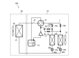
- FIG 3 is a diagram showing the configuration of an air conditioner 100 equipped with an outdoor unit 10 of the air conditioner according to embodiment 1.
- the air conditioner 100 is equipped with an outdoor unit 10 and an indoor unit 20 of the air conditioner (hereinafter also simply referred to as the indoor unit 20).
- the outdoor unit 10 is equipped with a compressor 11, a flow switching device 12, an outdoor heat exchanger 30 (first heat exchanger 30a, second heat exchanger 30b), an accumulator 13, a throttling device 14 (14a, 14b), an outdoor blower 15, a flow rate adjustment device 16 (16a, 16b), and a bypass circuit 2 (2a, 2b).
- the indoor unit 20 is equipped with an indoor heat exchanger 21 and an indoor blower 22.
- an air conditioner 100 having one outdoor unit 10 and one indoor unit 20 is illustrated, but the air conditioner 100 may have two or more outdoor units 10 and indoor units 20.
- the compressor 11, the flow switching device 12, the indoor heat exchanger 21, the throttling device 14 (14a, 14b), the outdoor heat exchanger 30 (first heat exchanger 30a, second heat exchanger 30b), the flow control device 16 (16a, 16b), and the accumulator 13 are connected by a main pipe 41 and branch pipes 42 (42a, 42b) to form a main circuit 1 through which the refrigerant circulates.
- the flow control device 16a, the first heat exchanger 30a, and the throttling device 14a are connected in series by the branch pipe 42a
- the flow control device 16b, the second heat exchanger 30b, and the throttling device 14b are connected in series by the branch pipe 42b, and they are connected in parallel with each other.
- the refrigerant circuit of the air conditioner 100 is composed of this main circuit 1 and a bypass circuit 2 (2a, 2b) described later.
- Compressor 11 draws in low-temperature, low-pressure refrigerant, compresses it, and discharges high-temperature, high-pressure refrigerant.
- Compressor 11 is, for example, an inverter compressor whose capacity, which is the amount of refrigerant discharged per unit time, is controlled by changing the operating frequency.
- the flow path switching device 12 is, for example, a four-way valve, and switches between cooling operation and heating operation by switching the direction of the refrigerant flow. Note that instead of a four-way valve, a combination of a two-way valve and a three-way valve may also be used as the flow path switching device 12.
- the outdoor heat exchanger 30 is composed of a first heat exchanger 30a and a second heat exchanger 30b that operate independently of each other.
- the first heat exchanger 30a and the second heat exchanger 30b exchange heat between, for example, the outdoor air, which is the air outside the room, and the refrigerant, and act as a condenser during cooling operation and as an evaporator during heating operation.
- the outdoor blower 15 is provided near the outdoor heat exchanger 30 and sends outdoor air to the outdoor heat exchanger 30.
- the throttling device 14 (14a, 14b) reduces the pressure of the refrigerant and expands it.
- the throttling device 14 (14a, 14b) is, for example, an electronic expansion valve that can adjust the opening of the throttling, and by adjusting the opening, the pressure of the refrigerant flowing into the indoor heat exchanger 21 is controlled during cooling operation, and the pressure of the refrigerant flowing into the outdoor heat exchanger 30 is controlled during heating operation.
- the accumulator 13 is provided on the suction side of the compressor 11 and is intended to store excess refrigerant that occurs due to differences in operating conditions between cooling and heating, or excess refrigerant due to transient changes in operation.
- Flow rate control device 16a is provided in branch pipe 42a and adjusts the amount of refrigerant flowing through branch pipe 42a.
- Flow rate control device 16b is provided in branch pipe 42b and adjusts the amount of refrigerant flowing through branch pipe 42b.
- the flow rate control devices 16 (16a, 16b) can be any device that is at least capable of opening and closing the flow path, and are composed of, for example, a solenoid valve or a two-way valve.
- the bypass circuit 2 (2a, 2b) includes a bypass pipe 43 (43a, 43b) and a bypass flow control device 17 (17a, 17b).
- the bypass circuit 2a is a circuit that allows a portion of the refrigerant discharged from the compressor 11 to flow from the main pipe 41 between the compressor 11 and the flow switching device 12 to the branch pipe 42a between the first heat exchanger 30a and the flow control device 16a.
- the bypass circuit 2b is a circuit that allows a portion of the refrigerant discharged from the compressor 11 to flow from the main pipe 41 between the compressor 11 and the flow switching device 12 to the branch pipe 42b between the second heat exchanger 30b and the flow control device 16b.
- the bypass pipe 43a is a pipe that bypasses the main pipe 41 between the compressor 11 and the flow path switching device 12 to the branch pipe 42a between the first heat exchanger 30a and the flow control device 16a.
- the bypass pipe 43b is a pipe that bypasses the main pipe 41 between the compressor 11 and the flow path switching device 12 to the branch pipe 42b between the second heat exchanger 30b and the flow control device 16b.
- the bypass flow rate control device 17a is provided in the bypass pipe 43a and adjusts the amount of refrigerant flowing through the bypass pipe 43a.
- the bypass flow rate control device 17b is provided in the bypass pipe 43b and adjusts the amount of refrigerant flowing through the bypass pipe 43b.
- the bypass flow rate control devices 17 (17a, 17b) can be any device that is at least capable of opening and closing the flow path, and are, for example, composed of a solenoid valve or a two-way valve.
- the indoor heat exchanger 21 exchanges heat between the indoor air that is the space to be air-conditioned and the refrigerant, and acts as an evaporator during cooling operation and as a condenser during heating operation.
- the indoor blower 22 is provided near the indoor heat exchanger 21 and sends indoor air to the indoor heat exchanger 21.
- a fluorocarbon refrigerant for example, a fluorocarbon refrigerant, an HFO refrigerant, etc.
- a fluorocarbon refrigerant for example, there are HFC refrigerants such as R32 refrigerant, R125, and R134a.
- HFC refrigerant mixed refrigerants such as R410A, R407c, and R404A.
- HFO refrigerant for example, there are HFO-1234yf, HFO-1234ze(E), and HFO-1234ze(Z).
- refrigerants used in vapor compression heat pump circuits such as CO2 refrigerant, HC refrigerant, ammonia refrigerant, and a mixed refrigerant of R32 and HFO-1234yf, etc.
- CO2 refrigerant for example, propane, isobutane refrigerant, etc.
- HC refrigerant for example, propane, isobutane refrigerant, etc.
- the air conditioner 100 has three operating modes: a cooling operation mode, a normal heating operation mode, and a heating/defrost operation mode.
- the cooling operation mode is a mode in which the indoor unit 20 performs cooling operation, with the outdoor heat exchanger 30 acting as a condenser and the indoor unit 20 cooling the room.
- the normal heating operation mode is a mode in which the indoor unit 20 performs heating operation, with the outdoor heat exchanger 30 acting as an evaporator and the indoor unit 20 heating the room.
- the heating/defrost operation mode is a mode in which the indoor unit 20 performs heating operation, with a portion of the outdoor heat exchanger 30 being the defrost target, that is, one of the first heat exchanger 30a and the second heat exchanger 30b being the defrost target and the other acting as an evaporator and the indoor unit 20 heating the room.
- the heating/defrosting operation mode is an operation mode in which one of the first heat exchanger 30a and the second heat exchanger 30b acts as an evaporator while the other is defrosting, thereby maintaining heating operation while defrosting.
- the first heat exchanger 30a and the second heat exchanger 30b are alternately defrosted.
- one of the first heat exchanger 30a and the second heat exchanger 30b acts as an evaporator to perform heating operation while the other is defrosted.
- the heating/defrosting operation mode when the defrosting of the other is completed, the other acts as an evaporator to perform heating operation and one is defrosted.
- the heating/defrosting operation mode is performed when the first heat exchanger 30a and the second heat exchanger 30b are frosted during normal heating operation.
- the heating/defrosting mode may be switched to when the drive frequency of the compressor 11 becomes lower than the frequency threshold value.
- the control device 50 controls the cooling and heating operations of the indoor unit 20, changes to the set room temperature, the throttling device 14, the flow control device 16, and the bypass flow control device 17.
- the control device 50 according to the first embodiment is composed of a microcomputer having a control arithmetic processing device such as a CPU (Central Processing Unit).
- the control device 50 also has a memory device (not shown) and has data in the form of programs that contain processing procedures related to control, etc. Then, the control arithmetic processing device executes processing based on the program data to realize control.
- the compressor 11 compresses the refrigerant sucked in and discharges the refrigerant in a high-temperature, high-pressure gas state.
- the high-temperature, high-pressure gas state refrigerant discharged from the compressor 11 passes through the flow switching device 12 and branches, then passes through the flow control device 16a and the flow control device 16b, respectively, and flows into the first heat exchanger 30a and the second heat exchanger 30b, which act as condensers.
- the refrigerant exchanges heat with the outdoor air sent by the outdoor blower 15, condenses and liquefies, and becomes a medium-temperature, high-pressure liquid refrigerant.
- the condensed medium-temperature, high-pressure liquid refrigerant flows into the throttling device 14a and the throttling device 14b, respectively.
- the medium-temperature, high-pressure liquid refrigerant that flows into the throttling device 14a and the throttling device 14b is expanded and decompressed in the throttling device 14a and the throttling device 14b, becoming a low-temperature, low-pressure two-phase gas-liquid refrigerant.
- the indoor heat exchanger 21 acts as an evaporator, where it exchanges heat with the indoor air sent by the indoor blower 22, evaporating and gasifying. At this time, the indoor air is cooled, and cooling is performed inside the room.
- the evaporated low-temperature, low-pressure gaseous refrigerant passes through the flow switching device 12 and the accumulator 13 and is sucked into the compressor 11.
- the compressor 11 compresses the refrigerant it draws in and discharges it in a high-temperature, high-pressure gas state.
- the high-temperature, high-pressure gas state refrigerant discharged from the compressor 11 passes through the flow switching device 12 and flows into the indoor heat exchanger 21, which acts as a condenser.
- the indoor heat exchanger 21 the refrigerant exchanges heat with the indoor air sent by the indoor blower 22, condenses and liquefies, and becomes a medium-temperature, high-pressure liquid refrigerant.
- the indoor air is warmed and heating is performed inside the room.
- the condensed medium-temperature, high-pressure liquid refrigerant branches and then flows into the throttling device 14a and the throttling device 14b, respectively.
- the medium-temperature, high-pressure refrigerant that flows into the throttling device 14a and the throttling device 14b is expanded and reduced in pressure to become a medium-pressure gas-liquid two-phase refrigerant.
- the gas-liquid two-phase refrigerant flows into the first heat exchanger 30a and the second heat exchanger 30b, which act as evaporators, respectively.
- the refrigerant exchanges heat with the outdoor air sent by the outdoor blower 15 in the first heat exchanger 30a and the second heat exchanger 30b, evaporating and gasifying.
- the evaporated low-temperature, low-pressure gaseous refrigerant passes through the flow control device 16a and the flow control device 16b, respectively, and merges, then passes through the flow switching device 12 and the accumulator 13 and is sucked into the compressor 11.
- Heating/defrosting operation mode the flow path switching device 12 is switched as shown by the solid line in FIG. 3, the discharge side of the compressor 11 is connected to the indoor heat exchanger 21, and the suction side of the compressor 11 is connected to the first heat exchanger 30a and the second heat exchanger 30b.
- the heating/defrosting operation mode one of the first heat exchanger 30a and the second heat exchanger 30b is selected as the defrosting target and defrosting is performed, and the other acts as an evaporator to continue the heating operation.
- the open/closed states of the flow rate control devices 16a and 16b, and the bypass flow rate control devices 17a and 17a are alternately switched, and the defrosting target is alternately switched between the first heat exchanger 30a and the second heat exchanger 30b.
- the flow of the refrigerant is switched by switching between the first heat exchanger 30a or the second heat exchanger 30b to be defrosted and the first heat exchanger 30a or the second heat exchanger 30b acting as an evaporator.
- the flow control device 16b and the bypass flow control device 17a are open, and the flow control device 16a and the bypass flow control device 17b are closed.
- the compressor 11 compresses the refrigerant it draws in and discharges the refrigerant in a high-temperature, high-pressure gas state.
- a portion of the high-temperature, high-pressure gas state refrigerant discharged from the compressor 11 passes through the flow switching device 12 and flows into the indoor heat exchanger 21, which acts as a condenser.
- the indoor heat exchanger 21 the refrigerant exchanges heat with the indoor air sent by the indoor blower 22, condenses and liquefies, becoming a medium-temperature, high-pressure liquid refrigerant.
- the condensed medium-temperature, high-pressure liquid refrigerant flows into the throttling device 14b.
- the medium-temperature, high-pressure refrigerant that flows into the throttling device 14b is expanded and reduced in pressure, becoming a medium-pressure two-phase gas-liquid refrigerant.
- the refrigerant in the gas-liquid two-phase state does not flow to the first heat exchanger 30a, which is the defrost target, but flows into the second heat exchanger 30b, which acts as an evaporator, where it exchanges heat with the outdoor air sent by the outdoor blower 15, evaporating and gasifying.
- the evaporated low-temperature, low-pressure gaseous refrigerant passes through the flow control device 16b, the flow switching device 12, and the accumulator 13 and is sucked into the compressor 11.
- a part of the high-temperature, high-pressure gaseous refrigerant discharged from the compressor 11 flows into the bypass pipe 43a without passing through the flow switching device 12.
- the refrigerant that flows into the bypass pipe 43a passes through the bypass flow control device 17a and flows into the first heat exchanger 30a to be defrosted.
- the refrigerant that flows into the first heat exchanger 30a is cooled by heat exchange with the frost that has adhered to the first heat exchanger 30a. In this way, the high-temperature, high-pressure gaseous refrigerant discharged from the compressor 11 flows into the first heat exchanger 30a, melting the frost that has adhered to the first heat exchanger 30a.
- the refrigerant that flows out of the first heat exchanger 30a after defrosting the first heat exchanger 30a passes through the throttling device 14a and merges with the medium-temperature, high-pressure liquid refrigerant that has been condensed in the indoor heat exchanger 21.
- the second heat exchanger 30b is selected as the defrost target, and the second heat exchanger 30b is defrosted while the first heat exchanger 30a acts as an evaporator to continue heating.
- the flow control device 16a and the bypass flow control device 17b are open, and the flow control device 16b and the bypass flow control device 17a are closed.
- the compressor 11 compresses the refrigerant it draws in and discharges the refrigerant in a high-temperature, high-pressure gas state.
- a portion of the high-temperature, high-pressure gas state refrigerant discharged from the compressor 11 passes through the flow switching device 12 and flows into the indoor heat exchanger 21, which acts as a condenser.
- the indoor heat exchanger 21 the refrigerant exchanges heat with the indoor air sent by the indoor blower 22, condenses and liquefies, becoming a medium-temperature, high-pressure liquid refrigerant.
- the condensed medium-temperature, high-pressure liquid refrigerant flows into the throttling device 14a.
- the medium-temperature, high-pressure refrigerant that flows into the throttling device 14a is expanded and reduced in pressure, becoming a medium-pressure two-phase gas-liquid refrigerant.
- the refrigerant in the gas-liquid two-phase state does not flow to the second heat exchanger 30b, which is the defrosting target, but flows into the first heat exchanger 30a, which acts as an evaporator, where it exchanges heat with the outdoor air sent by the outdoor blower 15, evaporating and gasifying.
- the evaporated low-temperature, low-pressure gaseous refrigerant passes through the flow control device 16a, the flow path switching device 12, and the accumulator 13 and is sucked into the compressor 11.
- a part of the high-temperature, high-pressure gaseous refrigerant discharged from the compressor 11 flows into the bypass pipe 43b without passing through the flow switching device 12.
- the refrigerant that flows into the bypass pipe 43b passes through the bypass flow control device 17b and flows into the second heat exchanger 30b to be defrosted.
- the refrigerant that flows into the second heat exchanger 30b is cooled by heat exchange with the frost that has adhered to the second heat exchanger 30b. In this way, the high-temperature, high-pressure gaseous refrigerant discharged from the compressor 11 flows into the second heat exchanger 30b, melting the frost that has adhered to the second heat exchanger 30b.
- the refrigerant that flows out of the second heat exchanger 30b after defrosting the second heat exchanger 30b passes through the throttling device 14b and merges with the medium-temperature, high-pressure liquid refrigerant that has been condensed in the indoor heat exchanger 21.
- FIG. 4 is a schematic diagram of the outdoor heat exchanger 30 of the outdoor unit 10 of the air conditioner according to the first embodiment, seen from the front side. As shown in FIG. 4, the first heat exchanger 30a and the second heat exchanger 30b are arranged at intervals in the left-right direction (horizontal direction).
- the first heat exchanger 30a and the second heat exchanger 30b are of a fin tube type, and each of them is arranged at intervals in the left-right direction (horizontal direction), and includes a plurality of heat transfer tubes 33 extending in the up-down direction (vertical direction), plate-shaped fins 34 provided between adjacent heat transfer tubes 33 and extending in the up-down direction (vertical direction), an upper header 31 provided above the plurality of heat transfer tubes 33 and into which the upper ends of the plurality of heat transfer tubes 33 are inserted, and a lower header 32 provided below the plurality of heat transfer tubes 33 and into which the lower ends of the plurality of heat transfer tubes 33 are inserted.
- the heat transfer tubes 33 are arranged in parallel in the left-right direction (horizontal direction) at intervals so that the wind generated by the outdoor blower 15 can flow, and the refrigerant flows in the up-down direction (vertical direction) inside the tubes extending in the up-down direction (vertical direction).
- the heat transfer tubes 33 are, for example, flat tubes that are heat transfer tubes with an elliptical cross section whose width is greater than its length in a cross section perpendicular to the flow direction of the refrigerant.
- the fins 34 are connected between adjacent heat transfer tubes 33 and transfer heat to the heat transfer tubes 33.
- the fins 34 improve the heat exchange efficiency between the air and the refrigerant, and are, for example, corrugated fins, but are not limited to this.
- the upper header 31 and the lower header 32 extend in the left-right direction (horizontal direction) and are cylindrical bodies with both left and right ends closed, and a space is formed inside through which the refrigerant flows.
- melt water flows from the upper heat transfer tube 33 and concentrates on the lower heat transfer tube 33, so the lower heat transfer tube 33 requires more defrosting capacity, and the amount of refrigerant flowing is small because the head is low and the refrigerant does not flow easily.
- melt water does not concentrate on the upper heat transfer tube 33, so the upper heat transfer tube 33 requires less defrosting capacity than the lower heat transfer tube 33, and the head is high and the amount of refrigerant flowing is large. Therefore, the lower heat transfer tube 33 takes longer to defrost than the upper one, and the time required to complete defrosting is longer.
- first heat exchanger 30a and the second heat exchanger 30b are arranged in the left-right direction, and melt water does not concentrate on either one, so the defrosting capacity required for each heat exchanger becomes uniform, and it is possible to suppress the time required for completing defrosting from becoming long.
- melt water generated when melting frost attached to the surface of one of the first heat exchanger 30a and the second heat exchanger 30b does not flow into the other heat exchanger acting as an evaporator, so the evaporation operation is not hindered, and the deterioration of the heat exchanger performance can be suppressed, and the deterioration of the heating capacity can be suppressed.
- the outdoor unit 10 of the air conditioner comprises a housing 19 forming an outer shell, and a first heat exchanger 30a and a second heat exchanger 30b arranged in the left-right direction within the housing 19.
- the first heat exchanger 30a and the second heat exchanger 30b are each arranged at intervals in the left-right direction and comprise a plurality of heat transfer tubes 33 extending in the vertical direction, an upper header 31 provided above the plurality of heat transfer tubes 33 and into which the upper ends of the plurality of heat transfer tubes 33 are inserted, and a lower header 32 provided below the plurality of heat transfer tubes 33 and into which the lower ends of the plurality of heat transfer tubes 33 are inserted.
- the first heat exchanger 30a and the second heat exchanger 30b arranged in the left-right direction within the housing 19 each have a plurality of heat transfer tubes 33 arranged at intervals in the left-right direction and extending in the up-down direction, so that the refrigerant flowing through each heat transfer tube 33 is uniform, melt water does not concentrate in any place, and the defrosting capacity required for each heat transfer tube 33 is uniform. Furthermore, since the first heat exchanger 30a and the second heat exchanger 30b are arranged in the left-right direction, melt water does not concentrate on either one, and the defrosting capacity required for each heat exchanger is uniform. As a result, it is possible to prevent the time required to complete defrosting from becoming longer, and it is possible to prevent a decrease in heating capacity while maintaining the heating function of the indoor unit 20 of the air conditioner even during defrosting.
- the air conditioner 100 includes the air conditioner outdoor unit 10 and the air conditioner indoor unit 20.
- the air conditioner 100 according to the first embodiment can achieve the same effects as the outdoor unit 10 of the air conditioner described above.
- Embodiment 2 Hereinafter, the second embodiment will be described, but explanations of parts that overlap with the first embodiment will be omitted, and parts that are the same as or equivalent to the first embodiment will be given the same reference numerals.
- FIG. 5 is a schematic diagram of the outdoor heat exchanger 30 of the outdoor unit 10 of the air conditioner according to the second embodiment, viewed from the front side.
- the first heat exchanger 30a and the second heat exchanger 30b are arranged in the left-right direction (horizontal direction), but their headers are in thermal contact with each other.
- the end of the upper header 31 of the first heat exchanger 30a on the second heat exchanger 30b side is in thermal contact with the end of the upper header 31 of the second heat exchanger 30b on the first heat exchanger 30a side
- the end of the lower header 32 of the first heat exchanger 30a on the second heat exchanger 30b side is in thermal contact with the end of the lower header 32 of the second heat exchanger 30b on the first heat exchanger 30a side.
- the upper header 31 of the first heat exchanger 30a and the upper header 31 of the second heat exchanger 30b are integrally formed, and a partition plate 35 made of a heat conductive material such as metal is provided between them.
- the lower header 32 of the first heat exchanger 30a and the lower header 32 of the second heat exchanger 30b are integrally formed, and a partition plate 35 made of a heat conductive material such as metal is provided between them.
- the upper header 31 of the first heat exchanger 30a is in thermal contact with the upper header 31 of the second heat exchanger 30b
- the lower header 32 of the first heat exchanger 30a is in thermal contact with the lower header 32 of the second heat exchanger 30b.
- the headers of the first heat exchanger 30a and the second heat exchanger 30b are brought into thermal contact with each other, so that the high-temperature refrigerant that flows when defrosting one of the first heat exchanger 30a and the second heat exchanger 30b is exchanged with the refrigerant that flows through the other heat exchanger acting as an evaporator.
- Embodiment 3 Hereinafter, the third embodiment will be described, but explanations of parts that overlap with the first and second embodiments will be omitted, and the same parts as or corresponding parts to the first and second embodiments will be given the same reference numerals.
- FIG. 6 is a schematic diagram of the outdoor heat exchanger 30 of the outdoor unit 10 of the air conditioner according to embodiment 3, viewed from the front side.
- the first heat exchanger 30a and the second heat exchanger 30b each have a first inlet/outlet pipe 36 and a second inlet/outlet pipe 37.
- the first inlet/outlet pipe 36 is provided in the upper header 31, and the second inlet/outlet pipe 37 is provided in the lower header 32.
- the first inlet/outlet pipe 36 of the first heat exchanger 30a will also be referred to as the first piping
- the first inlet/outlet pipe 36 of the second heat exchanger 30b will also be referred to as the second piping.
- the first inlet/outlet pipe 36 of the first heat exchanger 30a serves as a refrigerant inlet when the first heat exchanger 30a acts as a condenser, and serves as a refrigerant outlet when the first heat exchanger 30a acts as an evaporator.
- the first inlet/outlet pipe 36 of the second heat exchanger 30b serves as a refrigerant inlet when the second heat exchanger 30b acts as a condenser, and serves as a refrigerant outlet when the second heat exchanger 30b acts as an evaporator.
- the second inlet/outlet pipe 37 of the first heat exchanger 30a serves as a refrigerant outlet when the first heat exchanger 30a acts as a condenser, and serves as a refrigerant inlet when the first heat exchanger 30a acts as an evaporator.
- the second inlet/outlet pipe 37 of the second heat exchanger 30b serves as a refrigerant outlet when the second heat exchanger 30b acts as a condenser, and serves as a refrigerant inlet when the second heat exchanger 30b acts as an evaporator.
- the first inlet/outlet pipe 36 of the first heat exchanger 30a is positioned closer to the second heat exchanger 30b than the lateral center of the upper header 31 (dashed line X1 in FIG. 6), and the first inlet/outlet pipe 36 of the second heat exchanger 30b is positioned closer to the first heat exchanger 30a than the lateral center of the upper header 31 (dashed line X2 in FIG. 6).
- the upper header 31 of the first heat exchanger 30a is provided with a first pipe that serves as an inlet for the refrigerant when the first heat exchanger 30a acts as a condenser
- the upper header 31 of the second heat exchanger 30b is provided with a second pipe that serves as an outlet for the refrigerant when the second heat exchanger 30b acts as an evaporator, the first pipe being positioned closer to the second heat exchanger 30b than the left-right center of the upper header 31, and the second pipe being positioned closer to the first heat exchanger 30a than the left-right center of the upper header 31.
- the first pipe is arranged closer to the second heat exchanger 30b than the left-right center of the upper header 31 of the first heat exchanger 30a
- the second pipe is arranged closer to the first heat exchanger 30a than the left-right center of the upper header 31 of the second heat exchanger 30b.
- Embodiment 4 Hereinafter, the fourth embodiment will be described, but explanations of parts that overlap with the first to third embodiments will be omitted, and the same parts as or corresponding parts to the first to third embodiments will be given the same reference numerals.
- Fig. 7 is a schematic diagram of the outdoor heat exchanger 30 of the outdoor unit 10 of the air conditioner according to embodiment 4, viewed from the front side.
- fins 34 are provided between the heat transfer tube 33 of the first heat exchanger 30a that is arranged closest to the second heat exchanger 30b and the heat transfer tube 33 of the second heat exchanger 30b that is arranged closest to the first heat exchanger 30a (see the Y arrow portion in Fig. 7), and the heat transfer tube 33 of the first heat exchanger 30a and the heat transfer tube 33 of the second heat exchanger 30b are in thermal contact with each other.
- the heat transfer tubes 33 of the first heat exchanger 30a and the heat transfer tubes 33 of the second heat exchanger 30b are in thermal contact via the fins 34, so that when the entire outdoor heat exchanger 30 (i.e., both the first heat exchanger 30a and the second heat exchanger 30b) is used as an evaporator or a condenser, the heat transfer area of the fins 34 increases, improving the heat exchanger performance.
- the outdoor unit 10 of the air conditioner according to embodiment 4 has fins 34 provided between the heat transfer tube 33 arranged on the first heat exchanger 30a closest to the second heat exchanger 30b and the heat transfer tube 33 arranged on the second heat exchanger 30b closest to the first heat exchanger 30a.
- the heat transfer tubes 33 of the first heat exchanger 30a and the heat transfer tubes 33 of the second heat exchanger 30b are in thermal contact via the fins 34, so that when all of the outdoor heat exchangers 30 (i.e., both the first heat exchanger 30a and the second heat exchanger 30b) are used as evaporators or condensers, the heat transfer area of the fins 34 increases, improving the heat exchanger performance.
- Embodiment 5 Hereinafter, the fifth embodiment will be described, but explanations of parts that overlap with the first to fourth embodiments will be omitted, and the same parts as or corresponding parts to the first to fourth embodiments will be given the same reference numerals.
- FIG 8 is a schematic diagram of the outdoor heat exchanger 30 of the outdoor unit 10 of the air conditioner according to embodiment 5, viewed from the front side.
- no fins 34 are provided between the heat transfer tube 33 of the first heat exchanger 30a that is arranged closest to the second heat exchanger 30b and the heat transfer tube 33 of the second heat exchanger 30b that is arranged closest to the first heat exchanger 30a (see the Z arrow in Figure 8), and the heat transfer tube 33 of the first heat exchanger 30a and the heat transfer tube 33 of the second heat exchanger 30b are thermally insulated from each other.
- Embodiment 6 Hereinafter, the sixth embodiment will be described, but explanations of parts that overlap with the first to fifth embodiments will be omitted, and the same parts as or corresponding parts to the first to fifth embodiments will be given the same reference numerals.
- liquid refrigerant accumulates in the one of the first heat exchanger 30a and the second heat exchanger 30b that is to be defrosted, and the liquid refrigerant in the indoor heat exchanger 21 decreases by the amount of the increase in liquid refrigerant present in the outdoor heat exchanger 30. If the heat transfer tubes of the outdoor heat exchanger 30 and the heat transfer tubes of the indoor heat exchanger 21 are both made of circular tubes, the indoor heat exchanger 21 will experience a refrigerant shortage during heating, and the heating capacity will decrease.
- the heat transfer tube 33 of the outdoor heat exchanger 30 a flat multi-hole tube with a smaller flow cross-sectional area than a circular tube, if the heat transfer tube of the indoor heat exchanger 21 is made of a circular tube, even if the liquid refrigerant present in the outdoor heat exchanger 30 increases, it is possible to suppress the decrease in heating capacity because it does not greatly affect the amount of refrigerant required by the indoor heat exchanger 21.
- the first heat exchanger 30a and the second heat exchanger 30b are each a flat multi-hole tube in which the heat transfer tube 33 forms a plurality of refrigerant flow paths 33a arranged along the longitudinal direction.
- the heat transfer tubes 33 of the outdoor heat exchanger 30 are made of flat multi-hole tubes.
- the heat transfer tubes of the indoor heat exchanger 21 are made of circular tubes, an increase in the amount of liquid refrigerant present in the outdoor heat exchanger 30 does not significantly affect the amount of refrigerant required by the indoor heat exchanger 21, so a decrease in heating capacity can be suppressed.
Landscapes
- Engineering & Computer Science (AREA)
- Physics & Mathematics (AREA)
- Mechanical Engineering (AREA)
- Thermal Sciences (AREA)
- General Engineering & Computer Science (AREA)
- Other Air-Conditioning Systems (AREA)
Priority Applications (2)
| Application Number | Priority Date | Filing Date | Title |
|---|---|---|---|
| JP2025532323A JPWO2025013244A1 (https=) | 2023-07-12 | 2023-07-12 | |
| PCT/JP2023/025731 WO2025013244A1 (ja) | 2023-07-12 | 2023-07-12 | 空気調和機の室外機およびそれを備えた空気調和機 |
Applications Claiming Priority (1)
| Application Number | Priority Date | Filing Date | Title |
|---|---|---|---|
| PCT/JP2023/025731 WO2025013244A1 (ja) | 2023-07-12 | 2023-07-12 | 空気調和機の室外機およびそれを備えた空気調和機 |
Publications (1)
| Publication Number | Publication Date |
|---|---|
| WO2025013244A1 true WO2025013244A1 (ja) | 2025-01-16 |
Family
ID=94214808
Family Applications (1)
| Application Number | Title | Priority Date | Filing Date |
|---|---|---|---|
| PCT/JP2023/025731 Pending WO2025013244A1 (ja) | 2023-07-12 | 2023-07-12 | 空気調和機の室外機およびそれを備えた空気調和機 |
Country Status (2)
| Country | Link |
|---|---|
| JP (1) | JPWO2025013244A1 (https=) |
| WO (1) | WO2025013244A1 (https=) |
Citations (6)
| Publication number | Priority date | Publication date | Assignee | Title |
|---|---|---|---|---|
| CN201844618U (zh) * | 2010-07-30 | 2011-05-25 | 艾默生网络能源有限公司 | 一种微通道蒸发器 |
| WO2014083650A1 (ja) * | 2012-11-29 | 2014-06-05 | 三菱電機株式会社 | 空気調和装置 |
| WO2015063853A1 (ja) * | 2013-10-29 | 2015-05-07 | 株式会社日立製作所 | 冷凍サイクルおよび空気調和機 |
| WO2016174830A1 (ja) * | 2015-04-27 | 2016-11-03 | ダイキン工業株式会社 | 熱交換器および空気調和機 |
| WO2019239446A1 (ja) * | 2018-06-11 | 2019-12-19 | 三菱電機株式会社 | 空気調和装置の室外機及び空気調和装置 |
| WO2023062801A1 (ja) * | 2021-10-15 | 2023-04-20 | 三菱電機株式会社 | 熱交換器及び空気調和装置 |
-
2023
- 2023-07-12 WO PCT/JP2023/025731 patent/WO2025013244A1/ja active Pending
- 2023-07-12 JP JP2025532323A patent/JPWO2025013244A1/ja active Pending
Patent Citations (6)
| Publication number | Priority date | Publication date | Assignee | Title |
|---|---|---|---|---|
| CN201844618U (zh) * | 2010-07-30 | 2011-05-25 | 艾默生网络能源有限公司 | 一种微通道蒸发器 |
| WO2014083650A1 (ja) * | 2012-11-29 | 2014-06-05 | 三菱電機株式会社 | 空気調和装置 |
| WO2015063853A1 (ja) * | 2013-10-29 | 2015-05-07 | 株式会社日立製作所 | 冷凍サイクルおよび空気調和機 |
| WO2016174830A1 (ja) * | 2015-04-27 | 2016-11-03 | ダイキン工業株式会社 | 熱交換器および空気調和機 |
| WO2019239446A1 (ja) * | 2018-06-11 | 2019-12-19 | 三菱電機株式会社 | 空気調和装置の室外機及び空気調和装置 |
| WO2023062801A1 (ja) * | 2021-10-15 | 2023-04-20 | 三菱電機株式会社 | 熱交換器及び空気調和装置 |
Also Published As
| Publication number | Publication date |
|---|---|
| JPWO2025013244A1 (https=) | 2025-01-16 |
Similar Documents
| Publication | Publication Date | Title |
|---|---|---|
| JP6685409B2 (ja) | 空気調和装置 | |
| JP5625691B2 (ja) | 冷凍装置 | |
| WO2018051408A1 (ja) | 空気調和装置 | |
| JP7433470B2 (ja) | 冷凍サイクル装置 | |
| KR100539570B1 (ko) | 멀티공기조화기 | |
| JP6846915B2 (ja) | 多室型空気調和機 | |
| JP4428341B2 (ja) | 冷凍サイクル装置 | |
| CN113339909B (zh) | 热泵空调系统 | |
| JP7123238B2 (ja) | 冷凍サイクル装置 | |
| JP6198976B2 (ja) | 熱交換器、及び冷凍サイクル装置 | |
| WO2021065914A1 (ja) | 冷凍装置 | |
| WO2020235030A1 (ja) | 熱交換器およびそれを用いた冷凍サイクル装置 | |
| WO2025013244A1 (ja) | 空気調和機の室外機およびそれを備えた空気調和機 | |
| WO2021106084A1 (ja) | 冷凍サイクル装置 | |
| JP4983878B2 (ja) | 熱交換器及びこの熱交換器を備えた冷蔵庫、空気調和機 | |
| JP7595770B2 (ja) | 熱交換器および冷凍サイクル装置 | |
| JP7851511B1 (ja) | 熱交換器、冷凍サイクル装置の室外機、および冷凍サイクル装置 | |
| JP7760076B1 (ja) | 空気調和装置 | |
| US20260029177A1 (en) | Heat exchanger and refrigeration cycle apparatus including heat exchanger | |
| EP4513106A1 (en) | Refrigeration device | |
| JP2008170134A (ja) | 冷凍装置 | |
| WO2024261859A1 (ja) | 空気調和装置 | |
| WO2025182083A1 (ja) | 熱交換器、熱交換器を備えた空気調和装置の室外機、および、空気調和装置の室外機を備えた空気調和装置 | |
| JP2025007831A (ja) | 冷凍装置 | |
| WO2023188421A1 (ja) | 室外機およびそれを備えた空気調和装置 |
Legal Events
| Date | Code | Title | Description |
|---|---|---|---|
| 121 | Ep: the epo has been informed by wipo that ep was designated in this application |
Ref document number: 23945119 Country of ref document: EP Kind code of ref document: A1 |
|
| ENP | Entry into the national phase |
Ref document number: 2025532323 Country of ref document: JP Kind code of ref document: A |
|
| WWE | Wipo information: entry into national phase |
Ref document number: 2025532323 Country of ref document: JP |
|
| NENP | Non-entry into the national phase |
Ref country code: DE |