WO2025013239A1 - 観測装置、観測システム、観測方法、及びプログラム - Google Patents
観測装置、観測システム、観測方法、及びプログラム Download PDFInfo
- Publication number
- WO2025013239A1 WO2025013239A1 PCT/JP2023/025712 JP2023025712W WO2025013239A1 WO 2025013239 A1 WO2025013239 A1 WO 2025013239A1 JP 2023025712 W JP2023025712 W JP 2023025712W WO 2025013239 A1 WO2025013239 A1 WO 2025013239A1
- Authority
- WO
- WIPO (PCT)
- Prior art keywords
- observation device
- avoidance
- observation
- unit
- lidar
- Prior art date
- Legal status (The legal status is an assumption and is not a legal conclusion. Google has not performed a legal analysis and makes no representation as to the accuracy of the status listed.)
- Pending
Links
Images



Classifications
-
- G—PHYSICS
- G08—SIGNALLING
- G08G—TRAFFIC CONTROL SYSTEMS
- G08G3/00—Traffic control systems for marine craft
- G08G3/02—Anti-collision systems
Definitions
- This disclosure relates to an observation device, an observation system, an observation method, and a program.
- Non-patent document 1 discloses that AIS information such as a ship's identification code, name, position, course, speed, and destination is automatically transmitted and received using VHF radio waves, and information is exchanged between ship stations and between ship stations and land stations.
- AIS information such as a ship's identification code, name, position, course, speed, and destination is automatically transmitted and received using VHF radio waves, and information is exchanged between ship stations and between ship stations and land stations.
- Non-Patent Document 2 discloses a technology that receives AIS information transmitted from other ships when observing ocean data such as seawater temperature and tidal currents using an autonomous ocean observation device (AOV; Autonomous Ocean Vehicle), and prevents collisions between ships using a collision prevention function.
- AOV autonomous ocean observation device
- the collision prevention function of AOVs is an autonomous control function based on receiving AIS information transmitted by nearby ships.
- AIS information As disclosed in Non-Patent Document 3, ship registration is required, and currently, large ships of 300 tons or more are required to install AIS. For this reason, small ships, small marine observation equipment, etc. are not equipped with AIS and cannot transmit AIS information.
- Japan Coast Guard https://www.kaiho.mlit.go.jp/soshiki/koutsuu/ais-info.html
- Japan Coast Guard Marine Information Department Research Report https://www1.kaiho.mlit.go.jp/GIJUTSUKOKUSAI/KENKYU/report/rhr54/rhr54-TR04.pdf
- AIS registration eligible vessels https://jci.go.jp/registration/taishou.html
- This disclosure has been made in consideration of the above circumstances, and its purpose is to provide an observation device, observation system, observation method, and program that can avoid collisions with structures even when structures that do not transmit AIS information are present.
- An observation device is an observation device that observes oceanographic data, and includes a lidar that emits laser light to the surroundings and receives the reflected light, a detection unit that detects structure data including at least one of the distance to structures present around the lidar and the size of the structures based on the reflected light, a determination unit that determines whether or not to perform evasive navigation to avoid a collision with the structures based on the structure data, and an avoidance control unit that performs the evasive navigation when it is determined that the evasive navigation should be performed.
- An observation system is an observation system including an observation device that observes ocean data and a management device capable of communicating with the observation device, the observation device including a lidar that irradiates a laser beam to the surroundings and receives the reflected light, a detection unit that detects structure data including at least one of the distance to structures present around the lidar and the size of the structures based on the reflected light, a determination unit that determines whether or not to perform evasive navigation to avoid a collision with the structure based on the structure data, an avoidance control unit that performs the evasive navigation when it is determined that the evasive navigation should be performed, and a first communication unit that communicates with the management device, and the management device includes an avoidance action memory unit that stores evasive navigation information transmitted from the observation device, and an access unit that outputs the evasive navigation information to the outside in response to an external request.
- An observation method is a method for observing oceanographic data, which involves irradiating a laser beam from a lidar to the surroundings, receiving the reflected light, detecting structure data including at least one of the distance to structures present around the lidar and the size of the structures based on the reflected light, determining whether or not to perform evasive navigation to avoid a collision with the structures based on the structure data, and executing the evasive navigation when it is determined that the evasive navigation should be performed.
- One aspect of the present disclosure is a program for causing a computer to function as the above-mentioned observation device.
- This disclosure makes it possible to avoid collisions with structures even when there are structures that do not transmit AIS information.
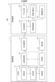
- FIG. 1 is a block diagram showing the configuration of an observation system according to an embodiment.
- FIG. 2 is an explanatory diagram showing a schematic diagram of a LIDAR mounted on the top of a mast installed in an observation device.
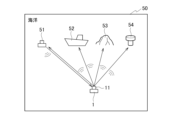
- FIG. 3 is an explanatory diagram that shows a schematic diagram of how a laser beam emitted from a lidar is used to horizontally scan and detect structures present in the ocean.
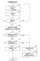
- FIG. 4 is a flowchart showing the processing procedure of the observation device.
- FIG. 5 is a flowchart showing a processing procedure of the management device.
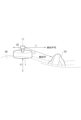
- FIG. 6 is an explanatory diagram showing how the position of the LIDAR moves up and down due to the influence of waves, causing the detection area to change.
- FIG. 7 is a block diagram showing the hardware configuration of this embodiment.
- Fig. 1 is a block diagram showing the configuration of an observation system 100 according to the embodiment.
- the observation system 100 includes an observation device 1 and a management device 2.
- the observation device 1 is, for example, an autonomous ocean observation vehicle (AOV) that autonomously navigates the ocean and observes ocean data such as seawater temperature and tidal currents.
- the management device 2 is installed, for example, at a base station on land.
- AOV autonomous ocean observation vehicle
- the observation device 1 includes a LiDAR (Light Detection And Ranging) 11, a detection unit 13, a determination unit 14, an avoidance control unit 15, a storage unit 16, and a first communication unit 17.
- the observation device 1 avoids collisions between the observation device 1 and marine structures (hereinafter abbreviated as "structures") by linking information on the marine structures detected by the LiDAR 11 with a collision prevention control process (not shown).
- Structures refer to, for example, unmanned seaplanes, small boats, reefs, floating fishing reefs, etc. that exist in the ocean.
- the LIDAR 11 is, for example, a solid-state LIDAR.
- the LIDAR 11 is installed at the top of a mast 32 provided on an observation device 1 that navigates the ocean, as shown in FIG. 2.
- the mast 32 has, for example, a rod shape that extends vertically to the observation device 1.
- the LIDAR 11 comprises an irradiation unit 111 and a light receiving unit 112.
- the irradiation unit 111 irradiates laser light in the surroundings (e.g., 360° horizontally).
- the light receiving unit 112 receives the laser light irradiated from the irradiation unit 111 and reflected by surrounding structures. In other words, the LIDAR 11 irradiates the surroundings with laser light and receives the reflected light.
- the LIDAR 11 uses a short-wavelength laser light, which has a higher luminous flux density than radio waves used in automatic identification systems (AIS) and the like, and can therefore detect the position and shape of structures with high accuracy.
- AIS automatic identification systems
- the observation device 1 sailing through the ocean moves up and down due to the influence of waves.
- the LIDAR 11 By installing the LIDAR 11 at the top of the mast 32, the surrounding structures can be placed within the detection area of the LIDAR 11. Specifically, as shown in FIG. 2, the area at an angle d1 above the horizontal direction s1 of the LIDAR 11 is an area in which structures cannot be detected, and the area at an angle d2 below is an area in which structures can be detected.
- the LIDAR 11 at the top of the mast 32 even if the observation device 1 moves up and down due to the influence of waves, structures present around the observation device 1 can be detected with a high probability.
- FIG 3 is an explanatory diagram that shows a schematic diagram of how a laser beam emitted from the LIDAR 11 is used to horizontally scan and detect structures in the ocean 50.
- the LIDAR 11 emits laser beams and receives reflected light from an unmanned surface vehicle 51 and a small boat 52 traveling in the ocean 50 to detect their presence. It also receives reflected light from reefs 53 and floating fishing reefs 54 in the ocean 50 to detect their presence.
- the unmanned surface vehicle 51 is equipped with a LIDAR receiving and transmitting function, collision avoidance between both the observation device 1 and the unmanned surface vehicle 51 is possible.
- the detection unit 13 performs three-dimensional measurements of structures present around the observation device 1 based on the detection signal detected by the light receiving unit 112, and detects the distance to the structures, their size, and their shape.
- the detection unit 13 outputs data on the detected distance, size, and shape (collectively referred to below as "structure data") to the determination unit 14 and the first communication unit 17.
- the detection unit 13 may also detect at least one of the distance to the structure and the size of the structure. That is, the detection unit 13 detects structure data including at least one of the distance to the structures present around the lidar 11 and the size of the structures based on the reflected light.
- the determination unit 14 determines whether or not the observation device 1 needs to perform avoidant navigation to avoid a collision with a structure, based on the structure data detected by the detection unit 13.
- the determination unit 14 determines that avoidant navigation is necessary for the observation device 1, for example, when the distance to the structure is equal to or less than a first threshold value, or when the size of the structure is equal to or greater than a second threshold value.
- the determination unit 14 determines that avoidant navigation is necessary for the observation device 1, it outputs an avoidance command signal to the avoidance control unit 15.
- the determination unit 14 determines that avoidant navigation is not necessary for the observation device 1, it outputs the structure data to the storage unit 16.
- the storage unit 16 includes a storage device such as a hard disk.
- the storage unit 16 stores data on structures for which the determination unit 14 has determined that avoidant maneuvering is not necessary.
- the storage unit 16 stores data on structures for which the determination unit 14 has determined that the distance from the observation device 1 is equal to or greater than a first threshold and that the size is less than a second threshold.
- the storage unit 16 stores data on structures that existed around the observation device 1 but for which avoidant maneuvering is not necessary, i.e., near-miss data when the observation device 1 is navigating the ocean.
- the avoidance control unit 15 controls the navigation of the observation device 1 to avoid collision with a structure when an avoidance command signal is output from the judgment unit 14. That is, the avoidance control unit 15 executes avoidance navigation when it is determined that avoidance navigation should be executed.
- the first communication unit 17 is capable of wireless communication with the second communication unit 21 mounted on the management device 2.
- the first communication unit 17 transmits structure data detected by the detection unit 13 and avoidance navigation information implemented by the avoidance control unit 15 to the management device 2. In other words, when avoidance navigation is implemented by the avoidance control unit 15, the first communication unit 17 notifies the base station of the avoidance navigation information.
- the management device 2 includes a second communication unit 21, a management control unit 22, an avoidance behavior DB 23 (avoidance behavior recording unit), a structure DB 24 (structure data recording unit), and an access unit 25.
- DB stands for "database.”
- the second communication unit 21 performs wireless communication with the first communication unit 17 mounted on the observation device 1.
- the second communication unit 21 receives structure data transmitted from the observation device 1, i.e., data on the distance to the structure, and the size and shape of the structure.
- the second communication unit 21 receives avoidance navigation information transmitted from the observation device 1.
- the management control unit 22 outputs the structure data received by the second communication unit 21 to the structure DB 24.
- the management control unit 22 outputs the avoidance navigation information received by the second communication unit 21 to the avoidance action DB 23.
- the avoidance action DB23 includes a storage device such as a hard disk, and stores the avoidance navigation information output from the management control unit 22.
- the structure DB 24 includes a storage device such as a hard disk, and stores the structure data output from the management control unit 22.
- the access unit 25 accepts access from an external device (not shown). For example, when an external device requests the output of avoidance navigation information, the access unit 25 reads out the avoidance navigation information stored in the avoidance action DB 23 and outputs it to the external device. When an external device requests the output of structure data, the access unit 25 reads out the structure data stored in the structure DB 24 and outputs it to the external device. In other words, in response to access from outside, the access unit 25 controls the output of the data stored in the avoidance action DB 23 and the structure DB 24 to the outside.
- Figure 4 is a flowchart showing the processing procedure performed by the observation device 1.
- step S11 the irradiation unit 111 of the LIDAR 11 irradiates laser light in a horizontal direction of 360° at regular time intervals.
- step S12 the light receiving unit 112 of the LIDAR 11 receives the light that is irradiated from the irradiating unit 111 and reflected by structures such as the unmanned surface vehicle 51, small boat 52, reef 53, and floating fishing reef 54 shown in FIG. 3.
- step S13 the detection unit 13 detects structures present around the observation device 1 based on the reflected light received by the light receiving unit 112. If a structure is detected (S13; YES), the process proceeds to step S14; if not (S13; NO), the process returns to step S11.
- step S14 the detection unit 13 detects the distance from the observation device 1 to the structure, and the size and shape of the structure based on the reflected light received by the light receiving unit 112.
- step S15 the determination unit 14 determines whether the distance from the observation device 1 to the structure is equal to or less than a predetermined first threshold. If it is equal to or less than the first threshold (S15; YES), the process proceeds to step S17; if not (S15; NO), the process proceeds to step S16.
- step S16 the determination unit 14 determines whether the size of the structure is equal to or greater than a predetermined second threshold. If it is equal to or greater than the second threshold (S16; YES), the process proceeds to step S17; if not (S16; NO), the process proceeds to step S19.
- step S17 the judgment unit 14 outputs an avoidance command signal to the avoidance control unit 15. That is, if there is a structure within a range of the observation device 1 that is within a first threshold value, or if there is a structure with a size equal to or larger than a second threshold value around the observation device 1, the avoidance command signal is output to avoid collision with these structures.
- the avoidance control unit 15 avoids collision with the structure by performing avoidance navigation. Avoidance navigation includes, for example, changing the direction of travel of the observation device 1, or stopping or reversing the observation device 1.
- step S18 the first communication unit 17 outputs to the management device 2 the structure data detected by the detection unit 13 and the avoidance navigation information indicating that the avoidance control unit 15 has performed avoidance navigation.
- step S19 the storage unit 16 stores the structure data, for example, on a hard disk. That is, the structure data of structures that existed around the observation device 1 but did not result in avoidant navigation, i.e., data on distance, size, and shape, are stored in the storage unit 16.
- the structure data stored in the storage unit 16 can be used later as near-miss data.
- the observation device 1 can control its evasive navigation based on the distance to the structure and the size of the structure, thereby avoiding a collision with the structure.
- step S31 the management control unit 22 determines whether or not avoidance navigation has been performed by the observation device 1.
- avoidant navigation information is transmitted from the first communication unit 17 of the observation device 1, and this avoidant navigation information is received by the second communication unit 21.
- the management control unit 22 determines that avoidant navigation has been performed by the observation device 1. If avoidant navigation has been performed (S31; YES), processing proceeds to step S32; if not (S31; NO), processing proceeds to step S33.
- step S32 the management control unit 22 records the avoidance navigation information from the observation device 1 in the avoidance action DB 23.
- step S33 the management control unit 22 determines whether or not structure data has been received. For example, when the detection unit 13 of the observation device 1 detects a structure existing around the observation device 1, the structure data is transmitted from the first communication unit 17, and this structure data is received by the second communication unit 21. When the structure data is received by the second communication unit 21, the management control unit 22 determines that the structure data has been received. If structure data has been received (S33; YES), processing proceeds to step S34; if not (S33; NO), processing proceeds to step S35.
- step S34 the management control unit 22 records the structure data in the structure DB 24.
- step S35 the access unit 25 determines whether or not there is access from an external device, such as a request to read data. If there is access (S35; YES), the process proceeds to step S36; if not (S35; NO), the process ends.
- step S36 the access unit 25 outputs each data recorded in the avoidance action DB 23 and the structure DB 24 to the external device. After that, this process ends. In this way, it becomes possible for the observation device 1 to record the results of past avoidance navigation and structure data, and to output this information in response to access from an external device.
- the observation system 100 is an observation system 100 including an observation device 1 that observes ocean data, and a management device 2 that can communicate with the observation device 1.
- the observation device 1 includes a LIDAR 11 that irradiates the surroundings with laser light and receives the reflected light, a detection unit 13 that detects structure data including at least one of the distance to structures present around the LIDAR 11 and the size of the structures based on the reflected light, a determination unit 14 that determines whether or not to perform evasive navigation to avoid collision with the structure based on the structure data, an avoidance control unit 15 that performs evasive navigation when it is determined that evasive navigation should be performed, and a first communication unit 17 that communicates with the management device 2.
- the management device 2 includes an evasive action DB 23 (avoidance action storage unit) that stores evasive navigation information transmitted from the observation device 1, and an access unit 25 that outputs evasive navigation information to the outside in response to an external request.
- the lidar 11 is used to detect the distance to small vessels that do not transmit AIS information, reefs, and other structures. This allows structures present around the observation device 1 sailing through the ocean to be detected reliably, making it possible to avoid collisions with the structures. In addition, it is no longer necessary for an observer to constantly monitor the area around the observation device 1, reducing manual labor and enabling costs to be reduced.
- the LIDAR 11 is installed at the top of the mast.
- the reef 53 can be included in the detection range of the LIDAR 11, and structures such as the reef 53 can be detected with high accuracy.
- the laser light emitted by the lidar 11 is a short wave (infrared wavelength) that does not interfere with weather sensors mounted on marine observation equipment, so it is possible to avoid affecting the collection of observation data.
- the storage unit 16 stores data on structures that existed around the observation device 1, even if evasive maneuvers were not required, making it possible to use this data later as near-miss data.
- the system can detect topographical information such as reefs, it is expected to be useful in marine area surveys.
- the observation device 1 of this embodiment described above can be, for example, a general-purpose computer system equipped with a CPU (Central Processing Unit, processor) 901, memory 902, storage 903 (HDD: Hard Disk Drive, SSD: Solid State Drive), communication device 904, input device 905, and output device 906, as shown in FIG. 7.
- the memory 902 and storage 903 are storage devices.
- each function of the observation device 1 is realized by the CPU 901 executing a specific program loaded onto the memory 902.
- observation device 1 may be implemented in one computer, or in multiple computers.
- the observation device 1 may also be a virtual machine implemented in a computer.
- the program for the observation device 1 can be stored on a computer-readable recording medium such as a HDD, SSD, USB (Universal Serial Bus) memory, CD (Compact Disc), or DVD (Digital Versatile Disc), or can be distributed via a network.
- a computer-readable recording medium such as a HDD, SSD, USB (Universal Serial Bus) memory, CD (Compact Disc), or DVD (Digital Versatile Disc), or can be distributed via a network.
- the computer-readable recording medium is, for example, a non-transitory recording medium.
Landscapes
- Engineering & Computer Science (AREA)
- Ocean & Marine Engineering (AREA)
- Radar, Positioning & Navigation (AREA)
- Remote Sensing (AREA)
- Physics & Mathematics (AREA)
- General Physics & Mathematics (AREA)
- Optical Radar Systems And Details Thereof (AREA)
Abstract
周囲にレーザ光を照射し、その反射光を受光するライダー(11)と、反射光に基づいて、ライダー(11)の周囲に存在する構造物までの距離、及び構造物の大きさ、の少なくとも一方を含む構造物データを検知する検知部(13)と、構造物データに基づいて、構造物との衝突を回避する回避航行を実行するか否かを判定する判定部(14)と、回避航行を実行すると判定された際に、回避航行を実行する回避制御部(15)を備える。
Description
本開示は、観測装置、観測システム、観測方法、及びプログラムに関する。
海上を航行する船舶の衝突を防止する技術として、船舶自動識別装置(AIS;Automatic Identification System)によるAIS情報を用いた衝突防止方法が提案されている。非特許文献1には、船舶の識別符号、船名、位置、針路、速力、目的地などのAIS情報をVHF帯の電波で自動的に送受信し、船舶局相互間、船舶局と陸上局間で情報を交換することが開示されている。
非特許文献2には、自律型海洋観測装置(AOV;Autonomous OceanVehicle)により海水温度、潮流などの海洋データを観測する際に、他の船舶から発信されるAIS情報を受信し、衝突防止機能により船舶どうしの衝突を予防する技術が開示されている。
AOVによる衝突防止機能は、周辺の船舶等が発信するAIS情報の受信に基づく自律制御機能である。AIS情報を発信するためには、非特許文献3に開示されているように、船舶登録が必要であり、現状では300トン以上の大型船にAISの設置が義務付けられている。このため、小型船舶、小型海洋観測装置などには、AISが搭載されておらず、AIS情報を送信することができない。
海上保安庁:https://www.kaiho.mlit.go.jp/soshiki/koutsuu/ais-info.html
海上保安庁海洋情報部研究報告:https://www1.kaiho.mlit.go.jp/GIJUTSUKOKUSAI/KENKYU/report/rhr54/rhr54-TR04.pdf
AIS登録対象船舶:https://jci.go.jp/registration/taishou.html
AOV(自律型海洋観測装置)による海洋データの観測を実施する場合には、周囲にAISを備えていない小型船舶などが存在すると、小型船舶との衝突を自動で回避することが難しい。更に、AOVの周囲に岩礁、浮漁礁などが存在する場合においても、これらとの衝突を自動で回避することが難しい。このため、人手による監視作業が必要になるという問題があった。
本開示は、上記事情に鑑みてなされたものであり、その目的とするところは、AIS情報を発信しない構造物が存在する場合でも、構造物との衝突を回避することが可能な観測装置、観測システム、観測方法、及びプログラムを提供することにある。
本開示の一態様の観測装置は、海洋データを観測する観測装置であって、周囲にレーザ光を照射し、その反射光を受光するライダーと、前記反射光に基づいて、前記ライダーの周囲に存在する構造物までの距離、及び前記構造物の大きさ、の少なくとも一方を含む構造物データを検知する検知部と、前記構造物データに基づいて、前記構造物との衝突を回避する回避航行を実行するか否かを判定する判定部と、前記回避航行を実行すると判定された際に、前記回避航行を実行する回避制御部とを備える。
本開示の一態様の観測システムは、海洋データを観測する観測装置、及び前記観測装置と通信可能な管理装置を備えた観測システムであって、前記観測装置は、周囲にレーザ光を照射し、その反射光を受光するライダーと、前記反射光に基づいて、前記ライダーの周囲に存在する構造物までの距離、及び前記構造物の大きさ、の少なくとも一方を含む構造物データを検知する検知部と、前記構造物データに基づいて、前記構造物との衝突を回避する回避航行を実行するか否かを判定する判定部と、前記回避航行を実行すると判定された際に、前記回避航行を実行する回避制御部と、前記管理装置と通信する第1通信部と、を備え、前記管理装置は、前記観測装置から送信された回避航行情報を記憶する回避行動記憶部と、外部からの要求に対して、前記回避航行情報を外部に出力するアクセス部と、を備える。
本開示の一態様の観測方法は、海洋データを観測する観測方法であって、ライダーから周囲にレーザ光を照射し、その反射光を受光し、前記反射光に基づいて、前記ライダーの周囲に存在する構造物までの距離、及び前記構造物の大きさ、の少なくとも一方を含む構造物データを検知し、前記構造物データに基づいて、前記構造物との衝突を回避する回避航行を実行するか否かを判定し、前記回避航行を実行すると判定された際に、前記回避航行を実行する。
本開示の一態様は、上記観測装置としてコンピュータを機能させるためのプログラムである。
本開示によれば、AIS情報を発信しない構造物が存在する場合でも、構造物との衝突を回避することが可能になる。
以下、図面を参照して実施形態について説明する。図1は、実施形態に係る観測システム100の構成を示すブロック図である。図1に示すように観測システム100は、観測装置1と管理装置2を備えている。観測装置1は、例えば海洋を自律航行して海水温度、潮流などの海洋データを観測する自律型海洋観測装置(AOV)である。管理装置2は、例えば陸地の基地局に設置されている。
観測装置1は、ライダー11(LiDAR:Light Detection And Ranging)と、検知部13と、判定部14と、回避制御部15と、保存部16と、第1通信部17を備えている。観測装置1は、ライダー11により検出される海洋構造物(以下、「構造物」と略す)の情報と、衝突防止制御プロセス(図示省略)を連携することで、観測装置1と構造物との衝突を回避する。構造物とは、例えば海洋に存在する無人水上機、小型船舶、岩礁、浮漁礁などを指す。
ライダー11は、例えばソリッドステート式のライダーである。ライダー11は、例えば図2に示すように海洋を航行する観測装置1に設けられたマスト32の頂部に設置される。マスト32は、例えば観測装置1の鉛直方向に延在する棒状を有している。
ライダー11は、照射部111と、受光部112を備えている。照射部111は、周囲(例えば、水平方向の360°)に向けてレーザ光を照射する。受光部112は、照射部111から照射され周囲の構造物で反射したレーザ光を受光する。即ち、ライダー11は、周囲にレーザ光を照射し、その反射光を受光する。ライダー11は、短波長のレーザ光を使用しており、船舶自動識別装置(AIS)などで使用される電波と比較して光束密度が高いため、構造物の位置、形状を高精度で検出することができる。
また、海洋を航行する観測装置1は波の影響を受けて上下方向に移動する。ライダー11をマスト32の頂部に設置することにより、周囲の構造物をライダー11の検知領域内とすることができる。具体的には、図2に示すようにライダー11の水平方向s1に対して上方の角度d1の領域は構造物を検知できない領域であり、下方の角度d2の領域は構造物を検知可能な領域である。ライダー11をマスト32の頂部に設置することにより、観測装置1が波の影響を受けて上下に移動した場合でも、観測装置1の周囲に存在する構造物を高い確率で検知することができる。
図3は、ライダー11から照射するレーザ光により海洋50に存在する構造物を水平スキャンして検知する様子を模式的に示す説明図である。図3に示すように、ライダー11は、レーザ光を照射することにより、海洋50を航行する無人水上機51及び小型船舶52からの反射光を受光しこれらの存在を検知する。更には、海洋50に存在する岩礁53及び浮漁礁54からの反射光を受光して、これらの存在を検知する。また、無人水上機51がライダーによる受信・送信機能を備えていれば、観測装置1及び無人水上機51の双方での衝突回避が可能である。
図1に戻って検知部13は、受光部112で検出された検出信号に基づいて、観測装置1の周囲に存在する構造物を三次元計測し、該構造物までの距離、大きさ、及び形状を検知する。検知部13は、検知した距離、大きさ、及び形状のデータ(以下総称して「構造物データ」という)を、判定部14及び第1通信部17に出力する。なお、検知部13は、構造物までの距離、及び構造物の大きさのうちの少なくとも一方を検知してもよい。即ち検知部13は、反射光に基づいて、ライダー11の周囲に存在する構造物までの距離、及び構造物の大きさの少なくとも一方を含む構造物データを検知する。
判定部14は、検知部13で検知された構造物データに基づいて、構造物との衝突を回避するために観測装置1が回避航行を実行する必要があるか否かを判定する。判定部14は、例えば構造物までの距離が第1の閾値以下である場合、または、構造物の大きさが第2の閾値以上である場合に、観測装置1の回避航行が必要であると判定する。判定部14は、観測装置1の回避航行が必要であると判定した場合には、回避制御部15に回避指令信号を出力する。判定部14は、観測装置1の回避航行が必要でないと判定した場合には、上記構造物データを保存部16に出力する。
保存部16は、例えばハードディスクなどの記憶装置を備えている。保存部16は、判定部14で回避航行が必要でないと判定された構造物データを記憶する。換言すれば、保存部16は、判定部14により、観測装置1からの距離が第1の閾値以上で、大きさが第2の閾値未満であると判定された構造物の構造物データを記憶する。即ち、保存部16には、回避航行は必要ないけれども、観測装置1の周囲に存在した構造物のデータ、即ち、観測装置1が海洋を航行する際のヒヤリハットデータが保存されることになる。
回避制御部15は、判定部14から回避指令信号が出力された際に、構造物との衝突を回避するように観測装置1の航行を制御する。即ち回避制御部15は、回避航行を実行すると判定された際に、回避航行を実行する。
第1通信部17は、管理装置2に搭載される第2通信部21との間で無線通信が可能である。第1通信部17は、検知部13で検知された構造物データ、及び、回避制御部15において実施した回避航行情報を、管理装置2に送信する。即ち、第1通信部17は、回避制御部15による回避航行が実行された際に、回避航行情報を基地局に通知する。
管理装置2は、第2通信部21と、管理制御部22と、回避行動DB23(回避行動記録部)と、構造物DB24(構造物データ記録部)と、アクセス部25、を備えている。なお、「DB」とは「データベース」である。
第2通信部21は、観測装置1に搭載される第1通信部17との間で無線通信を行う。第2通信部21は、観測装置1から送信される構造物データ、即ち構造物までの距離、構造物の大きさ及び形状のデータを受信する。第2通信部21は、観測装置1から送信される回避航行情報を受信する。
管理制御部22は、第2通信部21で受信した構造物データを構造物DB24に出力する。管理制御部22は、第2通信部21で受信した回避航行情報を回避行動DB23に出力する。
回避行動DB23は、例えばハードディスクなどの記憶装置を備えており、管理制御部22から出力される回避航行情報を記憶する。
構造物DB24は、例えばハードディスクなどの記憶装置を備えており、管理制御部22から出力される構造物データを記憶する。
アクセス部25は、外部機器(図示省略)からのアクセスを受け付ける。例えば、外部機器により回避航行情報の出力が要求された場合には、回避行動DB23に記憶されている回避航行情報を読み出して外部機器に出力する。また、外部機器により構造物データの出力が要求された場合には、構造物DB24に記憶されている構造物データを読み出して外部機器に出力する。即ちアクセス部25は、外部からのアクセスに対して、回避行動DB23及び構造物DB24に記憶されているデータを外部に出力する制御を行う。
次に、本実施形態に係る観測システム100の動作について説明する。図4は、観測装置1による処理手順を示すフローチャートである。
初めにステップS11においてライダー11の照射部111は、一定の時間間隔で水平方向の360°にレーザ光を照射する。
ステップS12においてライダー11の受光部112は、照射部111から照射され、図3に示した無人水上機51、小型船舶52、岩礁53、浮漁礁54などの構造物により反射した反射光を受光する。
ステップS13において検知部13は、受光部112で受光された反射光に基づいて、観測装置1の周囲に存在する構造物を検知する。構造物が検知された場合には(S13;YES)、ステップS14に処理を進め、そうでなければ(S13;NO)、ステップS11に処理を戻す。
ステップS14において検知部13は、受光部112で受光された反射光に基づいて、観測装置1から構造物までの距離、構造物の大きさ及び形状を検知する。
ステップS15において判定部14は、観測装置1から構造物までの距離が所定の第1の閾値以下であるか否かを判定する。第1の閾値以下である場合には(S15;YES)、ステップS17に処理を進め、そうでなければ(S15;NO)、ステップS16に処理を進める。
ステップS16において判定部14は、構造物の大きさが所定の第2の閾値以上であるか否かを判定する。第2の閾値以上である場合には(S16;YES)、ステップS17に処理を進め、そうでなければ(S16;NO)、ステップS19に処理を進める。
ステップS17において判定部14は、回避制御部15に回避指令信号を出力する。即ち、観測装置1から第1の閾値以内となる範囲に構造物が存在する場合、或いは、観測装置1の周囲に第2の閾値以上の大きさを有する構造物が存在する場合には、これらの構造物との衝突を回避するため、回避指令信号を出力する。回避制御部15は、回避航行を行うことにより、構造物との衝突を回避する。回避航行とは、例えば観測装置1の進行方向を変更する、或いは観測装置1を停止、逆進させるなどである。
ステップS18において第1通信部17は、検知部13で検知された構造物データ、及び、回避制御部15が回避航行を行ったことを示す回避航行情報を、管理装置2に出力する。
一方、構造物までの距離が第1の閾値を超えており、且つ、構造物の大きさが第2の閾値未満である場合には、ステップS19において保存部16は、構造物データを例えばハードディスクに保存する。即ち、回避航行には至らなかったけれども、観測装置1の周囲に存在した構造物の構造物データ、即ち、距離、大きさ、形状のデータを保存部16に保存する。保存部16に保存した構造物データは、ヒヤリハットデータとして後に利用することができる。
こうして、観測装置1の周囲に構造物が存在した場合に、構造物までの距離、構造物の大きさに応じて観測装置1の回避航行を制御し、構造物との衝突を回避することができる。
次に、図5に示すフローチャートを参照して、管理装置2における処理手順について説明する。初めにステップS31において管理制御部22は、観測装置1による回避航行が行われたか否かを判定する。
例えば、観測装置1の回避制御部15により構造物との衝突を回避するための回避航行が行われた際には、観測装置1の第1通信部17から回避航行情報が送信され、この回避航行情報が第2通信部21にて受信される。管理制御部22は、第2通信部21において回避航行情報が受信された際に、観測装置1による回避航行が行われたものと判定する。回避航行が行われた場合には(S31;YES)、ステップS32に処理を進め、そうでなければ(S31;NO)、ステップS33に処理を進める。
ステップS32において管理制御部22は、観測装置1による回避航行情報を、回避行動DB23に記録する。
ステップS33において管理制御部22は、構造物データを受信したか否かを判定する。例えば、観測装置1の検知部13にて観測装置1の周囲に存在する構造物が検知された際には、構造物データが第1通信部17から送信され、この構造物データは第2通信部21で受信される。管理制御部22は、第2通信部21において構造物データが受信された際に、構造物データを受信したものと判定する。構造物データを受信した場合には(S33;YES)、ステップS34に処理を進め、そうでなければ(S33;NO)、ステップS35に処理を進める。
ステップS34において管理制御部22は、構造物データを構造物DB24に記録する。
ステップS35においてアクセス部25は、外部機器により例えばデータの読取要求などのアクセスが有るか否かを判定する。アクセスがある場合には(S35;YES)、ステップS36に処理を進め、そうでなければ(S35;NO)、本処理を終了する。
ステップS36においてアクセス部25は、回避行動DB23及び構造物DB24に記録されている各データを外部機器に出力する。その後、本処理を終了する。こうして、観測装置1が過去に回避航行を行ったときの結果、及び、構造物データを記録し、且つ外部機器からのアクセスに対してこれらの情報を出力することが可能になる。
このように本実施形態に係る観測システム100は、海洋データを観測する観測装置1、及び観測装置1と通信可能な管理装置2を備えた観測システム100であって、観測装置1は、周囲にレーザ光を照射し、その反射光を受光するライダー11と、反射光に基づいて、ライダー11の周囲に存在する構造物までの距離、及び構造物の大きさ、の少なくとも一方を含む構造物データを検知する検知部13と、構造物データに基づいて、構造物との衝突を回避する回避航行を実行するか否かを判定する判定部14と、回避航行を実行すると判定された際に、回避航行を実行する回避制御部15と、管理装置2と通信する第1通信部17と、を備え、管理装置2は、観測装置1から送信された回避航行情報を記憶する回避行動DB23(回避行動記憶部)と、外部からの要求に対して、回避航行情報を外部に出力するアクセス部25を備える。
本実施形態では、海上での海洋観測において、AIS情報を発信しない小型船舶、岩礁などの構造物までの距離をライダー11を用いて検知する。このため、海洋を航行する観測装置1の周囲に存在する構造物を確実に検知することができ、構造物との衝突を回避することができる。また、監視者が常時観測装置1の周囲を監視するという作業が不要となり、人手による労力を軽減し、且つコストダウンを図ることが可能になる。
本実施形態では、マストの頂部にライダー11を設置するので、例えば図6に示すように、観測装置1から近い位置に岩礁53が存在する場合に、波の影響を受けて観測装置1が矢印Y1に示すように上下方向に変動した場合でも、岩礁53をライダー11の検知領域とすることができ、高精度に岩礁53などの構造物を検知することができる。
また、ライダー11から照射するレーザ光は、海洋観測装置に積載する気象センサ等と干渉しない短波(赤外波長)であるため、観測データ収集に影響を与えることを回避できる。
また保存部16には、回避航行には至らなかったけれども、観測装置1の周囲に存在した構造物の構造物データが保存されるので、ヒヤリハットデータとして後に利用することが可能になる。また、岩礁などの地形情報を検知できるため、海域調査への活用が期待できる。
上記説明した本実施形態の観測装置1には、図7に示すように例えば、CPU(Central Processing Unit、プロセッサ)901と、メモリ902と、ストレージ903(HDD:Hard Disk Drive、SSD:Solid StateDrive)と、通信装置904と、入力装置905と、出力装置906とを備える汎用的なコンピュータシステムを用いることができる。メモリ902およびストレージ903は、記憶装置である。このコンピュータシステムにおいて、CPU901がメモリ902上にロードされた所定のプログラムを実行することにより、観測装置1の各機能が実現される。
なお、観測装置1は、1つのコンピュータで実装されてもよく、あるいは複数のコンピュータで実装されても良い。また、観測装置1は、コンピュータに実装される仮想マシンであっても良い。
なお、観測装置1用のプログラムは、HDD、SSD、USB(Universal Serial Bus)メモリ、CD (Compact Disc)、DVD (Digital Versatile Disc)などのコンピュータ読取り可能な記録媒体に記憶することも、ネットワークを介して配信することもできる。コンピュータ読取り可能な記録媒体は、例えば非一時的な(non-transitory)記録媒体である。
なお、本開示は上記実施形態に限定されるものではなく、その要旨の範囲内で数々の変形が可能である。
1 観測装置
2 管理装置
11 ライダー
13 検知部
14 判定部
15 回避制御部
16 保存部
17 第1通信部
21 第2通信部
22 管理制御部
23 回避行動DB(回避行動記憶部)
24 構造物DB
25 アクセス部
100 観測システム
111 照射部
112 受光部
2 管理装置
11 ライダー
13 検知部
14 判定部
15 回避制御部
16 保存部
17 第1通信部
21 第2通信部
22 管理制御部
23 回避行動DB(回避行動記憶部)
24 構造物DB
25 アクセス部
100 観測システム
111 照射部
112 受光部
Claims (8)
- 海洋データを観測する観測装置であって、
周囲にレーザ光を照射し、その反射光を受光するライダーと、
前記反射光に基づいて、前記ライダーの周囲に存在する構造物までの距離、及び前記構造物の大きさ、の少なくとも一方を含む構造物データを検知する検知部と、
前記構造物データに基づいて、前記構造物との衝突を回避する回避航行を実行するか否かを判定する判定部と、
前記回避航行を実行すると判定された際に、前記回避航行を実行する回避制御部と、
を備えた観測装置。 - 前記判定部は、前記構造物までの距離が第1の閾値以下である場合か、または、前記構造物の大きさが第2の閾値以上である場合に、前記回避航行を実行すると判定する
請求項1に記載の観測装置。 - 前記判定部により、観測装置からの距離が第1の閾値以上で、大きさが第2の閾値未満であると判定された構造物の構造物データを記憶する保存部、を更に備えた
請求項1または2に記載の観測装置。 - 前記回避航行が実行された場合に、回避航行情報を基地局に通知する第1通信部
を更に備えた請求項1または2に記載の観測装置。 - 鉛直方向に延在する棒状のマスト、を更に備え、
前記ライダーは、前記マストの頂部に設置されている
請求項1または2に記載の観測装置。 - 海洋データを観測する観測装置、及び前記観測装置と通信可能な管理装置を備えた観測システムであって、
前記観測装置は、
周囲にレーザ光を照射し、その反射光を受光するライダーと、
前記反射光に基づいて、前記ライダーの周囲に存在する構造物までの距離、及び前記構造物の大きさ、の少なくとも一方を含む構造物データを検知する検知部と、
前記構造物データに基づいて、前記構造物との衝突を回避する回避航行を実行するか否かを判定する判定部と、
前記回避航行を実行すると判定された際に、前記回避航行を実行する回避制御部と、
前記管理装置と通信する第1通信部と、
を備え、
前記管理装置は、
前記観測装置から送信された回避航行情報を記憶する回避行動記憶部と、
外部からの要求に対して、前記回避航行情報を外部に出力するアクセス部と、
を備えた観測システム。 - 海洋データを観測する観測方法であって、
ライダーから周囲にレーザ光を照射し、その反射光を受光し、
前記反射光に基づいて、前記ライダーの周囲に存在する構造物までの距離、及び前記構造物の大きさ、の少なくとも一方を含む構造物データを検知し、
前記構造物データに基づいて、前記構造物との衝突を回避する回避航行を実行するか否かを判定し、
前記回避航行を実行すると判定された際に、前記回避航行を実行する
観測方法。 - 請求項1に記載の観測装置としてコンピュータを機能させるプログラム。
Priority Applications (1)
| Application Number | Priority Date | Filing Date | Title |
|---|---|---|---|
| PCT/JP2023/025712 WO2025013239A1 (ja) | 2023-07-12 | 2023-07-12 | 観測装置、観測システム、観測方法、及びプログラム |
Applications Claiming Priority (1)
| Application Number | Priority Date | Filing Date | Title |
|---|---|---|---|
| PCT/JP2023/025712 WO2025013239A1 (ja) | 2023-07-12 | 2023-07-12 | 観測装置、観測システム、観測方法、及びプログラム |
Publications (1)
| Publication Number | Publication Date |
|---|---|
| WO2025013239A1 true WO2025013239A1 (ja) | 2025-01-16 |
Family
ID=94215311
Family Applications (1)
| Application Number | Title | Priority Date | Filing Date |
|---|---|---|---|
| PCT/JP2023/025712 Pending WO2025013239A1 (ja) | 2023-07-12 | 2023-07-12 | 観測装置、観測システム、観測方法、及びプログラム |
Country Status (1)
| Country | Link |
|---|---|
| WO (1) | WO2025013239A1 (ja) |
Citations (4)
| Publication number | Priority date | Publication date | Assignee | Title |
|---|---|---|---|---|
| JP2004077391A (ja) * | 2002-08-21 | 2004-03-11 | Mitsubishi Heavy Ind Ltd | 船舶周域監視システム |
| JP2011123853A (ja) * | 2009-12-09 | 2011-06-23 | Toshiaki Ono | レーザー距離計とレーザーカメラを使用した艦船の海上衝突予防用補助監視装置 |
| JP2017182729A (ja) * | 2016-03-31 | 2017-10-05 | 富士通株式会社 | 回避行動判定プログラム、回避行動判定方法および回避行動判定装置 |
| JP2021149940A (ja) * | 2020-03-18 | 2021-09-27 | 財團法人船舶▲曁▼▲海▼洋▲産▼▲業▼研發中心 | 人工ポテンシャル場法に基づく船舶衝突回避方法及びシステム |
-
2023
- 2023-07-12 WO PCT/JP2023/025712 patent/WO2025013239A1/ja active Pending
Patent Citations (4)
| Publication number | Priority date | Publication date | Assignee | Title |
|---|---|---|---|---|
| JP2004077391A (ja) * | 2002-08-21 | 2004-03-11 | Mitsubishi Heavy Ind Ltd | 船舶周域監視システム |
| JP2011123853A (ja) * | 2009-12-09 | 2011-06-23 | Toshiaki Ono | レーザー距離計とレーザーカメラを使用した艦船の海上衝突予防用補助監視装置 |
| JP2017182729A (ja) * | 2016-03-31 | 2017-10-05 | 富士通株式会社 | 回避行動判定プログラム、回避行動判定方法および回避行動判定装置 |
| JP2021149940A (ja) * | 2020-03-18 | 2021-09-27 | 財團法人船舶▲曁▼▲海▼洋▲産▼▲業▼研發中心 | 人工ポテンシャル場法に基づく船舶衝突回避方法及びシステム |
Similar Documents
| Publication | Publication Date | Title |
|---|---|---|
| CN109460035B (zh) | 一种无人艇高速状态下的二级自主避障方法 | |
| CN115936190B (zh) | 一种智能航行作业风险预警方法 | |
| US8830793B2 (en) | System and method for collision avoidance in underwater vehicles | |
| US10255367B2 (en) | Vessel traffic service system and method for extracting accident data | |
| WO2021070464A1 (ja) | 移動体、移動体制御方法、移動体制御プログラム、管制装置、管制制御方法、管制制御プログラム、及び移動体システム | |
| KR102617981B1 (ko) | 자율운항선박의 충돌회피 시스템 | |
| EP3896547A1 (en) | Unmanned moving vehicle for monitoring and system including same | |
| CN102945045A (zh) | 基于激光传感器和前视声纳的无人艇组合避障装置和方法 | |
| US20150369914A1 (en) | Generating a Map Using Radar Data | |
| KR20150124314A (ko) | 선박 충돌 경고 및 사고 상황 기록 방법 | |
| WO2025013239A1 (ja) | 観測装置、観測システム、観測方法、及びプログラム | |
| CA3065818C (en) | Event triggering and automatic waypoint generation | |
| KR20240091445A (ko) | 서버 장치 및 그의 제어 방법 | |
| KR102732894B1 (ko) | 자율 주행 차량의 충돌 회피 장치, 충돌 회피 방법, 충돌 회피 프로그램 | |
| CN120445228B (zh) | 一种水上水下全方位自动避障无人船 | |
| JP7854865B2 (ja) | 船舶監視装置、船舶監視方法 | |
| JP7701018B1 (ja) | 無人艇制御システム、無人艇制御方法およびプログラム | |
| WO2018211575A1 (ja) | 制御装置、監視システムおよび監視方法 | |
| KR20210136535A (ko) | 차량용 레이더시스템 및 그 제어방법 | |
| US20230399091A1 (en) | Apparatus and method for adaptively determining target area for vessels | |
| US20250044804A1 (en) | Air vehicle control system, air vehicle control device, remote control device, air vehicle, air vehicle control method, and air vehicle control program | |
| JP7701016B1 (ja) | 制御システム、制御方法およびプログラム | |
| CN117826137B (zh) | 一种用于水面物标组合探测的方法及系统 | |
| KR102766299B1 (ko) | 선박 자동 식별 신호를 활용한 무인 수상 이동체의 위치 추정 방법 및 그를 위한 장치 | |
| JP7663920B1 (ja) | 情報制御システム、制御方法およびプログラム |
Legal Events
| Date | Code | Title | Description |
|---|---|---|---|
| 121 | Ep: the epo has been informed by wipo that ep was designated in this application |
Ref document number: 23945114 Country of ref document: EP Kind code of ref document: A1 |
|
| ENP | Entry into the national phase |
Ref document number: 2025532319 Country of ref document: JP Kind code of ref document: A |
|
| WWE | Wipo information: entry into national phase |
Ref document number: 2025532319 Country of ref document: JP |
|
| NENP | Non-entry into the national phase |
Ref country code: DE |