WO2025009598A1 - 方向性電磁鋼板およびその製造方法 - Google Patents
方向性電磁鋼板およびその製造方法 Download PDFInfo
- Publication number
- WO2025009598A1 WO2025009598A1 PCT/JP2024/024295 JP2024024295W WO2025009598A1 WO 2025009598 A1 WO2025009598 A1 WO 2025009598A1 JP 2024024295 W JP2024024295 W JP 2024024295W WO 2025009598 A1 WO2025009598 A1 WO 2025009598A1
- Authority
- WO
- WIPO (PCT)
- Prior art keywords
- groove
- steel sheet
- width
- grain
- depth
- Prior art date
- Legal status (The legal status is an assumption and is not a legal conclusion. Google has not performed a legal analysis and makes no representation as to the accuracy of the status listed.)
- Ceased
Links
Images
Classifications
-
- H—ELECTRICITY
- H01—ELECTRIC ELEMENTS
- H01F—MAGNETS; INDUCTANCES; TRANSFORMERS; SELECTION OF MATERIALS FOR THEIR MAGNETIC PROPERTIES
- H01F1/00—Magnets or magnetic bodies characterised by the magnetic materials therefor; Selection of materials for their magnetic properties
- H01F1/01—Magnets or magnetic bodies characterised by the magnetic materials therefor; Selection of materials for their magnetic properties of inorganic materials
- H01F1/03—Magnets or magnetic bodies characterised by the magnetic materials therefor; Selection of materials for their magnetic properties of inorganic materials characterised by their coercivity
- H01F1/12—Magnets or magnetic bodies characterised by the magnetic materials therefor; Selection of materials for their magnetic properties of inorganic materials characterised by their coercivity of soft-magnetic materials
- H01F1/14—Magnets or magnetic bodies characterised by the magnetic materials therefor; Selection of materials for their magnetic properties of inorganic materials characterised by their coercivity of soft-magnetic materials metals or alloys
- H01F1/16—Magnets or magnetic bodies characterised by the magnetic materials therefor; Selection of materials for their magnetic properties of inorganic materials characterised by their coercivity of soft-magnetic materials metals or alloys in the form of sheets
- H01F1/18—Magnets or magnetic bodies characterised by the magnetic materials therefor; Selection of materials for their magnetic properties of inorganic materials characterised by their coercivity of soft-magnetic materials metals or alloys in the form of sheets with insulating coating
-
- C—CHEMISTRY; METALLURGY
- C21—METALLURGY OF IRON
- C21D—MODIFYING THE PHYSICAL STRUCTURE OF FERROUS METALS; GENERAL DEVICES FOR HEAT TREATMENT OF FERROUS OR NON-FERROUS METALS OR ALLOYS; MAKING METAL MALLEABLE, e.g. BY DECARBURISATION OR TEMPERING
- C21D6/00—Heat treatment of ferrous alloys
- C21D6/008—Heat treatment of ferrous alloys containing Si
-
- C—CHEMISTRY; METALLURGY
- C21—METALLURGY OF IRON
- C21D—MODIFYING THE PHYSICAL STRUCTURE OF FERROUS METALS; GENERAL DEVICES FOR HEAT TREATMENT OF FERROUS OR NON-FERROUS METALS OR ALLOYS; MAKING METAL MALLEABLE, e.g. BY DECARBURISATION OR TEMPERING
- C21D8/00—Modifying the physical properties of ferrous metals or ferrous alloys by deformation combined with, or followed by, heat treatment
- C21D8/12—Modifying the physical properties of ferrous metals or ferrous alloys by deformation combined with, or followed by, heat treatment during manufacturing of articles with special electromagnetic properties
- C21D8/1216—Modifying the physical properties of ferrous metals or ferrous alloys by deformation combined with, or followed by, heat treatment during manufacturing of articles with special electromagnetic properties characterised by the working steps
- C21D8/1233—Cold rolling
-
- C—CHEMISTRY; METALLURGY
- C21—METALLURGY OF IRON
- C21D—MODIFYING THE PHYSICAL STRUCTURE OF FERROUS METALS; GENERAL DEVICES FOR HEAT TREATMENT OF FERROUS OR NON-FERROUS METALS OR ALLOYS; MAKING METAL MALLEABLE, e.g. BY DECARBURISATION OR TEMPERING
- C21D8/00—Modifying the physical properties of ferrous metals or ferrous alloys by deformation combined with, or followed by, heat treatment
- C21D8/12—Modifying the physical properties of ferrous metals or ferrous alloys by deformation combined with, or followed by, heat treatment during manufacturing of articles with special electromagnetic properties
- C21D8/1244—Modifying the physical properties of ferrous metals or ferrous alloys by deformation combined with, or followed by, heat treatment during manufacturing of articles with special electromagnetic properties characterised by the heat treatment
- C21D8/1255—Modifying the physical properties of ferrous metals or ferrous alloys by deformation combined with, or followed by, heat treatment during manufacturing of articles with special electromagnetic properties characterised by the heat treatment with diffusion of elements, e.g. decarburising, nitriding
-
- C—CHEMISTRY; METALLURGY
- C21—METALLURGY OF IRON
- C21D—MODIFYING THE PHYSICAL STRUCTURE OF FERROUS METALS; GENERAL DEVICES FOR HEAT TREATMENT OF FERROUS OR NON-FERROUS METALS OR ALLOYS; MAKING METAL MALLEABLE, e.g. BY DECARBURISATION OR TEMPERING
- C21D8/00—Modifying the physical properties of ferrous metals or ferrous alloys by deformation combined with, or followed by, heat treatment
- C21D8/12—Modifying the physical properties of ferrous metals or ferrous alloys by deformation combined with, or followed by, heat treatment during manufacturing of articles with special electromagnetic properties
- C21D8/1244—Modifying the physical properties of ferrous metals or ferrous alloys by deformation combined with, or followed by, heat treatment during manufacturing of articles with special electromagnetic properties characterised by the heat treatment
- C21D8/1272—Final recrystallisation annealing
-
- C—CHEMISTRY; METALLURGY
- C21—METALLURGY OF IRON
- C21D—MODIFYING THE PHYSICAL STRUCTURE OF FERROUS METALS; GENERAL DEVICES FOR HEAT TREATMENT OF FERROUS OR NON-FERROUS METALS OR ALLOYS; MAKING METAL MALLEABLE, e.g. BY DECARBURISATION OR TEMPERING
- C21D8/00—Modifying the physical properties of ferrous metals or ferrous alloys by deformation combined with, or followed by, heat treatment
- C21D8/12—Modifying the physical properties of ferrous metals or ferrous alloys by deformation combined with, or followed by, heat treatment during manufacturing of articles with special electromagnetic properties
- C21D8/1277—Modifying the physical properties of ferrous metals or ferrous alloys by deformation combined with, or followed by, heat treatment during manufacturing of articles with special electromagnetic properties involving a particular surface treatment
- C21D8/1283—Application of a separating or insulating coating
-
- C—CHEMISTRY; METALLURGY
- C21—METALLURGY OF IRON
- C21D—MODIFYING THE PHYSICAL STRUCTURE OF FERROUS METALS; GENERAL DEVICES FOR HEAT TREATMENT OF FERROUS OR NON-FERROUS METALS OR ALLOYS; MAKING METAL MALLEABLE, e.g. BY DECARBURISATION OR TEMPERING
- C21D8/00—Modifying the physical properties of ferrous metals or ferrous alloys by deformation combined with, or followed by, heat treatment
- C21D8/12—Modifying the physical properties of ferrous metals or ferrous alloys by deformation combined with, or followed by, heat treatment during manufacturing of articles with special electromagnetic properties
- C21D8/1294—Modifying the physical properties of ferrous metals or ferrous alloys by deformation combined with, or followed by, heat treatment during manufacturing of articles with special electromagnetic properties involving a localised treatment
-
- C—CHEMISTRY; METALLURGY
- C21—METALLURGY OF IRON
- C21D—MODIFYING THE PHYSICAL STRUCTURE OF FERROUS METALS; GENERAL DEVICES FOR HEAT TREATMENT OF FERROUS OR NON-FERROUS METALS OR ALLOYS; MAKING METAL MALLEABLE, e.g. BY DECARBURISATION OR TEMPERING
- C21D9/00—Heat treatment, e.g. annealing, hardening, quenching or tempering, adapted for particular articles; Furnaces therefor
- C21D9/46—Heat treatment, e.g. annealing, hardening, quenching or tempering, adapted for particular articles; Furnaces therefor for sheet metals
-
- C—CHEMISTRY; METALLURGY
- C22—METALLURGY; FERROUS OR NON-FERROUS ALLOYS; TREATMENT OF ALLOYS OR NON-FERROUS METALS
- C22C—ALLOYS
- C22C38/00—Ferrous alloys, e.g. steel alloys
- C22C38/002—Ferrous alloys, e.g. steel alloys containing In, Mg, or other elements not provided for in one single group C22C38/001 - C22C38/60
-
- C—CHEMISTRY; METALLURGY
- C22—METALLURGY; FERROUS OR NON-FERROUS ALLOYS; TREATMENT OF ALLOYS OR NON-FERROUS METALS
- C22C—ALLOYS
- C22C38/00—Ferrous alloys, e.g. steel alloys
- C22C38/008—Ferrous alloys, e.g. steel alloys containing tin
-
- C—CHEMISTRY; METALLURGY
- C22—METALLURGY; FERROUS OR NON-FERROUS ALLOYS; TREATMENT OF ALLOYS OR NON-FERROUS METALS
- C22C—ALLOYS
- C22C38/00—Ferrous alloys, e.g. steel alloys
- C22C38/02—Ferrous alloys, e.g. steel alloys containing silicon
-
- C—CHEMISTRY; METALLURGY
- C22—METALLURGY; FERROUS OR NON-FERROUS ALLOYS; TREATMENT OF ALLOYS OR NON-FERROUS METALS
- C22C—ALLOYS
- C22C38/00—Ferrous alloys, e.g. steel alloys
- C22C38/04—Ferrous alloys, e.g. steel alloys containing manganese
-
- C—CHEMISTRY; METALLURGY
- C22—METALLURGY; FERROUS OR NON-FERROUS ALLOYS; TREATMENT OF ALLOYS OR NON-FERROUS METALS
- C22C—ALLOYS
- C22C38/00—Ferrous alloys, e.g. steel alloys
- C22C38/08—Ferrous alloys, e.g. steel alloys containing nickel
-
- C—CHEMISTRY; METALLURGY
- C22—METALLURGY; FERROUS OR NON-FERROUS ALLOYS; TREATMENT OF ALLOYS OR NON-FERROUS METALS
- C22C—ALLOYS
- C22C38/00—Ferrous alloys, e.g. steel alloys
- C22C38/12—Ferrous alloys, e.g. steel alloys containing tungsten, tantalum, molybdenum, vanadium, or niobium
-
- C—CHEMISTRY; METALLURGY
- C22—METALLURGY; FERROUS OR NON-FERROUS ALLOYS; TREATMENT OF ALLOYS OR NON-FERROUS METALS
- C22C—ALLOYS
- C22C38/00—Ferrous alloys, e.g. steel alloys
- C22C38/14—Ferrous alloys, e.g. steel alloys containing titanium or zirconium
-
- C—CHEMISTRY; METALLURGY
- C22—METALLURGY; FERROUS OR NON-FERROUS ALLOYS; TREATMENT OF ALLOYS OR NON-FERROUS METALS
- C22C—ALLOYS
- C22C38/00—Ferrous alloys, e.g. steel alloys
- C22C38/16—Ferrous alloys, e.g. steel alloys containing copper
-
- C—CHEMISTRY; METALLURGY
- C22—METALLURGY; FERROUS OR NON-FERROUS ALLOYS; TREATMENT OF ALLOYS OR NON-FERROUS METALS
- C22C—ALLOYS
- C22C38/00—Ferrous alloys, e.g. steel alloys
- C22C38/18—Ferrous alloys, e.g. steel alloys containing chromium
- C22C38/32—Ferrous alloys, e.g. steel alloys containing chromium with boron
-
- C—CHEMISTRY; METALLURGY
- C22—METALLURGY; FERROUS OR NON-FERROUS ALLOYS; TREATMENT OF ALLOYS OR NON-FERROUS METALS
- C22C—ALLOYS
- C22C38/00—Ferrous alloys, e.g. steel alloys
- C22C38/18—Ferrous alloys, e.g. steel alloys containing chromium
- C22C38/34—Ferrous alloys, e.g. steel alloys containing chromium with more than 1.5% by weight of silicon
-
- C—CHEMISTRY; METALLURGY
- C22—METALLURGY; FERROUS OR NON-FERROUS ALLOYS; TREATMENT OF ALLOYS OR NON-FERROUS METALS
- C22C—ALLOYS
- C22C38/00—Ferrous alloys, e.g. steel alloys
- C22C38/60—Ferrous alloys, e.g. steel alloys containing lead, selenium, tellurium, or antimony, or more than 0.04% by weight of sulfur
-
- C—CHEMISTRY; METALLURGY
- C23—COATING METALLIC MATERIAL; COATING MATERIAL WITH METALLIC MATERIAL; CHEMICAL SURFACE TREATMENT; DIFFUSION TREATMENT OF METALLIC MATERIAL; COATING BY VACUUM EVAPORATION, BY SPUTTERING, BY ION IMPLANTATION OR BY CHEMICAL VAPOUR DEPOSITION, IN GENERAL; INHIBITING CORROSION OF METALLIC MATERIAL OR INCRUSTATION IN GENERAL
- C23C—COATING METALLIC MATERIAL; COATING MATERIAL WITH METALLIC MATERIAL; SURFACE TREATMENT OF METALLIC MATERIAL BY DIFFUSION INTO THE SURFACE, BY CHEMICAL CONVERSION OR SUBSTITUTION; COATING BY VACUUM EVAPORATION, BY SPUTTERING, BY ION IMPLANTATION OR BY CHEMICAL VAPOUR DEPOSITION, IN GENERAL
- C23C22/00—Chemical surface treatment of metallic material by reaction of the surface with a reactive liquid, leaving reaction products of surface material in the coating, e.g. conversion coatings, passivation of metals
-
- H—ELECTRICITY
- H01—ELECTRIC ELEMENTS
- H01F—MAGNETS; INDUCTANCES; TRANSFORMERS; SELECTION OF MATERIALS FOR THEIR MAGNETIC PROPERTIES
- H01F1/00—Magnets or magnetic bodies characterised by the magnetic materials therefor; Selection of materials for their magnetic properties
- H01F1/01—Magnets or magnetic bodies characterised by the magnetic materials therefor; Selection of materials for their magnetic properties of inorganic materials
- H01F1/03—Magnets or magnetic bodies characterised by the magnetic materials therefor; Selection of materials for their magnetic properties of inorganic materials characterised by their coercivity
- H01F1/12—Magnets or magnetic bodies characterised by the magnetic materials therefor; Selection of materials for their magnetic properties of inorganic materials characterised by their coercivity of soft-magnetic materials
- H01F1/14—Magnets or magnetic bodies characterised by the magnetic materials therefor; Selection of materials for their magnetic properties of inorganic materials characterised by their coercivity of soft-magnetic materials metals or alloys
- H01F1/147—Alloys characterised by their composition
-
- H—ELECTRICITY
- H01—ELECTRIC ELEMENTS
- H01F—MAGNETS; INDUCTANCES; TRANSFORMERS; SELECTION OF MATERIALS FOR THEIR MAGNETIC PROPERTIES
- H01F1/00—Magnets or magnetic bodies characterised by the magnetic materials therefor; Selection of materials for their magnetic properties
- H01F1/01—Magnets or magnetic bodies characterised by the magnetic materials therefor; Selection of materials for their magnetic properties of inorganic materials
- H01F1/03—Magnets or magnetic bodies characterised by the magnetic materials therefor; Selection of materials for their magnetic properties of inorganic materials characterised by their coercivity
- H01F1/12—Magnets or magnetic bodies characterised by the magnetic materials therefor; Selection of materials for their magnetic properties of inorganic materials characterised by their coercivity of soft-magnetic materials
- H01F1/14—Magnets or magnetic bodies characterised by the magnetic materials therefor; Selection of materials for their magnetic properties of inorganic materials characterised by their coercivity of soft-magnetic materials metals or alloys
- H01F1/16—Magnets or magnetic bodies characterised by the magnetic materials therefor; Selection of materials for their magnetic properties of inorganic materials characterised by their coercivity of soft-magnetic materials metals or alloys in the form of sheets
-
- C—CHEMISTRY; METALLURGY
- C21—METALLURGY OF IRON
- C21D—MODIFYING THE PHYSICAL STRUCTURE OF FERROUS METALS; GENERAL DEVICES FOR HEAT TREATMENT OF FERROUS OR NON-FERROUS METALS OR ALLOYS; MAKING METAL MALLEABLE, e.g. BY DECARBURISATION OR TEMPERING
- C21D2201/00—Treatment for obtaining particular effects
- C21D2201/05—Grain orientation
-
- Y—GENERAL TAGGING OF NEW TECHNOLOGICAL DEVELOPMENTS; GENERAL TAGGING OF CROSS-SECTIONAL TECHNOLOGIES SPANNING OVER SEVERAL SECTIONS OF THE IPC; TECHNICAL SUBJECTS COVERED BY FORMER USPC CROSS-REFERENCE ART COLLECTIONS [XRACs] AND DIGESTS
- Y02—TECHNOLOGIES OR APPLICATIONS FOR MITIGATION OR ADAPTATION AGAINST CLIMATE CHANGE
- Y02P—CLIMATE CHANGE MITIGATION TECHNOLOGIES IN THE PRODUCTION OR PROCESSING OF GOODS
- Y02P10/00—Technologies related to metal processing
- Y02P10/20—Recycling
Definitions
- the present invention relates to a grain-oriented electrical steel sheet and a manufacturing method thereof.
- This application claims priority based on Japanese Patent Application No. 2023-111726, filed on July 6, 2023, the contents of which are incorporated herein by reference.
- Grain-oriented electrical steel sheets are soft magnetic materials and are primarily used as iron core materials for transformers, and therefore must have the magnetic properties of high magnetic flux density and low core loss.
- Iron loss is the loss consumed as heat energy when an iron core is excited by an alternating magnetic field, and from the perspective of energy conservation, it is desirable to have as low iron loss as possible.
- the level of iron loss is affected by factors such as magnetic susceptibility, sheet thickness, film tension, amount of impurities, electrical resistivity, crystal grain size, and magnetic domain width.
- One method of reducing iron loss is to irradiate steel sheets with a laser. This technique is said to reduce eddy current loss, which is a part of iron loss, by introducing distortion into the surface of the steel sheet through laser irradiation and dividing the magnetic domain width.
- Patent Document 1 shows that it is possible to easily reduce iron loss in both the L direction and
- the grain-oriented electrical steel sheet is bent and shaped, so stress relief annealing is required. Therefore, in the above-mentioned method of introducing strain into the surface by laser irradiation, the strain introduced into the grain-oriented electrical steel sheet is released by stress relief annealing. Therefore, the effect of magnetic domain refinement by laser irradiation is lost. For this reason, it has been proposed to form grooves on the steel sheet surface to subdivide the magnetic domain width in the same way as by introducing strain, thereby reducing eddy current loss. In such cases, the grooves do not disappear even when stress relief annealing is performed, so the effect of domain refinement is not lost.
- Methods for forming grooves in steel sheets include, for example, an electrolytic etching method in which grooves are formed on the surface of a grain-oriented electrical steel sheet by electrolytic etching, a gear pressing method in which grooves are formed on the surface of a grain-oriented electrical steel sheet by mechanically pressing a gear onto the surface of the grain-oriented electrical steel sheet, and a laser irradiation method in which grooves are formed by melting and evaporating the steel sheet (laser-irradiated portion) by laser irradiation.
- Patent Document 2 discloses a method for improving the iron loss characteristics of grain-oriented electrical steel sheets that can withstand stress relief annealing, in which a laser beam is controlled and irradiated to form recesses having a rolling direction width of 0.5 mm or less and a depth of 10 ⁇ m or more.
- an insulating film is formed on the surface to provide electrical insulation, tension, heat resistance, and the like to the steel sheet.
- Patent Document 2 in grain-oriented electrical steel sheets, grooves are formed substantially parallel to the width direction of the steel sheet, thereby dividing the magnetic domain width and reducing iron loss.
- the width and depth change at the longitudinal ends (near the start and end) of the formed grooves compared to the center. Therefore, it is difficult to apply the coating solution to every corner of the end of the groove, and as a result, there may be some places at the groove end where the adhesion of the insulating film is insufficient.
- Patent Document 3 discloses a technique for manufacturing grain-oriented silicon steel sheet in which linear or dotted grooves are formed on the steel strip surface, in which etching of the widthwise ends of the steel strip is suppressed, and the groove depth at the widthwise ends is set to 70% or less of the groove depth at the widthwise center.
- Patent Document 4 discloses a grain-oriented electrical steel sheet in which the first angle ⁇ between the steel sheet surface and the groove end straight line, and the aspect ratio A obtained by dividing the average groove depth D by the average groove width W, satisfy ⁇ -21 ⁇ A+77.
- Patent Document 5 also discloses a grain-oriented electrical steel sheet that includes linear grooves formed on one or both sides of the electrical steel sheet in a direction intersecting the rolling direction, the grooves including a sloped portion (GS) and a flat portion (US) in a cross section including the longitudinal direction of the groove and the normal direction of the rolling surface of the steel sheet, and the lengths of the sloped portion and the flat portion satisfy a specified relationship.
- GS sloped portion
- US flat portion
- Patent Document 3 the etching of the widthwise ends of the steel strip is suppressed and the groove depth at the widthwise ends is set to 70% or less of the groove depth at the widthwise center in order to prevent the steel strip from breaking in subsequent processes when linear grooves are introduced by electrolytic etching, and no mention is made of the adhesion or rust resistance of the insulating coating at the groove ends.
- Patent Document 4 makes no mention of the width and depth of the groove at the groove ends, and as a result of the inventors' investigations, it was found that it is not necessarily possible to improve the adhesion and rust resistance of the insulating coating at the groove ends.
- Patent Document 5 does not mention anything about the width of the groove at the groove end, and as a result of the inventors' investigation, it was found that it is not possible to necessarily improve the adhesion and rust resistance of the insulating coating at the groove end, and it is also found that it is not possible to necessarily suppress the reduction in magnetic flux density due to the formation of the groove.
- an object of the present invention is to provide a grain-oriented electrical steel sheet which has high adhesion of an insulating coating even at groove ends and has excellent rust resistance.
- the inventors have investigated methods for improving the adhesion of insulating films at the ends of grooves. As a result, they have found that by shaping the groove so that it is shallower and narrower toward the end in the longitudinal direction of the groove (longitudinal direction of the groove) and by designing the shape so that the depth and width satisfy a certain relationship, the adhesion and rust resistance of insulating films etc. can be improved.
- a grain-oriented electrical steel sheet comprises a base steel sheet, and optionally a forsterite film formed on the base steel sheet, and an insulating film formed on the base steel sheet or on the forsterite film, the base steel sheet having a plurality of grooves extending in a direction intersecting a rolling direction, the direction in which the grooves extend is defined as the groove longitudinal direction, the distance from a virtual line extending from the surface of the base steel sheet to the groove in the thickness direction of the base steel sheet is defined as the groove depth, the width of the groove in the rolling direction is defined as the groove width, the position where the groove depth is 0.0 ⁇ m is defined as the groove end, a region 5 mm from the groove end toward the center in the groove longitudinal direction is defined as the groove end, the groove depth in the groove longitudinal direction of the groove end is defined as D1, the groove width in the groove longitudinal direction of the groove end is defined as
- the W0.05 and the W0.50 may satisfy the following formulas (5) and (6).
- D1, D2, D3, D4, and D5 may satisfy the following formula (1'): D5>D4>D3>D2>D1...(1') [4]
- the D1, the D2, the D3, the D4, and the D5 may satisfy the following formula (1'): D5>D4>D3>D2>D1...(1') [5]
- the Dc may be 5.0 to 40.0 ⁇ m and the Wc may be 10.0 to 200.0 ⁇ m.
- the grooves may be spaced apart from one another in the rolling direction by 2 to 10 mm, and an angle between the longitudinal direction of the groove and the rolling direction may be 60 to 120 degrees.
- the grooves may be spaced apart from one another in the rolling direction by 2 to 10 mm, and the angle between the longitudinal direction of the groove and the rolling direction may be 60 to 120 degrees.
- a method for producing a grain-oriented electrical steel sheet includes a groove forming step of irradiating a steel sheet with a laser while scanning it in a direction intersecting the rolling direction to form grooves extending in the rolling direction, a decarburization annealing step of decarburization annealing the steel sheet after the groove forming step, a finish annealing step of finish annealing the steel sheet after the decarburization annealing step, and a process of forming an insulating film on the steel sheet after the finish annealing step to become a base steel sheet, thereby forming an insulating film on the base steel sheet, a forsterite film arbitrarily formed on the base steel sheet, and and an insulating coating forming step of obtaining a grain-oriented electrical steel sheet having the insulating coating formed on the coating, wherein in the groove forming step, the direction in which the groove extends is defined as the groove longitudinal direction, the distance from a virtual line extending
- the grooves may be formed so that W0.05 and W0.50 satisfy the following formulas (5) and (6).
- the laser irradiation conditions may be such that the laser output is 200 to 3000 W, the focused spot diameter which is a diameter including 86% of the laser output in the rolling direction is 10 to 1000 ⁇ m, the focused spot diameter in the sheet width direction of the laser is 10 to 1000 ⁇ m, and the scanning speed is 2 to 50 m/s, and the grooves are formed such that Dc is 5.0 to 40.0 ⁇ m and Wc is 10.0 to 200.0 ⁇ m.
- the grooves in the method for manufacturing a grain-oriented electrical steel sheet according to [8] or [9], in the groove forming step, the grooves may be formed so that the intervals between the multiple grooves in the rolling direction are each 2 to 10 mm, and the angle between the longitudinal direction of the groove and the rolling direction is 60 to 120 degrees. [12] In the method for manufacturing a grain-oriented electrical steel sheet according to [10], in the groove forming step, the grooves may be formed so that the intervals between the multiple grooves in the rolling direction are each 2 to 10 mm, and the angle between the groove longitudinal direction and the rolling direction is 60 to 120 degrees.
- the above aspect of the present invention provides a grain-oriented electrical steel sheet with high adhesion of the insulating coating even at the groove ends and excellent rust resistance.
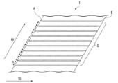
- FIG. 4A to 4C are diagrams showing examples of groove formation in the grain-oriented electrical steel sheet according to the embodiment
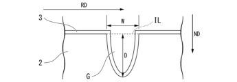
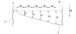
- FIG. 2 is a schematic diagram of a cross section of the grain-oriented electrical steel sheet according to the present embodiment, parallel to the rolling direction and the sheet thickness direction, including a groove.
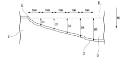
- FIG. 2 is a schematic diagram of a cross section of the grain-oriented electrical steel sheet according to the present embodiment, parallel to the sheet thickness direction and the groove extension direction, and passing through the center of the groove width.
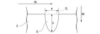
- FIG. 2 is a schematic diagram of a cross section parallel to the rolling direction and sheet thickness direction of the grain-oriented electrical steel sheet according to the present embodiment, including the grooves, after the insulating coating has been removed in order to measure the width and depth of the grooves.
- FIG. 1 is a schematic diagram of a cross section of the grain-oriented electrical steel sheet according to the present embodiment, parallel to the rolling direction and the sheet thickness direction, including a grooves, after the insulating coating has been removed in order to measure the width and depth of the groove
- FIG. 2 is a schematic diagram of a cross section of a grain-oriented electrical steel sheet according to this embodiment, parallel to the sheet thickness direction and the direction in which the grooves extend, and passing through the center of the groove width, after the insulating coating has been removed to measure the groove width and depth.
- This article describes a grain-oriented electromagnetic steel sheet according to one embodiment of the present invention (grain-oriented electromagnetic steel sheet according to this embodiment) and its manufacturing method.
- a grain-oriented electrical steel sheet 1 includes a base steel sheet 2 and an insulating coating 3 formed on the base steel sheet 2 .
- a forsterite film may be present between the base steel sheet 2 and the insulating film 3. That is, the steel sheet may include a base steel sheet 2, a forsterite film formed on the base steel sheet 2, and an insulating film 3 formed on the forsterite film.
- the base steel sheet 2 has a plurality of grooves extending in a direction intersecting the rolling direction. Each of the plurality of grooves has a predetermined shape, which will be described later, at the groove end portion, which is a region of 5 mm from the groove end E toward the center in the longitudinal direction of the groove. The details will be explained below.
- the direction in which the groove extends is the groove longitudinal direction.
- the distance from the imaginary line extending from the surface of the base steel plate to the groove (bottom of the groove) in the thickness direction of the base steel plate is the groove depth, and the width of the groove in the rolling direction is the groove width.
- the position where the groove depth is 0.0 ⁇ m is the groove end, and the area 5 mm from the groove end toward the center in the groove longitudinal direction is the groove end.
- the groove depth at a position 1 mm from the groove end in the groove longitudinal direction in the unit ⁇ m is D1, the groove width is W1, the groove depth at a position 2 mm from the groove end is D2, the groove width is W2, the groove depth at a position 3 mm from the groove end is D3, the groove width is W3, the groove depth at a position 4 mm from the groove end is D4, the groove width is W4, and the groove depth at a position 5 mm from the groove end is D5, and the groove width is W5. Furthermore, the average width of the groove at the center of the groove in the longitudinal direction is Wc, and the average depth of the groove is Dc.
- the groove end portion of the groove G formed in the base steel sheet 2 which is a region 5 mm from the groove end E (the position where the groove depth is 0.0 ⁇ m) toward the center in the longitudinal direction of the groove, the groove depth becomes shallower and the groove width narrower as it approaches the tip (end E) in the longitudinal direction of the groove, and the groove depth and groove width are shaped to satisfy a predetermined relationship, thereby improving the adhesion of the insulating coating.
- the groove depth becomes shallower and the groove width becomes narrower toward the end in the longitudinal direction of the groove.
- the width of the groove is narrower in portions where the groove depth is shallower.
- W0.05 and W0.50 preferably satisfy the formulas (3') and (4'), more preferably satisfy the formulas (5) and (6), and further preferably satisfy the formulas (5') and (6').
- the effect of further improving the adhesion of the insulating film can be obtained.
- the shape of the grooves other than the groove ends is not limited, but it is preferable that the average groove depth Dc at the center in the longitudinal direction of the groove is 5.0 to 40.0 ⁇ m and the average groove width Wc is 10.0 to 200.0 ⁇ m. By setting the range within this range, the effect of reducing iron loss due to magnetic domain refinement is increased.
- the intervals S between the multiple grooves G in the rolling direction RD are preferably 2 to 10 mm.
- the groove interval S is the distance from the center of a groove in the width direction to the center of an adjacent groove in the width direction.
- the intervals between the multiple grooves G do not have to be equal as long as they are within the above range, but are preferably equal.
- the angle between the direction in which the grooves extend (longitudinal direction of the grooves) and the rolling direction is preferably 60 to 120 degrees. Since the angle is preferably closer to a direction perpendicular to the rolling direction, the angle is more preferably 75 to 115 degrees with respect to the rolling direction.
- the grooves are preferably approximately parallel to each other.
- the cross section may be substantially rectangular or substantially triangular.
- the cross section may also be an arch shape that constitutes a part of a circle.
- the grooves extend in the width direction of the grain-oriented electromagnetic steel sheet and are linear.
- the grooves may be formed over the entire width of the grain-oriented electromagnetic steel sheet, or may be formed in only a portion of the width.
- the groove depth (D1 to D5) and groove width (W1 to W5) at the groove end are measured using a laser microscope (a 3D laser microscope using a pinhole confocal optical system). If the grain-oriented electrical steel sheet has an insulating coating, the groove depth and groove width are measured on the surface of the base steel sheet excluding the insulating coating.
- the insulating film of the grain-oriented electrical steel sheet can be removed by, for example, the following method: The grain-oriented electrical steel sheet having the insulating film is immersed in an aqueous sodium hydroxide solution of 30% by mass of NaOH and 70% by mass of H2O at 80°C for 20 minutes, and then rinsed with water. Finally, the sheet is dried for 1 minute with a hot air blower.
- a measured profile curve that defines the contour of the groove is obtained by measurement using a laser microscope in a cross section that is parallel to the plate thickness direction and the groove extension direction and passes through the center of the groove width.
- a low-pass filter with a cutoff value ⁇ s is applied to this measured profile curve to obtain a profile curve, and bandpass filters with cutoff values ⁇ f and ⁇ c are then applied to the profile curve to remove long wavelength components and short wavelength components from the profile curve.
- a waviness curve WCL that defines the contour of the groove in a cross section that is parallel to the plate thickness direction and the groove extension direction and passes through the center of the groove width is obtained, as shown in FIG. 3B.
- a waviness curve is a type of profile curve that is suitable for simplifying the shape of the contour itself with a smooth line.
- an imaginary line IL is drawn in the extension direction of the groove (left and right direction on the paper) extending from the surface of the base steel sheet, and the start point of the imaginary line IL, i.e., the position where the groove depth is 0.0 ⁇ m, is defined as the groove end E.
- the straight-line distance between the imaginary line IL and the base steel sheet 2 is obtained, and this is defined as the groove depth D1.
- a measured profile curve forming the contour of the groove in a cross section parallel to the rolling direction and the plate thickness direction is obtained by measurement using a laser microscope.
- a low-pass filter with a cutoff value ⁇ s is applied to this measured profile curve to obtain a profile curve, and then bandpass filters with cutoff values ⁇ f and ⁇ c are applied to the profile curve to remove long wavelength components and short wavelength components from the profile curve, thereby obtaining a waviness curve WCT forming the contour of the groove in a cross section parallel to the rolling direction and the plate thickness direction, as shown in Figure 3A.
- groove depths D2, D3, D4, D5 and groove widths W2, W3, W4, W5 are determined at positions 2 mm, 3 mm, 4 mm, and 5 mm from end E of the groove in the extension direction of the groove.
- the average groove depth Dc and average groove width Wc at the center of the groove length are measured using a laser microscope in the same manner as the groove depth and width at the groove ends.
- the groove depth and width are measured at five arbitrary points at the center of one groove length (within a range of center ⁇ 10 mm), and the respective average values are taken as the average groove depth Dc and average groove width Wc.
- the groove width W0.05 at a portion where the groove depth is 0.05 ⁇ Dc and the groove width W0.50 at a portion where the groove depth is 0.50 ⁇ Dc are measured using a laser microscope.
- the straight-line distance from the end E of the groove to the position where the groove depth is 0.05 ⁇ Dc and 0.50 ⁇ Dc is obtained from the waviness curve WCL that forms the contour of the groove in a cross section parallel to the thickness direction and the direction in which the groove extends and passing through the center of the width of the groove.
- a measured cross-sectional curve that forms the contour of the groove is obtained in a cross section parallel to the rolling direction and the thickness direction by measurement using a laser microscope.
- bandpass filters with cutoff values ⁇ f and ⁇ c are applied to the cross-sectional curve to remove long wavelength components and short wavelength components from the cross-sectional curve, and a waviness curve WCT of a cross section parallel to the rolling direction and the thickness direction is obtained.
- WCT the length of the virtual line IL extending in the rolling direction on the surface of the base steel sheet is obtained, and these are designated as W0.05 and W0.50.
- the grooves satisfy the formulas (1) to (4), and more preferably, the formulas (3') and (4'), or the formulas (5) and (6), or the formulas (5') and (6').
- the other grooves also satisfy the formulas (1) to (4).
- the groove end E does not exist at the end of that groove, and therefore the above-mentioned measurement is not performed (it is not considered as a groove to be measured).
- the chemical composition of the base steel sheet of the grain-oriented electrical steel sheet is not limited, and may be the same as that of the base steel sheet of a known grain-oriented electrical steel sheet.
- the chemical composition may be, in mass %, Si: 2.50-4.50%, Mn: 0.010-0.150%, C: 0-0.085%, acid-soluble Al: 0-0.065%, N: 0-0.012%, Cr: 0-0.30%, Cu: 0-0.40%, P: 0-0.50%, Sn: 0-0.30%, Sb: 0-0.
- the chemical composition of the grain-oriented electrical steel sheet may be measured by a general analysis method for steel.
- the chemical composition may be measured using ICP-AES (Inductively Coupled Plasma-Atomic Emission Spectrometry).
- ICP-AES Inductively Coupled Plasma-Atomic Emission Spectrometry
- the chemical composition of the base steel sheet may be analyzed after removing the insulating film from the grain-oriented electrical steel sheet by the above-mentioned method, and then removing the forsterite film by a known method such as pickling.
- a test piece of 35 mm square (35 mm x 35 mm) is obtained from the center of the base steel sheet after removing the film as necessary, and the analysis can be performed using a Shimadzu ICPS-8100 (measuring device) or the like, under conditions based on a calibration curve created in advance.
- C and S which are difficult to measure using ICP-AES, can be measured using the combustion-infrared absorption method, and N can be measured using the inert gas fusion-thermal conductivity method.
- the thickness of the base steel sheet of the grain-oriented electrical steel sheet is not limited, but is preferably 0.15 to 0.30 mm. If the thickness of the base steel sheet exceeds 0.30 mm, classical eddy current loss increases, and iron loss increases. On the other hand, if the thickness is less than 0.15 mm, the rolling efficiency decreases, which is disadvantageous in terms of productivity and cost.
- the grain-oriented electrical steel sheet according to this embodiment may be composed of a base steel sheet and an insulating coating formed on the surface of the base steel sheet, but a forsterite coating may be formed on the surface of the base steel sheet. In that case, the insulating coating may be formed on the surface of the forsterite coating. That is, the grain-oriented electrical steel sheet according to this embodiment may be composed of a base steel sheet, a forsterite film formed on the base steel sheet, and an insulating film formed on the forsterite film. The forsterite film and the insulating film may be formed on one side or both sides.
- the forsterite film is an inorganic film mainly composed of magnesium silicate, and is formed by a reaction between an annealing separator containing magnesia (MgO) applied to the surface of the base steel sheet and the surface components of the base steel sheet during finish annealing, and has a composition derived from the components of the annealing separator and the base steel sheet (more specifically, a composition mainly composed of Mg 2 SiO 4 ).
- MgO magnesia
- the forsterite film may not be formed.
- the insulating coating has the function of imparting electrical insulation and tension to the grain-oriented electrical steel sheet.
- the insulating film By imparting tension to the grain-oriented electrical steel sheet, it is possible to facilitate magnetic domain wall motion in the grain-oriented electrical steel sheet, thereby reducing the iron loss of the grain-oriented electrical steel sheet.
- the insulating film also provides various other properties such as rust resistance, heat resistance, and slipperiness.
- the insulating coating may be a known coating formed, for example, by applying a coating solution containing phosphate and colloidal silica as main components to the surface of the base steel sheet or the forsterite coating, and baking the solution (treatment for forming an insulating coating).
- the grain-oriented electrical steel sheet according to this embodiment can obtain its effects as long as it has the above-mentioned characteristics regardless of the manufacturing method, but a manufacturing method including the following steps is preferable because it can be stably manufactured.
- a groove forming step of forming a plurality of grooves extending in a direction intersecting the rolling direction in a steel sheet at predetermined intervals in the rolling direction;
- a decarburization annealing step of performing decarburization annealing on the steel sheet after the groove forming step;
- III a finish annealing step of performing finish annealing on the steel sheet after the decarburization annealing step;
- An insulating film forming process in which an insulating film is formed on the steel plate (in some cases, a forsterite film is formed on the base steel plate) after the final annealing process to obtain a grain-oriented electrical steel plate having the base steel plate, a forsterite film formed on any of the
- the steel sheet to be subjected to the groove forming step is a cold-rolled steel sheet
- it can be manufactured by a manufacturing method including the following steps.
- an annealing separator mainly composed of MgO or Al 2 O 3 is generally applied before the final annealing.
- a forsterite (Mg 2 SiO 4 ) film layer is formed.
- the forsterite film may not be formed. Therefore, the annealing separator can be selected depending on whether or not the formation of a forsterite film is required.
- the chemical composition of the slab to be subjected to hot rolling may be determined according to the desired chemical composition of the grain-oriented electrical steel sheet, taking into consideration changes in the chemical composition in each process. For example, when obtaining the chemical composition of the base steel sheet of the grain-oriented electrical steel sheet according to the above-mentioned preferred embodiment, it is preferable to use a slab having the following chemical composition.
- the chemical composition of the slab is as follows, in mass %, Si: 2.50-4.50%, Mn: 0.010-0.150%, C: 0.020-0.100%, acid-soluble Al: 0-0.065%, N: 0.002-0.030%, Cr: 0-0.30%, Cu: 0-0.40%, P: 0-0.50%, Sn: 0-0.30%, Sb: 0-0.50%, and Mn: 0-0.50%.
- Ni 0-1.00%
- S 0.001-0.050%
- Se 0-0.050%
- Bi 0-0.10%
- Nb 0-0.10%
- V 0-0.10%
- Mo 0-0.10%
- Ta 0-0.10%
- W 0-0.10%
- B 0-0.080%
- Ti 0-0.10%.
- the above may be contained, with the balance being Fe and impurities.
- a plurality of grooves extending in a direction intersecting the rolling direction are formed at predetermined intervals in a steel plate such as a hot-rolled steel plate or a cold-rolled steel plate.
- the grooves extending in a direction intersecting the rolling direction can be formed by irradiating the surface with a laser while scanning the surface in a direction intersecting the rolling direction.
- a plurality of grooves are formed at predetermined intervals in the rolling direction by repeatedly shifting the area scanned with the laser light at predetermined intervals in the rolling direction.
- the distance between the focus of the laser and the surface of the base steel plate is changed at the groove end depending on the distance from the end of the groove, so that D1, D2, D3, D4, D5, W1, W2, W3, W4 and W5 satisfy the following formulas (1) and (2), and the groove width at the groove end where the groove depth is 0.05 x Dc is W0.05 and the groove width at the groove end where the groove depth is 0.50 x Dc is W0.50, so that W0.05 and W0.50 satisfy the following formulas (3) and (4).
- the groove is formed so that W0.05 and W0.50 satisfy the following formulas (3') and (4'), the following formulas (5) and (6), or the following formulas (5') and (6').
- Forming grooves that satisfy formulas (1) to (4) improves the adhesion of an insulating coating formed in a subsequent process, making it possible to produce a grain-oriented electrical steel sheet with excellent adhesion of the insulating coating.
- D5 ⁇ D4 ⁇ D3 ⁇ D2 ⁇ D1 W5 ⁇ W4 ⁇ W3 ⁇ W2 ⁇ W1...(2) 0.004 ⁇ W0.05/Wc ⁇ 0.210...(3) 0.180 ⁇ W0.50/Wc ⁇ 0.810...(4) 0.005 ⁇ W0.05/Wc ⁇ 0.200...(3') 0.200 ⁇ W0.50/Wc ⁇ 0.800...(4') 0.008 ⁇ W0.05/Wc ⁇ 0.160...(5) 0.380 ⁇ W0.50/Wc ⁇ 0.710...(6) 0.010 ⁇ W0.05/Wc ⁇ 0.150...(5') 0.400 ⁇ W0.50/Wc ⁇ 0.700...(6')
- the laser focus When forming a groove by laser irradiation, the laser focus is moved away from the surface of the steel sheet, so that the laser energy on the surface of the steel sheet is reduced, and the depth of the groove is shallow and the width of the groove is narrow. Therefore, the distance between the laser focus and the surface of the base steel sheet is changed according to the distance from the end of the groove. That is, at the start of the laser irradiation of one groove, the laser focus is set to a position away from the surface of the steel sheet, and the focus is gradually moved to match the surface of the steel sheet as the scanning proceeds, so that the depth and width of the groove can be changed within a certain range from the start point of the groove.
- the laser focus is moved to a position away from the surface of the steel sheet, so that the depth and width of the groove can be changed within a certain range from the end point of the groove.
- the depth and width of the groove can also be changed by changing the laser output, the focal spot diameter, and the scanning speed. Since the groove depth and groove width can be changed independently by changing the conditions, each condition is set in combination so that the groove depth and groove width satisfy the formulas (1) to (4).
- Methods for moving the focal point of the laser include displacing the position of an optical component.
- the laser irradiation conditions are not limited, but in areas other than the groove ends, it is preferable that the laser output is 200 to 3000 W, the focused spot diameter, which is a diameter including 86% of the laser output in the rolling direction, is 10 to 1000 ⁇ m, the focused spot diameter in the plate width direction of the laser is 10 to 1000 ⁇ m, and the scanning speed is 2 to 50 m/s. In this case, it becomes easy to form grooves whose Dc and Wc fall within the preferred ranges.
- the groove forming step it is preferable to form the grooves so that the intervals between the multiple grooves in the rolling direction are each 2 to 10 mm, and the angle between the groove longitudinal direction and the rolling direction is 60 to 120 degrees (°). In this case, the iron loss reduction effect is large.
- This hot-rolled steel sheet was annealed by heating to 1100° C. and holding for 1 minute.
- the hot-rolled steel sheet after annealing was pickled and cold-rolled to obtain a cold-rolled steel sheet having a thickness of 0.22 mm.
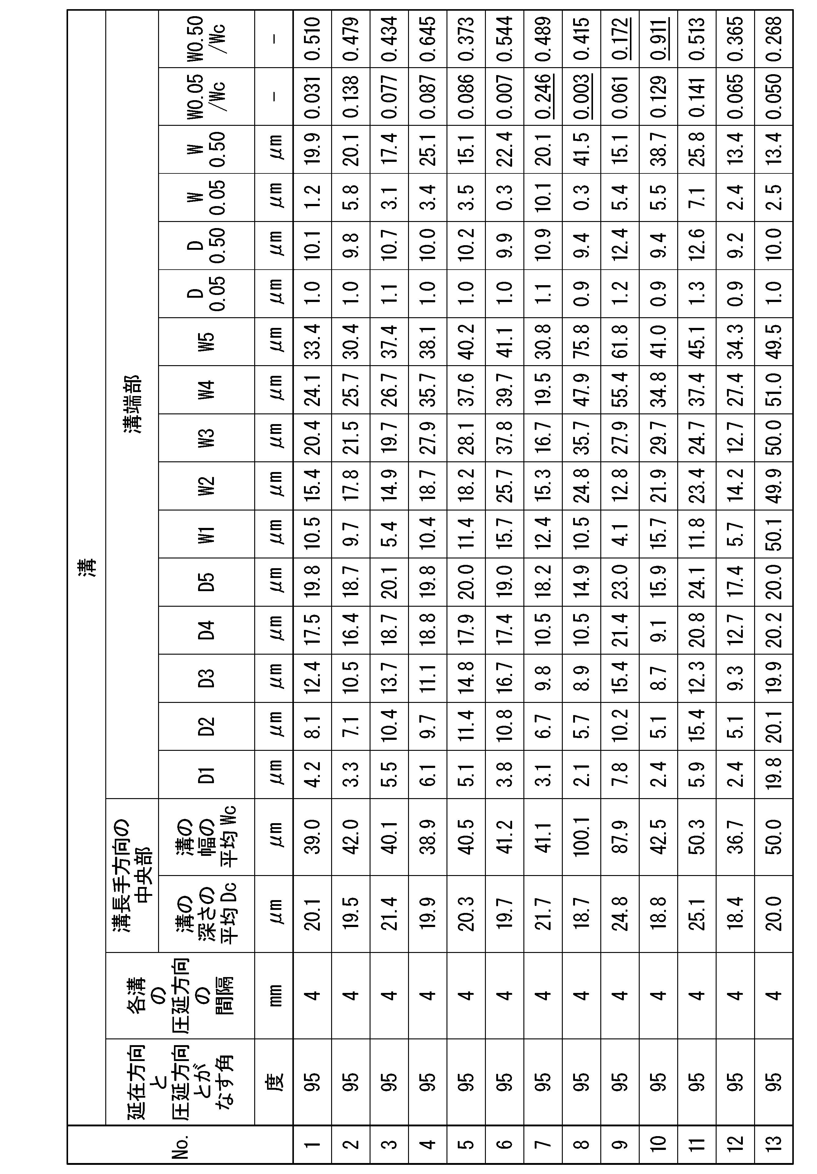
- the obtained cold-rolled steel sheets were irradiated with a laser under various conditions shown in Table 1 for each No. to form a plurality of grooves (the laser irradiation conditions were the same within one cold-rolled steel sheet).
- the groove ends were gradually changed in depth and width by displacing the position of the polygon mirror.
- the cold-rolled steel sheet after the groove formation was subjected to decarburization annealing under the conditions of heating to 850° C. and holding for 2 minutes.
- An annealing separator mainly composed of magnesia (MgO) was applied to the cold-rolled steel sheet after the decarburization annealing, and the steel sheet was subjected to finish annealing under the conditions of heating to 1200° C. and holding for 20 hours.
- MgO magnesia
- a steel sheet having a forsterite film formed on the surface of the cold-rolled steel sheet (base steel sheet) was obtained.
- a coating solution containing colloidal silica and aluminum phosphate was applied onto the forsterite film, and a heat treatment was performed under conditions of heating to 850° C. and holding for 1 minute to form an insulating film.
- the insulating film had a thickness of 5 ⁇ m.
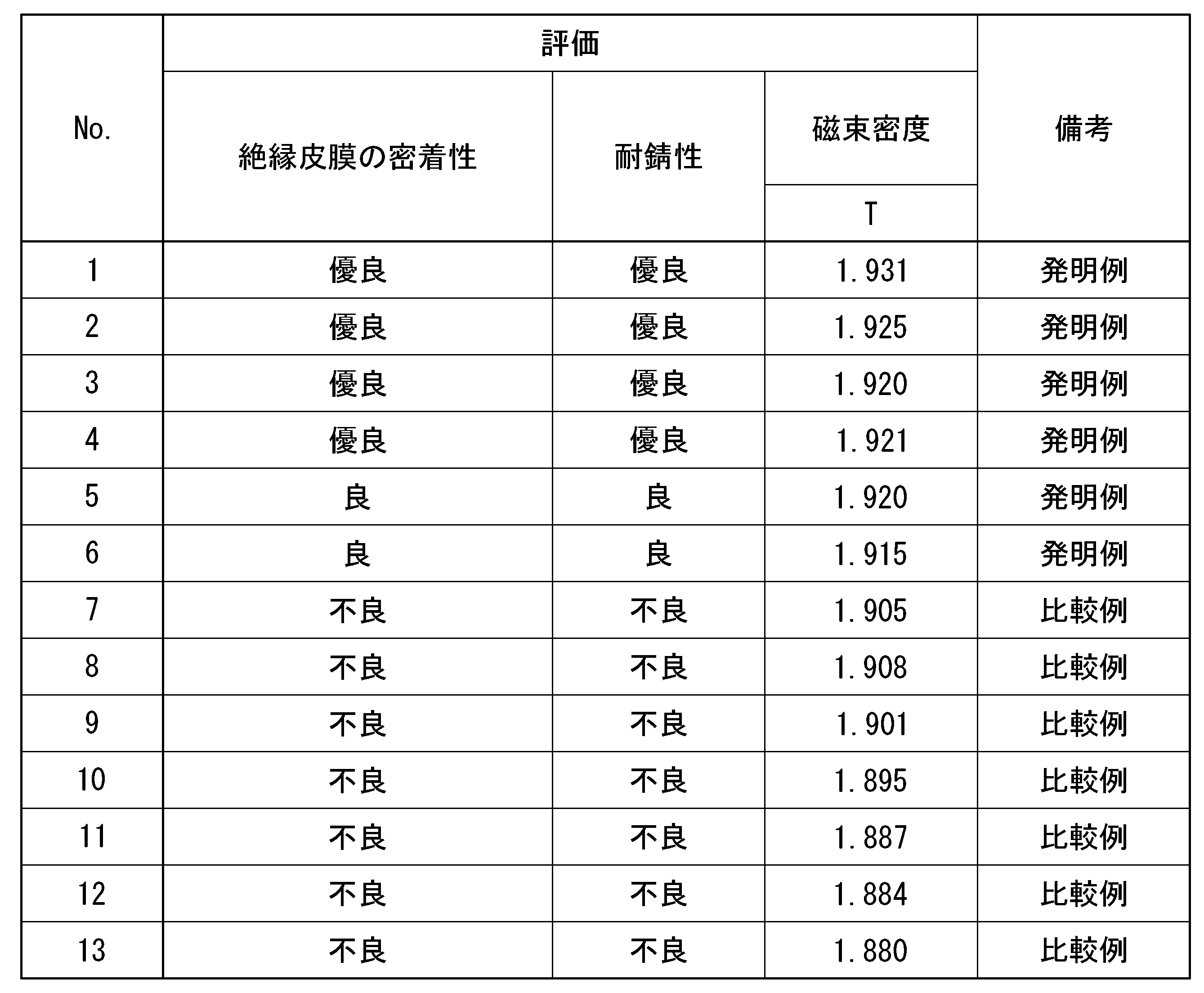
- a sample of 60 mm in the width direction and 300 mm in the rolling direction was taken from the obtained grain-oriented electrical steel sheet, and a single sheet magnetic property test (SST test) was performed on this sample in accordance with JIS C2556 (2015), and the magnetic flux density B8 generated when magnetized at 800 A/m was measured.
- a 30 mm x 30 mm test piece was taken from the obtained grain-oriented electrical steel sheet from a portion including the groove end, the insulating film was removed by the above-mentioned method, and then, for one representative groove, the average groove depth Dc at the center in the groove longitudinal direction, the average groove width Wc, the groove depths D1 to D5 at positions 1 mm to 5 mm from the groove end, and the groove widths W1 to W5 were measured by the above-mentioned method.
- the groove width W0.05 at the groove end where the groove depth was 0.05 x Dc, and the groove width W0.05 at the groove end where the groove depth was 0.50 x Dc were measured by the above-mentioned method. The results are shown in Table 2.
- a test piece of 80 mm x 80 mm was cut out from a portion including the end of the groove of the obtained grain-oriented electrical steel sheet, wrapped around a round bar of 20 mm in diameter, and then flattened. The surface of the test piece after being flattened was observed, and the area of the insulating coating that had not peeled off from the steel sheet relative to the area of the bent part was measured to calculate the remaining coating area ratio (%).
- the insulation coating adhesion of the test pieces with a coating remaining area ratio of 95% or more was evaluated as “excellent (Ex)”, the insulation coating adhesion of the test pieces with a coating remaining area ratio of 90% or more but less than 95% was evaluated as “good (G)”, and the insulation coating adhesion of the test pieces with a coating remaining area ratio of less than 90% was evaluated as “poor (P)”.
- the rust resistance of test pieces with a weight increase of 1.0 mg/m2 or less was evaluated as “excellent (Ex)”
- the rust resistance of test pieces with a weight increase of 5.0 mg/m2 or less was evaluated as “good (G)”
- the rust resistance of test pieces with a weight increase of more than 5.0 mg/ m2 was evaluated as “poor (P)”.
- the present invention it is possible to improve the rust resistance and adhesion of an insulating coating in a grain-oriented electrical steel sheet having grooves formed on the surface for the purpose of reducing iron loss. Therefore, by using the grain-oriented electrical steel sheet of the present invention, it is possible to prevent the occurrence of interlayer currents when steel sheets are stacked, which causes an increase in iron loss, and to prevent poor appearance.
Landscapes
- Chemical & Material Sciences (AREA)
- Engineering & Computer Science (AREA)
- Materials Engineering (AREA)
- Metallurgy (AREA)
- Organic Chemistry (AREA)
- Mechanical Engineering (AREA)
- Physics & Mathematics (AREA)
- Crystallography & Structural Chemistry (AREA)
- Thermal Sciences (AREA)
- Electromagnetism (AREA)
- Manufacturing & Machinery (AREA)
- Dispersion Chemistry (AREA)
- Power Engineering (AREA)
- Chemical Kinetics & Catalysis (AREA)
- General Chemical & Material Sciences (AREA)
- Soft Magnetic Materials (AREA)
- Manufacturing Of Steel Electrode Plates (AREA)
Abstract
Description
本願は、2023年07月06日に、日本に出願された特願2023-111726号に基づき優先権を主張し、その内容をここに援用する。
鉄損とは、鉄心を交流磁場で励磁した場合に、熱エネルギーとして消費される損失であり、省エネルギーの観点から、鉄損はできるだけ低いことが求められる。鉄損の高低には、磁化率、板厚、皮膜張力、不純物量、電気抵抗率、結晶粒径、磁区幅などが影響する。方向性電磁鋼板に関し、様々な技術が開発されている現在においても、エネルギー変換効率を高めるため、鉄損を低減する研究開発が継続されている。
鉄損を低減する方法の一つとして、鋼板にレーザ照射を行う技術が提案されている。この技術では、レーザ照射により鋼板の表面に歪が導入され、磁区幅が細分化されることで鉄損の一部である渦電流損を低減することができるとされている。
特許文献1では、容易に、かつ高い生産性を確保しながら、方向性電磁鋼板のL方向及びC方向の両方向における鉄損を低減することができることが示されている。
そのため、鋼板表面に溝を形成することによって、歪導入と同様に磁区幅を細分化し渦電流損を低減することが提案されている。このような場合、歪取焼鈍を行っても溝は消失しないため、磁区細分化の効果が消失することはない。
鋼板に溝を形成する方法には、例えば、電解エッチングによって方向性電磁鋼板の鋼板表面に溝を形成する電解エッチング法、機械的に歯車を方向性電磁鋼板の鋼板表面にプレスすることにより、鋼板表面に溝を形成する歯車プレス法、レーザ照射により鋼板(レーザ照射部)を溶融及び蒸発させて溝を形成するレーザ照射法が挙げられる。例えば、特許文献2には、レーザビームを制御して照射し、圧延方向幅0.5mm以下、深さ10μm以上の凹部を形成する、歪取焼鈍に耐え得る方向性電磁鋼板の鉄損特性を改善する方法が開示されている。
しかしながら、特許文献2では、このような地鉄の露出や錆の発生について検討されていない。
また、特許文献4では、溝端部における溝の幅及び深さに関しては何ら言及がなく、本発明者らが検討を行った結果、必ずしも溝端部における絶縁皮膜の密着性や耐錆性向上させることはできないことが分かった。
また、特許文献5では、溝端部における溝の幅に関しては何ら言及がなく、本発明者らが検討を行った結果、必ずしも溝端部における絶縁皮膜の密着性や耐錆性向上させることはできないことが分かった。また、必ずしも溝の形成による磁束密度の減少を抑制することはできないことが分かった。
そのため、本発明は、溝端部においても絶縁皮膜の密着性が高く、耐錆性に優れる方向性電磁鋼板を提供することを課題とする。
[1]本発明の一態様に係る方向性電磁鋼板は、母材鋼板と、任意に、母材鋼板上に形成されたフォルステライト皮膜と、前記母材鋼板上または前記フォルステライト皮膜上に形成された絶縁皮膜と、を備え、前記母材鋼板は、圧延方向と交差する方向に延在する溝を複数有し、前記溝の延在する方向を溝長手方向とし、前記溝の、前記母材鋼板の表面を延長した仮想線から前記母材鋼板の板厚方向に向かう直線の、前記仮想線から前記溝までの距離を、溝の深さとし、前記溝の、前記圧延方向の幅を、溝の幅とし、前記溝の深さが0.0μmとなる位置を、前記溝の端とし、前記溝の端から前記溝長手方向の中央部に向かって5mmの領域を溝端部とし、前記溝端部の前記溝長手方向の、単位μmでの、前記溝の端から1mmの位置における溝の深さをD1、溝の幅をW1とし、前記溝の端から2mmの位置における溝の深さをD2、溝の幅をW2とし、前記溝の端から3mmの位置における溝の深さをD3、溝の幅をW3とし、前記溝の端から4mmの位置における溝の深さをD4、溝の幅をW4とし、前記溝の端から5mmの位置における溝の深さをD5、溝の幅をW5とし、前記溝の、前記溝長手方向の中央部での溝の幅の平均をWc、溝の深さの平均をDcとしたとき、前記D1、前記D2、前記D3、前記D4、前記D5、前記W1、前記W2、前記W3、前記W4及び前記W5が、下記式(1)及び下記式(2)を満足し、前記溝端部において、前記溝の深さが0.05×Dcとなる部分の前記溝の幅をW0.05、前記溝の深さが0.50×Dcとなる部分の前記溝の幅をW0.50とするとき、W0.05とW0.50とが下記式(3)及び下記式(4)を満たす。
D5≧D4≧D3≧D2≧D1・・・(1)
W5≧W4≧W3≧W2≧W1・・・(2)
0.004≦W0.05/Wc≦0.210・・・(3)
0.180≦W0.50/Wc≦0.810・・・(4)
[2][1]に記載の方向性電磁鋼板は、前記W0.05と前記W0.50が、下記式(5)及び式(6)を満たしてもよい。
0.008≦W0.05/Wc≦0.160・・・(5)
0.380≦W0.50/Wc≦0.710・・・(6)
[3][1]に記載の方向性電磁鋼板は、前記D1、前記D2、前記D3、前記D4、前記D5が、下記式(1’)を満足してもよい。
D5>D4>D3>D2>D1・・・(1’)
[4][2]に記載の方向性電磁鋼板は、前記D1、前記D2、前記D3、前記D4、前記D5が、下記式(1’)を満足してもよい。
D5>D4>D3>D2>D1・・・(1’)
[5][1]~[4]のいずれか一項に記載の方向性電磁鋼板は、前記Dcが5.0~40.0μmであり、前記Wcが10.0~200.0μmであってもよい。
[6][1]~[4]のいずれか一項に記載の方向性電磁鋼板は、複数の前記溝の、前記圧延方向の間隔がそれぞれ2~10mmであり、前記溝長手方向と前記圧延方向とのなす角が60~120度であってもよい。
[7][5]に記載の方向性電磁鋼板は、複数の前記溝の、前記圧延方向の間隔がそれぞれ2~10mmであり、前記溝長手方向と前記圧延方向とのなす角が60~120度であってもよい。
[8]本発明の一態様に係る方向性電磁鋼板の製造方法は、鋼板に対し、圧延方向と交差する方向に走査しながらレーザを照射して前記圧延方向に延在する溝を形成する溝形成工程と、前記溝形成工程後の前記鋼板に脱炭焼鈍を行う脱炭焼鈍工程と、前記脱炭焼鈍工程後の前記鋼板に仕上げ焼鈍を行う仕上げ焼鈍工程と、母材鋼板となる前記仕上げ焼鈍工程後の前記鋼板に対し、絶縁皮膜を形成する処理を行って、前記母材鋼板と、前記母材鋼板上に任意に形成されたフォルステライト皮膜と、前記母材鋼板上または前記フォルステライト皮膜上に形成された前記絶縁皮膜とを有する方向性電磁鋼板を得る、絶縁皮膜形成工程と、を備え、前記溝形成工程では、前記溝の延在する方向を溝長手方向とし、前記溝の、前記母材鋼板の表面を延長した仮想線から前記母材鋼板の板厚方向に向かう直線の、前記仮想線から前記溝までの距離を、溝の深さとし、前記溝の、前記圧延方向の幅を、溝の幅とし、前記溝の深さが0.0μmとなる位置を、前記溝の端とし、前記溝の端から前記溝長手方向の中央部に向かって5mmの領域を溝端部とし、前記溝端部の前記溝長手方向の、単位μmでの、前記溝の端から1mmの位置における溝の深さをD1、溝の幅をW1とし、前記溝の端から2mmの位置における溝の深さをD2、溝の幅をW2とし、前記溝の端から3mmの位置における溝の深さをD3、溝の幅をW3とし、前記溝の端から4mmの位置における溝の深さをD4、溝の幅をW4とし、前記溝の端から5mmの位置における溝の深さをD5、溝の幅をW5とし、前記溝の、前記溝長手方向の中央部での溝の幅の平均をWc、溝の深さの平均をDcとしたとき、前記溝端部において、前記溝の端からの距離に応じて、レーザの焦点と前記母材鋼板の表面との距離を変化させることで、前記D1、前記D2、前記D3、前記D4、前記D5、前記W1、前記W2、前記W3、前記W4及び前記W5が、下記式(1)及び下記式(2)を満足するように、かつ、前記溝端部において、前記溝の深さが0.05×Dcとなる部分の前記溝の幅をW0.05、前記溝の深さが0.50×Dcとなる部分の前記溝の幅をW0.50とするとき、W0.05とW0.50とが下記式(3)及び下記式(4)を満たすように、前記レーザを照射して、前記溝を形成する。
D5≧D4≧D3≧D2≧D1・・・(1)
W5≧W4≧W3≧W2≧W1・・・(2)
0.004≦W0.05/Wc≦0.210・・・(3)
0.180≦W0.50/Wc≦0.810・・・(4)
[9][8]に記載の方向性電磁鋼板の製造方法では、前記溝形成工程では、前記W0.05と前記W0.50とが、下記式(5)及び式(6)を満たすように前記溝を形成してもよい。
0.008≦W0.05/Wc≦0.160・・・(5)
0.380≦W0.50/Wc≦0.710・・・(6)
[10][8]または[9]に記載の方向性電磁鋼板の製造方法では、前記溝形成工程では、前記レーザの照射条件として、前記レーザの出力を200~3000W、前記レーザの前記圧延方向における前記出力の86%を含む直径である集光スポット径を10~1000μm、前記レーザの板幅方向における前記集光スポット径を10~1000μm、走査速度を2~50m/sとし、前記Dcが5.0~40.0μm、前記Wcが10.0~200.0μmとなる前記溝を形成してもよい。
[11][8]または[9]に記載の方向性電磁鋼板の製造方法では、前記溝形成工程では、複数の前記溝の、前記圧延方向の間隔がそれぞれ2~10mmであり、前記溝長手方向と前記圧延方向とのなす角が60~120度となるように、前記溝を形成してもよい。
[12][10]に記載の方向性電磁鋼板の製造方法では、前記溝形成工程では、複数の前記溝の、前記圧延方向の間隔がそれぞれ2~10mmであり、前記溝長手方向と前記圧延方向とのなす角が60~120度となるように、前記溝を形成してもよい。
または、図には示さないが、母材鋼板2と絶縁皮膜3との間にフォルステライト皮膜を有していてもよい。すなわち、母材鋼板2と、母材鋼板2上に形成されたフォルステライト皮膜と、フォルステライト皮膜上に形成された絶縁皮膜3とを備えていてもよい。
本実施形態に係る方向性電磁鋼板1では、母材鋼板2は、圧延方向と交差する方向に延在する溝を複数有している。また、複数の溝は、溝の端Eから溝長手方向の中央部に向かって5mmの領域である溝端部において、いずれも後述する所定の形状を有している。
以下、詳細に説明する。
[母材鋼板]
(溝)
方向性電磁鋼板では鉄損の低減を目的として、鋼板の板幅方向と略平行に溝を形成する。一方、従来、溝長手方向の端部(始端付近及び終端付近)においては中央部と比較して幅や深さが変化し、絶縁皮膜の密着性が十分でない箇所が生じる場合があった。
これに対し、本実施形態に係る方向性電磁鋼板1では、母材鋼板2に形成された溝Gの、溝の端E(溝の深さが0.0μmとなる位置)から溝長手方向の中央部に向かって5mmの領域である溝端部において、溝長手方向の先端(端E)に近づくに従い溝の深さが浅く、溝の幅が狭くなり、溝の深さと溝の幅とが所定の関係を満足する形状にすることで、絶縁皮膜の密着性が向上する。
より具体的には、溝端部の溝の端から1~5mmの各位置での溝の深さD1~D5及び溝の幅W1~W5が、下記式(1)及び式(2)を満足し(ただしD5≠D1かつW5≠W1)、かつ、溝端部において、溝の深さが0.05×Dcとなる部分の溝の幅をW0.05、溝の深さが0.50×Dcとなる部分の溝の幅をW0.50とするとき、W0.05とW0.50とが下記式(3)及び下記式(4)を満たすことで、絶縁皮膜等の密着性が向上する。
D5≧D4≧D3≧D2≧D1・・・(1)
W5≧W4≧W3≧W2≧W1・・・(2)
0.004≦W0.05/Wc≦0.210・・・(3)
0.180≦W0.50/Wc≦0.810・・・(4)
式(1)および/または式(2)を満たさない場合、溝長手方向の先端において溝の深さや幅が急に変化し、その領域においてコーティング溶液を塗布し難くなるため、絶縁皮膜の密着性が低下すると考えられる。
式(3)および/または式(4)を満たさない場合、すなわち、溝端部において、溝の深さの変化の度合いと、溝の幅の変化の度合いとが大きく異なる場合、溝の幅は狭いが溝の深さが深い領域が存在し、その領域においてコーティング溶液を塗布し難くなるため、絶縁皮膜の密着性が低下すると考えられる。
0.005≦W0.05/Wc≦0.200・・・(3’)
0.200≦W0.50/Wc≦0.800・・・(4’)
0.008≦W0.05/Wc≦0.160・・・(5)
0.380≦W0.50/Wc≦0.710・・・(6)
0.010≦W0.05/Wc≦0.150・・・(5’)
0.400≦W0.50/Wc≦0.700・・・(6’)
この場合、さらに絶縁皮膜の密着性が向上する効果が得られる。
この範囲とすることで、磁区細分化による鉄損低減効果が大きくなる。
また、溝が延在する方向(溝長手方向)と圧延方向とのなす角が60~120度であることが好ましい。圧延方向に対して直交する方向に近い方が好ましいので、より好ましくは圧延方向に対して75~115度である。複数の溝はそれぞれが略平行であることが好ましい。
溝の延在方向および間隔が上記の範囲にある場合、鉄損低減効果が大きくなる。溝の形状は、限定されず、例えば断面が、略矩形状または略三角形である。また、断面が、円の一部を構成する弓型などであってもよい。
具体的には、まず、方向性電磁鋼板の絶縁皮膜は、例えば、次の方法によって除去することができる。絶縁皮膜を有する方向性電磁鋼板を、NaOH:30質量%+H2O:70質量%からなる80℃の水酸化ナトリウム水溶液に、20分間浸漬した後、水洗する。最後に、温風のブロアーで1分間乾燥させる。
上記の要領で絶縁皮膜を除去した後、レーザ顕微鏡を用いた測定により、板厚方向及び溝の延在する方向に平行でかつ溝の幅の中心を通る断面において、溝の輪郭を成す測定断面曲線を得る。この測定断面曲線にカットオフ値λsの低域フィルタを適用して断面曲線を得た後、その断面曲線にカットオフ値λfとλcの帯域フィルタを適用して、断面曲線から長い波長成分と短い波長成分を除去する。これにより、図3Bに示すように、板厚方向及び溝の延在する方向に平行でかつ溝の幅の中心を通る断面における溝の輪郭を成すうねり曲線WCLが得られる。うねり曲線は、輪郭の形状そのものを滑らかな線で単純化するのに適した輪郭曲線の一種である。
前記うねり曲線WCLおいて、母材鋼板の表面を延長した溝の延在方向(紙面では左右方向)に仮想線ILを引き、仮想線ILの始点、すなわち溝の深さが0.0μmとなる位置を、溝の端Eとする。溝の端Eから溝の延在方向(紙面では右方向)に1mmの位置において、仮想線ILと、母材鋼板2との直線距離を求め、これを溝の深さD1とする。
また、溝の深さD1を求めた位置において、レーザ顕微鏡を用いた測定により、圧延方向及び板厚方向に平行な断面において、溝の輪郭を成す測定断面曲線を得る。この測定断面曲線にカットオフ値λsの低域フィルタを適用して断面曲線を得た後、その断面曲線にカットオフ値λfとλcの帯域フィルタを適用して、断面曲線から長い波長成分と短い波長成分を除去すると、図3Aに示すように、圧延方向及び板厚方向に平行な断面における溝の輪郭を成すうねり曲線WCTが得られる。うねり曲線WCTにおいて、母材鋼板の表面を圧延方向に延長した仮想線ILの長さを求め、これを溝の幅W1とする。
同様の要領で、溝の端Eから溝の延在方向に2mm、3mm、4mm、5mmの位置で、溝の深さD2、D3、D4、D5、溝の幅W2、W3、W4、W5を、それぞれ求める。
図3Bに示すような、板厚方向及び溝の延在する方向に平行でかつ溝の幅の中心を通る断面において溝の輪郭を成すうねり曲線WCLより、溝の深さが0.05×Dc、0.50×Dcとなる位置の、溝の端Eからの直線距離を求める。それぞれの位置において、レーザ顕微鏡を用いた測定により、圧延方向及び板厚方向に平行な断面において、溝の輪郭を成す測定断面曲線を得る。この測定断面曲線にカットオフ値λsの低域フィルタを適用して断面曲線を得た後、その断面曲線にカットオフ値λfとλcの帯域フィルタを適用して、断面曲線から長い波長成分と短い波長成分を除去すると、圧延方向及び板厚方向に平行な断面のうねり曲線WCTが得られる。それぞれのうねり曲線WCT上において、母材鋼板の表面を圧延方向に延長した仮想線ILの長さを求め、これらをW0.05、W0.50とする。
同条件で、圧延方向に等間隔で繰り返し溝を形成する場合には、1本の溝が、式(1)~(4)を満足していれば、その他の溝についても、式(1)~(4)を満足すると考えられる。但し、母材鋼板の板幅の端まで溝が形成されている場合は、その溝の端部に溝の端Eが存在しないことになるため、上述の測定を行わない(測定対象の溝としない)。
方向性電磁鋼板の母材鋼板の化学組成は限定されず、公知の方向性電磁鋼板の母材鋼板と同等であればよい。例えば、化学組成として、質量%で、Si:2.50~4.50%、Mn:0.010~0.150%、C:0~0.085%、酸可溶性Al:0~0.065%、N:0~0.012%、Cr:0~0.30%、Cu:0~0.40%、P:0~0.50%、Sn:0~0.30%、Sb:0~0.30%、Ni:0~1.00%、S:0~0.015%、Se:0~0.015%、Bi:0~0.10%、Nb:0~0.10%、V:0~0.10%、Mo:0~0.10%、Ta:0~0.10%、W:0~0.10%、B:0~0.080%、Ti:0~0.10%を含有することができる。また、上記を含有し、残部がFe及び不純物であってもよい。
方向性電磁鋼板の母材鋼板の板厚は、限定されないが、0.15~0.30mmであることが好ましい。母材鋼板の板厚が0.30mmを超えると古典的渦電流損が大きくなり、鉄損が増大する。一方、板厚が0.15mmよりも小さいと圧延効率が低下し、生産性、コストの点で不利である。
[絶縁皮膜]
本実施形態に係る方向性電磁鋼板は、母材鋼板と、母材鋼板の表面に形成された絶縁皮膜とからなっていてもよいが、母材鋼板の表面に、フォルステライト皮膜が形成されていてもよい。その場合、絶縁皮膜はフォルステライト皮膜の表面に形成されていてもよい。
すなわち、本実施形態に係る方向性電磁鋼板は、母材鋼板と母材鋼板上に形成されたフォルステライト皮膜とフォルステライト皮膜上に形成された絶縁皮膜とからなっていてもよい。
フォルステライト皮膜及び絶縁皮膜は片面に形成されていてもよいが、両面に形成されていてもよい。
フォルステライト皮膜は、ケイ酸マグネシウムを主成分とする無機質の皮膜である。フォルステライト皮膜は、仕上げ焼鈍において、母材鋼板の表面に塗布されたマグネシア(MgO)を含む焼鈍分離剤と母材鋼板の表面の成分とが反応することにより形成され、焼鈍分離剤及び母材鋼板の成分に由来する組成(より詳細には、Mg2SiO4を主成分とする組成)を有する。
一方、仕上げ焼鈍において、Al2O3を主体とする焼鈍分離剤を用いた場合には、フォルステライト皮膜は形成されない場合がある。
絶縁皮膜は、方向性電磁鋼板に電気的絶縁性や張力を付与するという機能を有する。方向性電磁鋼板に張力を付与して、方向性電磁鋼板における磁壁移動を容易にすることで、方向性電磁鋼板の鉄損を低減することができる。
また、絶縁皮膜によれば、上記のような電気的絶縁性や張力以外にも、耐錆性、耐熱性、すべり性といった種々の特性が得られる。
本実施形態に係る方向性電磁鋼板では、絶縁皮膜は、例えば、リン酸塩とコロイダルシリカとを主成分とするコーティング溶液を母材鋼板またはフォルステライト皮膜の表面に塗布し、焼付けること(絶縁皮膜を形成する処理)によって形成される公知の皮膜であってよい。
本実施形態に係る方向性電磁鋼板は、製造方法によらず上記の特徴を有していれば、その効果は得られるが、以下の工程を含む製造方法であれば安定して製造できるので好ましい。
(I)鋼板に対し、圧延方向と交差する方向に延在する溝を、前記圧延方向に所定の間隔で複数形成する溝形成工程と、
(II)前記溝形成工程後の前記鋼板に脱炭焼鈍を行う脱炭焼鈍工程と、
(III)前記脱炭焼鈍工程後の前記鋼板に仕上げ焼鈍を行う仕上げ焼鈍工程と、
(IV)母材鋼板となる前記仕上げ焼鈍工程後の前記鋼板(母材鋼板上にフォルステライト皮膜が形成されている場合もある)に対し、絶縁皮膜を形成する処理を行って、前記母材鋼板と、任意の前記母材鋼板上に形成されたフォルステライト皮膜と、前記母材鋼板上または前記フォルステライト皮膜上に形成された前記絶縁皮膜とを有する方向性電磁鋼板を得る、絶縁皮膜形成工程。
また、溝形成工程に供する鋼板は、鋼板が冷延鋼板の場合、以下の工程を含む製造方法によって製造可能である。
(V)スラブを、加熱して熱間圧延して熱延鋼板とする熱間圧延工程と、
(VI)前記熱間圧延工程後の前記熱延鋼板を焼鈍する熱延鋼板焼鈍工程と、
(VII)前記熱延鋼板焼鈍工程後の前記熱延鋼板を、酸洗し、冷間圧延して冷延鋼板とする冷間圧延工程。
ただし、仕上げ焼鈍工程では、一般に、主としてMgOやAl2O3からなる焼鈍分離剤を塗布してから仕上げ焼鈍を行う。例えば、MgOを主成分とする焼鈍分離剤を用いると、フォルステライト(Mg2SiO4)皮膜の層が形成される。Al2O3を主成分とする焼鈍分離剤を用いた場合、フォルステライト皮膜は形成されない場合がある。
そのため、フォルステライト皮膜の形成の要否に応じて、焼鈍分離剤を選定すればよい。
例えば、上述した好ましい本実施形態に係る方向性電磁鋼板の母材鋼板の化学組成を得る場合、以下の化学組成を有するスラブを用いることが好ましい。
すなわち、スラブは、化学組成として、質量%で、Si:2.50~4.50%、Mn:0.010~0.150%、C:0.020~0.100%、酸可溶性Al:0~0.065%、N:0.002~0.030%、Cr:0~0.30%、Cu:0~0.40%、P:0~0.50%、Sn:0~0.30%、Sb:0~0.30%、Ni:0~1.00%、S:0.001~0.050%、Se:0~0.050%、Bi:0~0.10%、Nb:0~0.10%、V:0~0.10%、Mo:0~0.10%、Ta:0~0.10%、W:0~0.10%、B:0~0.080%、Ti:0~0.10%を含有することができる。また、上記を含有し、残部がFe及び不純物であってもよい。
溝形成工程では、熱延鋼板や冷延鋼板などの鋼板に対し、圧延方向と交差する方向に延在する溝を、前記圧延方向に所定の間隔で複数形成する。圧延方向と交差する方向に延在する溝は、圧延方向と交差する方向に走査しながらレーザを照射することで形成することができる。また、レーザ光を走査する部分を圧延方向に所定の間隔でずらしながら繰り返すことで、圧延方向に所定の間隔で複数の溝が形成される。
溝形成の際、溝端部において、溝の端からの距離に応じて、レーザの焦点と母材鋼板の表面との距離を変化させることで、D1、D2、D3、D4、D5、W1、W2、W3、W4及びW5が、下記式(1)及び下記式(2)を満足するように、かつ、溝端部において、溝の深さが0.05×Dcとなる部分の溝の幅をW0.05、溝の深さが0.50×Dcとなる部分の溝の幅をW0.50とするとき、W0.05とW0.50とが下記式(3)及び下記式(4)を満たすように、レーザを照射して、溝を形成する。
好ましくは、W0.05とW0.50とが、下記式(3’)及び式(4’)、下記式(5)及び式(6)、または下記式(5’)及び式(6’)を満たすように前記溝を形成する。
式(1)~(4)を満足する溝を形成することで、後工程で形成する絶縁皮膜の密着性が向上し、絶縁皮膜の密着性に優れた方向性電磁鋼板を製造することができる。
D5≧D4≧D3≧D2≧D1・・・(1)
W5≧W4≧W3≧W2≧W1・・・(2)
0.004≦W0.05/Wc≦0.210・・・(3)
0.180≦W0.50/Wc≦0.810・・・(4)
0.005≦W0.05/Wc≦0.200・・・(3’)
0.200≦W0.50/Wc≦0.800・・・(4’)
0.008≦W0.05/Wc≦0.160・・・(5)
0.380≦W0.50/Wc≦0.710・・・(6)
0.010≦W0.05/Wc≦0.150・・・(5’)
0.400≦W0.50/Wc≦0.700・・・(6’)
レーザの焦点を、移動させる方法としては、光学部品の位置を変位させる方法などが挙げられる。
溝形成工程において、レーザの照射条件は限定されないが、溝端部以外の領域では、レーザの出力を200~3000W、レーザの前記圧延方向における前記出力の86%を含む直径である集光スポット径を10~1000μm、レーザの板幅方向における集光スポット径を10~1000μm、走査速度を2~50m/sとすることが好ましい。
この場合、Dc、Wcが好ましい範囲にある溝を形成することが容易となる。
この場合、鉄損低減効果が大きくなる。
この熱延鋼板を、1100℃に加熱し1分間保持する条件で、熱延鋼板焼鈍した。
熱延鋼板焼鈍後の熱延鋼板を、酸洗し、冷間圧延して厚さが0.22mmの冷延鋼板とした。
得られた冷延鋼板に対し、各No.ごとに、表1に示す種々の条件でレーザ照射し、複数の溝を形成した(1枚の冷延鋼板の中ではレーザ照射条件は同じとした)。溝の端部については、ポリゴンミラーの位置を変位させることで、溝の深さ、幅が徐々に変化するようにした。
溝形成後の冷延鋼板を、850℃に加熱し2分間保持する条件で脱炭焼鈍を行った。
脱炭焼鈍後の冷延鋼板に、マグネシア(MgO)を主成分とする焼鈍分離剤を塗布し、1200℃に加熱し、20時間保持する条件で仕上げ焼鈍を行った。その結果、冷延鋼板(母材鋼板)の表面にフォルステライト皮膜が形成された鋼板が得られた。
次に、フォルステライト皮膜の上に、コロイダルシリカ及びリン酸アルミニウムを含有するコーティング溶液を塗布し、850℃に加熱し1分間保持する条件で熱処理を実施することで絶縁皮膜を形成した。絶縁皮膜の厚みは5μmであった。
得られた方向性電磁鋼板から幅方向に60mm、圧延方向に300mmの試料を採取し、この試料に対し、JIS C2556(2015)に準拠して単板磁気特性試験(SST試験)を実施し、800A/mにて磁化した際に生じる磁束密度B8を測定した。
結果を表2に示す。
結果を表3に示す。
得られた方向性電磁鋼板の溝の端部を含む部分から、80mm×80mmの試験片を切り出して、直径20mmの丸棒に巻き付け、次いで、平らに伸ばした。
平らに伸ばした後の試験片表面を観察し、曲げ部の面積に対して鋼板から剥離していない絶縁皮膜の面積を測定して、皮膜残存面積率(%)を算出した。
皮膜残存面積率が95%以上となった試験片の絶縁皮膜密着性を“優良(Ex)”と評価し、皮膜残存面積率が90%以上95%未満となった試験片の絶縁皮膜密着性を“良(G)”と評価し、皮膜残存面積率が90%未満となった試験片の絶縁皮膜密着性を“不良(P)”と評価した。
得られた方向性電磁鋼板の溝の端部を含む部分から、30mm×30mmの試験片を採取し、その試験片を、温度50℃及び湿度91%の雰囲気中に1週間放置して、その前後における試験片の重量変化に基づいて評価した。錆が発生すると試験片の重量が増加するため、重量増加量が少ないものほど耐錆性が良いと判断した。
具体的には、重量増加量が1.0mg/m2以下の試験片の耐錆性を“優良(Ex)”と評価し、重量増加量が5.0mg/m2以下の試験片の耐錆性を“良(G)”と評価し、重量増加量が5.0mg/m2超の試験片の耐錆性を“不良(P)”と評価した。

2 母材鋼板
3 絶縁皮膜
G 溝
E 溝の端
D 溝の深さ(D1、D2、D3、D4、D5、Dcの総称)
W 溝の幅 (W1、W2、W3、W4、W5、Wcの総称)
IL 母材鋼板の表面を延長した仮想線
S 溝の間隔
RD 圧延方向
TD 板幅方向
ND 母材鋼板の板厚方向
Claims (12)
- 母材鋼板と、
任意に、母材鋼板上に形成されたフォルステライト皮膜と、
前記母材鋼板上または前記フォルステライト皮膜上に形成された絶縁皮膜と、
を備え、
前記母材鋼板は、圧延方向と交差する方向に延在する溝を複数有し、
前記溝の延在する方向を溝長手方向とし、
前記溝の、前記母材鋼板の表面を延長した仮想線から前記母材鋼板の板厚方向に向かう直線の、前記仮想線から前記溝までの距離を、溝の深さとし、
前記溝の、前記圧延方向の幅を、溝の幅とし、
前記溝の深さが0.0μmとなる位置を、前記溝の端とし、前記溝の端から前記溝長手方向の中央部に向かって5mmの領域を溝端部とし、
前記溝端部の前記溝長手方向の、単位μmでの、前記溝の端から1mmの位置における溝の深さをD1、溝の幅をW1とし、前記溝の端から2mmの位置における溝の深さをD2、溝の幅をW2とし、前記溝の端から3mmの位置における溝の深さをD3、溝の幅をW3とし、前記溝の端から4mmの位置における溝の深さをD4、溝の幅をW4とし、前記溝の端から5mmの位置における溝の深さをD5、溝の幅をW5とし、
前記溝の、前記溝長手方向の中央部での溝の幅の平均をWc、溝の深さの平均をDcとしたとき、
前記D1、前記D2、前記D3、前記D4、前記D5、前記W1、前記W2、前記W3、前記W4及び前記W5が、下記式(1)及び下記式(2)を満足し、
前記溝端部において、前記溝の深さが0.05×Dcとなる部分の前記溝の幅をW0.05、前記溝の深さが0.50×Dcとなる部分の前記溝の幅をW0.50とするとき、W0.05とW0.50とが下記式(3)及び下記式(4)を満たす、
ことを特徴とする、方向性電磁鋼板。
D5≧D4≧D3≧D2≧D1・・・(1)
W5≧W4≧W3≧W2≧W1・・・(2)
0.004≦W0.05/Wc≦0.210・・・(3)
0.180≦W0.50/Wc≦0.810・・・(4) - 前記W0.05と前記W0.50が、下記式(5)及び式(6)を満たす、
ことを特徴とする、請求項1に記載の方向性電磁鋼板。
0.008≦W0.05/Wc≦0.160・・・(5)
0.380≦W0.50/Wc≦0.710・・・(6) - 前記D1、前記D2、前記D3、前記D4、前記D5が、下記式(1’)を満足する、
ことを特徴とする、請求項1に記載の方向性電磁鋼板。
D5>D4>D3>D2>D1・・・(1’) - 前記D1、前記D2、前記D3、前記D4、前記D5が、下記式(1’)を満足する、
ことを特徴とする、請求項2に記載の方向性電磁鋼板。
D5>D4>D3>D2>D1・・・(1’) - 前記Dcが5.0~40.0μmであり、前記Wcが10.0~200.0μmであることを特徴とする、請求項1~4のいずれか一項に記載の方向性電磁鋼板。
- 複数の前記溝の、前記圧延方向の間隔がそれぞれ2~10mmであり、前記溝長手方向と前記圧延方向とのなす角が60~120度である、
ことを特徴とする、請求項1~4のいずれか一項に記載の方向性電磁鋼板。 - 複数の前記溝の、前記圧延方向の間隔がそれぞれ2~10mmであり、前記溝長手方向と前記圧延方向とのなす角が60~120度である、
ことを特徴とする、請求項5に記載の方向性電磁鋼板。 - 鋼板に対し、圧延方向と交差する方向に走査しながらレーザを照射して前記圧延方向に延在する溝を形成する溝形成工程と、
前記溝形成工程後の前記鋼板に脱炭焼鈍を行う脱炭焼鈍工程と、
前記脱炭焼鈍工程後の前記鋼板に仕上げ焼鈍を行う仕上げ焼鈍工程と、
母材鋼板となる前記仕上げ焼鈍工程後の前記鋼板に対し、絶縁皮膜を形成する処理を行って、前記母材鋼板と、前記母材鋼板上に任意に形成されたフォルステライト皮膜と、前記母材鋼板上または前記フォルステライト皮膜上に形成された前記絶縁皮膜とを有する方向性電磁鋼板を得る、絶縁皮膜形成工程と、
を備え、
前記溝形成工程では、
前記溝の延在する方向を溝長手方向とし、
前記溝の、前記母材鋼板の表面を延長した仮想線から前記母材鋼板の板厚方向に向かう直線の、前記仮想線から前記溝までの距離を、溝の深さとし、
前記溝の、前記圧延方向の幅を、溝の幅とし、
前記溝の深さが0.0μmとなる位置を、前記溝の端とし、前記溝の端から前記溝長手方向の中央部に向かって5mmの領域を溝端部とし、
前記溝端部の前記溝長手方向の、単位μmでの、前記溝の端から1mmの位置における溝の深さをD1、溝の幅をW1とし、前記溝の端から2mmの位置における溝の深さをD2、溝の幅をW2とし、前記溝の端から3mmの位置における溝の深さをD3、溝の幅をW3とし、前記溝の端から4mmの位置における溝の深さをD4、溝の幅をW4とし、前記溝の端から5mmの位置における溝の深さをD5、溝の幅をW5とし、
前記溝の、前記溝長手方向の中央部での溝の幅の平均をWc、溝の深さの平均をDcとしたとき、
前記溝端部において、前記溝の端からの距離に応じて、レーザの焦点と前記母材鋼板の表面との距離を変化させることで、前記D1、前記D2、前記D3、前記D4、前記D5、前記W1、前記W2、前記W3、前記W4及び前記W5が、下記式(1)及び下記式(2)を満足するように、かつ、
前記溝端部において、前記溝の深さが0.05×Dcとなる部分の前記溝の幅をW0.05、前記溝の深さが0.50×Dcとなる部分の前記溝の幅をW0.50とするとき、W0.05とW0.50とが下記式(3)及び下記式(4)を満たすように、
前記レーザを照射して、前記溝を形成する、
ことを特徴とする、方向性電磁鋼板の製造方法。
D5≧D4≧D3≧D2≧D1・・・(1)
W5≧W4≧W3≧W2≧W1・・・(2)
0.004≦W0.05/Wc≦0.210・・・(3)
0.180≦W0.50/Wc≦0.810・・・(4) - 前記溝形成工程では、前記W0.05と前記W0.50とが、下記式(5)及び式(6)を満たすように前記溝を形成する、
ことを特徴とする、請求項8に記載の方向性電磁鋼板の製造方法。
0.008≦W0.05/Wc≦0.160・・・(5)
0.380≦W0.50/Wc≦0.710・・・(6) - 前記溝形成工程では、前記レーザの照射条件として、前記レーザの出力を200~3000W、前記レーザの前記圧延方向における前記出力の86%を含む直径である集光スポット径を10~1000μm、前記レーザの板幅方向における前記集光スポット径を10~1000μm、走査速度を2~50m/sとし、
前記Dcが5.0~40.0μm、前記Wcが10.0~200.0μmとなる前記溝を形成する、
ことを特徴とする、請求項8または9に記載の方向性電磁鋼板の製造方法。 - 前記溝形成工程では、複数の前記溝の、前記圧延方向の間隔がそれぞれ2~10mmであり、前記溝長手方向と前記圧延方向とのなす角が60~120度となるように、前記溝を形成する、
ことを特徴とする、請求項8または9に記載の方向性電磁鋼板の製造方法。 - 前記溝形成工程では、複数の前記溝の、前記圧延方向の間隔がそれぞれ2~10mmであり、前記溝長手方向と前記圧延方向とのなす角が60~120度となるように、前記溝を形成する、
ことを特徴とする、請求項10に記載の方向性電磁鋼板の製造方法。
Priority Applications (4)
| Application Number | Priority Date | Filing Date | Title |
|---|---|---|---|
| CN202480042483.3A CN121399285A (zh) | 2023-07-06 | 2024-07-04 | 取向性电磁钢板及其制造方法 |
| JP2025526419A JP7817654B2 (ja) | 2023-07-06 | 2024-07-04 | 方向性電磁鋼板およびその製造方法 |
| EP24836110.7A EP4741523A1 (en) | 2023-07-06 | 2024-07-04 | Grain-oriented electromagnetic steel sheet and method for manufacturing same |
| KR1020267000348A KR20260018982A (ko) | 2023-07-06 | 2024-07-04 | 방향성 전자 강판 및 그 제조 방법 |
Applications Claiming Priority (2)
| Application Number | Priority Date | Filing Date | Title |
|---|---|---|---|
| JP2023111726 | 2023-07-06 | ||
| JP2023-111726 | 2023-07-06 |
Publications (1)
| Publication Number | Publication Date |
|---|---|
| WO2025009598A1 true WO2025009598A1 (ja) | 2025-01-09 |
Family
ID=94171608
Family Applications (1)
| Application Number | Title | Priority Date | Filing Date |
|---|---|---|---|
| PCT/JP2024/024295 Ceased WO2025009598A1 (ja) | 2023-07-06 | 2024-07-04 | 方向性電磁鋼板およびその製造方法 |
Country Status (5)
| Country | Link |
|---|---|
| EP (1) | EP4741523A1 (ja) |
| JP (1) | JP7817654B2 (ja) |
| KR (1) | KR20260018982A (ja) |
| CN (1) | CN121399285A (ja) |
| WO (1) | WO2025009598A1 (ja) |
Citations (9)
| Publication number | Priority date | Publication date | Assignee | Title |
|---|---|---|---|---|
| JPH0657335A (ja) | 1992-08-07 | 1994-03-01 | Nippon Steel Corp | パルスco2レーザを用いた方向性電磁鋼板の鉄損改善方法および装置 |
| JP4016431B2 (ja) | 1995-03-31 | 2007-12-05 | Jfeスチール株式会社 | 方向性けい素鋼帯の製造方法及び電解エッチング装置 |
| JP4669565B2 (ja) | 2007-12-12 | 2011-04-13 | 新日本製鐵株式会社 | レーザ光の照射により磁区が制御された方向性電磁鋼板の製造方法 |
| WO2016171124A1 (ja) * | 2015-04-20 | 2016-10-27 | 新日鐵住金株式会社 | 方向性電磁鋼板 |
| WO2016171129A1 (ja) * | 2015-04-20 | 2016-10-27 | 新日鐵住金株式会社 | 方向性電磁鋼板 |
| WO2016171117A1 (ja) * | 2015-04-20 | 2016-10-27 | 新日鐵住金株式会社 | 方向性電磁鋼板 |
| JP2022503782A (ja) | 2018-09-21 | 2022-01-12 | ポスコ | 方向性電磁鋼板およびその磁区微細化方法 |
| JP2023111726A (ja) | 2022-01-31 | 2023-08-10 | 東邦化学工業株式会社 | 洗浄剤組成物 |
| WO2024111630A1 (ja) * | 2022-11-22 | 2024-05-30 | 日本製鉄株式会社 | 方向性電磁鋼板 |
Family Cites Families (1)
| Publication number | Priority date | Publication date | Assignee | Title |
|---|---|---|---|---|
| FR3001323B1 (fr) * | 2013-01-21 | 2015-02-13 | Francois Arnaudon | Systeme de cheville pour bloquer une corde d'instrument de musique (a cordes) dans une mecanique d'accordage afin de faciliter le montage de la corde et d'empecher l'instrument de se desaccorder |
-
2024
- 2024-07-04 WO PCT/JP2024/024295 patent/WO2025009598A1/ja not_active Ceased
- 2024-07-04 CN CN202480042483.3A patent/CN121399285A/zh active Pending
- 2024-07-04 JP JP2025526419A patent/JP7817654B2/ja active Active
- 2024-07-04 KR KR1020267000348A patent/KR20260018982A/ko active Pending
- 2024-07-04 EP EP24836110.7A patent/EP4741523A1/en active Pending
Patent Citations (10)
| Publication number | Priority date | Publication date | Assignee | Title |
|---|---|---|---|---|
| JPH0657335A (ja) | 1992-08-07 | 1994-03-01 | Nippon Steel Corp | パルスco2レーザを用いた方向性電磁鋼板の鉄損改善方法および装置 |
| JP4016431B2 (ja) | 1995-03-31 | 2007-12-05 | Jfeスチール株式会社 | 方向性けい素鋼帯の製造方法及び電解エッチング装置 |
| JP4669565B2 (ja) | 2007-12-12 | 2011-04-13 | 新日本製鐵株式会社 | レーザ光の照射により磁区が制御された方向性電磁鋼板の製造方法 |
| WO2016171124A1 (ja) * | 2015-04-20 | 2016-10-27 | 新日鐵住金株式会社 | 方向性電磁鋼板 |
| WO2016171129A1 (ja) * | 2015-04-20 | 2016-10-27 | 新日鐵住金株式会社 | 方向性電磁鋼板 |
| WO2016171117A1 (ja) * | 2015-04-20 | 2016-10-27 | 新日鐵住金株式会社 | 方向性電磁鋼板 |
| JP6418322B2 (ja) | 2015-04-20 | 2018-11-07 | 新日鐵住金株式会社 | 方向性電磁鋼板 |
| JP2022503782A (ja) | 2018-09-21 | 2022-01-12 | ポスコ | 方向性電磁鋼板およびその磁区微細化方法 |
| JP2023111726A (ja) | 2022-01-31 | 2023-08-10 | 東邦化学工業株式会社 | 洗浄剤組成物 |
| WO2024111630A1 (ja) * | 2022-11-22 | 2024-05-30 | 日本製鉄株式会社 | 方向性電磁鋼板 |
Also Published As
| Publication number | Publication date |
|---|---|
| KR20260018982A (ko) | 2026-02-09 |
| JPWO2025009598A1 (ja) | 2025-01-09 |
| EP4741523A1 (en) | 2026-05-13 |
| JP7817654B2 (ja) | 2026-02-19 |
| CN121399285A (zh) | 2026-01-23 |
Similar Documents
| Publication | Publication Date | Title |
|---|---|---|
| RU2665666C2 (ru) | Лист из имеющей ориентированную зеренную структуру электротехнической стали, обладающий низкими потерями в сердечнике и низкой магнитострикцией | |
| JP7620552B2 (ja) | 方向性電磁鋼板およびその製造方法 | |
| JP7188458B2 (ja) | 方向性電磁鋼板およびその製造方法 | |
| RU2570591C1 (ru) | Текстурированный лист из электротехнической стали | |
| KR101530450B1 (ko) | 방향성 전기 강판 | |
| WO2016171117A1 (ja) | 方向性電磁鋼板 | |
| CN110300808A (zh) | 取向性电磁钢板 | |
| JP6838321B2 (ja) | 方向性電磁鋼板の製造方法、及び方向性電磁鋼板 | |
| WO2019065645A1 (ja) | 方向性電磁鋼板 | |
| WO2020162608A1 (ja) | 方向性電磁鋼板、方向性電磁鋼板の絶縁被膜形成方法、及び方向性電磁鋼板の製造方法 | |
| MX2012015155A (es) | Metodo para la produccion de chapa de acero magnetica de grano orientado. | |
| JP4192399B2 (ja) | 方向性電磁鋼板およびその製造方法 | |
| JP7712588B2 (ja) | 方向性電磁鋼板及びその製造方法 | |
| JP7817654B2 (ja) | 方向性電磁鋼板およびその製造方法 | |
| JPS6376819A (ja) | 低鉄損方向性電磁鋼板およびその製造方法 | |
| JP7799219B2 (ja) | 方向性電磁鋼板及びその製造方法 | |
| WO2016105055A1 (ko) | 방향성 전기강판 및 그 제조방법 | |
| JP2025523566A (ja) | 方向性ケイ素鋼およびその製造方法 | |
| JP7727244B2 (ja) | 方向性電磁鋼板及びその製造方法 | |
| RU2854669C2 (ru) | Лист анизотропной электротехнической стали и способ его производства | |
| JP7529055B2 (ja) | 方向性電磁鋼板およびその製造方法 | |
| JP7727245B2 (ja) | 方向性電磁鋼板 | |
| JP7601299B1 (ja) | 変圧器用鉄心および変圧器 | |
| JP7792057B2 (ja) | 方向性電磁鋼板およびその製造方法 | |
| RU2776382C1 (ru) | Лист анизотропной электротехнической стали и способ его производства |
Legal Events
| Date | Code | Title | Description |
|---|---|---|---|
| 121 | Ep: the epo has been informed by wipo that ep was designated in this application |
Ref document number: 24836110 Country of ref document: EP Kind code of ref document: A1 |
|
| WWE | Wipo information: entry into national phase |
Ref document number: 2025526419 Country of ref document: JP |
|
| WWE | Wipo information: entry into national phase |
Ref document number: 202517129197 Country of ref document: IN |
|
| ENP | Entry into the national phase |
Ref document number: 1020267000348 Country of ref document: KR Free format text: ST27 STATUS EVENT CODE: A-0-1-A10-A15-NAP-PA0105 (AS PROVIDED BY THE NATIONAL OFFICE) |
|
| REG | Reference to national code |
Ref country code: BR Ref legal event code: B01A Ref document number: 112025028913 Country of ref document: BR |
|
| WWE | Wipo information: entry into national phase |
Ref document number: 1020267000348 Country of ref document: KR |
|
| WWP | Wipo information: published in national office |
Ref document number: 202517129197 Country of ref document: IN |
|
| WWE | Wipo information: entry into national phase |
Ref document number: 2026100605 Country of ref document: RU Ref document number: 2024836110 Country of ref document: EP |
|
| NENP | Non-entry into the national phase |
Ref country code: DE |
|
| ENP | Entry into the national phase |
Ref document number: 2024836110 Country of ref document: EP Effective date: 20260206 |
|
| WWP | Wipo information: published in national office |
Ref document number: 1020267000348 Country of ref document: KR |
|
| WWP | Wipo information: published in national office |
Ref document number: 2026100605 Country of ref document: RU |
|
| WWP | Wipo information: published in national office |
Ref document number: 2024836110 Country of ref document: EP |