WO2025009547A1 - 位置ずれ防止具及び無針注射器 - Google Patents
位置ずれ防止具及び無針注射器 Download PDFInfo
- Publication number
- WO2025009547A1 WO2025009547A1 PCT/JP2024/024043 JP2024024043W WO2025009547A1 WO 2025009547 A1 WO2025009547 A1 WO 2025009547A1 JP 2024024043 W JP2024024043 W JP 2024024043W WO 2025009547 A1 WO2025009547 A1 WO 2025009547A1
- Authority
- WO
- WIPO (PCT)
- Prior art keywords
- injection
- syringe
- target area
- eyeball
- prevention device
- Prior art date
- Legal status (The legal status is an assumption and is not a legal conclusion. Google has not performed a legal analysis and makes no representation as to the accuracy of the status listed.)
- Ceased
Links
Images







Classifications
-
- A—HUMAN NECESSITIES
- A61—MEDICAL OR VETERINARY SCIENCE; HYGIENE
- A61F—FILTERS IMPLANTABLE INTO BLOOD VESSELS; PROSTHESES; DEVICES PROVIDING PATENCY TO, OR PREVENTING COLLAPSING OF, TUBULAR STRUCTURES OF THE BODY, e.g. STENTS; ORTHOPAEDIC, NURSING OR CONTRACEPTIVE DEVICES; FOMENTATION; TREATMENT OR PROTECTION OF EYES OR EARS; BANDAGES, DRESSINGS OR ABSORBENT PADS; FIRST-AID KITS
- A61F9/00—Methods or devices for treatment of the eyes; Devices for putting in contact-lenses; Devices to correct squinting; Apparatus to guide the blind; Protective devices for the eyes, carried on the body or in the hand
- A61F9/007—Methods or devices for eye surgery
-
- A—HUMAN NECESSITIES
- A61—MEDICAL OR VETERINARY SCIENCE; HYGIENE
- A61M—DEVICES FOR INTRODUCING MEDIA INTO, OR ONTO, THE BODY; DEVICES FOR TRANSDUCING BODY MEDIA OR FOR TAKING MEDIA FROM THE BODY; DEVICES FOR PRODUCING OR ENDING SLEEP OR STUPOR
- A61M5/00—Devices for bringing media into the body in a subcutaneous, intra-vascular or intramuscular way; Accessories therefor, e.g. filling or cleaning devices, arm-rests
- A61M5/178—Syringes
- A61M5/30—Syringes for injection by jet action, without needle, e.g. for use with replaceable ampoules or carpules
-
- A—HUMAN NECESSITIES
- A61—MEDICAL OR VETERINARY SCIENCE; HYGIENE
- A61M—DEVICES FOR INTRODUCING MEDIA INTO, OR ONTO, THE BODY; DEVICES FOR TRANSDUCING BODY MEDIA OR FOR TAKING MEDIA FROM THE BODY; DEVICES FOR PRODUCING OR ENDING SLEEP OR STUPOR
- A61M5/00—Devices for bringing media into the body in a subcutaneous, intra-vascular or intramuscular way; Accessories therefor, e.g. filling or cleaning devices, arm-rests
- A61M5/178—Syringes
- A61M5/31—Details
- A61M5/32—Needles; Details of needles pertaining to their connection with syringe or hub; Accessories for bringing the needle into, or holding the needle on, the body; Devices for protection of needles
Definitions
- the present invention relates to a device for preventing displacement and a needleless syringe.
- Patent document 1 discloses a device for delivering a drug into the eye, the device including a housing, at least one nozzle in a portion of the housing, a drug source within the housing, and an energy source that provides pressure to expel the drug out of the housing through the at least one nozzle.
- Patent Document 1 does not have a structure to prevent the injection position from shifting due to the patient's movement, for example, when injecting a drug into the patient. This poses the problem that lacerations can occur if the injection position shifts during drug injection.
- the technology disclosed herein has been developed in light of the above-mentioned circumstances, and aims to prevent the syringe from shifting relative to the target area of the eyeball.
- the displacement prevention device disclosed herein comprises: A positional deviation prevention device for suppressing deviation between a syringe that injects an injection objective substance from an injection part into a target area of an eyeball to be injected and the target area, A base body is arranged around an axis along the injection direction of the injection objective substance so as to surround the injection part; The substrate has an uneven portion provided on the target area side.
- the syringe may be a syringe that injects the injection objective substance into the target area without using an injection needle by injecting the injection objective substance from an injection port that is the injection part.
- the needleless syringe includes a storage section having a storage space in which the injection objective substance is stored and having the injection outlet through which the injection objective substance is injected into the target area,
- the substrate may be attached to the housing of the needle-free syringe.
- the needleless syringe includes a storage unit having a storage space for storing the injection objective substance and having the injection outlet through which the injection objective substance is injected into the target area, and a holding unit for holding the storage unit,
- the substrate may be attached to the holder of the needle-free syringe.
- the injection portion of the syringe includes a needle;
- the base may be disposed at a position surrounding the injection needle about its axis.
- the uneven portion may include a plurality of protrusions around the axis, and a contact surface of each protrusion that contacts the eyeball may be formed along a predetermined curved surface corresponding to the eyeball.
- the needleless syringe of the present disclosure comprises: A syringe that injects an injection objective substance from an injection part into a target area of an eyeball that is an injection target, a storage section having a storage space in which the injection objective substance is stored and having the injection section through which the injection objective substance is injected into the target area; a positional deviation prevention device for suppressing deviation of the needle-free syringe relative to the target area;
- the position shift prevention tool is A base body is arranged around an axis along the injection direction of the injection objective substance so as to surround the injection part;
- the substrate has an uneven portion provided on a surface thereof facing the target area.
- the syringe may be a needleless syringe that injects the injection target substance into the target area without using an injection needle by injecting the injection target substance from an injection port that is the injection section.
- the syringe may have a base attached to the housing of the needleless syringe.
- the syringe comprises: Further comprising a holding portion for holding the storage portion, The substrate may be attached to the holder of the needle-free syringe.
- the syringe comprises:
- the injection part includes a syringe needle;
- the base may be disposed at a position surrounding the injection needle about its axis.
- the uneven portion may have a plurality of protrusions around the axis, and the contact surface of each protrusion that contacts the eyeball may be formed along a predetermined curved surface that corresponds to the eyeball.
- the present disclosure makes it possible to prevent the syringe from shifting relative to the target area of the eyeball.
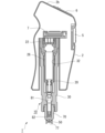
- FIG. 1 is a diagram showing a schematic external appearance of a syringe.
- FIG. 2 is a first cross-sectional view of the syringe, which cross-section is taken along line AA in FIG. 4 described below.
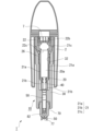
- FIG. 3 is a second cross-sectional view of the syringe, the cross-section being taken along line BB in FIG. 4 described below, the BB cross-section being perpendicular to the AA cross-section.
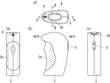
- FIG. 4 is a diagram showing the configuration of a housing that constitutes the syringe.
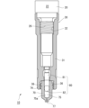
- FIG. 5 is a diagram showing a schematic configuration of a syringe assembly.
- FIG. 6 is a cross-sectional view showing a schematic configuration of a container.
- FIG. 1 is a diagram showing a schematic external appearance of a syringe.
- FIG. 2 is a first cross-sectional view of the syringe, which cross-section is taken along line AA in FIG. 4 described below
- FIG. 7 is an external view showing a schematic configuration of the container.
- FIG. 8 is a diagram showing a schematic configuration of the displacement prevention device, and is a diagram (side view) of the displacement prevention device as viewed from a direction perpendicular to the injection direction of the syringe.
- FIG. 9 is a cross-sectional view of FIG.
- FIG. 10 is a view of the displacement prevention device as seen from the tip side.
- FIG. 11 is a view of the displacement prevention device as seen from the base end side.
- FIG. 12 is a perspective view showing a schematic configuration of a displacement prevention device.
- FIG. 13 is a schematic diagram showing the positional relationship between the contact surface of the displacement prevention tool and the injection port.
- FIG. 14 is a diagram showing a schematic configuration of a displacement prevention device and a container according to the second embodiment.
- FIG. 15 is a diagram for explaining the positional relationship between a container and a container holder according to the second embodiment.
- FIG. 16 is a cross-sectional view showing a schematic configuration of a displacement prevention device and a container according to the third embodiment.
- FIG. 17 is a view of the displacement prevention device according to the third embodiment, as viewed from the tip side.
- FIG. 18 is a schematic diagram of a syringe according to the fourth embodiment.
- FIG. 19 is a diagram showing the tip side of a displacement prevention device according to the fourth embodiment.
- FIG. 20 is a diagram showing the base end side of a displacement prevention device according to the fourth embodiment.
- FIG. 21 is a schematic diagram of a syringe according to the fifth embodiment.
- FIG. 22 is a cross-sectional view of the tip end side of the syringe.
- the syringe 1 is a needleless syringe that uses the combustion energy of explosives to inject a liquid corresponding to the injection target substance of the present application into a target area, that is, a device that performs an injection by injecting the liquid into a target area without using an injection needle.
- the "tip side” refers to the position closer to the tip of the syringe 1, i.e., closer to the injection port 77, which will be described later
- the “base side” refers to the direction opposite to the "tip side” in the longitudinal direction of the syringe 1, i.e., the direction toward the igniter 22 in the syringe assembly 10 (see FIG. 5, which will be described later).
- Fig. 1 is a diagram showing a schematic appearance of a syringe 1.
- Fig. 2 is a first cross-sectional view of the syringe 1, which is a cross-section taken along line AA in Fig. 4 described later.
- Fig. 3 is a second cross-sectional view of the syringe 1, which is a cross-section taken along line BB in Fig. 4 described later, which is perpendicular to the cross-section AA.
- Fig. 4 is a diagram showing a configuration of a housing 2 constituting the syringe 1
- Fig. 5 is a diagram showing a schematic configuration of a syringe assembly 10.
- the syringe 1 is formed by attaching the syringe assembly 10 to the housing 2.
- a power cable 3 (Fig. 1) for supplying a drive current to an igniter 22 in the syringe assembly 10 is connected to the housing 2.
- the ejected liquid ejected into the target area by the syringe 1 is formed by containing a specific substance that exerts the efficacy or function expected in the target area in a liquid medium.
- the specific substance may be in a dissolved state in the liquid medium, or it may simply be in a mixed state without being dissolved.
- the specified substance contained in the injection liquid examples include biologically derived substances that can be injected into a target area that is a living organism, and substances that exhibit the desired physiological activity.
- biologically derived substances include DNA, RNA, nucleic acids, antibodies, cells, etc.
- biologically active substances include medicines made of low molecular weight molecules, proteins, peptides, etc., vaccines, inorganic substances such as metal particles for thermotherapy and radiotherapy, and substances with various pharmacological and therapeutic effects including carriers.
- the liquid medium for the injection liquid may be any substance suitable for administering these specified substances into the target area, and may be water-based or oil-based.
- there are no particular limitations on the viscosity of the liquid medium so long as the specified substance can be injected with the syringe 1.
- the syringe assembly 10 is configured to be detachable from the housing 2.
- a storage space 75 formed between a container (storage section) 70 and a plunger 80 included in the syringe assembly 10 is filled with the injection liquid in a preparation stage before the syringe 1 is actuated, and the syringe assembly 10 is a unit that is replaced each time the injection liquid is to be injected. Details of the syringe assembly 10 will be described later.
- the housing 2 is formed with a grip portion 2a that is held by the user of the syringe 1 for use, and is provided with a number of switches for operating the syringe 1 to realize the injection of the injection liquid.
- the syringe 1 is configured so that the user can hold it with one hand and operate it.
- FIG. 4 shows the appearance of the housing 2 when viewed from the front, (b) shows the appearance of the housing 2 when viewed from the side, (c) shows the appearance of the housing 2 when viewed from the rear, and (d) shows the appearance of the housing 2 when viewed from above.
- the "front” refers to the part located distal to the user when the user holds the housing 2, which is located on the left side in FIG. 4(b), and the “rear” refers to the part located proximal to the user, which is located on the right side in FIG. 4(b). Therefore, when the user holds the housing 2 with one hand, the fingertips are placed on the front of the housing 2, which is the distal side, and the wrist is in a state close to the rear of the housing 2, which is the proximal side. Additionally, “upper” refers to the area toward the base end of the syringe 1.
- a grip portion 2a is provided near the front of the housing 2 to make it easier for the user's fingertips to grip.
- Multiple dimples are formed in the grip portion 2a to improve the grip of the user's fingertips.
- the outer periphery on the front side of the grip portion 2a is gently uneven (see FIG. 4(b)), making it easier for the user's index finger and middle finger to grip it.
- the housing 2 is provided with a first switch 5 and a second switch 6, which are two operation switches for operating the syringe 1.
- the first switch 5 and the second switch 6 are connected to a control unit such as a microcomputer (not shown), and the control unit controls the supply of ignition current to the igniter 22 based on signals from each switch, thereby controlling the operation of the syringe 1.
- the first switch 5 is a sliding switch provided at the rear of the housing 2, and the sliding direction is the vertical direction of the housing 2 (the direction connecting the tip and the base end).
- the first switch 5 is constantly biased in the upward direction, and the user can bring the syringe 1 into a standby state by continuing to slide the first switch 5 downward (toward the tip) against the biasing force for a certain period of time.
- the standby state is a state in which the syringe 1 is ready to inject the injection liquid, and is a state in which injection is performed if the user performs additional operations.
- the second switch 6 is a push-down switch provided on the upper inclined surface 2b of the housing 2, and the user can push the second switch 6 inwardly of the housing 2.
- the control unit is configured to supply an ignition current to the igniter 22 by pushing the second switch 6.
- a connector 4 to which the power cable 3 is connected is provided in front of the upper inclined surface 2b of the housing 2.
- the connector 4 is a USB connector, and the power cable 3 is detachable from the housing 2.
- the power for operating the igniter 22 is supplied from the outside via the power cable 3.
- a battery for supplying the power may be provided inside the housing 2. In this case, as long as the battery has power remaining, the housing 2 can be used repeatedly while replacing the syringe assembly 10. When the battery runs out of power, the battery can be replaced.
- the schematic configuration of the syringe assembly 10 is shown in FIG. 5.
- the syringe assembly 10 is attached to the housing 2 to form the syringe 1.
- the syringe assembly 10 is an assembly including an actuator (drive unit) 20, an attachment 30, a displacement prevention device 50, a container 70, and a plunger 80. The assembly of the syringe assembly 10 will be described later.
- the actuator 20 has a body 21 formed in a cylindrical shape.
- the body 21 has a central portion 21a at its center, a tip portion 21b at its tip side, and a base end portion 21c at its base end side.
- the tip portion 21b, the central portion 21a, and the base end portion 21c are connected to each other in their internal spaces, and an opening 27 is provided at the tip side of the tip portion 21b.
- an igniter 22 which is an electric igniter that burns an ignition charge to generate ejection energy, is attached to the base end portion 21c of the body 21.
- the igniter 22 has an ignition pin 22b to which an ignition current is supplied from the outside, and this ignition pin 22b is connected to the socket 7 on the housing 2 side when the syringe assembly 10 is attached to the housing 2.
- the attachment state of the igniter 22 to the body 21 is determined so that the combustion products generated by the operation of the igniter 22 are released toward the central portion 21a of the body 21. That is, the igniter 22 is attached to the base end 21c of the body 21 so that the emission surface 22c of the combustion products faces the central portion 21a.
- the ignition charge is preferably an explosive containing zirconium and potassium perchlorate (ZPP), an explosive containing titanium hydride and potassium perchlorate (THPP), an explosive containing titanium and potassium perchlorate (TiPP), an explosive containing aluminum and potassium perchlorate (APP), an explosive containing aluminum and bismuth oxide (ABO), an explosive containing aluminum and molybdenum oxide (AMO), an explosive containing aluminum and copper oxide (ACO), an explosive containing aluminum and iron oxide (AFO), or an explosive consisting of a combination of these explosives.
- ZPP zirconium and potassium perchlorate
- THPP an explosive containing titanium hydride and potassium perchlorate
- TiPP an explosive containing titanium and potassium perchlorate
- APP explosive containing aluminum and potassium perchlorate
- ABO aluminum and bismuth oxide
- AMO explosive containing aluminum and molybdenum oxide
- ACO explosive containing aluminum and copper oxide
- AFO explosive containing aluminum and iron oxide
- the body 21 is a cylindrical member, and the internal space of the central portion 21a is the combustion chamber 20a. Furthermore, a male thread portion 26 is formed on a part of the outer surface of the central portion 21a. The male thread portion 26 is configured to screw into the female thread portion 32 of the attachment 30 described below, and the effective lengths of the male thread portion 26 and the female thread portion 32 are determined so as to ensure the necessary bonding force between the two.
- the internal space of the tip portion 21b adjacent to the central portion 21a is formed cylindrical, and a piston 40 is arranged therein so as to be able to slide.
- the actuator 20 has a mechanism in which the igniter 22 is the actuation source and the piston 40 is the output section.
- the attachment 30 is a part for attaching the actuator 20, plunger 80, and container 70 as shown in FIG. 5.
- the body 31 of the attachment 30 can be made of known resins such as nylon 6-12, polyarylate, polybutylene terephthalate, polyphenylene sulfide, or liquid crystal polymer. These resins can also contain fillers such as glass fiber or glass filler. Polybutylene terephthalate can contain 20 to 80% by mass of glass fiber, polyphenylene sulfide can contain 20 to 80% by mass of glass fiber, and liquid crystal polymer can contain 20 to 80% by mass of minerals.
- the material of the attachment 30 is not limited to resin, but can also be metal or ceramic.
- the actuator 20 is disposed in the internal space of the body 31 from the base end to the center.
- the base end 21c of the actuator 20 is generally located in the base end region
- the center 21a and tip 21b of the actuator 20 are generally located in the tip end region, which has a smaller diameter than the base end.
- a female thread 32 is disposed on the inner wall surface of the body 31, and the female thread 32 is formed to screw into the male thread 26 provided in the center 21a of the actuator 20.
- a plunger 80 is generally disposed in a region on the tip side of the region in which the actuator 20 is disposed, as shown in FIG. 5.
- the diameter of the region in which the plunger 80 is disposed is smaller than the diameter of the region in which the tip portion 21b of the actuator 20 is disposed, and is a diameter that allows the plunger 80 to slide.
- a portion of the container 70 is generally placed in the area on the tip side.
- the area in which the container 70 is placed communicates with the area in which the plunger 80 is placed at its base end, and the tip side opens into the tip surface of the attachment 30.
- a female threaded portion 36 for attaching the container 70 is formed on the inner wall of the area in which the container 70 is placed.
- the female threaded portion 36 screws into the male threaded portion 74 of the container 70 shown in Figures 6 and 7 described below, thereby realizing the connection between the attachment 30 and the container 70.
- the plunger 80 is a member that pressurizes the liquid to be ejected by the energy received from the piston 40, and has a plunger rod 81 and a stopper portion 82.
- the plunger rod 81 is formed, for example, from a resin material suitable for pressurization, but is not limited thereto and may be formed, for example, from the same type of material as the attachment 30.
- a stopper portion 82 made of an elastic material such as rubber is attached to the tip side of the plunger rod 81.
- Specific materials that can be used for the stopper portion 82 include, for example, butyl rubber and silicone rubber.
- Other examples include styrene-based elastomers, hydrogenated styrene-based elastomers, and mixtures of these with polyolefins such as polyethylene, polypropylene, polybutene, and ⁇ -olefin copolymers, oils such as liquid para and process oil, and powdered inorganic materials such as talc, cast, and mica.
- various rubber materials such as polyvinyl chloride-based elastomers, olefin-based elastomers, polyester-based elastomers, polyamide-based elastomers, polyurethane-based elastomers, natural rubber, isoprene rubber, chloroprene rubber, nitrile-butadiene rubber, and styrene-butadiene rubber (especially those that have been vulcanized), and mixtures thereof, can also be used as the material for the stopper portion 82.
- various rubber materials such as polyvinyl chloride-based elastomers, olefin-based elastomers, polyester-based elastomers, polyamide-based elastomers, polyurethane-based elastomers, natural rubber, isoprene rubber, chloroprene rubber, nitrile-butadiene rubber, and styrene-butadiene rubber (especially those that have been vulcanized), and mixture
- the surface of the stopper portion 82 and the inner wall surface 75a of the container 70 may be coated or surface-treated with various substances in order to ensure and adjust the sliding property between the stopper portion 82 and the inner wall surface 75a of the storage space 75 of the container 70.
- the coating agent include PTFE (polytetrafluoroethylene), silicon oil, diamond-like carbon, and nanodiamond.
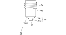
- FIG. 6 is a cross-sectional view showing the general configuration of container 70
- FIG. 7 is an external view showing the general configuration of container 70.
- Container 70 is a member that holds the injection liquid and defines a flow path for injecting the injection liquid pressurized by plunger 80 into a target area.
- Container 70 is made of a material that takes into consideration the pressurization by the plunger and the determination of the flow path.
- container 70 is made of a resin material. Note that container 70 is not limited to a resin material and can be made of the same type of material as attachment 30, for example.
- the container 70 has a storage space 75 that is a space capable of containing the injection liquid and is formed so that the stopper portion 82 of the plunger 80 can be advanced, and has a flow path 76 that connects the storage space 75 to an injection port (injection portion) 77 facing the outside of the container 70.
- the container 70 has a body portion 70a having a cylindrical shape that defines the storage space 75, and a nozzle portion 70c that is connected to the tip side of the body portion 70a and defines the flow path 76.
- the nozzle portion 70c has a tip portion 70c2 that includes a part of the flow path 76 on the injection port 77 side, and is configured to have a tapered portion 70c1 that connects the tip portion 70c2 and the body portion 70a and includes a tip side outer surface 70c3 that is inclined with respect to the central axis of the attachment 30 in the longitudinal direction.
- a position shift prevention device 50 described later is fitted onto the outer periphery of the tip portion 70c2.
- the tip side of the plunger 80 is fitted into the accommodation space 75 of the container 70 so that the stopper portion 82 of the plunger 80 can slide within the accommodation space 75 toward the nozzle portion 70c (toward the tip side).
- the space formed between the stopper portion 82 of the plunger 80 and the container 70 becomes a storage space for the injection liquid, i.e., a space in which the injection liquid is sealed.
- the tip surface of the stopper portion 82 and the inner wall surface of the container 70 located on the tip side of the tip surface of the stopper portion 82 define the storage space.
- the flow path of the container 70 opens into the tip surface 73 of the nozzle portion 70c, and an injection port 77 is formed. Therefore, when the plunger 80 slides inside the storage space 75, the ejection liquid contained in the storage space 75 is pressurized, and the ejection liquid passes through the flow path 76 and is ejected from the ejection port 77.
- the inner diameter of the flow path 76 provided in the container 70 is smaller than the inner diameter of the storage space 75. With this configuration, the highly pressurized injection liquid is injected to the outside from the injection port 77.
- a male threaded portion 74 is formed on the outer periphery of the base end side of the container 70 for attaching the container 70 to the attachment 30. The male threaded portion 74 screws into the female threaded portion 36 of the attachment 30.
- the tip shape of the stopper portion 82 of the plunger 80 is formed so as to generally match the tip shape of the storage space 75 defined by the inner wall surface 75a near the portion where the storage space 75 and the flow path 76 are connected (the innermost part of the storage space 75).
- the tip shape of the stopper portion 82 and the tip shape of the storage space 75 are both tapered shapes that decrease in diameter toward the tip side.
- the amount of pulling back of the plunger 80 at this time is set to an amount that allows the plunger 80 (plunger rod 81) protruding from the container 70 to reach the area in the internal space of the attachment 30 where the piston 40 is disposed when the container 70 is attached to the attachment 30 in this state.
- the actuator 20 When the container 70 with the storage space 75 filled with the injection liquid is attached to the attachment 30, the actuator 20 is inserted into the attachment 30 from the base end side. The actuator 20 is inserted until the tip surface of the piston 40 located at the tip portion 21b of the actuator 20 reaches the base end surface of the plunger 80 inside the attachment 30. At this time, the male thread portion 26 provided at the center portion 21a of the actuator 20 screws into the female thread portion 32 of the attachment 30, so that the actuator 20 and the attachment 30 are suitably connected. At this time, the piston 40 incorporated in the actuator 20 is connected to the plunger 80. Note that the connection between the piston 40 and the plunger 80 is not limited to a simple butt joint, and a fitting portion may be provided at the tip of the piston 40 and the base end of the plunger 80 to fit them together.
- the plunger 80 When the actuator 20 is attached to the attachment 30 to which the container 70 and plunger 80 are attached as described above, the plunger 80 is pushed from the piston 40 toward the tip side, and the plunger 80 is positioned at a predetermined position (pre-operation position) within the container 70. At this time, in response to the pushing of the plunger 80, excess injection liquid within the container 70 is discharged from the injection port 77, and a predetermined amount of injection liquid is left in the container 70.
- the volume of the space for containing the injection liquid formed between the plunger 80 positioned at the pre-operation position and the container 70 is determined to a volume that ensures an appropriate injection amount of the injection liquid when the syringe 1 is operated. Therefore, when the syringe assembly 10 is assembled as described above, the amount of injection liquid contained in the accommodation space 75 of the container 70, i.e., the amount of injection liquid to be injected, is set to a predetermined amount.
- the syringe assembly 10 configured in this manner is loaded into the housing 2 with the ignition pin 22b of the igniter 22 fitted into the socket 7 on the housing 2 side. This prepares the syringe 1 for use (see Figures 1 to 3).
- the user holds the housing 2 of such a syringe 1 in one hand and keeps sliding the first switch 5 located at the rear of the housing 2 for a predetermined period of time to put the syringe 1 into standby mode.
- the user presses the second switch 6 with the ejection port 77 in contact with the target area, activating the igniter 22, pressurizing the ejection liquid via the piston 40 and plunger 80, executing the ejection, and injecting the ejection liquid into the target area.
- a displacement prevention device 50 provided at the tip of the syringe 1.
- Fig. 8 is a diagram showing a schematic configuration of the displacement prevention device 50, and is a diagram (side view) of the displacement prevention device 50 viewed from a direction perpendicular to the injection direction of the syringe 1.
- Fig. 9 is a cross-sectional view of Fig. 8
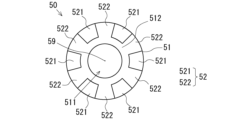
- Fig. 10 is a diagram of the displacement prevention device 50 viewed from the tip side
- Fig. 11 is a diagram of the displacement prevention device 50 viewed from the base end side
- Fig. 12 is a perspective view showing a schematic configuration of the displacement prevention device 50.
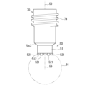
- the misalignment prevention device 50 includes a base 51 that is arranged around an axis 59 that is aligned with the ejection direction of the ejection liquid so as to surround the ejection port 77, and an uneven portion 52 that is provided on the target area side of the base 51.
- the base 51 is an annular member, and the tip 70c2 of the nozzle portion 70c is passed through the inner space 511 and fitted onto the tip 70c2. That is, the displacement prevention device 50 of this embodiment is attached to the container 70 of the syringe 1.
- the base 51 of this embodiment is circular, but is not limited to this, and may be a shape with a part of a circle missing, such as a C-shape.
- the displacement prevention device 50 may be connected by other connecting mechanisms such as screws and snap fits, not limited to fitting.
- the displacement prevention device 50 of this embodiment is attached detachably, but is not limited to this, and may be fixedly attached to the container 70 by adhesion, welding, etc.
- the attachment of the displacement prevention device 50 is not limited to joining the displacement prevention device 50 and the container 70 formed separately, but may be formed integrally with the displacement prevention device 50 and the container 70.
- the base end surface 513 of the base body 51 is tapered to fit the tip end outer surface 70c3 of the tapered portion 70c1 of the nozzle portion 70c.
- the uneven portion 52 has multiple protrusions 521 erected on a surface (base surface) 512 facing the target area of the substrate 51.
- the multiple protrusions 521 are spaced apart from one another in the circumferential direction of the base surface 512.
- recesses 522 are formed between each of the protrusions 521.
- the spacing between the protrusions 521 is uniform, and each protrusion 521 is arranged rotationally symmetrically around the axis 59.
- the reference numeral 90 indicates the area in which the eyeball to be injected is located when the syringe 1 is in use.
- the contact surface 523 on the tip side of the convex portion 521 contacts the eyeball.
- the contact surface 523 of each convex portion 521 is formed to conform to a predetermined curved surface corresponding to the eyeball.
- the predetermined curved surface is, for example, a spherical surface.
- the contact surface 523 is formed along a spherical surface with an average diameter of the eyeball, so that the displacement prevention device 50 can be used for general purposes.
- the contact surface 523 may also be formed along a spherical surface slightly larger than the average diameter of the eyeball, so that when the displacement prevention device 50 is pressed against the eyeball, the inner side of the contact surface 523 mainly contacts the eyeball when the eyeball has a diameter smaller than the average, and the outer side of the contact surface 523 mainly contacts the eyeball when the eyeball has a diameter larger than the average.
- the predetermined curved surface along which the contact surface 523 follows is not limited to a spherical surface, and may be a curved surface that deviates from a spherical surface as long as the contact surface 523 of each convex portion 521 contacts the eyeball.
- the contact surface 523 may be formed along an aspheric surface with a high curvature on the axis 59 side (inner side) and a low curvature on the side away from the axis 59 (outer side) in the radial direction of the displacement prevention device 50.
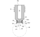
- FIG. 13 is a schematic diagram showing the positional relationship between the contact surface 523 of the displacement prevention device 50 and the ejection port 77.
- the contact surface 523 and the ejection port 77 of the displacement prevention device 50 are arranged along a predetermined curved surface 91. Therefore, when the ejection port 77 of the syringe 1 is pressed against the eyeball, the contact surface 523 of each convex portion 521 comes into contact with the eyeball.
- the contact surface 523 and the ejection port 77 are not limited to being arranged strictly on the predetermined curved surface 91.
- the ejection port 77 may be arranged at a position a predetermined distance away from the predetermined curved surface 91 toward the base end, taking into account the distance (predetermined distance) at which the convex portion 521 bites into the eyeball surface. This allows the ejection port 77 to be configured to come into contact with the eyeball surface with each convex portion 521 biting into the eyeball when the ejection port 77 of the syringe 1 is pressed against the eyeball.
- the uneven portion 52 of the misalignment prevention device 50 comes into contact with the surface of the eyeball, increasing the frictional force compared to when the injection nozzle 77 is simply pressed against the eyeball, thereby preventing the syringe 1 from shifting relative to the target area of the eyeball.
- the projection 521 of the misalignment prevention device 50 comes into contact with the eyeball at a position radially away from the injection port 77, so contact between the eyeball surface and the syringe tip is stable, preventing misalignment.
- the projections 521 of the uneven portion 52 of the misalignment prevention device 50 are arranged in rotational symmetry, so that the force exerted when the syringe 1 is pressed against the eyeball is evenly applied around the injection port 77, effectively preventing the syringe 1 from misaligning.
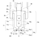
- Second Embodiment This embodiment is different from the first embodiment described above in that it includes a container holder 71 that holds a container 70, and a displacement prevention device 50A is attached to the container holder (holding portion) 71. Since the other configurations are the same as those of the first embodiment described above, the same elements are denoted by the same reference numerals, and repeated explanations will be omitted.
- FIG. 14 is a diagram showing the schematic configuration of the displacement prevention device 50A and container 70A according to the second embodiment.
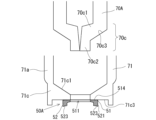
- FIG. 15 is a diagram for explaining the positional relationship between the container 70A and the container holder 71 according to the second embodiment.
- the container 70A of this embodiment does not have a male threaded portion that screws into the female threaded portion 36 formed on the inner wall of the tip side of the attachment 30. Therefore, the container 70A is attached to the attachment 30 by a container holder 71.
- the container holder 71 has a body 71a that defines a space that contains the container 70A, a screw-in portion 71b that is connected to the base end side of the body 71a and has a male thread that screws into the female threaded portion 36, and a contact portion 71c that is connected to the tip side of the body 71a and has an inner surface 71c1 (see Figure 15) that comes into surface contact with the tip side outer surface 70c3 of the container 70A.
- the contact portion 71c is provided with an opening 71c2 through which the tip end 70c2 of the container 70A can pass.
- the displacement prevention device 50A is provided on the tip surface 71c3 of the container holder 71.
- the displacement prevention device 50A includes a base 51 arranged around an axis 59 along the injection direction of the injection liquid so as to surround the periphery of the opening 71c2, and an uneven portion 52 provided on the target area side of the base 51.
- the base end side surface (base end surface) 514 of the base 51 is attached to the tip surface 71c3 of the container holder 71 by adhesion, welding, or the like.
- the displacement prevention device 50 of this embodiment is fixedly attached to the container holder 71, but it may be detachably attached via a screw or a joint.
- the attachment of the displacement prevention device 50 is not limited to joining the displacement prevention device 50 and the container holder 71 formed separately, but may be formed integrally with the displacement prevention device 50 and the container holder 71.
- the container 70A is accommodated in the container holder 71 having such a configuration so that the tip 70c2 passes through the opening 71c2. At this time, the container 70A is in a state where the injection target substance is filled in the accommodation space 75 and the plunger 80 is also loaded. In this accommodated state, the tip side outer surface 70c3 of the container 70A and the inner surface 71c1 of the container holder 71 are in surface contact, and the base end side is in contact with the threaded portion 71b of the container holder 71.
- the male thread formed in the threaded portion 71b of the container holder 71 and the female threaded portion 36 of the attachment 30 are screwed together until the end face on the base end side of the base end 70b of the container 70A comes into contact with the end face 35a of the third region 35 of the attachment 30.
- the container 70A is attached to the attachment 30 in a state in which the fastening force of the screwing presses the tip side outer surface 70c3 of the container 70A from the tip side toward the base end side by the container holder 71, i.e., in the opposite direction to the movement direction of the plunger 80.
- the plunger 80 is positioned across the storage space 75 in the container 70A and the area in the attachment 30 where the plunger 80 is generally positioned.
- the process of assembling the syringe assembly 10, such as by attaching the actuator 20 to the attachment 30 in this state, and the process of assembling the syringe 1 are the same as those in the first embodiment described above.
- the syringe 1 of this embodiment is equipped with a misalignment prevention device 50A at the tip of the container holder 71, and when the injection port 77 is pressed against the eyeball during use of the syringe 1, the uneven portion 52 of the misalignment prevention device 50A comes into contact with the surface of the eyeball, thereby preventing the syringe 1 from shifting.
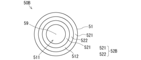
- FIG. 16 is a cross-sectional view showing the schematic configuration of a displacement prevention device 50B and a container 70 according to the third embodiment
- FIG. 17 is a view of the displacement prevention device 50B seen from the tip side.
- the displacement prevention device 50B of this embodiment comprises a base 51 surrounding the periphery of the injection port 77 and an uneven portion 52B provided on the target area side of the base 51.
- the uneven portion 52B is formed by erecting multiple convex portions 521B in a concentric pattern on the surface (base surface) 512 of the base 51 facing the target area.
- the convex portions 521B are spaced apart from each other in the radial direction of the base surface 512. This forms concave portions 522B between the convex portions 521B.
- the convex portions 521B are spaced apart evenly, and the convex portions 521B are arranged rotationally symmetrically around the axis 59.
- each convex portion 521B is formed in a circular shape when viewed from the tip side, it may be divided into multiple parts so that part of the circle is missing.
- the uneven portion 52B of the misalignment prevention device 50B comes into contact with the surface of the eyeball, increasing the frictional force compared to when the injection nozzle 77 is simply pressed against the eyeball, thereby preventing the syringe 1 from misaligning with the target area of the eyeball.
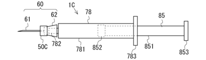
- syringe 1C is a needled syringe instead of a needleless syringe, and a displacement prevention device 50C is attached to the needle hub. Since the other configurations are the same as those of the first embodiment, the same elements are denoted by the same reference numerals, and a repeated description will be omitted.
- FIG. 18 is a schematic diagram of a syringe 1C according to the fourth embodiment
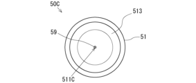
- FIG. 19 is a diagram showing the tip side of a displacement prevention device 50C according to the fourth embodiment
- FIG. 20 is a diagram showing the base end side of a displacement prevention device 50C according to the fourth embodiment.
- the syringe 1C has a syringe barrel 78, an injection rod 85, and an injection needle 60.
- the syringe 78 has a generally cylindrical outer barrel body 781 with a tip portion 782 at its tip.
- the tip portion 782 is smaller in diameter than the outer barrel body 781 and is generally cylindrical.
- the outer barrel body 781 and tip portion 782 are connected so that their internal spaces are connected. In other words, the tip side of the internal space in the outer barrel body 781 is closed except for the portion that is connected to the internal space of the tip portion 782.
- the rear end of the outer barrel body 781 is provided with a flange (finger hook) 783 that protrudes radially from the outer circumferential surface of the cylinder.
- the syringe barrel 78 is made of, for example, transparent plastic.
- the material of the first outer barrel 11 is not particularly limited, but may be, in addition to plastic, for example, metal, glass, or ceramic.
- the injection rod 85 has a rod-shaped rod portion 851, a gasket 852 provided at the tip of the rod portion 851, and a flange 853 provided at the rear end of the rod portion 851.
- the tip side of the injection rod 85 is inserted into the internal space from the rear end of the outer cylinder body 781.
- the gasket 852 of the injection rod 85 inserted into the internal space of the outer cylinder body 781 contacts the inner circumferential surface of the outer cylinder body 781 and can move (advance and retreat) along the inner circumferential surface to the tip side or rear end side in this state.
- the injection rod 85 is held so as to be able to move forward and backward with the gasket 852 at the tip contacting the inner circumferential surface of the outer cylinder body 781 and keeping the internal space airtight.
- the injection needle 60 comprises a needle tube (ejection portion) 61 and a needle hub 62, and the needle tube 61 and the needle hub 62 are connected so that their internal spaces are in communication.
- a recess is provided on the base end side of the needle hub 62 for fitting with the barrel tip 782 of the syringe barrel 78.
- syringe 1C which is an assembly of syringe barrel 78, injection rod 85, and injection needle 60
- the tip of injection needle 60 is immersed in the injection liquid corresponding to the injection target substance and the injection rod 85 is moved toward the base end relative to the syringe barrel 78
- the injection liquid is sucked in and stored in the syringe barrel 78.
- the tip of injection needle 60 of syringe 1C is inserted into the target area with the injection liquid stored in the syringe barrel 78 and the injection rod 85 is moved toward the tip end relative to the syringe barrel 78, the injection liquid is pushed out and injected into the target area.
- the displacement prevention device 50C of this embodiment includes a base 51 that is arranged around an axis 59 that is aligned with the injection direction of the injection liquid so as to surround the injection needle 60, and an uneven portion 52 that is provided on the target area side of the base 51.
- the base 51 is an annular member, and the needle tube 61 of the injection needle 60 is passed through the inner space 511C and fitted onto the tip side of the needle hub 62.
- the displacement prevention device 50C in this embodiment is detachably attached by fitting the base 51 and the needle hub 62 together, but this is not limited to this, and the device may be fixed to the needle hub 62 by adhesion, welding, or the like.
- the displacement prevention device 50C may also be molded integrally with the needle hub 62.
- the base end surface 513 of the base body 51 is tapered to fit the outer surface (tapered surface) of the tip end of the needle base 62.
- the uneven portion 52 has multiple protrusions 521 erected on a surface (base surface) 512 of the base 51 that faces the target area.
- the structure and function of the uneven portion 52 are the same as those in the above-described embodiment.
- the tip side of the injection needle 60 is inserted into the target area until the misalignment prevention device 50C abuts the symmetric area, and in this state the injection rod 85 is moved toward the tip side relative to the syringe barrel 78, thereby injecting the injection liquid into the target area.
- the uneven portion 52 of the misalignment prevention device 50C comes into contact with the surface of the symmetric area (e.g., the surface of the eyeball), thereby preventing the syringe 1C from shifting relative to the target area.
- This embodiment is different from the fourth embodiment in that the injection needle 60D includes a sleeve 63 and a shield 64, and the displacement prevention device 50D is attached to the sleeve 63. Since the other configurations are the same as those of the fourth embodiment, the same elements are denoted by the same reference numerals, and the repeated description will be omitted.
- FIG. 21 is a schematic diagram of a syringe 1D according to the fifth embodiment
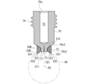
- FIG. 22 is a diagram showing a cross section of the tip side of the syringe 1D.
- the injection needle 60D is equipped with a needle tube 61, a needle base 62, a sleeve 63, a shield 64, and a spring 65.
- the sleeve 63 is a generally cylindrical member that houses the needle hub 62 and the base end side of the needle tube 61.
- the sleeve 63 houses at least the base end side of the shield 64 and holds the shield 64 so that it can move forward and backward along the injection direction of the syringe 1D.
- the shield 64 is a generally cylindrical member that is arranged to surround the needle tube 61 in the radial direction.
- the tip side of the shield 64 is provided with a hole 641 through which the needle tube 61 passes.
- the base side of the shield 64 is provided with a spring 65 that biases the shield 64 toward the tip side. Therefore, when the shield 64 is not receiving an external force (when not in use), the shield 64 covers the tip portion of the needle tube 61.
- the shield 64 compresses the spring 65 and moves toward the base end side, exposing the tip portion of the needle tube 61.
- the sleeve 63 is connected to the needle hub 62, and the needle hub 62 is fitted onto the tip 782 of the syringe barrel 78, thereby attaching the injection needle 60D including the sleeve 63 to the syringe barrel 78.
- the injection needle 60D may be attached to the syringe barrel 78 while the syringe barrel 78 is already filled with the injection liquid, or the injection needle 60D may be attached to the syringe barrel 78 and then the injection liquid may be filled into the syringe barrel 78 via the injection needle 60D.
- the displacement prevention device 50D of this embodiment includes a base 51 that is arranged around an axis 59 that is aligned with the injection direction of the injection liquid so as to surround the needle tube 61 and the shield 64, and an uneven portion 52 that is provided on the target area side of the base 51.
- the base 51 is an annular member, and the needle tube 61 and shield 64 of the injection needle 60D are passed through the inner space 511D, and the base 51 is fitted to the tip side of the sleeve 63.
- the displacement prevention device 50D in this embodiment is detachably attached by fitting the base 51 to the sleeve 63, but this is not limited to this, and the device may be fixed to the sleeve 63 by adhesion, welding, etc.
- the displacement prevention device 50D may be molded integrally with the sleeve 63.
- the uneven portion 52 has multiple protrusions 521 erected on a surface (base surface) 512 of the substrate 51 that faces the target area.
- the structure and function of the uneven portion 52 are the same as those in the above-described embodiment.
- the tip of the syringe 1D When used, the tip of the syringe 1D is pressed against the target area. At this time, the shield 64 is located at the tip and covers the needle tube 61 until the syringe 1D touches the target area. When the shield 64 reaches the target area, it hits the surface of the target area and stops moving, but the part of the syringe 1D other than the shield 64 is advanced relative to the shield 64 while compressing the spring 65. The needle tube 61 of the syringe 1D is then inserted into the target area until the displacement prevention device 50D abuts against the target area, and in this state the injection rod 85 is moved toward the tip side relative to the syringe barrel 78 to inject the injection liquid into the target area.
- the uneven portion 52 of the displacement prevention device 50D comes into contact with the surface of the target area (e.g., the surface of the eyeball), thereby suppressing the displacement of the syringe 1C relative to the target area.
- Syringe 2 Housing 3: Power cable 4: Connector 7: Socket 10: Syringe assembly 20: Actuator 20a: Combustion chamber 21: Body 22: Igniter 26: Male threaded portion 27: Opening 30: Attachment 31: Body 32: Female threaded portion 35: Third region 36: Female threaded portion 40: Piston 50: Positional deviation prevention device 50A: Positional deviation prevention device 51: Base 52: Uneven portion 59: Shaft 70: Container 70A: Container 70c: Nozzle portion 70c1: Tapered portion 70c2: Tip portion 70c3: Tip side outer surface 71: Container holder 73: Tip surface 74: Male threaded portion 75: Storage space 75a: Inner wall surface 76: Flow path 77: Injection port 80: Plunger 81: Plunger rod 82 : Stopper portion 91 : Predetermined curved surface 511 : Inner space 512 : Base surface 521 : Convex portion 522 : Concave portion 523 : Contact surface
Landscapes
- Health & Medical Sciences (AREA)
- Animal Behavior & Ethology (AREA)
- Veterinary Medicine (AREA)
- Vascular Medicine (AREA)
- Biomedical Technology (AREA)
- Heart & Thoracic Surgery (AREA)
- Public Health (AREA)
- Engineering & Computer Science (AREA)
- General Health & Medical Sciences (AREA)
- Life Sciences & Earth Sciences (AREA)
- Hematology (AREA)
- Anesthesiology (AREA)
- Ophthalmology & Optometry (AREA)
- Nuclear Medicine, Radiotherapy & Molecular Imaging (AREA)
- Surgery (AREA)
- Infusion, Injection, And Reservoir Apparatuses (AREA)
Abstract
Description
注射対象とする眼球の対象領域に対して注射目的物質を射出部から射出する注射器と前記対象領域とのずれを抑制するための位置ずれ防止具であって、
前記射出部の周囲を囲むように、前記注射目的物質の射出方向に沿った軸の軸回りに配置される基体と、
前記基体の前記対象領域側に設けられた凹凸部と
を備える。
前記注射器が、前記射出部である射出口から前記注射目的物質を射出することにより注射針を介することなく前記注射目的物質を前記対象領域に対して注入する注射器であってもよい。
前記無針注射器が、前記注射目的物質が収容される収容空間を有するとともに該注射目的物質が前記対象領域に対して射出される前記射出口を有する収容部を備え、
前記基体が、前記無針注射器の前記収容部に取り付けられてもよい。
前記無針注射器は、前記注射目的物質が収容される収容空間を有するとともに該注射目的物質が前記対象領域に対して射出される前記射出口を有する収容部と、前記収容部を保持する保持部とを備え、
前記基体が、前記無針注射器の前記保持部に取り付けられてもよい。
前記注射器の前記射出部が注射針を備え、
前記基体が、前記注射針を軸回りに囲む位置に配置されてもよい。
前記凹凸部は、前記軸回りに複数の突起を備え、各突起の前記眼球と当接する当接面が、前記眼球に対応する所定曲面に沿って形成されてもよい。
注射対象とする眼球の対象領域に対して注射目的物質を射出部から射出する注射器であって、
前記注射目的物質が収容される収容空間を有するとともに該注射目的物質が前記対象領域に対して射出される前記射出部を有する収容部と、
前記対象領域に対する前記無針注射器のずれを抑制するための位置ずれ防止具と、を備え、
前記位置ずれ防止具が、
前記射出部の周囲を囲むように、前記注射目的物質の射出方向に沿った軸の軸回りに配置される基体と、
前記基体の前記対象領域と対向する面に設けられた凹凸部と
を備える。
前記収容部を保持する保持部を更に備え、
前記基体が、前記無針注射器の前記保持部に取り付けられてもよい。
前記射出部が注射針を備え、
前記基体が、前記注射針を軸回りに囲む位置に配置されてもよい。
以下に、図面を参照して本願開示の実施形態に係る無針注射器(以下、単に「注射器」と称する)1について説明する。当該注射器1は、火薬の燃焼エネルギーを利用して、本願の注射目的物質に相当する射出液を対象領域に射出する無針注射器、すなわち、注射針を介することなく、射出液を対象領域に射出して注射を行う装置である。
ここで、図1は、注射器1の外観を概略的に示す図である。図2は、注射器1の第1の断面図であり、その断面は、後述の図4におけるAA断面である。また、図3は、注射器1の第2の断面図であり、その断面は、後述の図4におけるBB断面であり、BB断面はAA断面に直交する。図4は、注射器1を構成するハウジング2の構成を示す図、図5は、注射器アセンブリ10の概略構成を示す図である。注射器1は、ハウジング2に注射器アセンブリ10が取り付けられて形成される。また、ハウジング2には、注射器アセンブリ10内の点火器22に駆動電流を供給するための電源ケーブル3(図1)が接続される。
注射器1の組立において、先ず、注射器アセンブリ10の組立について説明する。コンテナ70の収容空間75にプランジャ80のストッパ部82を最奥部まで挿入した状態で、コンテナ70の射出口77を射出液と連通させてプランジャ80を引き戻す。ストッパ部82と収容空間75の内壁面75aは密に接触しているため、その引き戻し動作によって収容空間内に負圧を発生させ、射出口77から収容空間75内に射出液を充填することができる。このときのプランジャ80の引き戻し量は、その状態でコンテナ70をアタッチメント30に取り付けたときに、コンテナ70から飛び出しているプランジャ80(プランジャロッド81)が、アタッチメント30の内部空間において、ピストン40が配置される領域に到達する程度の引き戻し量とされる。
次に、注射器1の先端に設けられる位置ずれ防止具50について説明する。図8は、位置ずれ防止具50の概略構成を示す図であり、注射器1の射出方向と直交する方向から位置ずれ防止具50を見た図(側面図)である。図9は、図8の断面図、図10は、位置ずれ防止具50を先端側から見た図、図11は、位置ずれ防止具50を基端側から見た図、図12は、位置ずれ防止具50の概略構成を示す斜視図である。
本実施形態は、前述の第一実施形態と比べて、コンテナ70を保持するコンテナホルダ71を備え、コンテナホルダ(保持部)71に位置ずれ防止具50Aを取り付けた構成が異なっている。なお、その他の構成は、前述の第一実施形態と同じであるため、同一の要素に同符号を付すなどして、再度の説明を省略する。
本実施形態は、前述の第一実施形態と比べて、凹凸部52Bの構成が異なっている。なお、その他の構成は、前述の第一実施形態と同じであるため、同一の要素に同符号を付すなどして、再度の説明を省略する。
本実施形態は、前述の第一実施形態と比べ、注射器1Cが、無針注射器ではなく、有針の注射器であって、この針基に位置ずれ防止具50Cを取り付けた構成が異なっている。なお、その他の構成は、前述の第一実施形態と同じであるため、同一の要素に同符号を付すなどして、再度の説明を省略する。
本実施形態は、前述の第四実施形態と比べ、注射針60Dがスリーブ63とシールド64を備え、位置ずれ防止具50Dがスリーブ63に取り付けられた構成が異なっている。なお、その他の構成は、前述の第四実施形態と同じであるため、同一の要素に同符号を付すなどして、再度の説明を省略する。
2 :ハウジング
3 :電源ケーブル
4 :コネクタ
7 :ソケット
10 :注射器アセンブリ
20 :アクチュエータ
20a :燃焼室
21 :ボディ
22 :点火器
26 :雄ネジ部
27 :開口部
30 :アタッチメント
31 :ボディ
32 :雌ネジ部
35 :第3領域
36 :雌ネジ部
40 :ピストン
50 :位置ずれ防止具
50A :位置ずれ防止具
51 :基体
52 :凹凸部
59 :軸
70 :コンテナ
70A :コンテナ
70c :ノズル部
70c1 :テーパ部
70c2 :先端部
70c3 :先端側外表面
71 :コンテナホルダ
73 :先端面
74 :雄ネジ部
75 :収容空間
75a :内壁面
76 :流路
77 :射出口
80 :プランジャ
81 :プランジャロッド
82 :ストッパ部
91 :所定曲面
511 :内側空間
512 :ベース面
521 :凸部
522 :凹部
523 :当接面
Claims (12)
- 注射対象とする眼球の対象領域に対して注射目的物質を射出部から射出する注射器と前記対象領域とのずれを抑制するための位置ずれ防止具であって、
前記射出部の周囲を囲むように、前記注射目的物質の射出方向に沿った軸の軸回りに配置される基体と、
前記基体の前記対象領域側に設けられた凹凸部と
を備えた位置ずれ防止具。 - 前記注射器が、前記射出部である射出口から前記注射目的物質を射出することにより注射針を介することなく前記注射目的物質を前記対象領域に対して注入する無針注射器である請求項1に記載の位置ずれ防止具。
- 前記無針注射器は、前記注射目的物質が収容される収容空間を有するとともに該注射目的物質が前記対象領域に対して射出される前記射出口を有する収容部を備え、
前記基体が、前記無針注射器の前記収容部に取り付けられる、
請求項2に記載の位置ずれ防止具。 - 前記無針注射器は、前記注射目的物質が収容される収容空間を有するとともに該注射目的物質が前記対象領域に対して射出される前記射出口を有する収容部と、前記収容部を保持する保持部とを備え、
前記基体が、前記無針注射器の前記保持部に取り付けられる、
請求項2に記載の位置ずれ防止具。 - 前記注射器の前記射出部が注射針を備え、
前記基体が、前記注射針を前記軸回りに囲む位置に配置される
請求項1に記載の位置ずれ防止具。 - 前記凹凸部は、前記軸回りに複数の突起を備え、各突起の前記眼球と当接する当接面が、前記眼球に対応する所定曲面に沿って形成されている、
請求項2~5の何れか1項に記載の位置ずれ防止具。 - 注射対象とする眼球の対象領域に対して注射目的物質を射出部から射出する注射器であって、
前記注射目的物質が収容される収容空間を有するとともに該注射目的物質が前記対象領域に対して射出される前記射出部を有する収容部と、
前記対象領域に対する前記注射器のずれを抑制するための位置ずれ防止具と、を備え、
前記位置ずれ防止具が、
前記射出部の周囲を囲むように、前記注射目的物質の射出方向に沿った軸の軸回りに配置される基体と、
前記基体の前記対象領域と対向する面に設けられた凹凸部と
を備えた、
注射器。 - 前記注射器が、前記射出部である射出口から前記注射目的物質を射出することにより注射針を介することなく前記注射目的物質を前記対象領域に対して注入する無針注射器である請求項7に記載の注射器。
- 前記基体が、前記無針注射器の前記収容部に取り付けられる請求項8に記載の注射器。
- 前記収容部を保持する保持部を更に備え、
前記基体が、前記無針注射器の前記保持部に取り付けられる、
請求項8に記載の注射器。 - 前記射出部が注射針を備え、
前記基体が、前記注射針を前記軸回りに囲む位置に配置される
請求項7に記載の注射器。 - 前記凹凸部は、前記軸回りに複数の突起を備え、各突起の前記眼球と当接する当接面が、前記眼球に対応する所定曲面に沿って形成されている、
請求項7~11の何れか1項に記載の注射器。
Priority Applications (2)
| Application Number | Priority Date | Filing Date | Title |
|---|---|---|---|
| JP2025531569A JPWO2025009547A1 (ja) | 2023-07-05 | 2024-07-03 | |
| CN202480042833.6A CN121419804A (zh) | 2023-07-05 | 2024-07-03 | 防错位件和无针注射器 |
Applications Claiming Priority (2)
| Application Number | Priority Date | Filing Date | Title |
|---|---|---|---|
| JP2023110824 | 2023-07-05 | ||
| JP2023-110824 | 2023-07-05 |
Publications (1)
| Publication Number | Publication Date |
|---|---|
| WO2025009547A1 true WO2025009547A1 (ja) | 2025-01-09 |
Family
ID=94171570
Family Applications (1)
| Application Number | Title | Priority Date | Filing Date |
|---|---|---|---|
| PCT/JP2024/024043 Ceased WO2025009547A1 (ja) | 2023-07-05 | 2024-07-03 | 位置ずれ防止具及び無針注射器 |
Country Status (3)
| Country | Link |
|---|---|
| JP (1) | JPWO2025009547A1 (ja) |
| CN (1) | CN121419804A (ja) |
| WO (1) | WO2025009547A1 (ja) |
Citations (5)
| Publication number | Priority date | Publication date | Assignee | Title |
|---|---|---|---|---|
| US3138157A (en) * | 1961-05-12 | 1964-06-23 | Z & W Mfg Corp | Inoculant injector instrument |
| US3788315A (en) * | 1971-04-20 | 1974-01-29 | S Laurens | Disposable cutaneous transjector |
| JPH03207374A (ja) * | 1989-11-09 | 1991-09-10 | Bioject Inc | 無針皮下注射器 |
| JP2005516737A (ja) * | 2002-02-11 | 2005-06-09 | アンタレス・ファーマ・インコーポレーテッド | 皮内注射器 |
| JP2007044529A (ja) | 2005-08-10 | 2007-02-22 | Alza Corp | 針を用いないジェット式注射薬物送達装置 |
-
2024
- 2024-07-03 JP JP2025531569A patent/JPWO2025009547A1/ja active Pending
- 2024-07-03 CN CN202480042833.6A patent/CN121419804A/zh active Pending
- 2024-07-03 WO PCT/JP2024/024043 patent/WO2025009547A1/ja not_active Ceased
Patent Citations (6)
| Publication number | Priority date | Publication date | Assignee | Title |
|---|---|---|---|---|
| US3138157A (en) * | 1961-05-12 | 1964-06-23 | Z & W Mfg Corp | Inoculant injector instrument |
| US3788315A (en) * | 1971-04-20 | 1974-01-29 | S Laurens | Disposable cutaneous transjector |
| JPH03207374A (ja) * | 1989-11-09 | 1991-09-10 | Bioject Inc | 無針皮下注射器 |
| JP2005516737A (ja) * | 2002-02-11 | 2005-06-09 | アンタレス・ファーマ・インコーポレーテッド | 皮内注射器 |
| JP2007044529A (ja) | 2005-08-10 | 2007-02-22 | Alza Corp | 針を用いないジェット式注射薬物送達装置 |
| JP2007044531A (ja) * | 2005-08-10 | 2007-02-22 | Alza Corp | 針を用いないジェット注入薬物送達装置を作製するための方法 |
Also Published As
| Publication number | Publication date |
|---|---|
| CN121419804A (zh) | 2026-01-27 |
| JPWO2025009547A1 (ja) | 2025-01-09 |
Similar Documents
| Publication | Publication Date | Title |
|---|---|---|
| JP7516261B2 (ja) | 無針注射器 | |
| JP7119121B2 (ja) | 無針注射器 | |
| US20260108677A1 (en) | Needleless injector | |
| WO2025009547A1 (ja) | 位置ずれ防止具及び無針注射器 | |
| JP7429650B2 (ja) | 無針注射器 | |
| JP7148627B2 (ja) | アダプタ、及び射出液の移送方法 | |
| WO2025018415A1 (ja) | 硝子体内投与用具及び無針注射器 | |
| JP6345978B2 (ja) | 無針注射器 | |
| JP7516223B2 (ja) | 無針注射器 | |
| CN116437974A (zh) | 无针注射器用装置组装体 | |
| JP7576089B2 (ja) | 無針注射器 | |
| JP7168489B2 (ja) | 投与装置、及び投与装置の製造方法 | |
| WO2025104987A1 (ja) | 注射器用のコンテナユニット、及び注射器 |
Legal Events
| Date | Code | Title | Description |
|---|---|---|---|
| 121 | Ep: the epo has been informed by wipo that ep was designated in this application |
Ref document number: 24836060 Country of ref document: EP Kind code of ref document: A1 |
|
| ENP | Entry into the national phase |
Ref document number: 2025531569 Country of ref document: JP Kind code of ref document: A |
|
| WWE | Wipo information: entry into national phase |
Ref document number: 2025531569 Country of ref document: JP |
|
| WWE | Wipo information: entry into national phase |
Ref document number: 202617001306 Country of ref document: IN |
|
| WWP | Wipo information: published in national office |
Ref document number: 202617001306 Country of ref document: IN |
|
| WWE | Wipo information: entry into national phase |
Ref document number: 2024836060 Country of ref document: EP |
|
| NENP | Non-entry into the national phase |
Ref country code: DE |
|
| ENP | Entry into the national phase |
Ref document number: 2024836060 Country of ref document: EP Effective date: 20260205 |