WO2025009529A1 - プロセスデータの編集方法、プロセスの異常検知方法、プロセスデータの編集装置およびプロセスの異常検知装置 - Google Patents
プロセスデータの編集方法、プロセスの異常検知方法、プロセスデータの編集装置およびプロセスの異常検知装置 Download PDFInfo
- Publication number
- WO2025009529A1 WO2025009529A1 PCT/JP2024/023935 JP2024023935W WO2025009529A1 WO 2025009529 A1 WO2025009529 A1 WO 2025009529A1 JP 2024023935 W JP2024023935 W JP 2024023935W WO 2025009529 A1 WO2025009529 A1 WO 2025009529A1
- Authority
- WO
- WIPO (PCT)
- Prior art keywords
- equipment
- raw materials
- process data
- editing
- time delay
- Prior art date
- Legal status (The legal status is an assumption and is not a legal conclusion. Google has not performed a legal analysis and makes no representation as to the accuracy of the status listed.)
- Ceased
Links
Images


Classifications
-
- C—CHEMISTRY; METALLURGY
- C22—METALLURGY; FERROUS OR NON-FERROUS ALLOYS; TREATMENT OF ALLOYS OR NON-FERROUS METALS
- C22B—PRODUCTION AND REFINING OF METALS; PRETREATMENT OF RAW MATERIALS
- C22B1/00—Preliminary treatment of ores or scrap
- C22B1/14—Agglomerating; Briquetting; Binding; Granulating
- C22B1/16—Sintering; Agglomerating
- C22B1/20—Sintering; Agglomerating in sintering machines with movable grates
-
- G—PHYSICS
- G05—CONTROLLING; REGULATING
- G05B—CONTROL OR REGULATING SYSTEMS IN GENERAL; FUNCTIONAL ELEMENTS OF SUCH SYSTEMS; MONITORING OR TESTING ARRANGEMENTS FOR SUCH SYSTEMS OR ELEMENTS
- G05B19/00—Program-control systems
- G05B19/02—Program-control systems electric
- G05B19/418—Total factory control, i.e. centrally controlling a plurality of machines, e.g. direct or distributed numerical control [DNC], flexible manufacturing systems [FMS], integrated manufacturing systems [IMS] or computer integrated manufacturing [CIM]
Definitions
- the present invention relates to a method for editing process data, a method for detecting process anomalies, a device for editing process data, and a device for detecting process anomalies.
- the sintering process in the steel industry spans multiple manufacturing steps, such as granulation, firing, and cooling, and sintered ore is produced over a long period of time. Therefore, when analyzing the process data given to the raw materials for certain product or operational characteristics, it is necessary to correct for time delays that take into account the differences in the times at which each process data was given.
- a data set required for analysis may be created by adding a fixed time correction (time delay correction) according to the process data of interest.
- time delay correction a fixed time correction
- Patent Document 1 proposes a method of measuring the temperature distribution and changes in temperature on a sintering machine using thermometers attached to the raw materials and pallets. In this way, data obtained from a thermometer that moves with the raw materials laid on the pallet does not require consideration of the above-mentioned time delay correction.
- Patent Document 2 also proposes a method of acquiring data such as the temperature distribution at each position within the sintering machine by using RFID tags to individually identify the pallets of the sintering machine.
- the wireless master unit does not correspond to an individual pallet, so it is uncertain at what position on the sintering machine the obtained data, such as temperature distribution, was measured. For this reason, it can be said that the method proposed in Patent Document 1 is not suitable for analysis that focuses on the relationship between the obtained data, such as temperature distribution, and other process data.
- Patent Document 2 solves the problems of Patent Document 1, the equipment it targets is limited to sintering machines. Therefore, in the method proposed in Patent Document 2, in order to analyze the quality of raw materials and the characteristics of operation from the relationship between process data across processes, such as the granulation process and the firing process, and the temperature distribution on the sintering machine, it is still necessary to take into account the time delay correction described above.
- the present invention has been made in consideration of the above, and aims to provide a process data editing method, a process anomaly detection method, a process data editing device, and a process anomaly detection device that are capable of correlating various process data in a manufacturing line by correcting time delays.
- the process data editing method of the present invention includes a collection step in which a collection means provided in a computer collects process data indicating the operating status of a plurality of pieces of equipment in a production line, the plurality of pieces of equipment being made up of a plurality of devices that perform a predetermined process on raw materials and a transport device that connects the plurality of devices and transports the raw materials, and an editing step in which an editing means provided in the computer associates the process data by correcting a time delay according to the type of equipment through which the raw materials pass in the production line.
- the editing step corrects the time delay based on the conveying speed of the raw materials by the conveying device and the equipment length of the conveying device.
- the editing step corrects the time delay based on the weight of the deposited raw materials and the insertion speed of the raw materials at the inlet side of the equipment, or based on the weight of the deposited raw materials and the discharge speed of the raw materials at the outlet side of the equipment.
- the process anomaly detection method of the present invention includes a collection step in which a collection means provided in a computer collects process data indicating the operating status of the plurality of pieces of equipment in a production line consisting of a plurality of devices that perform a predetermined process on raw materials and a transport device that connects the plurality of devices and transports the raw materials, an editing step in which an editing means provided in the computer associates the process data by correcting a time delay according to the type of equipment through which the raw materials pass in the production line, and an anomaly detection step in which an anomaly detection means provided in the computer detects an anomaly in the quality or productivity of the raw materials in the production line based on the process data with the time delay corrected.
- the manufacturing line is a sintering process line in a steelworks.
- the process data editing device of the present invention includes a collection means for collecting process data indicating the operating status of a production line made up of multiple pieces of equipment, the multiple pieces of equipment being made up of multiple devices that perform a predetermined process on raw materials and a transport device that connects the multiple devices and transports the raw materials, and an editing means for correlating the process data by correcting time delays depending on the type of equipment through which the raw materials pass on the production line.
- the editing means corrects the time delay based on the conveying speed of the raw materials by the conveying device and the equipment length of the conveying device.
- the editing means corrects the time delay based on the weight of the stacked raw materials and the insertion speed of the raw materials at the inlet side of the equipment, or based on the weight of the stacked raw materials and the discharge speed of the raw materials at the outlet side of the equipment.
- the process anomaly detection device of the present invention comprises a collection means for collecting process data indicating the operating status of a production line made up of a plurality of pieces of equipment, the plurality of pieces of equipment being made up of a plurality of devices that perform a predetermined process on raw materials and a transport device that connects the plurality of devices and transports the raw materials, an editing means for correlating the process data by correcting a time delay according to the type of equipment through which the raw materials pass on the production line, and anomaly detection means for detecting anomalies in the quality or productivity of the raw materials on the production line based on the process data with the time delay corrected.
- process data editing method, process anomaly detection method, process data editing device, and process anomaly detection device of the present invention make it possible to correlate various process data in a manufacturing line by correcting time delays.
- FIG. 1 is a diagram showing an example of a steel sintering process line.
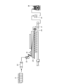
- FIG. 2 is a diagram showing an example of a specific configuration of a surge hopper.
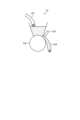
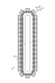
- FIG. 3 is a diagram showing an example of a specific configuration of a sintering machine.
- FIG. 4 is a diagram showing the insertion and discharge (cut-out) times of a raw material at each piece of equipment while the raw material is being transported from an upstream piece of equipment to a downstream piece of equipment in a manufacturing line.
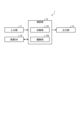
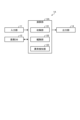
- FIG. 5 is a block diagram showing an example of a configuration of a process data editing device according to the embodiment.
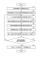
- FIG. 6 is a flowchart showing an example of the flow of a process data editing method according to the embodiment.
- FIG. 1 is a diagram showing an example of a steel sintering process line.
- FIG. 2 is a diagram showing an example of a specific configuration of a surge hopper.
- FIG. 3 is a diagram showing an example of a specific configuration of a
- FIG. 7 is a block diagram illustrating an example of the configuration of a process anomaly detection device according to the embodiment.
- FIG. 8 is an example of a method for editing process data according to an embodiment, and is a diagram showing an example of the configuration of a blending tank, a drum mixer, and a belt conveyor connecting them, and a method for calculating the actual moisture content of the raw materials in the drum mixer.
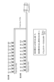
- Figure 9 shows an example of a method for editing process data according to an embodiment, where (a) is a diagram showing the relationship between the target moisture content and the actual moisture content when tracking according to the present invention is not performed, and (b) is a diagram showing the relationship between the target moisture content and the actual moisture content when tracking according to the present invention is performed.
- process data editing method process anomaly detection method, process data editing device, and process anomaly detection device according to the embodiments of the present invention will be described with reference to the drawings.
- the present invention is not limited to the following embodiments, and the components in the following embodiments include those that are replaceable and easy for a person skilled in the art, or those that are substantially the same.
- FIG. 1 (Overview of the sintering process)
- a steel sintering process line is a production line that links the raw material granulation process, sintering process, and cooling process, with a time constant of several hours.
- the raw materials are processed using equipment such as a blending tank 21 and a drum mixer 22.
- the raw materials are processed using equipment such as a surge hopper (raw material insertion device) 23, a sintering machine 24, an ignition furnace 25, and a crusher 26.
- the raw materials are processed using equipment such as a cooler 27 and a sieve 28. The raw materials processed by the sieve 28 are then fed into a blast furnace 29.
- a conveying device (belt conveyor) is provided between each piece of equipment to connect the pieces of equipment and transport the raw materials.
- the multiple pieces of equipment that perform predetermined processing on the raw materials and the conveying device that connects these multiple pieces of equipment and transports the raw materials are collectively referred to as "equipment.”
- the surge hopper 23 is equipped with a raw material supply port 231, a roll feeder 232, a main/split gate 233, and a raw material cut-out port 234.
- This surge hopper 23 cuts out a predetermined amount of granulated raw material and spreads it on the pallet 241 of the sintering machine 24 shown in FIG. 3.
- the surge hopper 23 since the surge hopper 23 has a mechanism for storing raw material, it has the characteristic that the time delay that occurs changes successively depending on the operating conditions.
- Figure 4 shows the time when raw materials are inserted and discharged (cut out) at each facility as they are transported from facility A on the upstream side to facility G on the downstream side.
- facilities A to G shown in the figure also include belt conveyors in addition to the various devices shown in Figure 1.
- the time when the raw material passes through the equipment is estimated by calculating the time delay correction amount from the operating status of each piece of equipment.
- data is generated on when and what process data was given to the raw materials transported to equipment G by the equipment upstream of it (e.g. equipment A-F), or when and what process data was measured by the upstream equipment.
- the time delay in the process data of each piece of equipment is corrected by tracing back to the upstream equipment while calculating the time from the insertion to the discharge of the raw materials at each piece of equipment, and each piece of process data is associated.
- process data refers to various data (various signals) acquired from each piece of equipment.
- This process data includes, for example, the settings (e.g., conveying speed, temperature, etc.) when processing raw materials in each piece of equipment, the measured values (e.g., temperature, etc.) from sensors attached to each piece of equipment, and the operation amounts (e.g., motor current value, etc.) given to each piece of equipment.
- process data may also include data on the quality (observation data such as moisture ratio and grain size) at a specific position of the raw materials conveyed to the sintering equipment, and the quality (analytical values such as strength and components) of the produced sintered ore.
- “Associating each process data” means associating the process data related to the raw materials inserted into equipment G, indicated by a star in Figure 4, with the process data related to the raw materials inserted into equipment upstream of that (e.g. equipment A to F). In doing so, the process data is associated with each other after correcting the time delay.
- the time from the insertion to the discharge of the raw materials in each equipment i.e., the residence time
- the time from the insertion to the discharge of the raw materials in each facility i.e., the time delay correction amount
- the time delay correction amount must be calculated taking into consideration the characteristics of the facility through which the raw materials pass and the operating status of that facility.
- the raw materials first extracted from the blending tank 21 are transported by a belt conveyor and inserted into the drum mixer 22 via multiple belt conveyors.
- the raw materials that have been converted into pseudo-particles by the drum mixer 22 are then transported again by the belt conveyor before being inserted into the surge hopper 23 and handed over to the subsequent firing process.
- the belt conveyor is controlled at a constant speed, the time from when the raw materials are inserted into the belt conveyor until they are discharged can be considered constant.
- the time from when the raw materials are inserted into the drum mixer 22 until they are discharged i.e., the residence time
- the residence time varies depending on the rotation speed of the drum, so it is necessary to calculate a time delay correction amount that takes this into account.
- the time delay correction amount is calculated using patterns 1 to 3, as shown in Table 1, depending on the type of facility through which the raw materials pass, i.e., the raw materials transport route.
- the time delay correction amount is calculated using the method of pattern 1 in Table 1.
- the time delay correction amount is calculated based on the relationship between the raw material transport speed and the equipment length. Also, the time when the value obtained by integrating (accumulating) the transport speed measured every moment reaches the equipment length is determined as the time when the raw materials are discharged from the equipment. Also, the difference between the time when the raw materials are discharged from the equipment and the time when they are inserted into the facility is the time delay correction amount.
- the time delay correction amount is calculated using the method of pattern 2 in Table 1.
- the time delay correction amount is calculated based on the relationship between the weight of the accumulated raw materials and the amount of raw materials inserted per unit time, or the relationship between the weight of the accumulated raw materials and the amount of raw materials discharged per unit time.
- the time delay correction amount is also calculated as the difference between the time of discharge from the equipment and the time of insertion into the facility.
- the time delay correction amount is calculated using the method of pattern 3 in Table 1.
- the time delay correction amount is calculated based on the rotation speed of the drum mixer 22 and the shape factor of the drum mixer 22.
- the shape factor of the drum mixer 22 is a coefficient proportional to the diameter of the drum mixer 22.
- FIG. 5 shows the configuration of an information processing device 1 that realizes the editing device for process data according to the embodiment.
- the information processing device 1 is realized by, for example, a general-purpose computer such as a workstation or a personal computer, or a server arranged on a cloud.
- the information processing device 1 also includes an input unit 11, an operation DB 12, a calculation unit 13, and an output unit 14.
- the input unit 11 is an input means for the calculation unit 13, and is realized by an input device such as a keyboard, a mouse pointer, or a numeric keypad.
- the input unit 11 inputs information necessary for various processes in the calculation unit 13.
- Operation DB12 stores process data acquired from each piece of equipment.
- this process data includes, for example, the operating conditions when processing raw materials at each piece of equipment (e.g., motor current values and other operating variables), the measured values of sensors attached to each piece of equipment (e.g., temperature, etc.), etc.
- the calculation unit 13 is realized by a processor such as a CPU (Central Processing Unit) and a memory (main memory unit) such as a RAM (Random Access Memory) or a ROM (Read Only Memory).
- a processor such as a CPU (Central Processing Unit) and a memory (main memory unit) such as a RAM (Random Access Memory) or a ROM (Read Only Memory).
- main memory unit such as a RAM (Random Access Memory) or a ROM (Read Only Memory).
- the calculation unit 13 loads a program into the working area of the main memory and executes it, and controls each component part through the execution of the program to realize functions that meet a predetermined purpose.
- the calculation unit 13 functions as a collection unit 131 and an editing unit 132 through the execution of the program.
- FIG. 5 shows an example in which the functions of each part are realized by one computer (calculation unit), the means for realizing the functions of each part is not particularly limited, and the functions of each part may be realized by multiple computers, for example.
- the collection unit 131 accesses the operation DB 12 and collects process data indicating the operating status of multiple pieces of equipment.
- the editing unit 132 correlates the process data collected by the collection unit 131 with the time delay corrected according to the type of equipment through which the raw materials pass on the production line.
- the collection unit 131 correlates the process data with each other after correcting the time delay. This makes it possible to look back and determine, for example, what state the raw materials were in at a certain point in the production process (what processing was performed on them) in equipment upstream of that point. Note that in this embodiment, the process data correlated with the time delay corrected in this way is also referred to as "tracked data.”
- the editing unit 132 corrects the time delay based on the raw material conveying speed of the conveying device and the equipment length of the conveying device, as shown in pattern 1 of Table 1 above. Then, the editing unit 132 associates each of the process data with the time delay corrected.
- the editing unit 132 corrects the time delay using the method shown in pattern 2 of Table 1 above. That is, the editing unit 132 corrects the time delay based on the weight of the raw materials accumulated in the equipment and the insertion speed of the raw materials at the inlet side of the equipment, or based on the weight of the raw materials accumulated in the equipment and the discharge speed of the raw materials at the outlet side of the equipment. Then, the editing unit 132 associates each of the process data with the time delay corrected.
- the editing unit 132 calculates the time delay correction amount based on the rotation speed of the drum mixer 22 and the shape factor of the drum mixer 22, as shown in pattern 3 of Table 1 above. Then, the editing unit 132 associates each of the process data with the time delay corrected.
- the editing unit 132 when focusing on a certain raw material, the editing unit 132 performs time delay correction and correlation for all process data from the upstream equipment that processed the raw material to the downstream equipment. This makes it easy to analyze the process data given to the raw material with respect to certain characteristics of a product or operation, for example.
- the output unit 14 is realized by a display device such as an LCD display or a CRT display.
- the output unit 14 outputs the tracked data edited by the editing unit 132, etc.
- Fig. 6 shows an example of details of a process performed by the editing unit 132 after the collection unit 131 collects process data.
- the equipment from which the search will begin is set (step S1).
- This "equipment from which the search will begin” refers to, for example, "equipment G" in FIG. 4.
- an arbitrary time to begin the search is set as the search start time (step S2).
- the equipment from which the search will begin and the search start time are set as in steps S1 and S2 in order to link, by tracking, the process data given to the material in the upstream equipment for the material that passed through the target equipment at the target time.
- the equipment one unit upstream of the equipment from which the search is to be started is set as the equipment to be searched for tracking (step S3).
- This "equipment to be searched” refers to, for example, "equipment F" in FIG. 4.
- the discharge time of the upstream equipment and the insertion time of the downstream equipment can be considered to be the same. Therefore, the discharge time of the equipment to be searched, which is one unit upstream of the equipment from which the search is to be started, is set as the search start time (step S4).
- step S5 the time delay correction amount for the equipment to be searched is calculated using one of the patterns 1 to 3 in Table 1 (step S5).
- step S6 the search start time is moved back by the time delay correction amount (step S6), and the moved back time is recorded as the insertion time of the equipment to be searched (step S7).
- step S8 it is determined whether the equipment to be searched is the final equipment in the search (step S8).
- step S8 if the equipment to be searched is not the final equipment in the search (No in step S8), the process returns to step S3, and the processes in steps S3 to S7 are repeated until the final equipment in the search is reached.
- step S8 if the equipment to be searched is the final equipment in the search (Yes in step S8), the following process is performed.
- FIG. 7 shows the configuration of an information processing device 1A that realizes the process anomaly detection device according to the embodiment.
- the information processing device 1A is realized by, for example, a general-purpose computer such as a workstation or a personal computer, or a server arranged on a cloud.
- the information processing device 1A also includes an input unit 11, an operation DB 12, a calculation unit 13A, and an output unit 14.
- the input unit 11, the operation DB 12, and the output unit 14 are the same as those of the information processing device 1 described above, and therefore description thereof will be omitted.
- the calculation unit 13A is realized by a processor such as a CPU, and a memory (main storage unit) such as a RAM or ROM.
- the calculation unit 13A loads a program into the working area of the main storage unit, executes it, and realizes functions that meet a predetermined purpose by controlling each component through the execution of the program.
- the calculation unit 13A functions as a collection unit 131, an editing unit 132, and an anomaly detection unit 133 through the execution of the program.
- FIG. 7 shows an example in which the functions of each unit are realized by one computer (calculation unit), the means for realizing the functions of each unit is not particularly limited, and the functions of each unit may be realized by multiple computers, for example.
- the collection unit 131 and the editing unit 132 are the same as those of the calculation unit 13 described above, and therefore their explanations are omitted.
- the anomaly detection unit 133 performs anomaly diagnosis to detect anomalies in the quality or productivity of raw materials on the production line based on the process data for which the time delay has been corrected in the editing unit 132.
- An anomaly diagnosis is a method in which a prediction model that predicts specific process data based on other process data is constructed in advance, and the prediction error, which is the difference between the predicted value of the process data based on the prediction model and its actual value, is evaluated.
- Another anomaly diagnosis method is to detect anomalies by evaluating the degree of deviation of each process data from normal times.
- the abnormality detection unit 133 predefines abnormality monitoring items and abnormality diagnosis methods as described above, and detects the presence or absence of an abnormality for each abnormality monitoring item. In addition, if there is a problem with the quality of the raw material currently being processed in the sieve 28 (or the crusher 26, drum mixer 22, etc.), the abnormality detection unit 133 can also check the condition of the raw material in the equipment upstream and identify the cause.
- a process anomaly diagnosis method (Method of detecting abnormalities in a process) A process anomaly diagnosis method according to the embodiment will be described.
- an anomaly in the quality or productivity of raw materials in a production line is detected based on the process data in which the time delay has been corrected by the above-mentioned method for editing process data.
- an example of the above production line is a sintering process line in a steelworks.
- the above-mentioned process data editing method is used to associate data that has a physical and spatial spread from upstream to downstream equipment with data that indicates the state of each piece of equipment or the state of raw materials based on the amount of time delay.
- the process anomaly detection method according to the embodiment can also use such a data set to build a predictive model required for anomaly detection.
- the current value of the raw material transport belt conveyor in front of the sintering plant depends on the amount of raw material on the belt conveyor. Therefore, it is possible to predict the current value from the weight of each raw material by synchronizing the timing of the multiple raw materials that are cut out and taking into account the transport time to each motor position. It is possible to detect abnormalities in the belt conveyor motor or the belt conveyor itself based on the prediction error between the current predicted value and the actual current value using this prediction model. In addition, operational abnormality detection using a prediction model of the raw material moisture content in the drum mixer 22, which will be described later, is also performed based on data that has been edited with time delay correction. It is also possible to predict the quality, including the strength, of the produced sintered ore and detect quality abnormalities based on the prediction error.
- the data set obtained by this embodiment can achieve its effect by focusing on the relationship (correlation, etc.) between multiple variables.
- Possible methods of detecting anomalies include a method of detecting anomalies by evaluating the degree of deviation between a predicted amount and an actual value, or the degree of deviation between a predicted amount and a target value, based on a prediction model that predicts equipment conditions, etc., constructed using data from normal times, and anomaly detection based on principal component analysis, etc.
- the prediction model used for anomaly detection is not limited to a method based on a statistical method such as machine learning, but may be constructed using a method based on a scientific approach such as a physical model.
- the process anomaly detection method performs anomaly detection by taking into account the effect of the time delay from the upstream equipment to the downstream equipment, so that the variation in data that depends on the time delay can be suppressed, enabling accurate anomaly detection.
- Identifying the cause of the abnormality When an anomaly is detected based on a prediction error, it is possible to identify the process data that is the explanatory variable that contributes to the prediction error and to clearly indicate it as a candidate for the cause of the anomaly. It is also possible to extract candidate anomaly signals by evaluating the degree of deviation from the normal state of each explanatory variable. This makes it possible to quickly identify the cause of an abnormal operation, minimize the impact of the abnormal operation on product quality, and shorten the time it takes to restore the normal state, thereby contributing to maintaining production speed and product quality.
- Figure 8 shows an example of the configuration of blending tanks #1 to #20, drum mixers, and belt conveyors 1 to 3 connecting them, and a method for calculating the moisture content (effective moisture content) of the raw materials in the drum mixer.
- the raw materials used in the sintering process are stored in multiple blending tanks, and are extracted from the multiple blending tanks and granulated for use, taking into consideration the raw material blend and production schedule.
- the amount of raw material extracted from each blending tank is measured for each tank by a weighing machine attached to each tank.
- the moisture content in each tank is also measured for each tank by a moisture meter attached to each tank.
- the raw materials discharged from the blending tank are granulated by spraying water and stirring in a drum mixer. To optimize this granulation, it is necessary to maintain an appropriate moisture content, and it is necessary to manage the target and actual moisture content values.
- the actual moisture content of the raw materials is calculated using the formula shown at the bottom of Figure 8. Meanwhile, the weighing machines and moisture content meters installed in each blending tank are located physically away from the drum mixer. Therefore, by utilizing this invention, process data that indicates the operating status of each piece of equipment that makes up the entire process is continuously collected, and tracked data is created by correlating the process data with time delay corrections according to the raw material transport route.
- the delay time from the downstream equipment, the drum mixer, to the upstream equipment, the blending tank #1 is 30 minutes.
- the actual moisture content of the raw material in the current drum mixer is linked to the amount of raw material discharged and the moisture content in blending tank #1 30 minutes prior.
- the discharge amounts and moisture contents of the other blending tanks #2 to #20 are also linked to the actual moisture content of the drum mixer to create tracked data.
- the conveying speeds of belt conveyors 1 to 3 are different, this is also taken into account to correct the time delay and create tracked data.
- the present invention by accurately calculating the real moisture content as described above, it is also possible to perform anomaly detection to prevent the real moisture content from deviating from the target moisture content. In this case, by using the present invention, it is expected that anomaly detection will be improved, leading to stable production and quality of raw materials.
- process anomaly detection method process data editing device, and process anomaly detection device according to the embodiments described above, it is possible to correlate various process data in a manufacturing line with time delays corrected.
- the process data in which the time delays have been corrected and which has been appropriately correlated can be used for data analysis, quality control, equipment maintenance, etc., and can be used for monitoring the entire process, detecting anomalies, optimization, etc.
Landscapes
- Engineering & Computer Science (AREA)
- Chemical & Material Sciences (AREA)
- Manufacturing & Machinery (AREA)
- Materials Engineering (AREA)
- Metallurgy (AREA)
- Geochemistry & Mineralogy (AREA)
- General Life Sciences & Earth Sciences (AREA)
- Environmental & Geological Engineering (AREA)
- Life Sciences & Earth Sciences (AREA)
- Mechanical Engineering (AREA)
- Geology (AREA)
- Organic Chemistry (AREA)
- General Engineering & Computer Science (AREA)
- Quality & Reliability (AREA)
- Physics & Mathematics (AREA)
- General Physics & Mathematics (AREA)
- Automation & Control Theory (AREA)
- Manufacture And Refinement Of Metals (AREA)
Abstract
Description
まず、実施形態に係るプロセスデータの編集方法が適用される高炉鉄鋼業の焼結プロセスの概要について、図1~図4を参照しながら説明する。
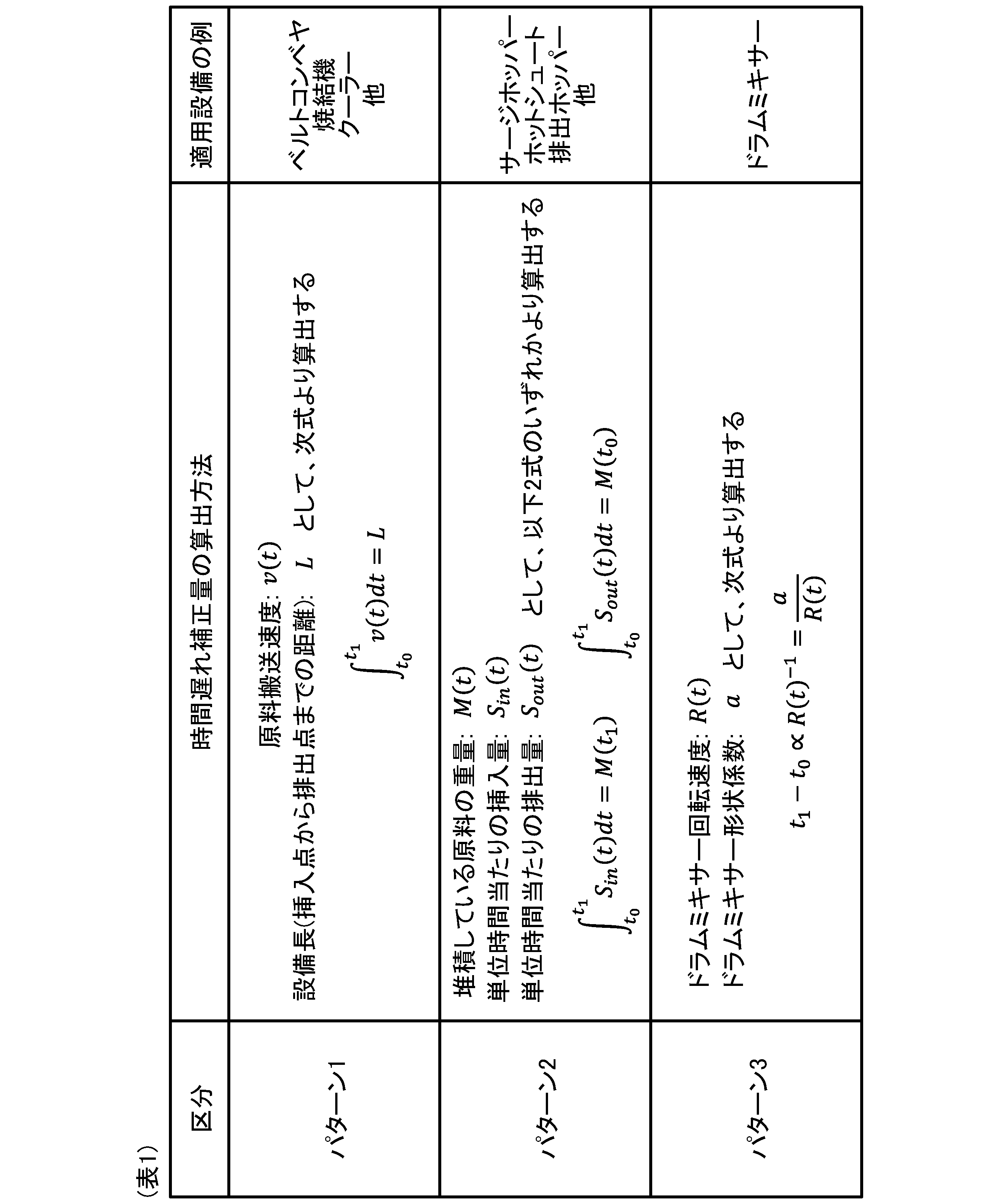
例えばベルトコンベヤ、焼結機24、クーラー27等のように、モータ等の駆動装置によって原料を搬送する設備では、表1のパターン1の方法を用いて時間遅れ補正量を算出する。この方法では、原料の搬送速度と設備長との関係に基づいて、時間遅れ補正量を算出する。また、刻一刻と計測される搬送速度を時間積分(積算)した値が設備長に達した時点を、原料が当該設備から排出される時刻として決定する。また、当該設備からの排出時刻と当該施設への挿入時刻の差が、時間遅れ補正量となる。
例えばサージホッパー23、ホットシュート、排出ホッパー等のように、原料を堆積させる設備では、表1のパターン2の方法を用いて時間遅れ補正量を算出する。この方法では、堆積している原料の重量と単位時間当たりの原料の挿入量との関係、または堆積している原料の重量と単位時間当たりの原料の排出量との関係に基づいて、時間遅れ補正量を算出する。また、当該設備からの排出時刻と当該施設への挿入時刻の差が、時間遅れ補正量となる。
例えばドラムミキサー22では、表1のパターン3の方法を用いて時間遅れ補正量を算出する。この方法では、ドラムミキサー22の回転速度とドラムミキサー22の形状係数とに基づいて、時間遅れ補正量を算出する。なお、ドラムミキサー22の形状係数は、ドラムミキサー22の直径に比例する係数である。
続いて、実施形態に係るプロセスデータの編集装置の構成の一例について、図5を参照しながら説明する。同図は、実施形態に係るプロセスデータの編集装置を実現する情報処理装置1の構成を示している。この情報処理装置1は、例えばワークステーションやパソコン等の汎用コンピュータ、あるいはクラウド上に配置されたサーバ等により実現される。また、情報処理装置1は、入力部11と、操業DB12と、演算部13と、出力部14と、を備えている。
実施形態に係るプロセスデータの編集方法の一例について、図4および図6を参照しながら説明する。図6は、収集部131によってプロセスデータを収集した後に、編集部132が実施する処理の詳細の一例を示している。
実施形態に係るプロセスの異常検知装置の構成の一例について、図7を参照しながら説明する。同図は、実施形態に係るプロセスの異常検知装置を実現する情報処理装置1Aの構成を示している。この情報処理装置1Aは、例えばワークステーションやパソコン等の汎用コンピュータ、あるいはクラウド上に配置されたサーバ等により実現される。また、情報処理装置1Aは、入力部11と、操業DB12と、演算部13Aと、出力部14と、を備えている。情報処理装置1Aの構成のうち、入力部11、操業DB12および出力部14は前記した情報処理装置1と同様であるため、説明を省略する。
実施形態に係るプロセスの異常診断方法について説明する。実施形態に係るプロセスの異常検知方法では、前記したプロセスデータの編集方法によって時間遅れが補正されたプロセスデータに基づいて、製造ラインにおける原料の品質または生産性に対する異常を検知する。また、上記の製造ラインとしては、例えば製鉄所の焼結プロセスライン等が挙げられる。
予測誤差に基づいて異常検知された場合は、予測誤差に寄与する説明変数であるプロセスデータを特定し、異常原因の候補として明示することも可能である。また、各説明変数の正常状態からの逸脱度を評価して異常候補信号を抽出することも可能である。これにより、操業異常の原因を速やかに特定し、異常操業による製品品質への影響を最小限とし、正常な状態への復旧の短縮化を図り、生産速度の維持や製品品質の維持に貢献することができる。
本発明に係るプロセスデータの編集方法の実施例について、図8および図9を参照しながら説明する。図8は、配合槽♯1~♯20、ドラムミキサーおよびそれらを連結するベルトコンベヤ1~3の構成例と、ドラムミキサー内における原料の水分率(実質水分率)の算出方法とを示している。
11 入力部
12 操業DB
13,13A 演算部
131 収集部(収集手段)
132 編集部(編集手段)
133 異常検知部(異常検知手段)
14 出力部
21 配合槽
22 ドラムミキサー
23 サージホッパー(原料挿入装置)
231 原料供給口
232 ロールフィーダ
233 主/分割ゲート
234 原料切出口
24 焼結機
241 パレット
25 点火炉
26 粉砕機
27 クーラー(冷却器)
28 篩
29 高炉
Claims (9)
- 原料に所定の処理を施す複数の機器と、前記複数の機器を連結して前記原料を搬送する搬送装置とからなる複数の設備で構成される製造ラインにおいて、
コンピュータが備える収集手段が、前記複数の設備の稼働状態を示すプロセスデータを収集する収集ステップと、
前記コンピュータが備える編集手段が、前記プロセスデータについて、前記製造ラインで前記原料が経由する設備の種類に応じて時間遅れを補正して関連付ける編集ステップと、
を含むプロセスデータの編集方法。 - 前記編集ステップは、前記原料が経由する設備に前記搬送装置が含まれる場合、前記搬送装置による原料の搬送速度と、前記搬送装置の設備長とに基づいて、前記時間遅れを補正する請求項1に記載のプロセスデータの編集方法。
- 前記編集ステップは、前記原料が経由する設備に前記原料を堆積させる機器が含まれる場合、堆積している前記原料の重量と設備入側における前記原料の挿入速度とに基づいて、または堆積している前記原料の重量と設備出側における前記原料の排出速度とに基づいて、前記時間遅れを補正する請求項1に記載のプロセスデータの編集方法。
- 原料に所定の処理を施す複数の機器と、前記複数の機器を連結して前記原料を搬送する搬送装置とからなる複数の設備で構成される製造ラインにおいて、
コンピュータが備える収集手段が、前記複数の設備の稼働状態を示すプロセスデータを収集する収集ステップと、
前記コンピュータが備える編集手段が、前記プロセスデータについて、前記製造ラインで前記原料が経由する設備の種類に応じて時間遅れを補正して関連付ける編集ステップと、
前記コンピュータが備える異常検知手段が、時間遅れが補正された前記プロセスデータに基づいて、製造ラインにおける原料の品質または生産性に対する異常を検知する異常検知ステップと、
を含むプロセスの異常検知方法。 - 前記製造ラインは、製鉄所の焼結プロセスラインである請求項4に記載のプロセスの異常検知方法。
- 原料に所定の処理を施す複数の機器と、前記複数の機器を連結して前記原料を搬送する搬送装置とからなる複数の設備で構成される製造ラインにおいて、
前記複数の設備の稼働状態を示すプロセスデータを収集する収集手段と、
前記プロセスデータについて、前記製造ラインで前記原料が経由する設備の種類に応じて時間遅れを補正して関連付ける編集手段と、
を含むプロセスデータの編集装置。 - 前記編集手段は、前記原料が経由する設備に前記搬送装置が含まれる場合、前記搬送装置による原料の搬送速度と、前記搬送装置の設備長とに基づいて、前記時間遅れを補正する請求項6に記載のプロセスデータの編集装置。
- 前記編集手段は、前記原料が経由する設備に前記原料を堆積させる機器が含まれる場合、堆積している前記原料の重量と設備入側における前記原料の挿入速度とに基づいて、または堆積している前記原料の重量と設備出側における前記原料の排出速度とに基づいて、前記時間遅れを補正する請求項6に記載のプロセスデータの編集装置。
- 原料に所定の処理を施す複数の機器と、前記複数の機器を連結して前記原料を搬送する搬送装置とからなる複数の設備で構成される製造ラインにおいて、
前記複数の設備の稼働状態を示すプロセスデータを収集する収集手段と、
前記プロセスデータについて、前記製造ラインで前記原料が経由する設備の種類に応じて時間遅れを補正して関連付ける編集手段と、
時間遅れが補正された前記プロセスデータに基づいて、製造ラインにおける原料の品質または生産性に対する異常を検知する異常検知手段と、
を備えるプロセスの異常検知装置。
Priority Applications (4)
| Application Number | Priority Date | Filing Date | Title |
|---|---|---|---|
| JP2024550794A JP7722596B2 (ja) | 2023-07-05 | 2024-07-02 | プロセスデータの編集方法、プロセスの異常検知方法、プロセスデータの編集装置およびプロセスの異常検知装置 |
| CN202480043953.8A CN121464406A (zh) | 2023-07-05 | 2024-07-02 | 工艺数据的编辑方法、工艺的异常检测方法、工艺数据的编辑装置以及工艺的异常检测装置 |
| KR1020267002008A KR20260026561A (ko) | 2023-07-05 | 2024-07-02 | 프로세스 데이터의 편집 방법, 프로세스의 이상 검지 방법, 프로세스 데이터의 편집 장치 및 프로세스의 이상 검지 장치 |
| EP24836042.2A EP4722833A1 (en) | 2023-07-05 | 2024-07-02 | Process data editing method, process abnormality detection method, process data editing device, and process abnormality detection device |
Applications Claiming Priority (2)
| Application Number | Priority Date | Filing Date | Title |
|---|---|---|---|
| JP2023110832 | 2023-07-05 | ||
| JP2023-110832 | 2023-07-05 |
Publications (1)
| Publication Number | Publication Date |
|---|---|
| WO2025009529A1 true WO2025009529A1 (ja) | 2025-01-09 |
Family
ID=94171503
Family Applications (1)
| Application Number | Title | Priority Date | Filing Date |
|---|---|---|---|
| PCT/JP2024/023935 Ceased WO2025009529A1 (ja) | 2023-07-05 | 2024-07-02 | プロセスデータの編集方法、プロセスの異常検知方法、プロセスデータの編集装置およびプロセスの異常検知装置 |
Country Status (5)
| Country | Link |
|---|---|
| EP (1) | EP4722833A1 (ja) |
| JP (1) | JP7722596B2 (ja) |
| KR (1) | KR20260026561A (ja) |
| CN (1) | CN121464406A (ja) |
| WO (1) | WO2025009529A1 (ja) |
Citations (5)
| Publication number | Priority date | Publication date | Assignee | Title |
|---|---|---|---|---|
| JPH042732A (ja) * | 1990-04-20 | 1992-01-07 | Nippon Steel Corp | 焼結プロセス制御装置 |
| JP2011084758A (ja) | 2009-10-13 | 2011-04-28 | Kobe Steel Ltd | 測定データ収集方法及び測定データ収集システム |
| JP2013122341A (ja) | 2011-12-12 | 2013-06-20 | Nippon Steel & Sumitomo Metal Corp | 焼結機のパレットのデータ測定装置およびデータ測定方法 |
| JP2018180666A (ja) * | 2017-04-05 | 2018-11-15 | オムロン株式会社 | 制御装置、制御プログラム、制御システム、および、制御方法 |
| JP2021086457A (ja) * | 2019-11-28 | 2021-06-03 | 花王株式会社 | 品質計測方法及び品質計測装置 |
-
2024
- 2024-07-02 KR KR1020267002008A patent/KR20260026561A/ko active Pending
- 2024-07-02 WO PCT/JP2024/023935 patent/WO2025009529A1/ja not_active Ceased
- 2024-07-02 JP JP2024550794A patent/JP7722596B2/ja active Active
- 2024-07-02 CN CN202480043953.8A patent/CN121464406A/zh active Pending
- 2024-07-02 EP EP24836042.2A patent/EP4722833A1/en active Pending
Patent Citations (5)
| Publication number | Priority date | Publication date | Assignee | Title |
|---|---|---|---|---|
| JPH042732A (ja) * | 1990-04-20 | 1992-01-07 | Nippon Steel Corp | 焼結プロセス制御装置 |
| JP2011084758A (ja) | 2009-10-13 | 2011-04-28 | Kobe Steel Ltd | 測定データ収集方法及び測定データ収集システム |
| JP2013122341A (ja) | 2011-12-12 | 2013-06-20 | Nippon Steel & Sumitomo Metal Corp | 焼結機のパレットのデータ測定装置およびデータ測定方法 |
| JP2018180666A (ja) * | 2017-04-05 | 2018-11-15 | オムロン株式会社 | 制御装置、制御プログラム、制御システム、および、制御方法 |
| JP2021086457A (ja) * | 2019-11-28 | 2021-06-03 | 花王株式会社 | 品質計測方法及び品質計測装置 |
Also Published As
| Publication number | Publication date |
|---|---|
| EP4722833A1 (en) | 2026-04-08 |
| JP7722596B2 (ja) | 2025-08-13 |
| KR20260026561A (ko) | 2026-02-26 |
| JPWO2025009529A1 (ja) | 2025-01-09 |
| CN121464406A (zh) | 2026-02-03 |
Similar Documents
| Publication | Publication Date | Title |
|---|---|---|
| CN114144738B (zh) | 品质预测模型生成方法、品质预测模型、品质预测方法、金属材料的制造方法、品质预测模型生成装置以及品质预测装置 | |
| Lee et al. | Process mean and screening limits for filling processes under two-stage screening procedure | |
| JP2009282740A (ja) | 製品品質予測および制御方法 | |
| JP7031512B2 (ja) | 鉄鋼プラント用監視作業支援システム | |
| CN106794499A (zh) | 材料特性值推定方法、材料特性值推定装置、及钢带的制造方法 | |
| JP7725927B2 (ja) | 成形管理装置 | |
| JP5821363B2 (ja) | 製品欠陥要因分析装置 | |
| US10095199B2 (en) | Energy consumption predicting device for rolling line | |
| JP5888175B2 (ja) | データ解析装置 | |
| KR101801897B1 (ko) | 제품 품질 관리를 위한 공정 관리 시스템 및 그 관리 방법 | |
| JP7722596B2 (ja) | プロセスデータの編集方法、プロセスの異常検知方法、プロセスデータの編集装置およびプロセスの異常検知装置 | |
| CN109948746B (zh) | 一种基于传感器的钢坯信息追溯方法 | |
| CN105903768A (zh) | 制钢成套设备的趋势监测装置 | |
| JP7135962B2 (ja) | 鋼板の仕上出側温度制御方法、鋼板の仕上出側温度制御装置、及び鋼板の製造方法 | |
| JP4647809B2 (ja) | 生産管理システム | |
| JP5007630B2 (ja) | 製品品質の制御方法及び制御装置 | |
| TWI654043B (zh) | 分割切斷控制裝置 | |
| JP4718287B2 (ja) | 圧延ライン管理システム | |
| JP7029647B2 (ja) | コントローラ、システム、方法及びプログラム | |
| CN120850018B (zh) | 基于联合机器学习模型的饲料产线监测控制方法及系统 | |
| JP7151636B2 (ja) | データ収集装置 | |
| Prakoso et al. | Measurement of Machine Effectiveness Using the Overall Equipment Effectiveness (OEE) Value Approach on the BX-75 Machine (A Case Study) | |
| JP6822390B2 (ja) | 厚鋼板の粗圧延時間算出方法、厚鋼板の粗圧延時間算出装置、及び厚鋼板の製造方法 | |
| EP4674991A1 (en) | Method and device for detecting air leak in sintering machine pallet | |
| Hijriah et al. | Effect of Raw Material Inventory, Workers Quantity, and The Capacity of Machine on The Volume of The Production (Case on Nickel Pig Iron PT. Cahaya Modern Metal Industry) |
Legal Events
| Date | Code | Title | Description |
|---|---|---|---|
| WWE | Wipo information: entry into national phase |
Ref document number: 2024550794 Country of ref document: JP |
|
| 121 | Ep: the epo has been informed by wipo that ep was designated in this application |
Ref document number: 24836042 Country of ref document: EP Kind code of ref document: A1 |
|
| WWE | Wipo information: entry into national phase |
Ref document number: 202517127069 Country of ref document: IN |
|
| WWE | Wipo information: entry into national phase |
Ref document number: 2024836042 Country of ref document: EP |
|
| REG | Reference to national code |
Ref country code: BR Ref legal event code: B01A Ref document number: 112025029376 Country of ref document: BR |
|
| WWP | Wipo information: published in national office |
Ref document number: 202517127069 Country of ref document: IN |
|
| ENP | Entry into the national phase |
Ref document number: 2024836042 Country of ref document: EP Effective date: 20251230 |
|
| ENP | Entry into the national phase |
Ref document number: 1020267002008 Country of ref document: KR Free format text: ST27 STATUS EVENT CODE: A-0-1-A10-A15-NAP-PA0105 (AS PROVIDED BY THE NATIONAL OFFICE) |
|
| WWE | Wipo information: entry into national phase |
Ref document number: 1020267002008 Country of ref document: KR |
|
| ENP | Entry into the national phase |
Ref document number: 2024836042 Country of ref document: EP Effective date: 20251230 |
|
| ENP | Entry into the national phase |
Ref document number: 2024836042 Country of ref document: EP Effective date: 20251230 |
|
| NENP | Non-entry into the national phase |
Ref country code: DE |
|
| ENP | Entry into the national phase |
Ref document number: 2024836042 Country of ref document: EP Effective date: 20251230 |
|
| WWP | Wipo information: published in national office |
Ref document number: 1020267002008 Country of ref document: KR |
|
| WWP | Wipo information: published in national office |
Ref document number: 2024836042 Country of ref document: EP |