WO2025009523A1 - 制御システム、及び制御方法 - Google Patents
制御システム、及び制御方法 Download PDFInfo
- Publication number
- WO2025009523A1 WO2025009523A1 PCT/JP2024/023917 JP2024023917W WO2025009523A1 WO 2025009523 A1 WO2025009523 A1 WO 2025009523A1 JP 2024023917 W JP2024023917 W JP 2024023917W WO 2025009523 A1 WO2025009523 A1 WO 2025009523A1
- Authority
- WO
- WIPO (PCT)
- Prior art keywords
- counter
- counter value
- sensor
- control system
- acquisition unit
- Prior art date
- Legal status (The legal status is an assumption and is not a legal conclusion. Google has not performed a legal analysis and makes no representation as to the accuracy of the status listed.)
- Ceased
Links
Images







Classifications
-
- G—PHYSICS
- G01—MEASURING; TESTING
- G01S—RADIO DIRECTION-FINDING; RADIO NAVIGATION; DETERMINING DISTANCE OR VELOCITY BY USE OF RADIO WAVES; LOCATING OR PRESENCE-DETECTING BY USE OF THE REFLECTION OR RERADIATION OF RADIO WAVES; ANALOGOUS ARRANGEMENTS USING OTHER WAVES
- G01S7/00—Details of systems according to groups G01S13/00, G01S15/00, G01S17/00
- G01S7/48—Details of systems according to groups G01S13/00, G01S15/00, G01S17/00 of systems according to group G01S17/00
- G01S7/497—Means for monitoring or calibrating
-
- G—PHYSICS
- G01—MEASURING; TESTING
- G01S—RADIO DIRECTION-FINDING; RADIO NAVIGATION; DETERMINING DISTANCE OR VELOCITY BY USE OF RADIO WAVES; LOCATING OR PRESENCE-DETECTING BY USE OF THE REFLECTION OR RERADIATION OF RADIO WAVES; ANALOGOUS ARRANGEMENTS USING OTHER WAVES
- G01S17/00—Systems using the reflection or reradiation of electromagnetic waves other than radio waves, e.g. lidar systems
- G01S17/87—Combinations of systems using electromagnetic waves other than radio waves
-
- G—PHYSICS
- G01—MEASURING; TESTING
- G01S—RADIO DIRECTION-FINDING; RADIO NAVIGATION; DETERMINING DISTANCE OR VELOCITY BY USE OF RADIO WAVES; LOCATING OR PRESENCE-DETECTING BY USE OF THE REFLECTION OR RERADIATION OF RADIO WAVES; ANALOGOUS ARRANGEMENTS USING OTHER WAVES
- G01S7/00—Details of systems according to groups G01S13/00, G01S15/00, G01S17/00
- G01S7/48—Details of systems according to groups G01S13/00, G01S15/00, G01S17/00 of systems according to group G01S17/00
- G01S7/483—Details of pulse systems
- G01S7/484—Transmitters
Definitions
- This disclosure relates to a control system and a control method.
- Patent Document 1 discloses a distance measuring device.
- This distance measuring device includes a light emitting unit that irradiates an object with light, a light receiving unit that receives reflected light from the object, a distance calculation unit that calculates the distance to the object from the output signal of the light receiving unit, and a control unit that controls the light emitting unit and the light receiving unit, and determines whether there is interference from other distance measuring devices from the distance calculation result by the distance calculation unit.
- the present disclosure aims to provide a control system etc. that can adjust the operation timing of a sensor without wiring a signal line for adjusting the timing.
- a control system is a control system provided for each of a plurality of sensors in a detection system that detects an object using the plurality of sensors, and includes a counter that outputs an operation signal for operating a corresponding sensor according to a counter value, a first acquisition unit that acquires time information shared by each of the plurality of sensors, a second acquisition unit that acquires the counter value of the counter at the time when the first acquisition unit acquires the time information, and a processing unit, and the processing unit executes an adjustment process that adjusts the timing of outputting the operation signal based on the time information acquired by the first acquisition unit and the counter value acquired by the second acquisition unit.
- a control method is a control method executed by each of a plurality of sensors in a detection system that detects an object using the plurality of sensors, which acquires time information shared by each of the plurality of sensors, acquires the counter value of a counter that outputs an operation signal for operating a corresponding sensor according to the counter value at the time when the time information was acquired, and executes an adjustment process that adjusts the timing of outputting the operation signal based on the acquired time information and the acquired counter value.
- the control system has the advantage that it is possible to adjust the operation timing of the sensor without wiring a signal line for adjusting the timing.
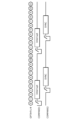
- FIG. 1 is an explanatory diagram of a case where the operations of a plurality of sensors interfere with each other.
- FIG. 2 is an explanatory diagram of a case where the operations of a plurality of sensors do not interfere with each other.
- FIG. 3 is an explanatory diagram of the problem with the sensor of the comparative example.
- FIG. 4 is a schematic diagram showing an overall configuration including a control system according to an embodiment.
- FIG. 5 is a diagram illustrating an example of the operation of the counter according to the embodiment.
- FIG. 6 is a schematic diagram illustrating an example of the operation of the control system according to the embodiment.
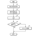
- FIG. 7 is a flowchart showing an example of the operation of the control system according to the embodiment.
- FIG. 8 is a diagram illustrating an example of a program related to the adjustment process executed by the control system according to the embodiment.
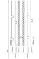
- FIG. 9 is a diagram showing an example of the operation of each sensor when there is no deviation in the counter.
- FIG. 10 is a diagram showing an example of the operation of each sensor when there is a deviation in the counter.
- FIG. 11 is a diagram showing an example of adjustment of the operation timing of the sensor when there is a deviation in the counter.
- FIG. 12 is a schematic diagram showing an overall configuration including a control system according to a modified example of the embodiment.
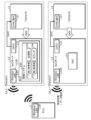
- FIG. 13 is a schematic diagram showing an overall configuration including a control system according to another modified example of the embodiment.
- a system that detects an object by using a plurality of sensors for detecting the object, such as a TOF (Time Of Flight) camera.
- a TOF Time Of Flight
- the accuracy of detecting the object decreases due to interference between the sensors.
- interference refers to a state in which, when the sensor is a TOF camera, the sensor receives light emitted by a sensor other than the sensor.
- FIG. 1 is an explanatory diagram of a case where the operations of multiple sensors interfere with each other.
- “Sensor1 state” represents the state of one of the two sensors (here, a TOF camera), and “Sensor2 state” represents the state of the other sensor.
- “emission/exposure” represents the light emission period and exposure period of the sensor
- “readout” represents the period during which image data is read from the sensor
- “nop” represents the standby period.
- the light emission period and exposure period of "Sensor1” overlap with the light emission period and exposure period of "Sensor2," and the operations of "Sensor1” and “Sensor2” interfere with each other.
- FIG. 2 is an explanatory diagram of a case where the operations of multiple sensors do not interfere with each other.
- SYNC represents a synchronization signal. Note that a description of the points in Figure 2 that are common to Figure 1 will be omitted.
- One possible method for providing a synchronization signal to each sensor is to connect a device such as a sync generator to each sensor via a dedicated line, as shown in Figure 3, and then transmit a synchronization signal to each sensor via the dedicated line.
- this method has the following problems:
- FIG. 3 is an explanatory diagram of the problem with the sensor 200 of the comparative example.
- there are two sensors 200 of the comparative example one sensor 200A is also called “Sensor 1" and the other sensor 200B is also called “Sensor 2".
- Each sensor 200 has a functional unit 210 that functions as a TOF camera, and a processing unit 220 that processes image data from the functional unit 210 and transmits it to an ECU (Electronic Control Unit) 300.
- the processing unit 220 is configured, for example, by a SoC (System on Chip) board.
- the ECU 300 executes various processes based on the data (object detection results) transmitted from each sensor 200.
- the sensors 200A and 200B are each connected to a sync generator 400 that generates a synchronization signal ("sync" in FIG. 3) via a dedicated line, and are synchronized by the synchronization signal transmitted from the sync generator 400.
- a dedicated line must be wired from the sync generator 400 to each sensor 200.
- it may be difficult to wire the dedicated line which may limit the installation position of each sensor 200.
- the present disclosure aims to provide a control system etc. that can synchronize sensors without wiring dedicated lines as described above, in other words, can adjust the operation timing of sensors without wiring signal lines for timing adjustment.
- FIG. 4 is a schematic diagram showing an overall configuration including a control system 100 according to the embodiment.
- the control system 100 is used in a detection system that detects an object using a plurality of (here, two) sensors 1, and is mounted on each sensor 1.
- sensor 1A or "Sensor 1”
- sensor 1B or "Sensor 2”
- the control system 100 can also be used for a detection system in which the number of sensors 1 is three or more.
- each sensor 1 is a TOF camera.
- Each sensor 1 includes a functional unit 11 that functions as a TOF camera, and a processing unit 12 that processes image data from the functional unit 11 and transmits it to the ECU 2.
- the functional unit 11 and the processing unit 12 are connected to each other by internal wiring. Note that the internal wiring is different from the dedicated line described above, being wired inside each sensor 1 and is not wired to be connected to an external device such as a sink generator.
- the functional unit 11 has a terminal 111.
- the terminal 111 is connected to a first terminal 121 (described later) of the processing unit 12 via internal wiring, and receives an operation signal ("sync" in FIG. 4) transmitted from the processing unit 12.
- the operation signal is a signal that causes counter 104 (described later) to operate the corresponding sensor 1 in accordance with the counter value.
- counter 104 provided in sensor 1A (“Sensor1”) outputs an operation signal for operating sensor 1A.
- counter 104 provided in sensor 1B (“Sensor2”) outputs an operation signal for operating sensor 1B.
- the operation signal is a falling pulse that is generated at the timing for operating the corresponding sensor 1.
- the functional unit 11 operates at a timing according to the operation signal received via the terminal 111. Specifically, the functional unit 11 starts light emission and exposure each time it receives a falling pulse, which is an operation signal, and then executes a series of processes to read out image data and send it to the processing unit 12.
- the processing unit 12 is configured with a SoC board and has a first terminal 121, a second terminal 122, and a SoC 123.
- the first terminal 121 is a GPIO (General-Purpose Input/Output) terminal, and is connected to the terminal 111 of the functional unit 11 via internal wiring.
- the first terminal 121 transmits an operation signal output by the counter 104 (described later) of the SoC 123 to the terminal 111 of the functional unit 11.
- the second terminal 122 is a terminal for wired communication that complies with the Ethernet standard, and is connected to the terminal 21 of the ECU 2 via an Ethernet cable.
- the second terminal 122 transmits data (object detection results) processed by the SoC 123 to the terminal 21 of the ECU 2.
- the second terminal 122 also receives time information (described later) transmitted from the ECU 2.
- the ECU 2 When the ECU 2 receives data (object detection results) transmitted from each sensor 1 via the terminal 21, it executes various processes based on the received data from each sensor 1.
- the ECU 2 also transmits time data to each sensor 1 via the terminal 21.
- the time data is synchronized time data received by the ECU 2 from an NTP (Network Time Protocol) server, for example. Therefore, each sensor 1 can share the synchronized time by receiving the time data transmitted from the ECU 2.
- NTP Network Time Protocol
- SoC123 executes various processes of the sensor 1.
- SoC123 is equipped with a computer including a processor and memory.
- the memory is a ROM (Read Only Memory) or a RAM (Random Access Memory), etc., and can store programs executed by the processor.
- the control system 100 is realized by a processor that executes programs stored in the memory of SoC123.
- the control system 100 includes a first acquisition unit 101, a second acquisition unit 102, a processing unit 103, and a counter 104.
- the first acquisition unit 101 acquires time information shared by each of the multiple sensors 1.
- each sensor 1 receives time data periodically transmitted from the ECU 2 via the second terminal 122, and measures the current time using a timer based on the received time data.
- the first acquisition unit 101 then acquires the measured current time as time information.
- the time data received by each sensor 1 is synchronized time data, as already mentioned. Therefore, the current time acquired by the first acquisition unit 101 of each sensor 1 is roughly the same.
- the second acquisition unit 102 acquires the counter value of the counter 104 at the time when the first acquisition unit 101 acquires the time information, that is, the counter value at the current time.
- the counter 104 increments the counter value from "0" every clock as described below, and resets the counter value when the counter value reaches the first comparison value (COMPARE1). Therefore, the second acquisition unit 102 acquires counter values in the range from 0 to the first comparison value.
- the processing unit 103 includes a CPU (Central Processing Unit). Note that instead of a CPU, the processing unit 103 may include, for example, an ASIC (Application Specific Integrated Circuit) or an FPGA (Field Programmable Gate Array).
- ASIC Application Specific Integrated Circuit
- FPGA Field Programmable Gate Array
- the processing unit 103 executes an adjustment process to adjust the timing of outputting an operation signal based on the time information acquired by the first acquisition unit 101 and the counter value acquired by the second acquisition unit 102.
- the processing unit 103 executes the adjustment process each time it receives an interrupt signal (described later) output by the counter 104.
- the adjustment process will be described in detail in ⁇ Operation> below.
- the counter 104 is a general-purpose timer such as a GPT (General Purpose Timer), and outputs an operation signal for operating the corresponding sensor 1 according to the counter value.
- GPT General Purpose Timer
- FIG. 5 is an explanatory diagram of an example of the operation of the counter 104 according to the embodiment.
- "GPT counter” represents the counter value measured by the counter 104
- "COMPARE1” represents the timing at which the counter value reaches the first comparison value
- "COMPARE2” represents the timing at which the counter value reaches the second comparison value.
- the first comparison value is set to a common value for each sensor 1.
- the second comparison value is set to a different value for each sensor 1. Specifically, the second comparison value is set to a different value for each sensor 1 so that the operation timing of the sensors 1 (here, the timing for starting light emission and exposure) does not overlap.
- Fig. 6 is a schematic diagram showing an example of the operation of the control system 100 according to the embodiment.
- CPU represents the processing unit 103 of the control system 100
- GPS counter represents the counter 104 of the control system 100.
- EN represents an enable signal that starts the counter 104
- Interrupt represents an interrupt signal.
- time represents time information
- Counter represents a counter value.
- the control system 100 acquires time information and the counter value of the counter 104 at the time the time information was acquired each time an interrupt signal is received, and performs an adjustment process to adjust the timing of outputting an operation signal based on the time information and the counter value.
- FIG. 7 is a flowchart showing an example of the operation of the control system 100 according to the embodiment, specifically, an example of an adjustment process executed by the control system 100.
- the adjustment process shown in FIG. 7 is executed each time the processing unit 103 receives an interrupt signal output from the counter 104.
- the first acquisition unit 101 of the control system 100 acquires the current time as time information (S1).
- the second acquisition unit 102 of the control system 100 acquires the counter value of the counter 104 at the time when the first acquisition unit 101 acquires the time information, i.e., the counter value at the current time (S2).
- the processing unit 103 of the control system 100 compares the time information acquired by the first acquisition unit 101 with the counter value of the counter 104 acquired by the second acquisition unit 102 (S3). Specifically, the processing unit 103 converts the time information (current time) acquired by the first acquisition unit 101 into a counter value, and calculates the difference between the converted counter value and the counter value at the current time acquired by the second acquisition unit 102. The processing unit 103 then calculates the amount of deviation in the counter value of the counter 104 based on the calculated difference.
- the amount of deviation is a value obtained by converting the delay time of the counter 104 based on the current time shared by each sensor 1 into a counter value.
- the processing unit 103 compares the calculated deviation amount with a preset threshold value, and if the deviation amount is less than the threshold value (S4: No), ends the adjustment process without adjusting the timing for outputting the operation signal. On the other hand, if the deviation amount is equal to or greater than the threshold value (S4: Yes), the processing unit 103 adjusts the timing for outputting the operation signal according to the deviation amount (S5), and ends the adjustment process.
- FIG. 8 is a diagram showing an example of a program related to adjustment processing executed by the control system 100 according to the embodiment.
- processes (1) and (2) are pre-processing executed before the processing unit 103 executes the adjustment processing, and basically need to be executed only once.
- processes (3) to (8) are processing executed each time the processing unit 103 receives an interrupt signal.
- Process (1) is a process for setting a target value (Compare2 target ) of the second comparison value, a clock frequency (Clock GPT ) of the counter 104, and a frame rate (fps) of the counter 104.
- the clock frequency of the counter 104 is, for example, 1.6 MHz. Note that process (1) does not need to be executed if default values are set when the control system 100 is designed.
- Process (3) is a process of acquiring time information ( Times ).
- Process (3) corresponds to step S1 in Fig. 7.
- the time information is the current time in nanoseconds.
- Process (4) is a process for acquiring the counter value (Counter) of the counter 104 at the time when the time information was acquired, that is, the current time.
- Process (4) corresponds to step S2 in FIG. 7.
- Process (5) is a process for calculating the time per clock (ns clock ). Note that process (5) may be executed only in the first adjustment process, for example, and may not be executed in subsequent adjustment processes. Process (5) may be a pre-process, similar to processes (1) and (2).
- Process (7) is a process for updating the second comparison value, that is, a process for updating the timing of outputting the operation signal.
- the updated second comparison value (Compare2 new ) is calculated by subtracting the delay time (Delay count ) from the second comparison value before the update (Compare2 target ).
- Process (7) corresponds to step S5 in FIG. 7. In other words, process (7) is executed when the deviation amount (delay time (Delay count )) is equal to or greater than the threshold value.
- Process (8) is executed when the updated second comparison value (Compare2 new ) calculated in process (7) is a negative value.
- the second comparison value is represented by the counter value of counter 104.
- FIG. 9 is a diagram showing an example of the operation of each sensor 1 when there is no misalignment in the counters 104.
- FIG. 10 is a diagram showing an example of the operation of each sensor 1 when there is a misalignment in the counter 104.
- the counter 104 of sensor 1B is four clocks behind the counter 104 of sensor 1A.
- the operation timing of sensor 1B is four clocks behind the operation timing when there is no misalignment in the counter 104. Therefore, there is only one clock between the timing at which sensor 1A outputs an operation signal and the timing at which sensor 1B outputs an operation signal, and there is a possibility that sensors 1A and 1B will operate in interference with each other.
- FIG. 11 is a diagram showing an example of adjustment of the operation timing of sensor 1 when there is a deviation in counter 104.
- the processing unit 103 of sensor 1B executes an adjustment process to adjust the second comparison value (COMPARE2) from "8" to "4".
- the operation timing of sensor 1B becomes the same as the operation timing when there is no deviation in counter 104. Therefore, since there is a sufficient period (here, 5 clocks) between the timing when sensor 1A outputs an operation signal and the timing when sensor 1B outputs an operation signal, sensors 1A and 1B can operate without interfering with each other, just as when there is no deviation in counter 104 of sensor 1B.
- control system 100 adjusts the timing of outputting an operation signal based on the time information shared by each sensor 1 and the counter value of the counter 104 at the time when the time information is acquired. Therefore, the control system 100 according to the embodiment can execute an adjustment process in the sensor 1 to adjust the operation timing to the same timing as when there is no deviation in the counter 104, based on the time information equivalent to that synchronized in each sensor 1. Therefore, the control system 100 according to the embodiment has the advantage that the operation timing of the sensor can be adjusted without wiring a signal line for timing adjustment.
- the processing unit 103 executes an adjustment process so that the periods during which each of the multiple sensors 1 operates are different from one another. Therefore, the control system 100 according to the embodiment has the advantage that the periods during which each sensor 1 operates do not overlap, making it easier for each sensor 1 to operate without interfering with each other.
- control system 100 according to the embodiment does not require the wiring of dedicated lines for synchronization between the sensors 1, so there is no problem of wiring being difficult depending on the relative positions of the sensors 1 as in the comparative example, and there is an advantage in that the degree of freedom in the installation position of each sensor 1 can be improved.Furthermore, the control system 100 according to the embodiment does not require the wiring of dedicated lines as described above, so there is an advantage in that there is no problem of wiring dedicated lines becoming cumbersome as the number of sensors 1 increases as in the comparative example.
- control system according to one aspect of the present disclosure has been described above based on the embodiment, the present disclosure is not limited to the above embodiment. As long as it does not deviate from the spirit of the present disclosure, various modifications conceived by a person skilled in the art to the above embodiment and forms constructed by combining components in different embodiments may also be included within the scope of one aspect of the present disclosure.
- FIG. 12 is a schematic diagram showing the overall configuration including a control system 100 according to a modified embodiment.
- each sensor 1 and ECU 2 perform wired communication conforming to the CAN (Controller Area Network) standard, rather than wired communication conforming to the Ethernet standard, which is different from the above embodiment.
- each sensor 1 has a second terminal 122A, which is a terminal for wired communication conforming to the CAN standard, instead of the second terminal 122
- the ECU 2 has a terminal 21A, which is a terminal for wired communication conforming to the CAN standard, instead of the terminal 21.
- FIG. 13 is a schematic diagram showing the overall configuration including a control system 100 according to another modified embodiment.
- the example shown in FIG. 13 differs from the above embodiment in that each sensor 1 and ECU 2 communicate wirelessly in accordance with the wireless LAN (Local Area Network) standard, rather than by wire.
- each sensor 1 has a second terminal 122B, which is a terminal for wireless communication in accordance with the wireless LAN standard, instead of the second terminal 122
- the ECU 2 has a terminal 21B, which is a terminal for wireless communication in accordance with the wireless LAN standard, instead of the terminal 21.
- the processing unit 103 of the control system 100 adjusts the operation timing of the sensor 1 regardless of the amount of deviation, but this is not limited to this.
- the processing unit 103 may adjust the operation timing of the sensor 1 based on the tolerance. For example, when the tolerance is 5 clocks and the calculated deviation amount is 8 clocks, the processing unit 103 may adjust the operation timing by 5 clocks, which is the tolerance, rather than by 8 clocks.
- the processing unit 103 may adjust the operation timing of the sensor 1 based on a value smaller than the calculated deviation amount. For example, if the calculated deviation amount is 8 clocks, the processing unit 103 may adjust the operation timing by less than 8 clocks, such as half that amount, that is, 4 clocks, rather than adjusting the operation timing by 8 clocks.
- the time information shared by each sensor 1 is the current time, but this is not limited to this.
- the time information shared by each sensor 1 may be a parameter that monotonically increases over time.
- each sensor 1 is a TOF camera, but this is not limited to this.
- each sensor 1 may be a sensor capable of detecting an object by emitting a detection medium such as light or sound waves.
- the processing unit 103 of the control system 100 performs an adjustment process so that the periods during which each of the multiple sensors 1 operates are different from one another, but this is not limited to the above. For example, if each of the multiple sensors 1 is operated simultaneously, the processing unit 103 may perform an adjustment process so that the periods during which each of the multiple sensors 1 operates are the same.
- control system 100 is realized by the SoC 123 in each sensor 1, but this is not limited to this.
- control system 100 may be realized by a circuit other than the SoC 123 in each sensor 1.
- the present disclosure can be realized not only as a control system, but also as a control method including steps (processing) performed by components that make up the control system.
- the control method is a method executed by a control system.
- the control method is a control method executed by each of a plurality of sensors in a detection system that detects an object using a plurality of sensors, and executes a process of acquiring time information shared by each of the plurality of sensors (step S1), executes a process of acquiring a counter value of a counter that outputs an operation signal for operating a corresponding sensor according to the counter value at the time the time information is acquired (step S2), and executes an adjustment process of adjusting the timing of outputting the operation signal based on the acquired time information and the acquired counter value (steps S3 to S5).
- the present disclosure can be realized as a program for causing a computer (processor) to execute the steps included in the control method.
- the number of processors may be one or more.
- the present disclosure can be realized as a non-transitory computer-readable recording medium, such as a CD-ROM, on which the program is recorded.
- each step is performed by running the program using hardware resources such as the computer's CPU, memory, and input/output circuits.
- hardware resources such as the computer's CPU, memory, and input/output circuits.
- each step is performed by the CPU obtaining data from memory or input/output circuits, etc., performing calculations, and outputting the results of the calculations to memory or input/output circuits, etc.
- each component included in the control system may be configured with dedicated hardware, or may be realized by executing a software program suitable for each component.
- Each component may be realized by a program execution unit such as a CPU or processor reading and executing a software program recorded on a recording medium such as a hard disk or semiconductor memory.
- LSI is an integrated circuit. These may be individually implemented as single chips, or may be implemented as a single chip that includes some or all of the functions. Furthermore, the implementation of the integrated circuit is not limited to LSI, and may be realized by a dedicated circuit or a general-purpose processor. An FPGA (Field Programmable Gate Array) that can be programmed after LSI manufacture, or a reconfigurable processor that can reconfigure the connections and settings of circuit cells inside the LSI may also be used.
- FPGA Field Programmable Gate Array
- a control system provided for each of a plurality of sensors in a detection system that detects an object using the plurality of sensors, the control system comprising: a counter that outputs an operation signal for operating a corresponding sensor according to a counter value; a first acquisition unit that acquires time information shared by each of the plurality of sensors; a second acquisition unit that acquires the counter value of the counter at the time when the first acquisition unit acquires the time information; and a processing unit, the processing unit executing an adjustment process that adjusts the timing of outputting the operation signal based on the time information acquired by the first acquisition unit and the counter value acquired by the second acquisition unit.
- a control method executed by each of a plurality of sensors in a detection system that detects an object using the plurality of sensors comprising the steps of: acquiring time information shared by each of the plurality of sensors; acquiring a counter value of a counter that outputs an operation signal for operating a corresponding sensor in accordance with a counter value at the time when the time information was acquired; and executing an adjustment process that adjusts the timing of outputting the operation signal based on the acquired time information and the acquired counter value.
- This disclosure can be applied to systems that use multiple sensors to detect objects.
Landscapes
- Engineering & Computer Science (AREA)
- Physics & Mathematics (AREA)
- Computer Networks & Wireless Communication (AREA)
- General Physics & Mathematics (AREA)
- Radar, Positioning & Navigation (AREA)
- Remote Sensing (AREA)
- Electromagnetism (AREA)
- Arrangements For Transmission Of Measured Signals (AREA)
Abstract
制御システム(100)は、複数のセンサ(1)により物体を検知する検知システムにおける複数のセンサ(1)の各々が備える。制御システム(100)は、カウンタ(104)と、第1取得部(101)と、第2取得部(102)と、処理部(103)と、を備える。カウンタ(104)は、カウンタ値に応じて対応するセンサ(1)を動作させるための動作信号を出力する。第1取得部(101)は、複数のセンサ(1)の各々で共有する時間情報を取得する。第2取得部(102)は、第1取得部(101)が時間情報を取得した時点におけるカウンタ(104)のカウンタ値を取得する。処理部(103)は、第1取得部(101)が取得した時間情報、及び第2取得部(102)が取得したカウンタ値に基づいて、動作信号を出力するタイミングを調整する調整処理を実行する。
Description
本開示は、制御システム、及び制御方法に関する。
例えば、特許文献1には、測距装置が開示されている。この測距装置は、照射光を対象物に照射する発光部と、対象物からの反射光を受光する受光部と、受光部の出力信号から対象物までの距離を演算する距離演算部と、発光部と受光部を制御し、距離演算部による距離演算結果から他の測距装置からの干渉の有無を判定する制御部と、を備える。
本開示は、タイミング調整用の信号線を配線せずともセンサの動作タイミングを調整することができる制御システム等を提供することを目的とする。
本開示の一態様に係る制御システムは、複数のセンサにより物体を検知する検知システムにおける前記複数のセンサの各々が備える制御システムであって、カウンタ値に応じて対応するセンサを動作させるための動作信号を出力するカウンタと、前記複数のセンサの各々で共有する時間情報を取得する第1取得部と、前記第1取得部が前記時間情報を取得した時点における前記カウンタの前記カウンタ値を取得する第2取得部と、処理部と、を備え、前記処理部は、前記第1取得部が取得した前記時間情報、及び前記第2取得部が取得した前記カウンタ値に基づいて、前記動作信号を出力するタイミングを調整する調整処理を実行する。
本開示の一態様に係る制御方法は、複数のセンサにより物体を検知する検知システムにおける前記複数のセンサの各々が実行する制御方法であって、前記複数のセンサの各々で共有する時間情報を取得し、前記時間情報を取得した時点における、カウンタ値に応じて対応するセンサを動作させるための動作信号を出力するカウンタの前記カウンタ値を取得し、取得した前記時間情報、及び取得した前記カウンタ値に基づいて、前記動作信号を出力するタイミングを調整する調整処理を実行する。
本開示の一態様に係る制御システム等によれば、タイミング調整用の信号線を配線せずともセンサの動作タイミングを調整することができる、という利点がある。
(本開示に至った知見)
例えばTOF(Time Of Flight)カメラ等の物体を検知するためのセンサを複数台用いることで物体を検知するシステムが知られている。このように複数のセンサを用いて物体を検知するシステムにおいては、各センサが互いに干渉することにより物体を検知する精度が低下する、という問題がある。ここでいう「干渉」とは、センサがTOFカメラである場合、当該センサ以外の他のセンサが発する光を受光する状態をいう。
例えばTOF(Time Of Flight)カメラ等の物体を検知するためのセンサを複数台用いることで物体を検知するシステムが知られている。このように複数のセンサを用いて物体を検知するシステムにおいては、各センサが互いに干渉することにより物体を検知する精度が低下する、という問題がある。ここでいう「干渉」とは、センサがTOFカメラである場合、当該センサ以外の他のセンサが発する光を受光する状態をいう。
図1は、複数のセンサの動作が互いに干渉する場合の説明図である。図1において、「Sensor1 state」は、2台のセンサ(ここでは、TOFカメラ)のうちの一方のセンサの状態を表しており、「Sensor2 state」は、他方のセンサの状態を表している。また、図1において、「emission/exposure」はセンサの発光期間及び露光期間を表しており、「readout」はセンサからの画像データの読み出し期間を表しており、「nop」は待機期間を表している。図1に示す例では、「Sensor1」の発光期間及び露光期間と、「Sensor2」の発光期間及び露光期間とが重複しており、「Sensor1」及び「Sensor2」の動作が互いに干渉している。
図1に示す例では、例えば「Sensor1」は、自身の発光に対応する物体からの反射光のみならず、「Sensor2」の発光に対応する物体からの反射光も受光することになり、正しい測距結果を得ることができない、という問題がある。「Sensor2」についても、「Sensor1」と同様の問題が生じる。
上記の問題を解消する方法として、例えば各センサに同期信号を与えることで各センサを同期させ、各センサの動作タイミングを時間的にずらすことが考えられる。図2は、複数のセンサの動作が互いに干渉しない場合の説明図である。図2において、「SYNC」は同期信号を表している。なお、図2において、図1と共通する点については説明を省略する。
図2に示す例では、「Sensor1」及び「Sensor2」は、それぞれ同期信号が立ち下がるタイミングで発光期間及び露光期間を開始するように動作しており、当該タイミングが時間的にずれている。したがって、図2に示す例では、「Sensor1」の発光期間及び露光期間と、「Sensor2」の発光期間及び露光期間とが重複しておらず、「Sensor1」及び「Sensor2」の動作が互いに干渉せず、上記の問題が生じない。
ここで、各センサに同期信号を与える方法としては、例えば図3に示すように、シンクジェネレータ等の1つのデバイスと各センサとを専用線で接続し、専用線を介して各センサへ同期信号を送信することが考えられるが、当該方法には以下のような課題がある。
図3は、比較例のセンサ200の課題の説明図である。図3において、比較例のセンサ200は2台であって、一方のセンサ200Aを「Sensor1」、他方のセンサ200Bを「Sensor2」とも言う。各センサ200は、TOFカメラとして機能する機能ユニット210と、機能ユニット210からの画像データを処理してECU(Electronic Control Unit)300へ送信する処理ユニット220と、を備えている。処理ユニット220は、例えばSoC(System on Chip)ボードにより構成されている。ECU300は、各センサ200から送信されるデータ(物体の検知結果)に基づいて、各種処理を実行する。
比較例では、センサ200A及びセンサ200Bは、それぞれ同期信号(図3における「sync」)を生成するシンクジェネレータ(Sync Generator)400と専用線を介して接続されており、シンクジェネレータ400から送信される同期信号により同期している。このため、比較例では、シンクジェネレータ400から各センサ200へ専用線を配線しなければならない、という課題がある。このため、例えばシンクジェネレータ400と各センサ200との相対的な位置関係によっては、専用線を配線することが難しく、各センサ200の設置位置に制限が生じる、という問題がある。また、例えばセンサ200の台数が多くなればなるほど、配線すべき専用線の本数も増えるため、配線が煩わしいという問題がある。
本開示は、上記の点に鑑みて、上記のような専用線を配線せずとも各センサの同期をとることができる、言い換えればタイミング調整用の信号線を配線せずともセンサの動作タイミングを調整することができる制御システム等を提供することを目的とする。
(実施の形態)
以下、実施の形態について、図面を参照しながら具体的に説明する。
以下、実施の形態について、図面を参照しながら具体的に説明する。
なお、以下で説明する実施の形態は、いずれも包括的又は具体的な例を示すものである。以下の実施の形態で示される数値、形状、材料、構成要素、構成要素の配置位置及び接続形態、ステップ、ステップの順序等は、一例であり、本開示を限定する主旨ではない。
<構成>
以下、実施の形態に係る制御システムの構成について図4を用いて説明する。図4は、実施の形態に係る制御システム100を含む全体構成を示す概要図である。実施の形態では、制御システム100は、複数(ここでは、2台)のセンサ1を用いて物体を検知する検知システムに用いられ、各センサ1に搭載されている。以下では、2台のセンサ1を区別する場合、一方のセンサ1をセンサ1A(又は「Sensor1」)、他方のセンサ1をセンサ1B(又は「Sensor2」)と言う。なお、制御システム100は、センサ1の台数が3台以上である検知システムに対しても使用することが可能である。
以下、実施の形態に係る制御システムの構成について図4を用いて説明する。図4は、実施の形態に係る制御システム100を含む全体構成を示す概要図である。実施の形態では、制御システム100は、複数(ここでは、2台)のセンサ1を用いて物体を検知する検知システムに用いられ、各センサ1に搭載されている。以下では、2台のセンサ1を区別する場合、一方のセンサ1をセンサ1A(又は「Sensor1」)、他方のセンサ1をセンサ1B(又は「Sensor2」)と言う。なお、制御システム100は、センサ1の台数が3台以上である検知システムに対しても使用することが可能である。
実施の形態では、各センサ1は、TOFカメラである。各センサ1は、TOFカメラとして機能する機能ユニット11と、機能ユニット11からの画像データを処理してECU2へ送信する処理ユニット12と、を備えている。機能ユニット11と処理ユニット12とは内部配線により互いに接続されている。なお、内部配線は、上述の専用線とは異なり、各センサ1の内部に配線されており、シンクジェネレータのような外部の機器と接続される配線ではない。
機能ユニット11は、端子111を備えている。端子111は、内部配線を介して処理ユニット12の第1端子121(後述する)に接続されており、処理ユニット12から送信される動作信号(図4における「sync」)を受信する。
ここで、動作信号は、カウンタ104(後述する)がカウンタ値に応じて対応するセンサ1を動作させるための信号である。例えば、センサ1A(「Sensor1」)が備えるカウンタ104は、当該センサ1Aを動作させるための動作信号を出力する。また、例えば、センサ1B(「Sensor2」)が備えるカウンタ104は、当該センサ1Bを動作させるための動作信号を出力する。実施の形態では、動作信号は、対応するセンサ1を動作させるタイミングで発生する立ち下がりパルスである。
機能ユニット11は、端子111を介して受信した動作信号に応じたタイミングで動作する。具体的には、機能ユニット11は、動作信号である立下りパルスを受信するごとに、発光及び露光を開始し、その後、画像データを読み出して処理ユニット12へ送信する一連の処理を実行する。
処理ユニット12は、SoCボードにより構成されており、第1端子121と、第2端子122と、SoC123と、を備えている。
第1端子121は、GPIO(General-Purpose Input/Output)端子であって、内部配線を介して機能ユニット11の端子111に接続されている。第1端子121は、SoC123のカウンタ104(後述する)が出力する動作信号を機能ユニット11の端子111へ送信する。
第2端子122は、Ethernet規格に準拠した有線通信用の端子であって、Ethernetケーブルを介してECU2の端子21に接続されている。第2端子122は、SoC123で処理したデータ(物体の検知結果)をECU2の端子21へ送信する。また、第2端子122は、ECU2から送信される時間情報(後述する)を受信する。
ECU2は、端子21を介して各センサ1から送信されるデータ(物体の検知結果)を受信すると、受信した各センサ1からのデータに基づいて各種処理を実行する。また、ECU2は、端子21を介して各センサ1へ時刻データを送信する。実施の形態では、時刻データは、例えばNTP(Network Time Protocol)サーバからECU2が受信した同期済みの時刻のデータである。したがって、各センサ1は、ECU2から送信される時刻データを受信することで、同期済みの時刻を共有することが可能である。
SoC123は、センサ1の各種処理を実行する。SoC123は、プロセッサ及びメモリ等を含むコンピュータを備えている。メモリは、ROM(Read Only Memory)又はRAM(Random Access Memory)等であり、プロセッサにより実行されるプログラムを記憶することができる。実施の形態では、制御システム100は、SoC123のメモリに格納されたプログラムを実行するプロセッサ等によって実現される。制御システム100は、第1取得部101と、第2取得部102と、処理部103と、カウンタ104と、を備えている。
第1取得部101は、複数のセンサ1の各々で共有する時間情報を取得する。実施の形態では、各センサ1は、第2端子122を介してECU2から定期的に送信される時刻データを受信し、受信した時刻データを基準としてタイマで現在の時刻を計時する。そして、第1取得部101は、計時された現在の時刻を時間情報として取得する。ここで、各センサ1で受信する時刻データは、既に述べたように同期済みの時刻のデータである。したがって各センサ1の第1取得部101が取得する現在の時刻は、概ね同じとなる。
第2取得部102は、第1取得部101が時間情報を取得した時点におけるカウンタ104のカウンタ値、つまり現在の時刻でのカウンタ値を取得する。実施の形態では、カウンタ104は、後述するようにカウンタ値を「0」から1クロックごとにインクリメントし、カウンタ値が第1比較値(COMPARE1)に達すると、カウンタ値をリセットする。したがって、第2取得部102は、0以上第1比較値以下の範囲でカウンタ値を取得する。
処理部103は、CPU(Central Processing Unit)を備えている。なお、処理部103は、CPUの代わりに、例えばASIC(Application Specific Integrated Circuit)又はFPGA(Field Programmable Gate Array)等を備えていてもよい。
処理部103は、第1取得部101が取得した時間情報、及び第2取得部102が取得したカウンタ値に基づいて、動作信号を出力するタイミングを調整する調整処理を実行する。実施の形態では、処理部103は、カウンタ104が出力する割り込み信号(後述する)を受信するごとに、調整処理を実行する。調整処理については、後述する<動作>にて詳細に説明する。
カウンタ104は、例えばGPT(General Purpose Timer)等の汎用のタイマであって、カウンタ値に応じて対応するセンサ1を動作させるための動作信号を出力する。以下、カウンタ104の具体的な動作例について図5を用いて説明する。
図5は、実施の形態に係るカウンタ104の動作例の説明図である。図5において、「GPTカウンタ」は、カウンタ104が計時するカウンタ値を表しており、「COMPARE1」は、カウンタ値が第1比較値に達するタイミングを表しており、「COMPARE2」は、カウンタ値が第2比較値に達するタイミングを表している。
図5に示す例では、第1比較値は「11」に設定されており(COMPARE1=11)、第2比較値は「2」に設定されている(COMPARE2=2)。第1比較値は、各センサ1で共通の値に設定されている。一方、第2比較値は、センサ1ごとに異なる値に設定されている。具体的には、第2比較値は、センサ1の動作タイミング(ここでは、発光及び露光を開始するタイミング)が重複しないように、センサ1ごとに異なる値に設定されている。
図5に示すように、カウンタ104は、カウンタ値を「0」から1クロックごとにインクリメントする。そして、カウンタ104は、カウンタ値が第1比較値(ここでは、COMPARE1=11)に達すると、割り込み信号(図5における「Interrupt」)を発生し、発生した割り込み信号を処理部103へ出力する。処理部103は、カウンタ104が出力する割り込み信号を受信すると、調整処理を実行する。また、カウンタ104は、カウンタ値が第1比較値に達すると、カウンタ値を「0」にリセットする。
また、図5に示すように、カウンタ104は、カウンタ値が第2比較値(ここでは、COMPARE2=2)に達すると、立下りパルス(図5における「sync」)を動作信号として出力する。上述のように、カウンタ104は、カウンタ値が第1比較値に達するごとにリセットされるので、所定周期(ここでは、COMPARE1(=11)+1の12クロック)ごとに動作信号を出力する。
<動作>
以下、実施の形態に係る制御システム100の動作例について図面を用いて説明する。図6は、実施の形態に係る制御システム100の動作例を示す概要図である。図6に示す例では、「CPU」が制御システム100の処理部103を表しており、「GPTカウンタ」が制御システム100のカウンタ104を表している。また、図6に示す例では、「EN」がカウンタ104を起動させるenable信号を表しており、「Interruput」が割り込み信号を表している。また、図6に示す例では、「time」が時間情報を表しており、「Counter」がカウンタ値を表している。
以下、実施の形態に係る制御システム100の動作例について図面を用いて説明する。図6は、実施の形態に係る制御システム100の動作例を示す概要図である。図6に示す例では、「CPU」が制御システム100の処理部103を表しており、「GPTカウンタ」が制御システム100のカウンタ104を表している。また、図6に示す例では、「EN」がカウンタ104を起動させるenable信号を表しており、「Interruput」が割り込み信号を表している。また、図6に示す例では、「time」が時間情報を表しており、「Counter」がカウンタ値を表している。
図6に示す例では、センサ1A(「Sensor1」)におけるカウンタ104のカウンタ値と、センサ1B(「Sensor2」)におけるカウンタ104のカウンタ値とがずれている。このずれは、センサ1Aでのカウンタ104を起動させるタイミングと、センサ1Bでのカウンタ104を起動させるタイミングとが異なることに起因しており、これらのタイミングを同期させることは難しい。そこで、実施の形態に係る制御システム100は、割り込み信号を受信するごとに、時間情報、及び時間情報を取得した時点におけるカウンタ104のカウンタ値を取得し、これらに基づいて動作信号を出力するタイミングを調整する調整処理を実行する。
図7は、実施の形態に係る制御システム100の動作例、具体的には制御システム100が実行する調整処理の一例を示すフローチャートである。図7に示す調整処理は、処理部103がカウンタ104から出力される割り込み信号を受信するごとに実行される。
まず、制御システム100の第1取得部101は、現在の時刻を時間情報として取得する(S1)。次に、制御システム100の第2取得部102は、第1取得部101が時間情報を取得した時点におけるカウンタ104のカウンタ値、つまり現在の時刻でのカウンタ値を取得する(S2)。
次に、制御システム100の処理部103は、第1取得部101が取得した時間情報と、第2取得部102が取得したカウンタ104のカウンタ値と、を比較する(S3)。具体的には、処理部103は、第1取得部101が取得した時間情報(現在の時刻)をカウンタ値に換算し、換算したカウンタ値と、第2取得部102が取得した現在の時刻でのカウンタ値との差分を算出する。そして、処理部103は、算出した差分に基づいて、カウンタ104のカウンタ値のずれ量を算出する。ここでは、ずれ量は、各センサ1で共有される現在の時刻を基準としたカウンタ104の遅れ時間をカウンタ値に換算した値となる。
次に、処理部103は、算出したずれ量と、予め設定した閾値とを比較し、ずれ量が閾値未満である場合(S4:No)、動作信号を出力するタイミングを調整せずに調整処理を終了する。一方、処理部103は、ずれ量が閾値以上である場合(S4:Yes)、ずれ量に応じて動作信号を出力するタイミングを調整し(S5)、調整処理を終了する。
図8は、実施の形態に係る制御システム100が実行する調整処理に関するプログラムの一例を示す図である。以下に示す処理(1)~(8)のうち、処理(1)、(2)は、処理部103が調整処理を実行する前に実行する事前処理であり、基本的に一度だけ実行すればよい。また、以下に示す処理(1)~(8)のうち、処理(3)~(8)は、処理部103が割り込み信号を受信するごとに実行する処理である。
処理(1)は、第2比較値の目標値(Compare2target)、カウンタ104のクロック周波数(ClockGPT)、及びカウンタ104のフレームレート(fps)を設定する処理である。カウンタ104のクロック周波数は、例えば1.6MHzである。なお、処理(1)は、制御システム100の設計時においてデフォルト値が設定されている場合、実行しなくてもよい。
処理(2)は、第1比較値(Compare1)を設定する処理である。処理(2)の数式で示されるように、第1比較値は、カウンタ104の1フレーム分のクロック数(=ClockGPT/fps)から1を減算することで算出される。
処理(3)は、時間情報(Timens)を取得する処理である。処理(3)は、図7におけるステップS1に相当する。ここでは、時間情報は、現在の時刻であって、単位はナノ秒である。
処理(4)は、時間情報を取得した時点、つまり現在の時刻でのカウンタ104のカウンタ値(Counter)を取得する処理である。処理(4)は、図7におけるステップS2に相当する。
処理(5)は、1クロック当たりの時間(nsclock)を算出する処理である。なお、処理(5)は、例えば初回の調整処理のみで実行し、以降の調整処理では実行しなくてもよい。また、処理(5)は、処理(1)、(2)と同様に、事前処理であってもよい。
処理(6)は、遅れ時間(Delaycount)を算出する処理である。処理(6)の数式で示されるように、遅れ時間は、現在の時刻をカウンタ値に換算した値(=Timens/nsclock)から現在の時刻でのカウンタ104のカウンタ値(Counter)を減算して差分を算出し、算出した差分をカウンタ104の1フレーム分のクロック数(=ClockGPT/fps)で除算した剰余として算出される。処理(6)は、図7におけるステップS3に相当する。
処理(7)は、第2比較値を更新する処理、つまり動作信号を出力するタイミングを更新する処理である。処理(7)の数式で示されるように、更新後の第2比較値(Compare2new)は、更新前の第2比較値(Compare2target)から遅れ時間(Delaycount)を減算することで算出される。処理(7)は、図7におけるステップS5に相当する。つまり、処理(7)は、ずれ量(遅れ時間(Delaycount))が閾値以上である場合に実行される。
処理(8)は、処理(7)で算出された更新後の第2比較値(Compare2new)が負の値である場合に実行される。ここで、第2比較値は、カウンタ104のカウンタ値で表される。そして、カウンタ104のカウンタ値は、既に述べたように、0以上第1比較値以下の範囲の正の値で表される。したがって、更新後の第2比較値が負の値である場合、更新後の第2比較値に1フレーム分のクロック数(=ClockGPT/fps)を加算することで、更新後の第2比較値が0以上第1比較値以下の範囲に収まるように調整する。
以下、実施の形態に係る制御システム100によるセンサ1の動作タイミングの調整の具体例について図面を用いて説明する。以下では、センサ1A(「Sensor1」)のカウンタ104における第2比較値(COMPARE2)を「2」、センサ1B(「Sensor2」)のカウンタ104における第2比較値を「8」に事前に設定していることとして説明する。
図9は、カウンタ104にずれが無い場合の各センサ1の動作例を示す図である。図9に示す例では、センサ1Aのカウンタ104と、センサ1Bのカウンタ104とにずれが生じていない。したがって、センサ1Aが動作信号を出力するタイミングと、センサ1Bが動作信号を出力するタイミングとの間には十分な期間(ここでは、5クロック)が空いているので、センサ1A及びセンサ1Bは、互いに干渉せずに動作することが可能である。
図10は、カウンタ104にずれが有る場合の各センサ1の動作例を示す図である。図10に示す例では、センサ1Bのカウンタ104は、センサ1Aのカウンタ104に対して4クロック遅れている。この場合、センサ1Bの動作タイミングは、カウンタ104にずれが無い場合の動作タイミングよりも4クロック遅れる。したがって、センサ1Aが動作信号を出力するタイミングと、センサ1Bが動作信号を出力するタイミングとの間には1クロックしか期間が空いておらず、センサ1A及びセンサ1Bが互いに干渉して動作する可能性がある。
図11は、カウンタ104にずれが有る場合におけるセンサ1の動作タイミングの調整例を示す図である。図11に示す例では、センサ1Bの処理部103は、調整処理を実行することにより、第2比較値(COMPARE2)を「8」から「4」に調整している。この場合、センサ1Bの動作タイミングは、カウンタ104にずれが無い場合の動作タイミングと同じとなる。したがって、センサ1Aが動作信号を出力するタイミングと、センサ1Bが動作信号を出力するタイミングとの間には十分な期間(ここでは、5クロック)が空いているので、センサ1A及びセンサ1Bは、センサ1Bのカウンタ104にずれが無い場合と同様に、互いに干渉せずに動作することが可能である。
<利点>
以下、実施の形態に係る制御システム100の利点について説明する。上述のように、実施の形態に係る制御システム100は、各センサ1で共有する時間情報と、当該時間情報を取得した時点におけるカウンタ104のカウンタ値とに基づいて、動作信号を出力するタイミングを調整する。このため、実施の形態に係る制御システム100では、各センサ1で同期されているのと同等である時間情報を基準として、カウンタ104のずれが無い場合と同等のタイミングに動作タイミングを調整する調整処理をセンサ1で実行することができる。したがって、実施の形態に係る制御システム100では、タイミング調整用の信号線を配線せずともセンサの動作タイミングを調整することができる、という利点がある。
以下、実施の形態に係る制御システム100の利点について説明する。上述のように、実施の形態に係る制御システム100は、各センサ1で共有する時間情報と、当該時間情報を取得した時点におけるカウンタ104のカウンタ値とに基づいて、動作信号を出力するタイミングを調整する。このため、実施の形態に係る制御システム100では、各センサ1で同期されているのと同等である時間情報を基準として、カウンタ104のずれが無い場合と同等のタイミングに動作タイミングを調整する調整処理をセンサ1で実行することができる。したがって、実施の形態に係る制御システム100では、タイミング調整用の信号線を配線せずともセンサの動作タイミングを調整することができる、という利点がある。
特に、実施の形態に係る制御システム100では、処理部103は、複数のセンサ1の各々が動作する期間が互いに異なるように、調整処理を実行している。このため、実施の形態に係る制御システム100では、各センサ1の動作する期間が重複せず、各センサ1が干渉することなく動作しやすい、という利点がある。
また、実施の形態に係る制御システム100では、各センサ1で同期をとるための専用線を配線せずに済むので、比較例のように各センサ1の位置関係によっては配線が難しいという問題が生じず、各センサ1の設置位置の自由度を向上させることができる、という利点がある。さらに、実施の形態に係る制御システム100では、上記のように専用線を配線せずに済むので、比較例のようにセンサ1の台数が多くなるにつれて専用線の配線が煩わしくなる、という問題も生じない、という利点がある。
(その他の実施の形態)
以上、本開示の一態様に係る制御システムについて、実施の形態に基づいて説明したが、本開示は、上記実施の形態に限定されるものではない。本開示の趣旨を逸脱しない限り、当業者が思いつく各種変形を上記実施の形態に施したものや、異なる実施の形態における構成要素を組み合わせて構築される形態も、本開示の一態様の範囲内に含まれてもよい。
以上、本開示の一態様に係る制御システムについて、実施の形態に基づいて説明したが、本開示は、上記実施の形態に限定されるものではない。本開示の趣旨を逸脱しない限り、当業者が思いつく各種変形を上記実施の形態に施したものや、異なる実施の形態における構成要素を組み合わせて構築される形態も、本開示の一態様の範囲内に含まれてもよい。
図12は、実施の形態の変形例に係る制御システム100を含む全体構成を示す概要図である。図12に示す例では、各センサ1とECU2とは、Ethernet規格に準拠した有線通信ではなく、CAN(Controller Area Network)規格に準拠した有線通信を行う点で、上記実施の形態と相違する。具体的には、各センサ1は、第2端子122の代わりに、CAN規格に準拠した有線通信用の端子である第2端子122Aを備えており、ECU2は、端子21の代わりに、CAN規格に準拠した有線通信用の端子である端子21Aを備えている。
図13は、実施の形態の他の変形例に係る制御システム100を含む全体構成を示す概要図である。図13に示す例では、各センサ1とECU2とは、有線通信ではなく、無線LAN(Local Area Network)規格に準拠した無線通信を行う点で、上記実施の形態と相違する。具体的には、各センサ1は、第2端子122の代わりに、無線LAN規格に準拠した無線通信用の端子である第2端子122Bを備えており、ECU2は、端子21の代わりに、無線LAN規格に準拠した無線通信用の端子である端子21Bを備えている。
例えば、実施の形態において、制御システム100の処理部103は、調整処理において算出したずれ量が閾値以上である場合、ずれ量の多寡に依らずセンサ1の動作タイミングを調整しているが、これに限られない。例えば、処理部103は、算出したずれ量が許容値以上である場合、許容値に基づいてセンサ1の動作タイミングを調整してもよい。例えば、許容値が5クロックで、算出したずれ量が8クロックの場合、処理部103は、動作タイミングを8クロック分調整するのではなく、許容値である5クロック分調整してもよい。
また、例えば、処理部103は、算出したずれ量よりも小さい値に基づいてセンサ1の動作タイミングを調整してもよい。例えば、算出したずれ量が8クロックの場合、処理部103は、動作タイミングを8クロック分調整するのではなく、その半分である4クロック等、8クロック未満のクロック分だけ調整してもよい。
例えば、実施の形態では、各センサ1で共有される時間情報は現在の時刻であるが、これに限られない。例えば、各センサ1で共有される時間情報は、時間経過と共に単調増加するパラメータであればよい。
例えば、実施の形態では、各センサ1はTOFカメラであるが、これに限られない。例えば、各センサ1は、光又は音波等の検知用の媒体を放射することで物体を検知することが可能なセンサであればよい。
例えば、実施の形態では、制御システム100の処理部103は、複数のセンサ1の各々が動作する期間が互いに異なるように調整処理を実行しているが、これに限られない。例えば、複数のセンサ1の各々を同時に動作させる場合等であれば、処理部103は、複数のセンサ1の各々が動作する期間が同じになるように調整処理を実行してもよい。
例えば、実施の形態では、制御システム100は、各センサ1においてSoC123により実現されているが、これに限られない。例えば、制御システム100は、各センサ1においてSoC123以外の回路により実現されてもよい。
例えば、本開示は、制御システムとして実現できるだけでなく、制御システムを構成する構成要素が行うステップ(処理)を含む制御方法として実現できる。
制御方法は、制御システムにより実行される方法である。制御方法は、例えば図7に示すように、複数のセンサにより物体を検知する検知システムにおける複数のセンサの各々が実行する制御方法であって、複数のセンサの各々で共有する時間情報を取得する処理を実行し(ステップS1)、時間情報を取得した時点における、カウンタ値に応じて対応するセンサを動作させるための動作信号を出力するカウンタのカウンタ値を取得する処理を実行し(ステップS2)、取得した時間情報、及び取得したカウンタ値に基づいて、動作信号を出力するタイミングを調整する調整処理を実行する(ステップS3~S5)。
例えば、本開示は、制御方法に含まれるステップを、コンピュータ(プロセッサ)に実行させるためのプログラムとして実現できる。プロセッサは、1つであってもよいし、複数であってもよい。さらに、本開示は、そのプログラムを記録したCD-ROM等である非一時的なコンピュータ読み取り可能な記録媒体として実現できる。
例えば、本開示が、プログラム(ソフトウェア)で実現される場合には、コンピュータのCPU、メモリ及び入出力回路等のハードウェア資源を利用してプログラムが実行されることによって、各ステップが実行される。つまり、CPUがデータをメモリ又は入出力回路等から取得して演算したり、演算結果をメモリ又は入出力回路等に出力したりすることによって、各ステップが実行される。
なお、上記実施の形態において、制御システムに含まれる各構成要素は、専用のハードウェアで構成されるか、各構成要素に適したソフトウェアプログラムを実行することによって実現されてもよい。各構成要素は、CPU又はプロセッサ等のプログラム実行部が、ハードディスク又は半導体メモリ等の記録媒体に記録されたソフトウェアプログラムを読み出して実行することによって実現されてもよい。
上記実施の形態に係る制御システムの機能の一部又は全ては典型的には集積回路であるLSIとして実現される。これらは個別に1チップ化されてもよいし、一部又は全てを含むように1チップ化されてもよい。また、集積回路化はLSIに限るものではなく、専用回路又は汎用プロセッサで実現してもよい。LSI製造後にプログラムすることが可能なFPGA(Field Programmable Gate Array)、又はLSI内部の回路セルの接続や設定を再構成可能なリコンフィギュラブル・プロセッサを利用してもよい。
(付記)
以上の実施の形態の記載により、下記の技術が開示される。
以上の実施の形態の記載により、下記の技術が開示される。
(技術1)複数のセンサにより物体を検知する検知システムにおける前記複数のセンサの各々が備える制御システムであって、カウンタ値に応じて対応するセンサを動作させるための動作信号を出力するカウンタと、前記複数のセンサの各々で共有する時間情報を取得する第1取得部と、前記第1取得部が前記時間情報を取得した時点における前記カウンタの前記カウンタ値を取得する第2取得部と、処理部と、を備え、前記処理部は、前記第1取得部が取得した前記時間情報、及び前記第2取得部が取得した前記カウンタ値に基づいて、前記動作信号を出力するタイミングを調整する調整処理を実行する、制御システム。
これによれば、各センサで同期されているのと同等である時間情報を基準として、カウンタのずれが無い場合と同等のタイミングに動作タイミングを調整する調整処理をセンサで実行することができる。したがって、これによれば、タイミング調整用の信号線を配線せずともセンサの動作タイミングを調整することができる、という利点がある。
(技術2)
前記処理部は、前記複数のセンサの各々が動作する期間が互い異なるように、前記調整処理を実行する、技術1に記載の制御システム。
前記処理部は、前記複数のセンサの各々が動作する期間が互い異なるように、前記調整処理を実行する、技術1に記載の制御システム。
これによれば、各センサの動作する期間が重複せず、各センサが干渉することなく動作しやすい、という利点がある。
(技術3)
前記処理部は、前記第1取得部が取得した前記時間情報を前記カウンタ値に換算し、換算した前記カウンタ値と、前記第2取得部が取得した前記カウンタ値との差分を算出し、前記差分に基づいて前記カウンタの前記カウンタ値のずれ量を算出し、算出した前記ずれ量に基づいて前記タイミングを調整する、技術1又は2に記載の制御システム。
前記処理部は、前記第1取得部が取得した前記時間情報を前記カウンタ値に換算し、換算した前記カウンタ値と、前記第2取得部が取得した前記カウンタ値との差分を算出し、前記差分に基づいて前記カウンタの前記カウンタ値のずれ量を算出し、算出した前記ずれ量に基づいて前記タイミングを調整する、技術1又は2に記載の制御システム。
これによれば、カウンタのずれ量を算出してセンサの動作タイミングを調整するので、センサの動作タイミングを精度よく調整しやすい、という利点がある。
(技術4)
前記処理部は、算出した前記ずれ量が許容値以上である場合、前記許容値に基づいて前記タイミングを調整する、技術3に記載の制御システム。
前記処理部は、算出した前記ずれ量が許容値以上である場合、前記許容値に基づいて前記タイミングを調整する、技術3に記載の制御システム。
これによれば、許容値以上となるずれ量に基づいて動作タイミングを調整した場合に起こり得るセンサの挙動の急激な変化を抑制することができる、という利点がある。
(技術5)
前記処理部は、前記第1取得部が取得した前記時間情報を前記カウンタ値に換算し、換算した前記カウンタ値と、前記第2取得部が取得した前記カウンタ値との差分を算出し、前記差分に基づいて前記カウンタの基準カウンタ値に対する前記カウンタ値のずれ量を算出し、算出した前記ずれ量よりも小さい値に基づいて前記タイミングを調整する、技術1又は2に記載の制御システム。
前記処理部は、前記第1取得部が取得した前記時間情報を前記カウンタ値に換算し、換算した前記カウンタ値と、前記第2取得部が取得した前記カウンタ値との差分を算出し、前記差分に基づいて前記カウンタの基準カウンタ値に対する前記カウンタ値のずれ量を算出し、算出した前記ずれ量よりも小さい値に基づいて前記タイミングを調整する、技術1又は2に記載の制御システム。
これによれば、センサの動作タイミングを徐々に調整することができるので、センサの挙動の急激な変化を抑制することができる、という利点がある。
(技術6)
前記処理部は、算出した前記ずれ量が閾値未満である場合、前記タイミングを調整しない、技術3~5のいずれか1つに記載の制御システム。
前記処理部は、算出した前記ずれ量が閾値未満である場合、前記タイミングを調整しない、技術3~5のいずれか1つに記載の制御システム。
これによれば、例えば一過的なずれ量の変化を無視することができるので、センサの動他タイミングを過剰な頻度で調整するのを抑制することができる、という利点がある。
(技術7)
前記カウンタは、前記カウンタ値が比較値に達すると、前記カウンタ値をリセットし、前記処理部は、前記カウンタが前記カウンタ値をリセットするごとに、前記調整処理を実行する、技術1~6のいずれか1つに記載の制御システム。
前記カウンタは、前記カウンタ値が比較値に達すると、前記カウンタ値をリセットし、前記処理部は、前記カウンタが前記カウンタ値をリセットするごとに、前記調整処理を実行する、技術1~6のいずれか1つに記載の制御システム。
これによれば、カウンタのカウント値のリセットに応じて調整処理を定期的に実行することができるので、センサの動作タイミングを適切な頻度で調整しやすい、という利点がある。
(技術8)
複数のセンサにより物体を検知する検知システムにおける前記複数のセンサの各々が実行する制御方法であって、前記複数のセンサの各々で共有する時間情報を取得し、前記時間情報を取得した時点における、カウンタ値に応じて対応するセンサを動作させるための動作信号を出力するカウンタの前記カウンタ値を取得し、取得した前記時間情報、及び取得した前記カウンタ値に基づいて、前記動作信号を出力するタイミングを調整する調整処理を実行する、制御方法。
複数のセンサにより物体を検知する検知システムにおける前記複数のセンサの各々が実行する制御方法であって、前記複数のセンサの各々で共有する時間情報を取得し、前記時間情報を取得した時点における、カウンタ値に応じて対応するセンサを動作させるための動作信号を出力するカウンタの前記カウンタ値を取得し、取得した前記時間情報、及び取得した前記カウンタ値に基づいて、前記動作信号を出力するタイミングを調整する調整処理を実行する、制御方法。
これによれば、各センサで同期されているのと同等である時間情報を基準として、カウンタのずれが無い場合と同等のタイミングに動作タイミングを調整する調整処理をセンサで実行することができる。したがって、これによれば、タイミング調整用の信号線を配線せずともセンサの動作タイミングを調整することができる、という利点がある。
本開示は、複数のセンサを用いて物体を検知するシステム等に適用することが可能である。
1,1A,1B センサ
11 機能ユニット
111 端子
12 処理ユニット
121 第1端子
122,122A,122B 第2端子
123 SoC
2 ECU
21,21A,21B 端子
100 制御システム
101 第1取得部
102 第2取得部
103 処理部
104 カウンタ
200,200A,200B センサ
210 機能ユニット
220 処理ユニット
300 ECU
400 シンクジェネレータ
11 機能ユニット
111 端子
12 処理ユニット
121 第1端子
122,122A,122B 第2端子
123 SoC
2 ECU
21,21A,21B 端子
100 制御システム
101 第1取得部
102 第2取得部
103 処理部
104 カウンタ
200,200A,200B センサ
210 機能ユニット
220 処理ユニット
300 ECU
400 シンクジェネレータ
Claims (8)
- 複数のセンサにより物体を検知する検知システムにおける前記複数のセンサの各々が備える制御システムであって、
カウンタ値に応じて対応するセンサを動作させるための動作信号を出力するカウンタと、
前記複数のセンサの各々で共有する時間情報を取得する第1取得部と、
前記第1取得部が前記時間情報を取得した時点における前記カウンタの前記カウンタ値を取得する第2取得部と、
処理部と、を備え、
前記処理部は、
前記第1取得部が取得した前記時間情報、及び前記第2取得部が取得した前記カウンタ値に基づいて、前記動作信号を出力するタイミングを調整する調整処理を実行する、
制御システム。 - 前記処理部は、前記複数のセンサの各々が動作する期間が互い異なるように、前記調整処理を実行する、
請求項1に記載の制御システム。 - 前記処理部は、
前記第1取得部が取得した前記時間情報を前記カウンタ値に換算し、
換算した前記カウンタ値と、前記第2取得部が取得した前記カウンタ値との差分を算出し、
前記差分に基づいて前記カウンタの前記カウンタ値のずれ量を算出し、算出した前記ずれ量に基づいて前記タイミングを調整する、
請求項1又は2に記載の制御システム。 - 前記処理部は、算出した前記ずれ量が許容値以上である場合、前記許容値に基づいて前記タイミングを調整する、
請求項3に記載の制御システム。 - 前記処理部は、
前記第1取得部が取得した前記時間情報を前記カウンタ値に換算し、
換算した前記カウンタ値と、前記第2取得部が取得した前記カウンタ値との差分を算出し、
前記差分に基づいて前記カウンタの基準カウンタ値に対する前記カウンタ値のずれ量を算出し、
算出した前記ずれ量よりも小さい値に基づいて前記タイミングを調整する、
請求項1又は2に記載の制御システム。 - 前記処理部は、算出した前記ずれ量が閾値未満である場合、前記タイミングを調整しない、
請求項3~5のいずれか1項に記載の制御システム。 - 前記カウンタは、前記カウンタ値が比較値に達すると、前記カウンタ値をリセットし、
前記処理部は、前記カウンタが前記カウンタ値をリセットするごとに、前記調整処理を実行する、
請求項1~6のいずれか1項に記載の制御システム。 - 複数のセンサにより物体を検知する検知システムにおける前記複数のセンサの各々が実行する制御方法であって、
前記複数のセンサの各々で共有する時間情報を取得し、
前記時間情報を取得した時点における、カウンタ値に応じて対応するセンサを動作させるための動作信号を出力するカウンタの前記カウンタ値を取得し、
取得した前記時間情報、及び取得した前記カウンタ値に基づいて、前記動作信号を出力するタイミングを調整する調整処理を実行する、
制御方法。
Priority Applications (3)
| Application Number | Priority Date | Filing Date | Title |
|---|---|---|---|
| CN202480036060.0A CN121219612A (zh) | 2023-07-05 | 2024-07-02 | 控制系统及控制方法 |
| JP2025531555A JPWO2025009523A1 (ja) | 2023-07-05 | 2024-07-02 | |
| US19/424,321 US20260110786A1 (en) | 2023-07-05 | 2025-12-18 | Control system and control method |
Applications Claiming Priority (2)
| Application Number | Priority Date | Filing Date | Title |
|---|---|---|---|
| US202363512000P | 2023-07-05 | 2023-07-05 | |
| US63/512,000 | 2023-07-05 |
Related Child Applications (1)
| Application Number | Title | Priority Date | Filing Date |
|---|---|---|---|
| US19/424,321 Continuation US20260110786A1 (en) | 2023-07-05 | 2025-12-18 | Control system and control method |
Publications (1)
| Publication Number | Publication Date |
|---|---|
| WO2025009523A1 true WO2025009523A1 (ja) | 2025-01-09 |
Family
ID=94171536
Family Applications (1)
| Application Number | Title | Priority Date | Filing Date |
|---|---|---|---|
| PCT/JP2024/023917 Ceased WO2025009523A1 (ja) | 2023-07-05 | 2024-07-02 | 制御システム、及び制御方法 |
Country Status (4)
| Country | Link |
|---|---|
| US (1) | US20260110786A1 (ja) |
| JP (1) | JPWO2025009523A1 (ja) |
| CN (1) | CN121219612A (ja) |
| WO (1) | WO2025009523A1 (ja) |
Citations (7)
| Publication number | Priority date | Publication date | Assignee | Title |
|---|---|---|---|---|
| US20130018620A1 (en) * | 2010-03-24 | 2013-01-17 | Sylvain Riendeau | Method And System For Time Synchronization Of Phase Of Signals From Respective Measurement Devices |
| WO2014199729A1 (ja) * | 2013-06-12 | 2014-12-18 | 富士電機株式会社 | 配信装置、配信システム及び配信方法 |
| JP2020153799A (ja) * | 2019-03-20 | 2020-09-24 | ソニーセミコンダクタソリューションズ株式会社 | 測距装置および測距方法 |
| JP2021071490A (ja) * | 2021-02-01 | 2021-05-06 | 京セラ株式会社 | 測距装置、車両、及び測距方法 |
| US20210146940A1 (en) * | 2019-10-25 | 2021-05-20 | Robert Bosch Gmbh | Method and system for synchronizing at least two sensor systems |
| WO2021140843A1 (ja) * | 2020-01-10 | 2021-07-15 | 日立Astemo株式会社 | 車載システム、および、センシングデータの受信方法、送信方法 |
| CN115128635A (zh) * | 2021-03-12 | 2022-09-30 | 罗伯特·博世有限公司 | 具有可接通的激光雷达设备同步运行的激光雷达系统 |
-
2024
- 2024-07-02 JP JP2025531555A patent/JPWO2025009523A1/ja active Pending
- 2024-07-02 CN CN202480036060.0A patent/CN121219612A/zh active Pending
- 2024-07-02 WO PCT/JP2024/023917 patent/WO2025009523A1/ja not_active Ceased
-
2025
- 2025-12-18 US US19/424,321 patent/US20260110786A1/en active Pending
Patent Citations (7)
| Publication number | Priority date | Publication date | Assignee | Title |
|---|---|---|---|---|
| US20130018620A1 (en) * | 2010-03-24 | 2013-01-17 | Sylvain Riendeau | Method And System For Time Synchronization Of Phase Of Signals From Respective Measurement Devices |
| WO2014199729A1 (ja) * | 2013-06-12 | 2014-12-18 | 富士電機株式会社 | 配信装置、配信システム及び配信方法 |
| JP2020153799A (ja) * | 2019-03-20 | 2020-09-24 | ソニーセミコンダクタソリューションズ株式会社 | 測距装置および測距方法 |
| US20210146940A1 (en) * | 2019-10-25 | 2021-05-20 | Robert Bosch Gmbh | Method and system for synchronizing at least two sensor systems |
| WO2021140843A1 (ja) * | 2020-01-10 | 2021-07-15 | 日立Astemo株式会社 | 車載システム、および、センシングデータの受信方法、送信方法 |
| JP2021071490A (ja) * | 2021-02-01 | 2021-05-06 | 京セラ株式会社 | 測距装置、車両、及び測距方法 |
| CN115128635A (zh) * | 2021-03-12 | 2022-09-30 | 罗伯特·博世有限公司 | 具有可接通的激光雷达设备同步运行的激光雷达系统 |
Also Published As
| Publication number | Publication date |
|---|---|
| CN121219612A (zh) | 2025-12-26 |
| US20260110786A1 (en) | 2026-04-23 |
| JPWO2025009523A1 (ja) | 2025-01-09 |
Similar Documents
| Publication | Publication Date | Title |
|---|---|---|
| CN108923876B (zh) | 时间同步方法、装置及系统 | |
| US12133185B2 (en) | Synchronization method and device | |
| US10666417B1 (en) | Time synchronization using timestamp exchanges | |
| JP6463495B2 (ja) | システム間のグローバルクロックの確定方法及び確定構造 | |
| US10853288B2 (en) | Bus system | |
| US20190020334A1 (en) | Double compression avoidance | |
| TW201815070A (zh) | 感測器時鐘估計方法及其裝置 | |
| CN114528940A (zh) | 一种多传感器目标融合方法及装置 | |
| CN108134644B (zh) | 同步方法、装置、同步设备及系统 | |
| JP2013206472A (ja) | リアルタイムシステムでタイムスタンプを形成する方法、データ処理装置、コンピュータプログラム製品、および、ディジタル記憶媒体 | |
| CN117675072B (zh) | 同步时间确定方法及时间同步装置、时间同步系统、可读存储介质 | |
| TW202027448A (zh) | 利用對準標記實現時間戳記的奈秒精度及其形成方法 | |
| WO2025009523A1 (ja) | 制御システム、及び制御方法 | |
| US11949767B2 (en) | Communication apparatus, method of controlling communication apparatus, and storage medium | |
| US20170117980A1 (en) | Time synchronization for network device | |
| TWI773524B (zh) | 一種時間同步方法和使用該方法的精確時間協定系統 | |
| US20250392813A1 (en) | Time distribution apparatus | |
| CN110049546A (zh) | 应用于无线局域网中的精确授时传输方法及设备 | |
| US20250112719A1 (en) | Method and apparatus for quieting transmissions in a communication network | |
| US12278694B2 (en) | Method and apparatus for synchronizing signals of signal measuring devices | |
| EP3814868B1 (en) | Precision timing between systems | |
| US20250055723A1 (en) | Control apparatus, communication cycle adjustment method, and recording medium | |
| US20220337808A1 (en) | Information processing apparatus for calibration processing of communication with detachable device and method of controlling the same | |
| JP6627958B1 (ja) | 通信システム | |
| JP2014135541A (ja) | スレーブ装置、ネットワークシステム及びネットワークシステムの時刻同期方法 |
Legal Events
| Date | Code | Title | Description |
|---|---|---|---|
| 121 | Ep: the epo has been informed by wipo that ep was designated in this application |
Ref document number: 24836036 Country of ref document: EP Kind code of ref document: A1 |
|
| ENP | Entry into the national phase |
Ref document number: 2025531555 Country of ref document: JP Kind code of ref document: A |
|
| WWE | Wipo information: entry into national phase |
Ref document number: 2025531555 Country of ref document: JP |
|
| NENP | Non-entry into the national phase |
Ref country code: DE |