WO2025009508A1 - 光接続構造体、及び、光接続構造体の製造方法 - Google Patents
光接続構造体、及び、光接続構造体の製造方法 Download PDFInfo
- Publication number
- WO2025009508A1 WO2025009508A1 PCT/JP2024/023814 JP2024023814W WO2025009508A1 WO 2025009508 A1 WO2025009508 A1 WO 2025009508A1 JP 2024023814 W JP2024023814 W JP 2024023814W WO 2025009508 A1 WO2025009508 A1 WO 2025009508A1
- Authority
- WO
- WIPO (PCT)
- Prior art keywords
- optical
- lens
- fiber
- face
- optical fiber
- Prior art date
- Legal status (The legal status is an assumption and is not a legal conclusion. Google has not performed a legal analysis and makes no representation as to the accuracy of the status listed.)
- Ceased
Links
Images




Classifications
-
- G—PHYSICS
- G02—OPTICS
- G02B—OPTICAL ELEMENTS, SYSTEMS OR APPARATUS
- G02B6/00—Light guides; Structural details of arrangements comprising light guides and other optical elements, e.g. couplings
- G02B6/02—Optical fibres with cladding with or without a coating
-
- G—PHYSICS
- G02—OPTICS
- G02B—OPTICAL ELEMENTS, SYSTEMS OR APPARATUS
- G02B6/00—Light guides; Structural details of arrangements comprising light guides and other optical elements, e.g. couplings
- G02B6/24—Coupling light guides
- G02B6/26—Optical coupling means
- G02B6/32—Optical coupling means having lens focusing means positioned between opposed fibre ends
Definitions
- This disclosure relates to an optical connection structure and a method for manufacturing an optical connection structure.
- This application claims priority to Japanese Patent Application No. 2023-109871, filed on July 4, 2023, and incorporates all of the contents of said Japanese application by reference.
- An optical connection structure that optically couples a pair of optical fiber assemblies is known.
- the optical fiber assembly includes an optical fiber.
- Patent Document 1 and Patent Document 2 disclose an optical connection structure in which a pair of lenses are arranged between a pair of optical fiber assemblies. The pair of optical fiber assemblies are optically coupled by the pair of lenses.
- the optical connection structure includes a first optical fiber assembly, a second optical fiber assembly, a first lens, and a second lens.
- the first optical fiber assembly includes at least one first fiber core.
- the first optical fiber assembly has a first end face. At least one first fiber core is exposed from the first end face.
- the second optical fiber assembly includes at least one second fiber core.
- the second optical fiber assembly has a second end face. At least one second fiber core is exposed from the second end face and is optically coupled to the first end face.
- the first lens and the second lens are arranged in order from the first optical fiber assembly to the second optical fiber assembly between the first optical fiber assembly and the second optical fiber assembly.
- an axis passing through the center of gravity of at least one first fiber core is shifted in a direction along a vertical cross section of at least one first fiber core with respect to the optical axis of the first lens.
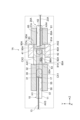
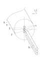
- FIG. 1 is a cross-sectional view taken along the optical axis direction of an optical connection structure according to an embodiment.
- FIG. 2 is a schematic diagram showing the structure of an optical fiber assembly.
- FIG. 3 is a diagram showing an end face of an optical fiber.
- FIG. 4 is a schematic diagram for explaining the configuration of the optical connection structure.
- FIG. 5 is a schematic diagram for explaining the configuration of the optical connection structure.
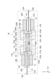
- FIG. 6 is a cross-sectional view taken along the optical axis direction of an optical connection structure according to a modified example of this embodiment.
- FIG. 7 is a cross-sectional view taken along the optical axis direction of an optical connection structure according to a modified example of this embodiment.
- FIG. 8 is a schematic diagram showing the structure of an optical fiber assembly in a modified example of this embodiment.
- FIGS. 9A to 9C are schematic diagrams for explaining reflected light at a lens.
- 10A to 10D are schematic diagrams showing lenses included in an optical connection structure according to a modified example of this embodiment.
- FIG. 11 is a cross-sectional view of an optical fiber of an optical connection structure in a modified example of this embodiment.
- the return light may cause various problems. For example, the return light may destabilize the operation of an amplifier or laser arranged upstream of the optical connection structure, degrading their performance. If return light occurs, the signal quality in bidirectional transmission may also deteriorate. As a result, the quality of optical transmission may deteriorate.
- An optical connection structure includes a first optical fiber assembly, a second optical fiber assembly, a first lens, and a second lens.
- the first optical fiber assembly includes at least one first fiber core.
- the first optical fiber assembly has a first end face. At least one first fiber core is exposed from the first end face.
- the second optical fiber assembly includes at least one second fiber core.
- the second optical fiber assembly has a second end face. At least one second fiber core is exposed from the second end face and is optically coupled to the first end face.
- the first lens and the second lens are arranged in order from the first optical fiber assembly to the second optical fiber assembly between the first optical fiber assembly and the second optical fiber assembly.
- an axis passing through the center of gravity of at least one first fiber core is shifted in a direction along a vertical cross section of at least one first fiber core with respect to the optical axis of the first lens.
- the reflected light from the first lens can be prevented from entering the first fiber core.
- the quality of optical transmission is improved.
- the first optical fiber assembly includes a plurality of first fiber cores as the at least one first fiber core, and an axis passing through the center of gravity of the at least one first fiber core at the first end face may be shifted in a direction perpendicular to the direction in which two of the at least one first fiber core are arranged at the first end face with respect to the optical axis of the first lens.
- the quality of optical transmission between a pair of optical fiber assemblies having a plurality of fiber cores is improved.
- the first optical fiber assembly may include a capillary and a multicore fiber.
- the capillary may have at least one hole extending along the longitudinal direction of the first optical fiber assembly.
- the multicore fiber may be provided in the hole.
- the multicore fiber may include a plurality of first fiber cores.
- the first optical fiber assembly may include a capillary and a plurality of single-core fibers.
- the capillary may have a plurality of holes extending along the longitudinal direction of the first optical fiber assembly.
- the plurality of single-core fibers may be provided in each of the plurality of holes.
- Each of the plurality of single-core fibers may include a first fiber core.
- the number of the first fiber cores may be three or more, the three or more first fiber cores may be arranged in a row on the first end face, and the axis passing through the center of gravity of the three or more first fiber cores may be shifted in a direction perpendicular to the arrangement direction of the three or more first fiber cores with respect to the optical axis of the first lens. In this case, the incidence of the reflected light at the first lens into the first fiber cores may be further suppressed.
- an axis passing through the center of gravity of at least one second fiber core at the second end face may be shifted in a direction perpendicular to the direction in which two of the at least one second fiber core are aligned with respect to the optical axis of the second lens.
- the reflected light at the second lens can be prevented from being incident on the second fiber core.
- the quality of bidirectional optical transmission is improved.
- the second optical fiber assembly includes a plurality of second fiber cores as at least one second fiber core
- the focal length of the first lens is "f1”
- the focal length of the second lens is "f2”
- the core pitch of the multiple first fiber cores at the first end face is “P1”
- the core pitch of the multiple second fiber cores at the second end face is “P2”.
- the first end face may be inclined with respect to the vertical cross section. In this case, optical coupling in the first fiber core can be suppressed for the light reflected at the first end face.
- the first lens may have an opposing surface that faces the first end face.
- the opposing surface may be inclined with respect to the optical axis of the first lens. In this case, the reflected light reflected at the opposing surface may be prevented from entering the first fiber core.
- the shape of the arrangement of at least one first fiber core on the first end face as viewed from the optical axis direction of the first lens and the shape of the arrangement of at least one of the plurality of second fiber cores on the second end face as viewed from the optical axis direction of the second lens may be similar to each other. In this case, optical loss between the fiber cores is reduced.
- At least one first fiber core may be enlarged at the first end face. In this case, even if the beam diameter is enlarged by the first and second lenses, leakage of the incident light can be further suppressed, and optical loss in the optical fiber can be further suppressed.
- a method for manufacturing an optical connection structure includes preparing a first optical fiber assembly, a second optical fiber assembly, a first lens, and a second lens, and arranging the first lens and the second lens in order.
- the first optical fiber assembly includes at least one first fiber core.
- the first optical fiber assembly has a first end face from which the at least one first fiber core is exposed.
- the second optical fiber assembly includes at least one second fiber core.
- the second optical fiber assembly has a second end face from which the at least one second fiber core is exposed and optically coupled to the first end face.
- the first lens and the second lens are arranged in order from the first optical fiber assembly to the second optical fiber assembly between the first optical fiber assembly and the second optical fiber assembly. In the first end face, an axis passing through the center of gravity of the at least one first fiber core is shifted from the optical axis of the first lens in a direction along a vertical cross section of the at least one first fiber core.
- the first optical fiber assembly includes a plurality of first fiber cores as the at least one first fiber core, and an axis passing through the center of gravity of at least one first fiber core at the first end face may be shifted in a direction perpendicular to the direction in which two of the at least one first fiber core are aligned at the first end face with respect to the optical axis of the first lens.
- Figure 1 is a cross-sectional view of an optical connection structure according to one embodiment taken along the optical axis direction.
- the optical connection structure 1 includes a pair of optical fiber assemblies 10, 20, a pair of lenses 30, 40, a pair of holders 50, 60, and a sleeve 70.
- the optical connection structure 1 optically couples the pair of optical fiber assemblies 10, 20 to each other via the pair of lenses 30, 40.
- the optical fiber assembly 10 corresponds to a first optical fiber assembly
- the optical fiber assembly 20 corresponds to a second optical fiber assembly.
- the lens 30 corresponds to a first lens
- the lens 40 corresponds to a second lens.
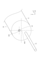
- FIG. 2 is a schematic diagram showing the structure of the optical fiber assembly 10.
- the optical fiber assembly 20 has a structure symmetrical to the optical fiber assembly 10 in the Z-axis direction.
- the X-axis direction, the Y-axis direction, and the Z-axis direction are mutually perpendicular.
- the optical fiber assemblies 10 and 20 each have an elongated shape.
- the optical fiber assemblies 10 and 20 have a cylindrical shape.
- the optical fiber assemblies 10 and 20 extend in the Z-axis direction.
- the optical fiber assembly 10 has an end face 17 facing the lens 30.
- the optical fiber assembly 20 has an end face 27 facing the lens 40.
- the optical fiber assembly 10 includes a capillary 11 and one optical fiber 13.
- the optical fiber assembly 20 includes a capillary 21 and one optical fiber 23.
- the capillary 11 has at least one hole H1.
- the hole H1 passes through the capillary 11 and is connected to an opening formed in the end face 17.
- the hole H1 extends along the longitudinal direction of the optical fiber assembly 10.
- the capillary 21 has at least one hole H2.
- the hole H2 passes through the capillary 21 and is connected to an opening formed in the end face 27.
- the hole H2 extends along the longitudinal direction of the optical fiber assembly 20.
- the capillaries 11 and 21 each have one hole H1 and H2.
- the optical fiber 13 includes at least one fiber core 15 and a cladding 16.
- the optical fiber 13 is provided in the hole H1 and is exposed from the end face 17.
- At least one fiber core 15 is exposed from the end face 17.
- the end face 17 is inclined with respect to a vertical cross section of at least one fiber core 15.
- the "vertical cross section of the fiber core” means a cross section perpendicular to the infinitesimal length direction of the fiber core.
- the "infinite length direction of the fiber core” means the extension direction of the fiber core viewed microscopically.
- the end face 17 is inclined with respect to a vertical cross section of an axis passing through the center of gravity of at least one fiber core 15.
- the end face 17 is inclined with respect to a vertical cross section with respect to the central axis of each fiber core 15.
- the end face 17 is formed by polishing both the optical fiber 13 and the capillary 11.
- the optical fiber 13 is a multi-core fiber including multiple fiber cores 15.
- the axis passing through the center of gravity of at least one fiber core 15 coincides with the central axis of each fiber core 15.
- the fiber core 15 is expanded, for example, at the end face 17 by heating.
- the molded field diameter (MFD) of the fiber core 15 is expanded near the end face 17 by heating, and includes a tapered portion whose diameter increases toward the end face 17.
- the optical fiber 13 is, for example, a TEC (Thermally Expanded Core) fiber, and a shape in which the MFD differs in parts is formed by TEC processing.
- TEC Thermally Expanded Core
- the optical fiber 23 includes at least one fiber core 25.
- the optical fiber 23 is disposed in the hole H2 and is exposed from the end face 27.
- the at least one fiber core 25 is exposed from the end face 27.
- the end face 27 is inclined with respect to a vertical cross section of the at least one fiber core 25.
- the end face 27 is inclined with respect to a vertical cross section of an axis passing through the center of gravity of the at least one fiber core 25.
- the end face 27 is inclined with respect to a vertical cross section of the central axis of each fiber core 25.
- the end face 27 is formed by polishing the optical fiber 23 and the capillary 21 together.
- the optical fiber 23 is a multicore fiber including multiple fiber cores 25.
- At least one fiber core 25 exposed at end face 27 and at least one fiber core 15 exposed at end face 17 are optically coupled to each other.
- each of the multiple fiber cores 25 exposed at end face 27 is optically coupled to a corresponding fiber core 25 among the multiple fiber cores 15 exposed at end face 17.
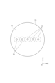
- FIG. 3 is a diagram showing the end face of the optical fiber 13, and shows the end face 17 as viewed from the Z-axis direction.
- the dashed line shows an image of the boundary of the MFD.
- the optical fiber 23 has a similar structure to the optical fiber 13.
- the multiple fiber cores 25 are arranged in a row at the end face 27.
- five fiber cores are arranged in the X-axis direction in the optical fiber 13 and the optical fiber 23.
- the lenses 30 and 40 are arranged between the optical fiber assembly 10 and the optical fiber assembly 20.
- the lens 30 is interposed between the end face 17 of the optical fiber assembly 10 and the lens 40.
- the lens 40 is interposed between the lens 30 and the end face 27 of the optical fiber assembly 20.
- the lenses 30 and 40 are arranged in order from the end face 17 of the optical fiber assembly 10 toward the end face 27 of the optical fiber assembly 20.
- the lens 30, for example, focuses the multiple light beams L emitted from each of the multiple fiber cores 15 of the optical fiber assembly 10 on the opposite side of the optical fiber assembly 10 from the lens 30.
- the lens 40 for example, focuses the light beams L on each fiber core 25 of the end face 27.
- the lenses 30 and 40 are, for example, C lenses.
- the lens 30 is a rod lens having a spherical surface on the lens 40 side, a flat surface on the optical fiber assembly 10 side, and the same outer diameter as the optical fiber assembly 10.
- the lens 40 is a rod lens having a spherical surface on the lens 30 side, a flat surface on the optical fiber assembly 20 side, and the same outer diameter as the optical fiber assembly 20.
- Figures 4 and 5 are schematic diagrams for explaining the configuration of the optical connection structure 1.
- Figures 4 and 5 the relationship between the optical fiber 13, the optical fiber 23, the lens 30, and the lens 40 is shown.
- Figure 4 shows the configuration as viewed from the X-axis direction.
- Figure 5 shows the configuration as viewed from the Y-axis direction.
- Light L1 and light L2 are light L emitted from different fiber cores 15.
- Planes S1, S2, S3, S4, S5, and S6 are shown in Figures 4 and 5.
- Plane S1 corresponds to a virtual plane that includes the intersection of the central axis of the fiber core 15 and the end face 17 and extends in a direction perpendicular to the optical axis CX1 of the lens 30.
- Planes S2 and S3 each include different principal surfaces of the pair of principal surfaces of the lens 30.
- the term "principal surface” means a surface consisting of a set of points where an extension line of an incident light ray at an arbitrary height intersects with an extension line of an exit light ray corresponding to the incident light ray when a light ray parallel to the optical axis of the lens is incident.
- Plane S2 corresponds to the principal surface of the pair of principal surfaces of the lens 30 that faces the optical fiber 13.
- Plane S3 corresponds to the principal surface of the pair of principal surfaces of the lens 30 that faces the lens 40.
- Plane S4 and S5 each include different principal surfaces of the pair of principal surfaces of the lens 40.
- Plane S4 corresponds to the principal surface of the pair of principal surfaces of the lens 40 that faces the lens 30.
- Plane S5 corresponds to the principal surface of the pair of principal surfaces of the lens 40 that faces the optical fiber 23.
- Plane S6 corresponds to a virtual plane that includes the intersection between the central axis of fiber core 25 and the emission surface and extends in a direction perpendicular to optical axis CX2 of lens 40.
- Lens 30 has an opposing surface 31 facing end face 17 and an opposing surface 32 facing lens 40.
- Lens 40 has an opposing surface 41 facing end face 27 and an opposing surface 42 facing lens 30.
- opposing surface 31 is inclined with respect to the optical axis of lens 30, and opposing surface 41 is inclined with respect to the optical axis of lens 40.
- an axis AX1 passing through the center of gravity of at least one fiber core 15 of the optical fiber assembly 10 is offset in a direction along a vertical cross section of at least one fiber core 15 with respect to the optical axis CX1 of the lens 30.
- the axis AX1 is offset in the Y-axis direction with respect to the optical axis CX1 of the lens 30.
- an axis AX2 passing through the center of gravity of at least one fiber core 25 of the optical fiber assembly 20 is offset in a direction along a vertical cross section of at least one fiber core 25 with respect to the optical axis CX2 of the lens 40.
- the axis AX2 is offset in the Y-axis direction with respect to the optical axis CX2 of the lens 40.
- an axis AX1 passing through the center of gravity of at least one fiber core 15 of the optical fiber assembly 10 is offset in a direction along a vertical cross section of at least one fiber core 15 with respect to an axis AX3 passing through the center of gravity of the optical fiber assembly 10.
- an axis AX2 passing through the center of gravity of at least one fiber core 25 is offset in a direction along a vertical cross section of at least one fiber core 35 with respect to an axis AX4 passing through the center of gravity of the optical fiber assembly 20.
- Axis AX1 corresponds to an axis passing through the center of gravity of at least one hole H1 in capillary 11 at end face 17.
- Axis AX3 corresponds to an axis passing through the center of gravity of capillary 11 at end face 17.
- Axis AX2 corresponds to an axis passing through the center of gravity of at least one hole H2 in capillary 21 at end face 27.
- Axis AX4 corresponds to an axis passing through the center of gravity of capillary 21 at end face 27.
- the multiple fiber cores 15 are arranged in a row in the X-axis direction on the end face 17, and the axis AX1 is offset in the Y-axis direction perpendicular to the X-axis direction, which is the arrangement direction of the multiple fiber cores 15, with respect to the optical axis CX1 of the lens 30.
- the axis AX1 passing through the center of gravity of at least one fiber core 15 is offset in a direction perpendicular to the direction in which two of the multiple fiber cores 15 are lined up on the end face 17, with respect to the optical axis CX1 of the lens 30.
- the arrangement direction of the multiple fiber cores 15 is adjusted by the rotation of the optical fiber 13 when the optical fiber 13 is inserted into the hole H1 of the capillary 11.
- the multiple fiber cores 25 are arranged in a row in the X-axis direction on the end face 27, and the axis AX2 is offset in the Y-direction perpendicular to the X-axis direction, which is the arrangement direction of the multiple fiber cores 25, with respect to the optical axis CX2 of the lens 40.
- an axis AX2 passing through the center of gravity of at least one fiber core 25 is shifted with respect to the optical axis CX2 of the lens 40 in a direction perpendicular to the direction in which two of the multiple fiber cores 25 are aligned at the end face 27.
- the arrangement direction of the multiple fiber cores 25 is adjusted by rotating the optical fiber 23 when the optical fiber 23 is inserted into the hole H2 of the capillary 21.
- the optical connection structure 1 includes one fiber core 15 and one fiber core 25, and is configured such that the distance between planes S2 and S1 is equal to the focal length, and the distance between planes S3 and S4 is equal to the sum of the focal length of lens 30 and the focal length of lens 40.
- the fiber core 15 and the fiber core 25 can be optically coupled with relatively low loss.
- the fiber core 15 and the fiber core 25 can be optically coupled with a loss of less than 1 dB.
- the optical connection structure 1 includes multiple fiber cores 15 and multiple fiber cores 25, and that the optical connection structure 1 is configured so that the following formula (1) holds.
- the MFD formed in fiber core 15 is “D 1 ".
- the MFD formed in fiber core 25 is “D 2 ".
- the core pitch of fiber core 15 at end face 17 is “P 1 ".
- the core pitch of fiber core 25 at end face 27 is “P 2 ".
- the focal length of lens 30 is “f 1 ".
- the focal length of lens 40 is “f 2 ".
- core pitch corresponds to the distance between the centers of fiber cores in the XY plane.
- the shape of the arrangement of the multiple fiber cores 15 on the end face 17 as viewed from the direction of the optical axis CX1 of the lens 30 and the shape of the arrangement of the multiple fiber cores 25 on the end face 27 as viewed from the direction of the optical axis of the lens 40 are similar to each other.
- the light distribution formed on the end face 17 of the optical fiber 13 and the light distribution formed on the end face 27 of the optical fiber 23 are similar to each other according to the ratio of the focal lengths f1, f2 of the lens 30 and the lens 40.
- the ratio of the MFD of the fiber core 15 on the end face 17 to the MFD of the fiber core 25 on the end face 27 matches the ratio of the focal lengths f1, f2 of the lens 30 and the lens 40.
- the fiber core 15 and the fiber core 25 can be optically coupled with a relatively low loss.
- the fiber core 15 and the fiber core 25 can be optically coupled with a loss of less than 1 dB.
- the optical connection structure 1 is configured so that the following relationship expressions (2) and (3) are satisfied.
- the holder 50 holds the optical fiber assembly 10 and the lens 30.
- the holder 50 is cylindrical.
- the holder 50 has an inner peripheral surface 51 and an outer peripheral surface 52.
- the inner peripheral surface 51 forms a through hole 55 that penetrates the holder 50 in the extension direction of the holder 50.
- a part of the optical fiber assembly 10 and a part of the lens 30 are accommodated in the through hole 55.
- the holder 50 holds the optical fiber assembly 10 and the lens 30 on the inner peripheral surface 51 that forms the through hole 55.
- the holder 50 fixes the capillary 11 and the lens 30 on the inner peripheral surface 51.
- the lens 30 and the optical fiber assembly 10 are fixed by the holder 50 so that the axis AX1 passing through the center of gravity of the fiber core 15 and the optical axis CX1 of the lens 30 are positioned parallel to each other.
- the end face 17 of the optical fiber assembly 10 and the opposing face 31 of the lens 30 are positioned close to each other.
- the light emitted from the end face 17 of the optical fiber assembly 10 becomes parallel light via the lens 30.
- a collimator is formed by the optical fiber assembly 10 and the lens 30.
- the holder 50 is a collimator holder.
- the holder 60 holds the optical fiber assembly 20 and the lens 40.
- the holder 60 is cylindrical.
- the holder 60 has an inner peripheral surface 61 and an outer peripheral surface 62.
- the inner peripheral surface 61 forms a through hole 65 that penetrates the holder 60 in the extension direction of the holder 60. A part of the optical fiber assembly 20 and a part of the lens 40 are accommodated in the through hole 65.
- the holder 60 holds the optical fiber assembly 20 and the lens 40 on the inner peripheral surface 61 that forms the through hole 65.
- the holder 60 fixes the capillary 21 and the lens 40 on the inner peripheral surface 61.
- the lens 40 and the optical fiber assembly 20 are fixed by the holder 60 so that the axis AX2 passing through the center of gravity of the fiber core 25 and the optical axis CX2 of the lens 40 are positioned parallel to each other.
- the end face 27 of the optical fiber assembly 20 and the opposing face 41 of the lens 40 are positioned close to each other.
- the light emitted from the end face 27 of the optical fiber assembly 20 becomes parallel light via the lens 40.
- a collimator is formed by the optical fiber assembly 20 and the lens 40.
- the holder 60 is a collimator holder.
- the sleeve 70 holds the holder 50 and the holder 60.
- the sleeve 70 is cylindrical.
- the sleeve 70 has an inner circumferential surface 71.
- the inner circumferential surface 71 forms a through hole 75 that passes through the sleeve 70 in the extension direction of the sleeve 70.
- a part of the holder 50 and a part of the holder 60 are accommodated in the through hole 75.
- the sleeve 70 holds the holder 50 and the holder 60 at the inner circumferential surface 71 that forms the through hole 75.
- the sleeve 70 fixes the holder 50 and the holder 60 so that the optical axis CX1 of the lens 30 and the optical axis CX2 of the lens 40 are positioned parallel to each other.
- the amount of deviation in the Y-axis direction of the axis passing through the center of gravity of the multiple fiber cores 15 at the end face 17 relative to the optical axis CX1 of the lens 30 corresponds to the amount of deviation in the Y-axis direction of the axis passing through the center of gravity of the multiple holes H1 at the end face 17 relative to the axis passing through the center of gravity of the capillary 11.
- the amount of deviation in the Y-axis direction of the axis passing through the center of gravity of the multiple fiber cores 15 at the end face 17 relative to the optical axis CX1 of the lens 30 corresponds to the amount of deviation in the Y-axis direction of the axis passing through the center of gravity of the multiple holes H1 at the end face 17 relative to the axis passing through the center of gravity of the capillary 11. Therefore, when fixing the holder 50 and the holder 60 to the sleeve 70, no special method is required to adjust the amount of deviation, and the amount of deviation can be set by a known method that simply adjusts the positional relationship between the holder 50 and the holder 60.
- the optical fiber assembly 10 the optical fiber assembly 20, the lens 30, and the lens 40 are prepared.
- at least one fiber core 15 may be expanded by heating at the end face 17, if necessary.
- the fiber core 15 may be expanded by, for example, TEC processing.
- the optical fiber assembly 10 and the lens 30 are placed in the through hole 55 of the holder 50.
- the optical fiber assembly 10 and the lens 30 are fixed to the inner surface 51 by an adhesive.
- the optical fiber assembly 20 and the lens 40 are placed in the through hole 65 of the holder 60.
- the optical fiber assembly 20 and the lens 40 are fixed to the inner surface 61 by an adhesive.
- holder 50 and holder 60 are placed in through hole 75 of sleeve 70.
- outer peripheral surface 52 of holder 50 and outer peripheral surface 62 of holder 60 are fixed to inner peripheral surface 71 by adhesive.
- holder 50 and holder 60 are fixed to sleeve 70, they are aligned so that fiber core 15 and fiber core 25 are optically coupled with relatively low loss.
- holder 50, holder 60, and sleeve 70 are all housed and sealed in a cylindrical housing.
- the lenses 30 and 40 are arranged between the optical fiber assembly 10 and the optical fiber assembly 20, in order from the optical fiber assembly 10 toward the optical fiber assembly 20.
- the axis AX1 passing through the center of gravity of at least one fiber core 15 at the end face 17 is positioned offset from the optical axis CX1 of the lens 30.
- the axis AX2 passing through the center of gravity of at least one fiber core 25 at the end face 27 is positioned offset from the optical axis CX2 of the lens 40.
- FIG. 6 is a cross-sectional view along the optical axis direction of the optical connection structure in this modified example.
- This modified example is generally similar to or the same as the embodiment described above.
- This modified example differs from the embodiment described above in terms of the configuration for fixing the lens and the optical fiber assembly, the configuration of the optical fiber assembly, and the type of lens. Below, the differences between the embodiment described above and the modified example will be mainly described.
- the optical connection structure 1A optically couples a multicore fiber and a fiber array.
- the optical connection structure 1A includes a pair of optical fiber assemblies 10, 20A, a pair of lenses 30, 40A, a pair of holders 50, 60A, 80A, and a sleeve 90A.
- the optical connection structure 1 optically couples the pair of optical fiber assemblies 10, 20A to each other via the pair of lenses 30, 40A.
- the optical fiber assembly 10 corresponds to a first optical fiber assembly
- the optical fiber assembly 20A corresponds to a second optical fiber assembly.
- the lens 30 corresponds to a first lens
- the lens 40A corresponds to a second lens.
- the optical fiber assembly 20A includes a capillary 21A and a plurality of optical fibers 23A.
- the optical fiber assembly 20A is a fiber array including a plurality of optical fibers 23A.
- the optical fiber assembly 20A has an end face 27A facing the lens 40A.
- the plurality of optical fibers 23A are arranged in an example on the end face 27A.
- the end face 27A is inclined with respect to the optical axis CX2 of the lens 40A.
- the end face 27A is inclined with respect to a perpendicular cross section with respect to the central axis of the fiber core 25.
- Each optical fiber 23A is a single-core fiber including one fiber core 25.
- the capillary 21A has a plurality of holes H2.
- the plurality of holes H2 may be separated from each other or may be connected in the X-axis direction.
- the plurality of optical fibers 23A are provided in the corresponding holes H2 and are exposed from the end face 27A.
- the plurality of fiber cores 25 are exposed from the end face 27A.
- an axis AX2 passing through the center of gravity of the plurality of fiber cores 25 is offset from an axis AX4 passing through the center of gravity of the optical fiber assembly 20A.
- the end face 27A and the end face 17 are optically coupled to each other.
- the multiple fiber cores 25 exposed at the end face 27A and the multiple fiber cores 15 exposed at the end face 17 are optically coupled to each other.
- the multiple fiber cores 25 of the optical fiber assembly 20A are expanded, for example, by heating at the end face 27A.
- the MFD of the fiber cores 25 of the optical fiber assembly 20A is expanded near the end face 27A by heating, and includes a tapered portion whose diameter increases toward the end face 27A.
- the optical fiber 23A is, for example, a TEC fiber, and a shape with a partially different MFD is formed by TEC processing.
- the above-mentioned tapered portion may be formed by TEC processing.
- Lens 30 and lens 40A are arranged between optical fiber assembly 10 and optical fiber assembly 20A.
- Lens 40A is interposed between lens 30 and end face 27A of optical fiber assembly 20.
- Lens 30 and lens 40A are arranged in order from end face 17 of optical fiber assembly 10 toward end face 27A of optical fiber assembly 20A.
- Lens 40A is, for example, a plano-convex lens.
- lens 40A has a convex surface on the lens 30 side and a flat surface on the optical fiber assembly 20A side.
- the holder 60A holds the optical fiber assembly 20A.
- the holder 60A is cylindrical.
- the holder 60A has an inner surface 61.
- a portion of the optical fiber assembly 20A is housed in a through hole 65.
- the holder 60A holds the optical fiber assembly 20A at the inner surface 61 that forms the through hole 65.
- the holder 60A fixes the capillary 21A at the inner surface 61.
- the holder 80A holds the lens 40A.
- the holder 80A is cylindrical.
- the holder 80A has an inner peripheral surface 81A and an outer peripheral surface 82A.
- the inner peripheral surface 81A forms a through hole 85 that penetrates the holder 80A in the extension direction of the holder 80A.
- the lens 40A is accommodated in the through hole 85A.
- the holder 80A holds the lens 40A on the inner peripheral surface 81A that forms the through hole 85A.
- the holder 80A fixes the lens 40A on the inner peripheral surface 81A.
- the through hole 85A of the holder 80A and the through hole 55 of the holder 50A are connected to the side surface 83A of the holder 80A and the side surface 53 of the holder 50A.
- the side surface 83A of the holder 80A and the side surface 53 of the holder 50A are connected to each other so that the optical axis CX1 of the lens 30 and the optical axis CX2 of the lens 40 are positioned parallel to each other.
- Side 83A and side 53 each have a circular ring shape.
- the sleeve 90A holds the holder 60A and the holder 80A.
- the sleeve 90A is cylindrical.
- the sleeve 90A has an inner circumferential surface 91A and a side surface 93A.
- the inner circumferential surface 91A forms a through hole 95A that penetrates the sleeve 90A in the extension direction of the sleeve 90A.
- the side surface 93A is annular. A portion of the holder 80A is accommodated in the through hole 95A.
- the sleeve 90A holds the holder 80A at the inner circumferential surface 91A that forms the through hole 95A.
- the through hole 95A of the sleeve 90A and the through hole 85A of the holder 80A are connected within the through hole 95A.
- the through hole 95A of the sleeve 90A and the through hole 65 of the holder 60A are connected at the side surface 93A of the sleeve 90A and the side surface 63 of the holder 60A.
- the side 93A of the sleeve 90A and the side 63 of the holder 60A are connected to each other so that the optical axis CX2 of the lens 40A and the axis AX2 passing through the center of gravity of the multiple fiber cores 25 are positioned parallel to each other.
- the optical fiber assembly 10 the optical fiber assembly 20A, the lens 30, and the lens 40A are prepared.
- the fiber core 25 is expanded at the end surface 27A by heating.
- the fiber core 25 is expanded, for example, by TEC processing.
- the optical fiber assembly 10 and the lens 30 are placed in the through hole 55 of the holder 50.
- the optical fiber assembly 10 and the lens 30 are fixed to the inner surface 51 by an adhesive.
- the optical fiber assembly 20A is placed in the through hole 65 of the holder 60A.
- the optical fiber assembly 20A is fixed to the inner surface 61 by an adhesive.
- the lens 40A is placed in the through hole 85A of the holder 80A.
- the lens 40A is fixed to the inner surface 81A by an adhesive.
- the holder 80A is placed in the through hole 95A of the sleeve 90A.
- the fiber core 15 and the fiber core 25 are aligned and fixed so as to be optically coupled with relatively low loss.
- the sleeve 90A and the holder 80A are fixed to each other, the sleeve 90A and the holder 60A are fixed to each other, and the holder 50 and the holder 80A are fixed to each other. These are fixed, for example, with an adhesive.
- the axis AX1 passing through the center of gravity of the multiple fiber cores 15 of the optical fiber 13 is offset from the optical axis CX1 of the lens 30, the axis passing through the center of gravity of the multiple holes H1 of the capillary 11 is offset from the axis passing through the center of gravity of the capillary 11.
- the arrangement of the multiple fiber cores 15 is adjusted by rotating the optical fiber 13. Due to the above-mentioned alignment and the rotation of the optical fiber 13, the axis passing through the center of gravity of the capillary 21A including the multiple fiber cores 25 is offset from the optical axis CX2 of the lens 40A in a direction perpendicular to the arrangement direction of the multiple optical fibers 23A.
- Figure 7 is a cross-sectional view along the optical axis direction of the optical connection structure in this modified example.
- This modified example is generally similar to or the same as the embodiment described above.
- This modified example differs from the embodiment described above in terms of the configuration for fixing the lens and the optical fiber assembly, the configuration of the optical fiber assembly, and the type of lens. Below, the differences between the embodiment described above and the modified example will be mainly described.
- the optical connection structure 1B optically couples a pair of fiber arrays together.
- the optical connection structure 1B includes a pair of optical fiber assemblies 10B, 20B, a pair of lenses 30B, 40A, a pair of holders 50B, 60B, 160B, and a pair of sleeves 170B, 180B.
- the optical connection structure 1B optically couples the pair of optical fiber assemblies 10B, 20B together via the pair of lenses 30B, 40A.
- the optical fiber assembly 10B corresponds to a first optical fiber assembly
- the optical fiber assembly 20B corresponds to a second optical fiber assembly.
- the optical fiber assemblies 10B and 20B each have an elongated shape.
- the optical fiber assemblies 10B and 20B each have a cylindrical shape.
- the optical fiber assemblies 10B and 20B each extend in the Z-axis direction.
- the optical fiber assembly 10B includes a capillary 11B and a plurality of optical fibers 13B.
- the optical fiber assembly 10B is a fiber array including a plurality of optical fibers 13B.
- the optical fiber assembly 10B has an end face 17B facing the lens 30B.
- the plurality of optical fibers 13B are arranged in an example on the end face 17B.
- the end face 17B is inclined with respect to the optical axis CX1 of the lens 30B.
- the end face 17B is inclined with respect to a vertical cross section perpendicular to the central axis of the plurality of fiber cores 25.
- Each optical fiber 13B is a single-core fiber including one fiber core 15.
- the capillary 11B has multiple holes H1.
- the multiple holes H1 may be separated from each other or may be connected in the X-axis direction.
- the multiple optical fibers 13B are provided in the corresponding holes H1 and are exposed from the end face 17B.
- the multiple fiber cores 15 are exposed from the end face 17B.
- the fiber cores 15 are expanded by heating at the end face 17B.
- the fiber cores 15 are expanded near the end face 17B by heating, and include a tapered portion whose diameter increases toward the end face 17B.
- the optical fiber assembly 20B includes a capillary 21B and a plurality of optical fibers 23B.
- the optical fiber assembly 20B is a fiber array including a plurality of optical fibers 23B.
- the optical fiber assembly 20B has an end face 27B facing the lens 40B.
- the plurality of optical fibers 23B are arranged in an example on the end face 27B.
- the end face 27B is inclined with respect to the optical axis CX2 of the lens 40B.
- the end face 27B is inclined with respect to a vertical cross section perpendicular to the central axis of the plurality of fiber cores 25.
- Each of the optical fibers 23B includes one fiber core 25.
- the capillary 21B has a plurality of holes H2.
- the holes H2 may be spaced apart from one another or may be connected in the X-axis direction.
- the optical fibers 23B are provided in the corresponding holes H2 and are exposed from the end surface 27B.
- the fiber cores 25 are exposed from the end surface 27B.
- End face 27B and end face 17B are optically coupled to each other.
- the multiple fiber cores 25 exposed at end face 27B and the multiple fiber cores 15 exposed at end face 17B are optically coupled to each other.
- Capillary 11B has multiple holes H1. Each of the multiple holes H1 is connected to multiple openings formed in end face 17B. Each of the multiple holes H1 extends along the longitudinal direction of optical fiber assembly 10B. In end face 17B, axis AX2 passing through the center of gravity of the multiple holes H1 is offset from optical axis CX1 of lens 30B.
- Capillary 21B has multiple holes H2.
- the multiple holes H2 are connected to an opening formed in end face 27B.
- Each of the multiple holes H2 extends along the longitudinal direction of optical fiber assembly 20B.
- axis AX4 passing through the center of gravity of the multiple holes H2 is offset from optical axis CX2 of lens 40A.
- axis AX1 passing through the center of gravity of the multiple fiber cores 15 coincides with axis AX3 passing through the center of gravity of optical fiber assembly 10B.
- axis AX2 passing through the center of gravity of the multiple fiber cores 25 coincides with axis AX4 passing through the center of gravity of optical fiber assembly 20B.
- Lens 30B and lens 40A are arranged between optical fiber assembly 10B and optical fiber assembly 20B.
- Lens 30B is interposed between lens 40A and end face 17B of optical fiber assembly 10B.
- Lenses 30B and lens 40A are arranged in order from end face 17B of optical fiber assembly 10B toward end face 27B of optical fiber assembly 20B.
- Lens 30B is, for example, a plano-convex lens.
- lens 30B has a convex surface on the lens 40A side and a flat surface on the optical fiber assembly 10B side.
- Holder 160B holds lens 30B and lens 40A.
- Holder 160B is cylindrical.
- Holder 160B has an inner circumferential surface 161B and an outer circumferential surface 162B.
- Inner circumferential surface 161B forms a through hole 165B that penetrates holder 160B in the extension direction of holder 160B.
- Lenses 30B and 40A are housed in through hole 165B.
- Holder 160B holds lens 30B and lens 40A on inner circumferential surface 161B that forms through hole 165B.
- Holder 160B fixes lens 30B and lens 40A on inner circumferential surface 161B.
- the sleeve 170B holds the holder 160B.
- the sleeve 170B is cylindrical.
- the sleeve 170B has an inner circumferential surface 171B and a side surface 173B.
- the inner circumferential surface 171B forms a through hole 175B that passes through the sleeve 170B in the extension direction of the sleeve 170B.
- a portion of the holder 160B is accommodated in the through hole 175B.
- the sleeve 170B holds the holder 160B at the inner circumferential surface 171B that forms the through hole 175B.
- the sleeve 170B fixes the holder 160B at the inner circumferential surface 171B.
- Through hole 175B of sleeve 170B and through hole 55 of holder 50B are connected at side 173B of sleeve 170B and side 53 of holder 50B.
- Side 173B of sleeve 170B and side 53 of holder 50B are connected to each other so that optical axis CX1 of lens 30B and axis AX3 of optical fiber assembly 10B are positioned parallel to each other.
- Side 173B and side 53 each have a circular ring shape.
- Sleeve 180B holds holder 160B.
- Sleeve 180B is cylindrical.
- Sleeve 180B has an inner circumferential surface 181B and a side surface 183B.
- Inner circumferential surface 181B forms a through hole 185B that passes through sleeve 180B in the extension direction of sleeve 180B.
- a portion of sleeve 180B is accommodated in through hole 185B.
- Sleeve 180B holds holder 160B at inner circumferential surface 181B that forms through hole 185B.
- Sleeve 180B fixes holder 160B at inner circumferential surface 181B.
- Through hole 185B of sleeve 180B and through hole 65 of holder 60B are connected at side 183B of sleeve 180B and side 63 of holder 60B.
- Side 183B of sleeve 180B and side 63 of holder 60B are connected to each other so that optical axis CX2 of lens 40B and axis AX4 of optical fiber assembly 20B are positioned parallel to each other.
- Side 183B and side 63 each have a circular ring shape.
- the optical fiber assembly 10B, the optical fiber assembly 20B, the lens 30B, and the lens 40A are prepared.
- the fiber core 15 is expanded at the end face 17B by heating.
- the fiber core 15 is expanded, for example, by TEC processing.
- optical fiber assembly 10B is placed in through hole 55 of holder 50B.
- optical fiber assembly 10B and lens 30B are fixed to inner surface 51 by adhesive.
- Optical fiber assembly 20B is placed in through hole 65 of holder 60B.
- optical fiber assembly 20B is fixed to inner surface 61 by adhesive.
- Lens 30B and lens 40A are placed in through hole 165B of holder 160B.
- lens 30B and lens 40A are fixed to inner surface 161B by adhesive.
- the fiber cores 15 and 25 are aligned so as to be optically coupled with relatively low loss.
- holder 160B, sleeve 170B, and sleeve 180B are fixed to each other, sleeve 170B and holder 50B are fixed to each other, and sleeve 180B and holder 60B are fixed to each other.
- the arrangement of the multiple fiber cores 15 is adjusted by rotating the optical fiber 13B. Alignment is performed so that the axis passing through the center of gravity of the capillary 11B containing the multiple fiber cores 15 is shifted in a direction perpendicular to the arrangement direction of the multiple optical fibers 23B with respect to the optical axis CX2 of the lens 30B, and the axis passing through the center of gravity of the capillary 21B containing the multiple fiber cores 25 is shifted in a direction perpendicular to the arrangement direction of the multiple optical fibers 23B with respect to the optical axis CX2 of the lens 40B.
- the above-mentioned amount of shift is precisely adjusted. As a result, the effect of return light on each optical fiber 13B and optical fiber 23B is easily suppressed.
- the reflected light L R at the lens 230 is shown as an example.
- the lens 230 is a plano-convex lens.
- Fig. 9(a) shows a state in which a part of the light emitted from the fiber core 15 is reflected by the rear end surface 231 of the lens 230 and the reflected light L R returns to the fiber core 15.
- Fig. 9(b) shows a state in which a part of the light emitted from the fiber core 15 is reflected by the front end surface 232 of the lens 230 and the reflected light L R returns to the fiber core 15.
- the reflected light L R at the lens 230 enters the original fiber core 15 and the adjacent fiber core 15, and a part of the light is combined within the fiber core 15.
- the reflected light L R entering the same fiber core 15 may destabilize the operation of the equipment arranged upstream.
- the reflected light L R entering the different fiber core 15 becomes noise in the originally propagating optical signal. As a result, there is a risk of degrading the signal quality.
- the axis AX1 passing through the center of gravity of the fiber core 15 is parallel to the optical axis CX1 of the lens 230 and is shifted from the optical axis CX1 in a direction perpendicular to the arrangement direction of the fiber cores 15.
- the reflection direction at the front end surface 232 of the lens 230 is different from that in the configurations shown in Fig. 9(a) and Fig. 9(b).
- the reflected light L R at the front end surface 232 of the lens 230 is warped from each fiber core 15, and the incidence of the reflected light L R on each fiber core 15 is suppressed. Therefore, the reflected light is coupled to the fiber core 15 from which it is emitted or the adjacent fiber core 15, thereby reducing the effects of operational instability and signal quality degradation.
- an axis AX1 passing through the center of gravity of at least one fiber core 15 is shifted in a direction along a vertical cross section of at least one fiber core 15 with respect to an optical axis CX1 of the lens 30.
- the reflected light L 1 R reflected by the lens 30 can be suppressed from being incident on the fiber core 15.
- the quality of optical transmission is improved.
- the same effect is achieved in the optical connection structures 1A and 1B.
- the optical fiber assembly 10 includes multiple fiber cores 15 as at least one fiber core 14.
- an axis AX1 passing through the center of gravity of at least one fiber core 15 at the end face 17 may be shifted with respect to the optical axis CX1 of the lens 30 in a direction perpendicular to the direction in which two of the at least one fiber core 15 are arranged at the end face 17.
- the quality of optical transmission is improved between the optical fiber assembly 10 having multiple fiber cores 15 and the optical fiber assembly 20 having multiple fiber cores 25.
- the same effect is achieved in the optical connection structures 1A and 1B.
- the optical fiber assembly 10 may include a capillary 11 and a multi-core fiber.
- the capillary 11 has at least one hole H1.
- the hole H1 extends along the longitudinal direction of the optical fiber assembly 10.
- the multi-core fiber may be provided in the hole H1.
- the axis AX1 passing through the center of gravity of the fiber core 15 can be easily realized with respect to the optical axis CX1 of the lens 30, and reliability can also be improved.
- the optical connection structure 1A also has the same effect.
- the optical fiber assembly 10B may include a capillary 11B and a plurality of single-core fibers.
- the capillary 11B may have a plurality of holes H1 extending along the longitudinal direction of the optical fiber assembly 10B.
- the plurality of single-core fibers may be provided in each of the plurality of holes H1.
- Each of the plurality of single-core fibers may include a fiber core 15.
- the axis AX1 passing through the center of gravity of the fiber core 15 can be easily realized with respect to the optical axis CX1 of the lens 30, and reliability can also be improved.
- the same effect is achieved in the optical fiber assembly 20A of the optical connection structure 1A.
- the multiple fiber cores 15 may be arranged in a row on the end surface 17 in a direction perpendicular to the direction in which the axis AX1 passing through the center of gravity of at least one fiber core 15 is shifted from the optical axis CX1 of the lens 30.
- the reflected light at the lens 30 can be further suppressed from entering the fiber core 15.
- the optical connection structures 1A and 1B also have the same effect.
- the end face 17 may be inclined with respect to a cross section perpendicular to the central axis of at least one fiber core 15. In this case, optical coupling in the fiber core 15 for the light reflected at the end face 17 can be suppressed. The same effect is achieved in the optical connection structures 1A and 1B.
- the reflectance at the end face 17 for the same wavelength can be reduced to -65 dB even without an anti-reflection coating (AR coating).
- AR coating anti-reflection coating
- the same fiber is polished 4 times, the reduction in reflectance is limited to -35 dB, but if an AR coating with a reflectance of 0.25% is further vapor-deposited, the reflectance can be reduced to -61 dB.
- the lens 30 has an opposing surface 31 that faces the end face 17.
- the opposing surface 31 may be inclined with respect to the optical axis CX1 of the lens 30. In this case, the reflected light reflected at the opposing surface 31 can be prevented from entering the fiber core 15.
- the optical connection structure 1A also has the same effect.
- the axis AX2 passing through the center of gravity of at least one fiber core 25 at the end face 27 may be shifted with respect to the optical axis CX2 of the lens 40 in a vertical cross section perpendicular to the direction in which two of the at least one fiber core 25 are aligned.
- the reflected light at the lens 40 can be prevented from being incident on the fiber core 25.
- the quality of bidirectional optical transmission is improved.
- the same effect is achieved in the optical connection structures 1A and 1B.
- the shape of the arrangement of at least one fiber core 15 on the end face 17 of the lens 30 as viewed from the optical axis direction may be similar to the shape of the arrangement of at least one fiber core 25 on the end face 27 of the lens 40 as viewed from the optical axis direction. In this case, optical loss between the fiber cores is reduced. The same effect is achieved in the optical connection structures 1A and 1B.
- the focal length of lens 30 is "f1"
- the focal length of lens 40 is "f2”
- the core pitch of the multiple fiber cores 15 at end face 17 is “P1”
- the core pitch of the multiple fiber cores 25 at end face 27 is “P2”.
- leakage of incident light can be further suppressed, and optical loss in the optical fiber can be further suppressed.
- optical connection structures 1A and 1B can be achieved.
- At least one fiber core 15 may be enlarged at the end face 17. In this case, even if the beam diameter is enlarged by the lenses 30 and 40, the leakage of the incident light can be further suppressed, and the optical loss of the optical fiber can be further suppressed. The same effect can be achieved in the optical connection structures 1A and 1B.
- the present invention is not limited to the above embodiments and can be applied to various embodiments.
- the configurations of the optical connection structures 1, 1A, and 1B may be combined.
- the configuration of the fiber bundle side and the configuration of the MCF side may have different configurations from those of the examples shown by the optical connection structures 1, 1A, and 1B.
- the multiple lenses arranged between the optical fiber assembly 10 and the optical fiber assembly 20 may include a type of lens other than the C lens used in the optical connection structures 1 and 1A and the convex lens used in the optical connection structures 1A and 1B.
- the various lenses shown in Figures 10(a) to 10(d) may be used.
- Figures 10(a) to 10(d) show various lenses 30D, 30E, 30F, and 30G and the light L incident on each lens 30D, 30E, 30F, and 30G.
- lens 30D is a biconvex lens and includes a pair of end faces 31D, 32D that are convex. For example, end faces 31D, 32D are aspheric.
- Lens 30D is made of a single material.
- lens 30E is an achromatic lens and is formed by bonding together multiple plates. Each of the multiple plates of lens 30E has a curved surface and is made of a different material. For example, end faces 31E, 32E are aspheric.
- lens 30F is a ball lens. Lens 30F is made of a sphere made of a single material.
- lens 30G is a GRIN lens. Lens 30G includes a pair of end faces 31G, 32G that are flat. Lens 30G is made of a cylinder with different refractive index distributions in the radial direction.
- the optical connection structure 1 may have a structure in which multiple types of lenses are combined.
- the optical connection structure 1 may have a configuration in which two or more lenses selected from a biconvex lens, an achromatic lens, a ball lens, a C lens, a GRIN lens, etc. are combined.
- the lenses located at both ends correspond to a first lens and a second lens, respectively.
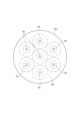
- FIG. 11 shows a cross-sectional view of optical fiber 13J as a modified example.
- Optical fiber 13J differs from optical fiber 13 only in the number and arrangement of fiber cores 15.
- Seven fiber cores 15 are provided in optical fiber 13J.
- the seven fiber cores 15 have a close-packed structure in the XY plane so as to function optically.
- the parts described as being fixed with adhesive may also be fixed by welding.
- Optical connection structure 10B 1, 1A, 1B...
- Optical connection structure 10B 20, 20A, 20B...
Landscapes
- Physics & Mathematics (AREA)
- General Physics & Mathematics (AREA)
- Optics & Photonics (AREA)
- Optical Couplings Of Light Guides (AREA)
Abstract
光接続構造体1において、第1レンズと第2レンズとが、第1光ファイバアセンブリと第2光ファイバアセンブリとの間において、第1光ファイバアセンブリから第2光ファイバアセンブリに向かって順に配列されている。第1端面において、少なくとも1つの第1ファイバコアの重心を通る軸が、第1レンズの光軸に対して、少なくとも1つの第1ファイバコアの垂直断面方向にずれている。
Description
本開示は、光接続構造体、及び、光接続構造体の製造方法に関するものである。本出願は、2023年7月4日に出願された日本出願の特願2023-109871に基づく優先権を主張し、前記日本出願に記載された全ての記載内容を援用する。
一対の光ファイバアセンブリを光結合する光接続構造体が知られている。光ファイバアセンブリは、光ファイバを含んでいる。例えば、特許文献1及び特許文献2は、一対の光ファイバアセンブリの間に一対のレンズを配列した光接続構造体が開示されている。一対の光ファイバアセンブリは、一対のレンズによって光結合されている。
本開示の一側面に係る光接続構造体は、第1光ファイバアセンブリと、第2光ファイバアセンブリと、第1レンズ及び第2レンズと、を備えている。第1光ファイバアセンブリは、少なくとも1つの第1ファイバコアを含んでいる。第1光ファイバアセンブリは、第1端面を有している。第1端面は、少なくとも1つの第1ファイバコアが露出している。第2光ファイバアセンブリは、少なくとも1つの第2ファイバコアを含んでいる。第2光ファイバアセンブリは、第2端面を有している。第2端面は、少なくとも1つの第2ファイバコアが露出していると共に第1端面と光結合する。第1レンズと第2レンズとは、第1光ファイバアセンブリと第2光ファイバアセンブリとの間において、第1光ファイバアセンブリから第2光ファイバアセンブリに向かって順に配列されている。第1端面において、少なくとも1つの第1ファイバコアの重心を通る軸が、第1レンズの光軸に対して、少なくとも1つの第1ファイバコアの垂直断面に沿った方向にずれている。
[本開示が解決しようとする課題]
上述した光接続構造体においてレンズが用いられる場合、レンズの端面において反射された光の一部が戻り光として光ファイバの端面に入射するおそれがある。戻り光は、様々な不具合を引き起こすおそれがある。例えば、戻り光は、光接続構造体の上流に配置された増幅器又はレーザの動作を不安定にし、それらの性能を劣化させる。戻り光が生じれば、双方向伝送において信号品質も劣化する。この結果、光伝送の品質が劣化するおそれがある。
[本開示の効果]
上述した光接続構造体においてレンズが用いられる場合、レンズの端面において反射された光の一部が戻り光として光ファイバの端面に入射するおそれがある。戻り光は、様々な不具合を引き起こすおそれがある。例えば、戻り光は、光接続構造体の上流に配置された増幅器又はレーザの動作を不安定にし、それらの性能を劣化させる。戻り光が生じれば、双方向伝送において信号品質も劣化する。この結果、光伝送の品質が劣化するおそれがある。
[本開示の効果]
本開示によれば、一対の光ファイバアセンブリを用いた光伝送の品質を向上する光接続構造体、及び、光接続構造体の製造方法を提供することができる。
[本開示の実施形態の説明]
[本開示の実施形態の説明]
最初に本開示の実施形態を列記して説明する。
(1)本開示の実施形態に係る光接続構造体は、第1光ファイバアセンブリと、第2光ファイバアセンブリと、第1レンズ及び第2レンズと、を備えている。第1光ファイバアセンブリは、少なくとも1つの第1ファイバコアを含んでいる。第1光ファイバアセンブリは、第1端面を有している。第1端面は、少なくとも1つの第1ファイバコアが露出している。第2光ファイバアセンブリは、少なくとも1つの第2ファイバコアを含んでいる。第2光ファイバアセンブリは、第2端面を有している。第2端面は、少なくとも1つの第2ファイバコアが露出していると共に第1端面と光結合する。第1レンズと第2レンズとは、第1光ファイバアセンブリと第2光ファイバアセンブリとの間において、第1光ファイバアセンブリから第2光ファイバアセンブリに向かって順に配列されている。第1端面において、少なくとも1つの第1ファイバコアの重心を通る軸が、第1レンズの光軸に対して少なくとも1つの第1ファイバコアの垂直断面に沿った方向にずれている。
この場合、第1レンズにおける反射光について、第1ファイバコアへの入射が抑制され得る。この結果、光伝送の品質が向上する。
(2)上記(1)の光接続構造体において、第1光ファイバアセンブリは、少なくとも1つの第1ファイバコアとして、複数の第1ファイバコアを含んでおり、第1端面において、少なくとも1つの第1ファイバコアの重心を通る軸が、第1レンズの光軸に対して、第一端面において少なくとも1つの第1ファイバコアのうちの2つが並ぶ方向に対して直交する方向にずれていてもよい。この場合、複数のファイバコアを有する一対の光ファイバアセンブリ間の光伝送の品質が向上する。
(3)上記(2)の光接続構造体において、第1光ファイバアセンブリは、キャピラリと、マルチコアファイバとを含んでいてもよい。キャピラリは、第1光ファイバアセンブリの長尺方向に沿って延在する少なくとも1つの孔を有していてもよい。マルチコアファイバは、上記孔に設けられていてもよい。マルチコアファイバは、複数の第1ファイバコアを含んでいてもよい。この場合、マルチコアファイバがキャピラリによって位置決めされるため、第1レンズの光軸に対して、第1ファイバコアの重心を通る軸がずれた構成が容易に実現されると共に信頼性も向上し得る。
(4)上記(2)の光接続構造体において、第1光ファイバアセンブリは、キャピラリと、複数のシングルコアファイバとを含んでいてもよい。キャピラリは、当該第1光ファイバアセンブリの長尺方向に沿って延在する複数の孔を有していてもよい。複数のシングルコアファイバは、複数の孔のそれぞれに設けられていてもよい。複数のシングルコアファイバの各々は、第1ファイバコアを含んでいてもよい。この場合、複数のシングルコアファイバがキャピラリによって位置決めされるため、第1レンズの光軸に対して、第1ファイバコアの重心を通る軸がずれた構成が容易に実現されると共に信頼性も向上し得る。
(5)上記(2)から(4)のいずれか一つの光接続構造体において、複数の第1ファイバコアは3つ以上あって、第1端面において、3つ以上の第1ファイバコアは一列に配列されており、上記3つ以上の第1ファイバコアの重心を通る軸は、第1レンズの光軸に対して上記3つ以上の第1ファイバコアの配列方向と直交する方向にずれていてもよい。この場合、第1レンズにおける反射光について、第1ファイバコアへの入射がさらに抑制され得る。
(6)上記(2)から(5)のいずれか一つの光接続構造体において、第2端面において、少なくとも1つの第2ファイバコアの重心を通る軸が、第2レンズの光軸に対して、少なくとも1つの第2ファイバコアのうちの2つが並ぶ方向に対して直交する方向にずれていてもよい。この場合、第2レンズにおける反射光について、第2ファイバコアへの入射が抑制され得る。この結果、双方向光伝送の品質が向上する。
(7)上記(2)から(6)のいずれか一つの光接続構造体において、第2光ファイバアセンブリは、少なくとも1つの第2ファイバコアとして、複数の第2ファイバコアを含んでおり、
(P2/P1)×0.9 ≦ f2/f1 ≦ (P2/P1)×1.1
なる関係が満たされていてもよい。第1レンズの焦点距離が“f1”であり、第2レンズの焦点距離が“f2”であり、第1端面における複数の第1ファイバコアのコアピッチが“P1”であり、第2端面における複数の第2ファイバコアのコアピッチが“P2”である。この場合、入射光の漏れがさらに抑制され、光ファイバの光損失がさらに抑制され得る。
(8)上記(1)から(7)のいずれか一つの光接続構造体において、第1端面は、垂直断面に対して傾斜していてもよい。この場合、第1端面において反射した反射光について、第1ファイバコアにおける光結合が抑制され得る。
(9)上記(1)から(8)のいずれか一つの光接続構造体において、第1レンズは、第1端面と対向する対向面を有していてもよい。対向面は、第1レンズの光軸に対して傾斜していてもよい。この場合、対向面において反射した反射光について、第1ファイバコアへの入射が抑制され得る。
(10)上記(1)から(9)のいずれか一つの光接続構造体において、第1レンズの光軸方向から見た第1端面における少なくとも1つの第1ファイバコアの配列の形状と、第2レンズの光軸方向から見た第2端面における少なくとも1つの複数の第2ファイバコアの配列の形状とは、互いに相似形であってもよい。この場合、ファイバコア間において光損失が低減される。
(11)上記(1)から(10)のいずれか一つの光接続構造体において、少なくとも1つの第1ファイバコアは、第1端面において拡大されていてもよい。この場合、第1及び第2レンズによって、ビーム径が拡大されても、入射光の漏れがさらに抑制され、光ファイバの光損失がさらに抑制され得る。
(12)本開示の実施形態に係る光接続構造体の製造方法は、第1光ファイバアセンブリと、第2光ファイバアセンブリと、第1レンズ及び第2レンズとを準備することと、第1レンズと第2レンズとが順に配列されることと、を有している。第1光ファイバアセンブリは、少なくとも1つの第1ファイバコアを含んでいる。第1光ファイバアセンブリは、少なくとも1つの第1ファイバコアが露出している第1端面を有している。第2光ファイバアセンブリは、少なくとも1つの第2ファイバコアを含んでいる。第2光ファイバアセンブリは、少なくとも1つの第2ファイバコアが露出していると共に第1端面と光結合する第2端面を有している。第1レンズ及び第2レンズは、第1光ファイバアセンブリと第2光ファイバアセンブリとの間において、第1光ファイバアセンブリから第2光ファイバアセンブリに向かって順に配列される。第1端面において、少なくとも1つの第1ファイバコアの重心を通る軸が、第1レンズの光軸に対して、少なくとも1つの第1ファイバコアの垂直断面に沿った方向にずらして配置される。
(13)上記(12)の光接続構造体の製造方法は、第1光ファイバアセンブリは、少なくとも1つの第1ファイバコアとして複数の第1ファイバコアを含んでおり、第1端面において、少なくとも1つの第1ファイバコアの重心を通る軸を、第1レンズの光軸に対して、第1端面における少なくとも1つの第1ファイバコアのうちの2つが並ぶ方向に対して直交する方向にずらしてもよい。
(14)上記(12)または(13)の光接続構造体の製造方法は、第1光ファイバアセンブリの準備において、少なくとも1つの第1ファイバコアが、第1端面において、加熱よって拡大される。この場合、第1及び第2レンズによって、ビーム径が拡大されても、入射光の漏れがさらに抑制され、光ファイバの光損失がさらに抑制され得る。
[本開示の実施形態の詳細]
[本開示の実施形態の詳細]
本開示の実施形態の具体例を、以下に図面を参照しつつ説明する。本発明はこれらの例示に限定されるものではなく、請求の範囲によって示され、請求の範囲と均等の意味及び範囲内でのすべての変更が含まれることが意図される。図面の説明においては同一要素には同一符号を付し、重複する説明を省略する。
まず、図1から図5を参照して、本実施形態における光接続構造体の一例を説明する。図1は、一実施形態における光接続構造体の光軸方向に沿った断面図である。
光接続構造体1は、一対の光ファイバアセンブリ10,20と、一対のレンズ30,40と、一対のホルダー50,60と、スリーブ70とを備えている。光接続構造体1は、一対のレンズ30,40を介して、一対の光ファイバアセンブリ10,20を互いに光結合する。例えば、光ファイバアセンブリ10は第1光ファイバアセンブリに相当し、光ファイバアセンブリ20は第2光ファイバアセンブリに相当する。例えば、レンズ30は第1レンズに相当し、レンズ40は第2レンズに相当する。
図2は、光ファイバアセンブリ10の構造を示す概略図である。本実施形態に示す例において、光ファイバアセンブリ20は、光ファイバアセンブリ10とZ軸方向において、対称な構造を有している。本明細書において、X軸方向、Y軸方向、及び、Z軸方向は、互いに直交している。光ファイバアセンブリ10,20は、それぞれ長尺形状を呈している。本実施形態に示す例において、光ファイバアセンブリ10,20は、円柱形状を呈している。光ファイバアセンブリ10,20は、Z軸方向に延在している。
光ファイバアセンブリ10は、レンズ30に対向する端面17を有している。光ファイバアセンブリ20は、レンズ40に対向する端面27を有している。本実施形態に示す例において、光ファイバアセンブリ10は、キャピラリ11と1つの光ファイバ13とを含んでいる。光ファイバアセンブリ20は、キャピラリ21と1つの光ファイバ23とを含んでいる。
図2に示されているように、キャピラリ11は、少なくとも1つの孔H1を有している。孔H1は、キャピラリ11を貫通しており、端面17において形成された開口に連通している。孔H1は、光ファイバアセンブリ10の長尺方向に沿って延在している。キャピラリ21は、少なくとも1つの孔H2を有している。孔H2は、キャピラリ21を貫通しており、端面27において形成された開口に連通している。孔H2は、光ファイバアセンブリ20の長尺方向に沿って延在している。本実施形態に示す例において、キャピラリ11,21は、それぞれ、1つの孔H1,H2を有している。
光ファイバ13は、少なくとも1つのファイバコア15とクラッド16とを含んでいる。光ファイバ13は、孔H1に設けられており、端面17から露出している。少なくとも1つのファイバコア15は、端面17から露出している。端面17は、少なくとも1つのファイバコア15の垂直断面に対して傾斜している。本明細書において、「ファイバコアの垂直断面」とは、ファイバコアの微小長さ方向に垂直な断面を意味している。「ファイバコアの微小長さ方向」とは、微視的に見たファイバコアの延在方向を意味する。端面17は、少なくとも1つのファイバコア15の重心を通る軸の垂直断面に対して傾斜している。端面17は、各ファイバコア15の中心軸に対する垂直断面に対して傾斜している。例えば、端面17は、光ファイバ13とキャピラリ11とが共に研磨されることによって形成される。本実施形態に示す例において、光ファイバ13は、複数のファイバコア15を含んでいるマルチコアファイバである。本実施形態に示す例において、少なくとも1つのファイバコア15の重心を通る軸と各ファイバコア15の中心軸とは、一致している。
ファイバコア15は、例えば、端面17において加熱によって拡大されている。ファイバコア15のモールドフィールド直径(MFD)は、加熱によって端面17付近において拡大されており、端面17に向かうに従って径が大きくなるテーパ形状部を含んでいる。光ファイバ13は、例えば、TEC(Thermally Expanded Core)ファイバであり、TEC処理によってMFDが部分的に異なる形状が形成されている。例えば、TEC処理によって、上述したテーパ形状部が形成されていてもよい。
光ファイバ23は、少なくとも1つのファイバコア25を含んでいる。光ファイバ23は、孔H2に設けられており、端面27から露出している。少なくとも1つのファイバコア25は、端面27から露出している。端面27は、少なくとも1つのファイバコア25の垂直断面に対して傾斜している。端面27は、少なくとも1つのファイバコア25の重心を通る軸の垂直断面に対して傾斜している。端面27は、各ファイバコア25の中心軸に対する垂直断面に対して傾斜している。例えば、端面27は、光ファイバ23とキャピラリ21とが共に研磨されることによって形成される。本実施形態に示す例において、光ファイバ23は、複数のファイバコア25を含んでいるマルチコアファイバである。
端面27において露出している少なくとも1つのファイバコア25と、端面17において露出している少なくとも1つのファイバコア15とが、互いに光結合している。本実施形態に示されている例において、端面27において露出している複数のファイバコア25の各々が、端面17において露出している複数のファイバコア15のうち対応するファイバコア25に光結合されている。
本実施形態に示す例において、図3に示されているように、複数のファイバコア15は、端面17においてX軸方向に一列に配列されている。図3は、光ファイバ13の端面を表す図であり、端面17をZ軸方向から見た図である。図3において、破線はMFDの境界部のイメージを示している。本実施形態に示す例において、光ファイバ23は、光ファイバ13と同様な構造を有している。複数のファイバコア25は、端面27において一列に配列されている。本実施形態に示す例において、光ファイバ13及び光ファイバ23において、5つのファイバコアがX軸方向に配列されている。
レンズ30及びレンズ40は、光ファイバアセンブリ10と光ファイバアセンブリ20との間において配列されている。レンズ30は、光ファイバアセンブリ10の端面17とレンズ40との間に介在している。レンズ40は、レンズ30と光ファイバアセンブリ20の端面27との間に介在している。レンズ30及びレンズ40は、光ファイバアセンブリ10の端面17から光ファイバアセンブリ20の端面27に向かって順に配列されている。
レンズ30は、例えば、光ファイバアセンブリ10の複数のファイバコア15のそれぞれから出射した複数の光Lをレンズ30に対して光ファイバアセンブリ10の反対側に集光する。レンズ40は、例えば、端面27の各ファイバコア25に光Lを集光する。レンズ30及びレンズ40は、例えば、Cレンズである。例えば、レンズ30は、レンズ40側に球面を有し、光ファイバアセンブリ10側に平面を有し、光ファイバアセンブリ10と同一の外径を有するロッドレンズである。例えば、レンズ40は、レンズ30側に球面を有し、光ファイバアセンブリ20側に平面を有し、光ファイバアセンブリ20と同一の外径を有するロッドレンズである。
図4及び図5を参照して、レンズ30及びレンズ40が有する特性の一例を説明する。図4及び図5は、光接続構造体1の構成を説明するための概略図である。図4及び図5において、光ファイバ13、光ファイバ23、レンズ30、及びレンズ40の関係が示されている。図4は、X軸方向から見た構成を示している。図5は、Y軸方向から見た構成を示している。光L1と光L2とは、互いに異なるファイバコア15から出射された光Lである。図4及び図5において、平面S1,S2,S3,S4,S5,S6が示されている。
平面S1は、ファイバコア15の中心軸と端面17の交点を含むと共にレンズ30の光軸CX1と直交する方向に延在する仮想面に相当する。平面S2及び平面S3は、それぞれ、レンズ30の一対の主面のうち互いに異なる主面を含んでいる。本明細書において、「主面」は、レンズの光軸に平行な光線を入射した場合に、任意の高さの入射光の光線の延長線と、当該入射光の光線に対応する出射光の光線の延長線とが互いに交わる点の集合からなる面を意味する。平面S2は、レンズ30の一対の主面のうち、光ファイバ13側の主面に相当する。平面S3は、レンズ30の一対の主面のうち、レンズ40側の主面に相当する。平面S4及び平面S5は、それぞれ、レンズ40の一対の主面のうち互いに異なる主面を含んでいる。平面S4は、レンズ40の一対の主面のうち、レンズ30側の主面に相当する。平面S5は、レンズ40の一対の主面のうち、光ファイバ23側の主面に相当する。平面S6は、ファイバコア25の中心軸と出射面との交点を含むと共にレンズ40の光軸CX2と直交する方向に延在する仮想面に相当する。
レンズ30は、端面17と対向する対向面31と、レンズ40と対向する対向面32とを有している。レンズ40は、端面27と対向する対向面41と、レンズ30と対向する対向面42とを有している。図1に示されている例では、対向面31がレンズ30の光軸に対して傾斜しており、対向面41がレンズ40の光軸に対して傾斜している。
光ファイバアセンブリ10の端面17において、光ファイバアセンブリ10の少なくとも1つのファイバコア15の重心を通る軸AX1が、レンズ30の光軸CX1に対して、少なくとも1つのファイバコア15の垂直断面に沿った方向にずれている。換言すれば、端面17において、軸AX1が、レンズ30の光軸CX1に対して、Y軸方向にずれている。光ファイバアセンブリ20の端面27において、光ファイバアセンブリ20の少なくとも1つのファイバコア25の重心を通る軸AX2が、レンズ40の光軸CX2に対して、少なくとも1つのファイバコア25の垂直断面に沿った方向にずれている。端面27において、軸AX2が、レンズ40の光軸CX2に対して、Y軸方向にずれている。
本実施形態に示す例において、図2に示されているように、光ファイバアセンブリ10の端面17において、光ファイバアセンブリ10の少なくとも1つのファイバコア15の重心を通る軸AX1は、光ファイバアセンブリ10の重心を通る軸AX3に対して、少なくとも1つのファイバコア15の垂直断面に沿った方向にずれている。同様に、端面27において、少なくとも1つのファイバコア25の重心を通る軸AX2は、光ファイバアセンブリ20の重心を通る軸AX4に対して、少なくとも1つのファイバコア35の垂直断面に沿った方向にずれている。
軸AX1は、端面17においてキャピラリ11において少なくとも1つの孔H1の重心を通る軸に相当する。軸AX3は、端面17においてキャピラリ11の重心を通る軸に相当する。軸AX2は、端面27においてキャピラリ21において少なくとも1つの孔H2の重心を通る軸に相当する。軸AX4は、端面27においてキャピラリ21の重心を通る軸に相当する。
本実施形態に示す例において、複数のファイバコア15は、端面17において、X軸方向に一列に配列されており、軸AX1は、レンズ30の光軸CX1に対して、複数のファイバコア15の配列方向であるX軸方向と直交するY軸方向にずれている。端面17において、少なくとも1つのファイバコア15の重心を通る軸AX1が、レンズ30の光軸CX1に対して、端面17において複数のファイバコア15のうちの2つが並ぶ方向に対して直交する方向にずれている。複数のファイバコア15の配列方向は、キャピラリ11の孔H1に光ファイバ13が挿入される際に、光ファイバ13の回転によって調整される。同様に、複数のファイバコア25は、端面27において、X軸方向に一列に配列されており、軸AX2は、レンズ40の光軸CX2に対して、複数のファイバコア25の配列方向であるX軸方向と直交するY方向にずれている。端面27において、少なくとも1つのファイバコア25の重心を通る軸AX2が、レンズ40の光軸CX2に対して、端面27において複数のファイバコア25のうちの2つが並ぶ方向に対して直交する方向にずれている。複数のファイバコア25の配列方向は、キャピラリ21の孔H2に光ファイバ23が挿入される際に、光ファイバ23の回転によって調整される。
例えば、仮に、光接続構造体1が1つのファイバコア15と1つのファイバコア25とを含んでおり、光接続構造体1が、平面S2と平面S1との距離が焦点距離に等しく、かつ、平面S3と平面S4との距離がレンズ30の焦点距離とレンズ40の焦点距離との和に等しくなるように構成されることを想定する。この場合、ファイバコア15とファイバコア25とが比較的低損失で光結合され得る。例えば、ファイバコア15とファイバコア25とが1dB未満の損失で光結合され得る。
次に、光接続構造体1が複数のファイバコア15と複数のファイバコア25とを含んでおり、光接続構造体1が、以下の式(1)が成り立つように構成されることを想定する。
D1/D2=P1/P2=f1/f2 ・・・(1)
ファイバコア15において形成されるMFDが“D1”である。ファイバコア25において形成されるMFDが“D2”である。端面17におけるファイバコア15のコアピッチが“P1”である。端面27におけるファイバコア25のコアピッチが“P2”である。レンズ30の焦点距離が“f1”である。レンズ40の焦点距離が“f2”である。本明細書において、「コアピッチ」とは、XY平面におけるファイバコアの中心間の距離に相当する。
この場合、レンズ30の光軸CX1の方向から見た端面17における複数のファイバコア15の配列の形状と、レンズ40の光軸方向から見た端面27における複数のファイバコア25の配列の形状とは、互いに相似形である。光ファイバ13の端面17で形成される光分布と、光ファイバ23の端面27で形成される光分布とは、レンズ30及びレンズ40の焦点距離f1,f2の比率に応じた相似形となる。端面17におけるファイバコア15のMFDと、端面27におけるファイバコア25のMFDとの比率は、レンズ30及びレンズ40の焦点距離f1,f2の比率に一致する。この場合も、ファイバコア15とファイバコア25とが比較的低損失で光結合され得る。例えば、ファイバコア15とファイバコア25とが1dB未満の損失で光結合され得る。
本実施形態に示す例において、光接続構造体1は、以下の関係式(2)及び(3)が満たされるように構成される。
(P2/P1)×0.9 ≦ f2/f1 ≦ (P2/P1)×1.1 ・・・(2)
(P2/P1)×0.9 ≦ D2/D1 ≦ (P2/P1)×1.1 ・・・(3)
ホルダー50は、光ファイバアセンブリ10とレンズ30とを保持している。ホルダー50は、筒状を呈している。ホルダー50は、内周面51と外周面52とを有している。内周面51は、ホルダー50の延在方向にホルダー50を貫通する貫通孔55を形成している。光ファイバアセンブリ10の一部及びレンズ30の一部は、貫通孔55に収容されている。ホルダー50は、貫通孔55を形成する内周面51において、光ファイバアセンブリ10とレンズ30とを保持している。ホルダー50は、内周面51において、キャピラリ11とレンズ30とを固定している。ホルダー50によって、ファイバコア15の重心を通る軸AX1とレンズ30の光軸CX1とが平行に位置するように、レンズ30と光ファイバアセンブリ10とが固定されている。
これによって、光ファイバアセンブリ10の端面17とレンズ30の対向面31と近接して配置される。光ファイバアセンブリ10の端面17から出射光は、レンズ30を介して、平行光となる。すなわち、光ファイバアセンブリ10とレンズ30によって、コリメータが形成されている。ホルダー50は、コリメータホルダである。
ホルダー60は、光ファイバアセンブリ20とレンズ40とを保持している。ホルダー60は、筒状を呈している。ホルダー60は、内周面61と外周面62とを有している。内周面61は、ホルダー60の延在方向にホルダー60を貫通する貫通孔65を形成している。光ファイバアセンブリ20の一部及びレンズ40の一部は、貫通孔65に収容されている。ホルダー60は、貫通孔65を形成する内周面61において、光ファイバアセンブリ20とレンズ40とを保持している。ホルダー60は、内周面61において、キャピラリ21とレンズ40とを固定している。ホルダー60によって、ファイバコア25の重心を通る軸AX2とレンズ40の光軸CX2とが平行に位置するように、レンズ40と光ファイバアセンブリ20とが固定されている。
これによって、光ファイバアセンブリ20の端面27とレンズ40の対向面41と近接して配置される。光ファイバアセンブリ20の端面27から出射光は、レンズ40を介して、平行光となる。すなわち、光ファイバアセンブリ20とレンズ40によって、コリメータが形成されている。ホルダー60は、コリメータホルダである。
スリーブ70は、ホルダー50とホルダー60とを保持している。スリーブ70は、筒状を呈している。スリーブ70は、内周面71を有している。内周面71は、スリーブ70の延在方向にスリーブ70を貫通する貫通孔75を形成している。ホルダー50の一部とホルダー60の一部とは、貫通孔75に収容されている。スリーブ70は、貫通孔75を形成する内周面71において、ホルダー50とホルダー60とを保持している。スリーブ70によって、レンズ30の光軸CX1とレンズ40の光軸CX2とが平行に位置するように、ホルダー50とホルダー60とが固定されている。
本実施形態に示される例において、端面17において複数のファイバコア15の重心を通る軸がレンズ30の光軸CX1に対してY軸方向にずれたずれ量は、端面17において、複数の孔H1の重心を通る軸がキャピラリ11の重心を通る軸に対してY軸方向にずれたずれ量に相当する。上記ずれ量は、端面17において複数のファイバコア15の重心を通る軸がレンズ30の光軸CX1に対してずれたY軸方向成分のずれ量は、端面17において、複数の孔H1の重心を通る軸がキャピラリ11の重心を通る軸に対してずれたY軸方向成分のずれ量に相当する。したがって、スリーブ70に対するホルダー50及びホルダー60の固定において、上記ずれ量を調整する特殊な手法は必要なく、ホルダー50とホルダー60との位置関係を調整するだけの既知の手法によって上記ずれ量が設定され得る。
次に、光接続構造体1の製造方法の一例を示す。まず、光ファイバアセンブリ10と光ファイバアセンブリ20とレンズ30とレンズ40とが準備される。光ファイバアセンブリ10の準備において、必要に応じ、少なくとも1つのファイバコア15が、端面17において、加熱よって拡大されてもよい。ファイバコア15は、例えば、TEC処理によって拡大処理されてもよい。
次に、ホルダー50の貫通孔55に、光ファイバアセンブリ10とレンズ30とが配置される。例えば、光ファイバアセンブリ10とレンズ30とは、接着剤によって内周面51に固定される。ホルダー60の貫通孔65に、光ファイバアセンブリ20とレンズ40とが配置される。例えば、光ファイバアセンブリ20とレンズ40とは、接着剤によって内周面61に固定される。
次に、スリーブ70の貫通孔75に、ホルダー50とホルダー60とが配置される。例えば、ホルダー50の外周面52とホルダー60の外周面62とが、接着剤によって内周面71に固定される。スリーブ70にホルダー50とホルダー60とが固定される際、ファイバコア15とファイバコア25とが比較的低損失で光結合されるように、調心される。次に、例えば、ホルダー50とホルダー60とスリーブ70とは、全体が円筒状のハウジングに収容されて封止される。
以上によって、レンズ30とレンズ40とが、光ファイバアセンブリ10と光ファイバアセンブリ20との間において、光ファイバアセンブリ10から光ファイバアセンブリ20に向かって順に配列される。端面17において少なくとも1つのファイバコア15の重心を通る軸AX1は、レンズ30の光軸CX1に対してずらして配置される。端面27において少なくとも1つのファイバコア25の重心を通る軸AX2は、レンズ40の光軸CX2に対してずらして配置される。
次に、図6を参照して、本実施形態の変形例における光接続構造体について説明する。図6は、本変形例における光接続構造体の光軸方向に沿った断面図である。本変形例は、概ね、上述した実施形態と類似又は同じである。本変形例は、レンズと光ファイバアセンブリとを固定する構成、光ファイバアセンブリの構成、及び、レンズの種別に関して、上述した実施形態と相違する。以下、上述した実施形態と変形例との相違点を主として説明する。
光接続構造体1Aは、マルチコアファイバとファイバアレイとを光結合する。光接続構造体1Aは、一対の光ファイバアセンブリ10,20Aと、一対のレンズ30,40Aと、一対のホルダー50,60A,80Aと、スリーブ90Aとを備えている。光接続構造体1は、一対のレンズ30,40Aを介して、一対の光ファイバアセンブリ10,20Aを互いに光結合する。例えば、光ファイバアセンブリ10は第1光ファイバアセンブリに相当し、光ファイバアセンブリ20Aは第2光ファイバアセンブリに相当する。例えば、レンズ30は第1レンズに相当し、レンズ40Aは第2レンズに相当する。
光ファイバアセンブリ20Aは、キャピラリ21Aと複数の光ファイバ23Aとを含んでいる。光ファイバアセンブリ20Aは、複数の光ファイバ23Aを含んでいるファイバアレイである。光ファイバアセンブリ20Aは、レンズ40Aに対向する端面27Aを有している。複数の光ファイバ23Aは、端面27Aにおいて一例に配列されている。端面27Aは、レンズ40Aの光軸CX2に対して傾斜している。端面27Aは、ファイバコア25の中心軸に対する垂直断面に対して傾斜している。
各光ファイバ23Aは、それぞれ1つのファイバコア25を含んでいるシングルコアファイバである。キャピラリ21Aは、複数の孔H2を有している。複数の孔H2は、互いに離隔していてもよいし、X軸方向において連結されていてもよい。複数の光ファイバ23Aは、それぞれ対応する孔H2に設けられており、端面27Aから露出している。複数のファイバコア25は、端面27Aから露出している。端面27Aにおいて、複数のファイバコア25の重心を通る軸AX2は、光ファイバアセンブリ20Aの重心を通る軸AX4に対してずれている。
端面27Aと端面17とは、互いに光結合している。換言すれば、端面27Aにおいて露出している複数のファイバコア25と、端面17において露出している複数のファイバコア15とが、互いに光結合している。光ファイバアセンブリ20Aの複数のファイバコア25は、例えば、端面27Aにおいて加熱によって拡大されている。光ファイバアセンブリ20Aのファイバコア25のMFDは、加熱によって端面27A付近において拡大されており、端面27Aに向かうに従って径が大きくなるテーパ形状部を含んでいる。光ファイバ23Aは、例えば、TECファイバであり、TEC処理によってMFDが部分的に異なる形状が形成されている。例えば、TEC処理によって、上述したテーパ形状部が形成されていてもよい。
レンズ30及びレンズ40Aは、光ファイバアセンブリ10と光ファイバアセンブリ20Aとの間において配列されている。レンズ40Aは、レンズ30と光ファイバアセンブリ20の端面27Aとの間に介在している。レンズ30及びレンズ40Aは、光ファイバアセンブリ10の端面17から光ファイバアセンブリ20Aの端面27Aに向かって順に配列されている。レンズ40Aは、例えば、平凸レンズである。例えば、レンズ40Aは、レンズ30側に凸面を有し、光ファイバアセンブリ20A側に平面を有している。
ホルダー60Aは、光ファイバアセンブリ20Aを保持している。ホルダー60Aは、筒状を呈している。ホルダー60Aは、内周面61を有している。光ファイバアセンブリ20Aの一部は、貫通孔65に収容されている。ホルダー60Aは、貫通孔65を形成する内周面61において、光ファイバアセンブリ20Aを保持している。ホルダー60Aは、内周面61において、キャピラリ21Aを固定している。
ホルダー80Aは、レンズ40Aを保持している。ホルダー80Aは、筒状を呈している。ホルダー80Aは、内周面81Aと外周面82Aとを有している。内周面81Aは、ホルダー80Aの延在方向にホルダー80Aを貫通する貫通孔85を形成している。レンズ40Aは、貫通孔85Aに収容されている。ホルダー80Aは、貫通孔85Aを形成する内周面81Aにおいて、レンズ40Aを保持している。ホルダー80Aは、内周面81Aにおいて、レンズ40Aを固定している。ホルダー80Aの貫通孔85Aとホルダー50Aの貫通孔55とは、ホルダー80Aの側面83Aとホルダー50Aの側面53とにおいて連通している。ホルダー80Aの側面83Aとホルダー50Aの側面53とは、レンズ30の光軸CX1とレンズ40の光軸CX2とが平行に位置するように、互いに接続されている。側面83Aと側面53は、それぞれ、円環状を呈している。
スリーブ90Aは、ホルダー60Aとホルダー80Aとを保持している。スリーブ90Aは、筒状を呈している。スリーブ90Aは、内周面91Aと側面93Aとを有している。内周面91Aは、スリーブ90Aの延在方向にスリーブ90Aを貫通する貫通孔95Aを形成している。側面93Aは、円環状を呈している。ホルダー80Aの一部は、貫通孔95Aに収容されている。スリーブ90Aは、貫通孔95Aを形成する内周面91Aにおいて、ホルダー80Aを保持している。スリーブ90Aの貫通孔95Aとホルダー80Aの貫通孔85Aとは、貫通孔95A内において連通している。スリーブ90Aの貫通孔95Aとホルダー60Aの貫通孔65とは、スリーブ90Aの側面93Aとホルダー60Aの側面63とにおいて連通している。スリーブ90Aの側面93Aとホルダー60Aの側面63とは、レンズ40Aの光軸CX2と複数のファイバコア25の重心を通る軸AX2とが平行に位置するように、互いに接続されている。
次に、光接続構造体1Aの製造方法の一例を示す。まず、光ファイバアセンブリ10と光ファイバアセンブリ20Aとレンズ30とレンズ40Aとが準備される。光ファイバアセンブリ20Aの準備において、例えば、ファイバコア25が、端面27Aにおいて、加熱よって拡大される。ファイバコア25は、例えば、TEC処理によって拡大される。
次に、ホルダー50の貫通孔55に、光ファイバアセンブリ10とレンズ30とが配置される。例えば、光ファイバアセンブリ10とレンズ30とは、接着剤によって内周面51に固定される。ホルダー60Aの貫通孔65に、光ファイバアセンブリ20Aが配置される。例えば、光ファイバアセンブリ20Aは、接着剤によって内周面61に固定される。ホルダー80Aの貫通孔85Aに、レンズ40Aが配置される。例えば、レンズ40Aは、接着剤によって内周面81Aに固定される。
次に、スリーブ90Aの貫通孔95Aに、ホルダー80Aが配置される。次に、スリーブ90Aの側面93Aとホルダー60Aの側面63とが接した状態、かつ、ホルダー50Aの側面53とホルダー80Aの側面83Aとが接した状態で、ファイバコア15とファイバコア25とが比較的低損失で光結合されるように調心して固定される。スリーブ90Aとホルダー80Aとが互いに固定され、スリーブ90Aとホルダー60Aとが互いに固定され、ホルダー50とホルダー80Aとが互いに固定される。これらは、例えば接着剤により固定される。
光ファイバ13の複数のファイバコア15の重心を通る軸AX1はレンズ30の光軸CX1に対してずれているため、キャピラリ11の複数の孔H1の重心を通る軸はキャピラリ11の重心を通る軸からずれている。複数のファイバコア15の配列は、光ファイバ13の回転によって調整されている。上述した調心と光ファイバ13の回転とによって、複数のファイバコア25を含むキャピラリ21Aの重心を通る軸は、レンズ40Aの光軸CX2に対して、複数の光ファイバ23Aの配列方向と直交する方向にずれて位置する。
本変形例では、レンズ30,40A、ホルダー50,60A,80A、及びスリーブ90Aの各々の軸が互いに平行となった状態で、調心が可能である。したがって、軸の傾きに起因する隙間が生じないため、固定において樹脂の充填量が低減される。この結果、信頼性が向上する。
次に、図7及び図8を参照して、本実施形態の変形例における光接続構造体について説明する。図7は、本変形例における光接続構造体の光軸方向に沿った断面図である。本変形例は、概ね、上述した実施形態と類似又は同じである。本変形例は、レンズと光ファイバアセンブリとを固定する構成、光ファイバアセンブリの構成、及び、レンズの種別に関して、上述した実施形態と相違する。以下、上述した実施形態と変形例との相違点を主として説明する。
光接続構造体1Bは、一対のファイバアレイ同士を光結合する。光接続構造体1Bは、一対の光ファイバアセンブリ10B,20Bと、一対のレンズ30B,40Aと、一対のホルダー50B,60B,160Bと、一対のスリーブ170B,180Bと、を備えている。光接続構造体1Bは、一対のレンズ30B,40Aを介して、一対の光ファイバアセンブリ10B,20Bを互いに光結合する。例えば、光ファイバアセンブリ10Bは第1光ファイバアセンブリに相当し、光ファイバアセンブリ20Bは第2光ファイバアセンブリに相当する。
光ファイバアセンブリ10B,20Bは、それぞれ長尺形状を呈している。本変形例において、光ファイバアセンブリ10B,20Bは、円柱形状を呈している。光ファイバアセンブリ10B,20Bは、Z軸方向に延在している。
光ファイバアセンブリ10Bは、キャピラリ11Bと複数の光ファイバ13Bとを含んでいる。光ファイバアセンブリ10Bは、複数の光ファイバ13Bを含んでいるファイバアレイである。光ファイバアセンブリ10Bは、レンズ30Bに対向する端面17Bを有している。複数の光ファイバ13Bは、端面17Bにおいて一例に配列されている。端面17Bは、レンズ30Bの光軸CX1に対して傾斜している。端面17Bは、複数のファイバコア25の中心軸に直交する垂直断面に対して傾斜している。
各光ファイバ13Bは、1つのファイバコア15を含んでいるシングルコアファイバである。キャピラリ11Bは、複数の孔H1を有している。複数の孔H1は、互いに離隔していてもよいし、X軸方向において連結されていてもよい。複数の光ファイバ13Bは、それぞれ対応する孔H1に設けられており、端面17Bから露出している。
複数のファイバコア15は、端面17Bから露出している。例えば、ファイバコア15は、端面17Bにおいて加熱によって拡大されている。ファイバコア15は、加熱によって端面17B付近において拡大されており、端面17Bに向かって径が大きくなるテーパ形状部を含んでいる。
光ファイバアセンブリ20Bは、キャピラリ21Bと複数の光ファイバ23Bとを含んでいる。光ファイバアセンブリ20Bは、複数の光ファイバ23Bを含んでいるファイバアレイである。光ファイバアセンブリ20Bは、レンズ40Bに対向する端面27Bを有している。複数の光ファイバ23Bは、端面27Bにおいて一例に配列されている。端面27Bは、レンズ40Bの光軸CX2に対して傾斜している。端面27Bは、複数のファイバコア25の中心軸に直交する垂直断面に対して傾斜している。
複数の光ファイバ23Bは、それぞれ1つのファイバコア25を含んでいる。キャピラリ21Bは、複数の孔H2を有している。複数の孔H2は、互いに離隔していてもよいし、X軸方向において連結されていてもよい。複数の光ファイバ23Bは、それぞれ対応する孔H2に設けられており、端面27Bから露出している。複数のファイバコア25は、端面27Bから露出している。
端面27Bと端面17Bとは、互いに光結合している。換言すれば、端面27Bにおいて露出している複数のファイバコア25と、端面17Bにおいて露出している複数のファイバコア15とが、互いに光結合している。
キャピラリ11Bは、複数の孔H1を有している。複数の孔H1は、それぞれ、端面17Bにおいて形成された複数の開口に連通している。複数の孔H1は、それぞれ、光ファイバアセンブリ10Bの長尺方向に沿って延在している。端面17Bにおいて、複数の孔H1の重心を通る軸AX2は、レンズ30Bの光軸CX1に対してずれている。
キャピラリ21Bは、複数の孔H2を有している。複数の孔H2は、端面27Bにおいて形成された開口に連通している。複数の孔H2は、それぞれ、光ファイバアセンブリ20Bの長尺方向に沿って延在している。端面27Bにおいて、複数の孔H2の重心を通る軸AX4は、レンズ40Aの光軸CX2に対してずれている。
本変形例において、図8に示されているように、端面17Bにおいて、複数のファイバコア15の重心を通る軸AX1は、光ファイバアセンブリ10Bの重心を通る軸AX3と一致している。端面27Bにおいて、複数のファイバコア25の重心を通る軸AX2は、光ファイバアセンブリ20Bの重心を通る軸AX4と一致している。
レンズ30B及びレンズ40Aは、光ファイバアセンブリ10Bと光ファイバアセンブリ20Bとの間において配列されている。レンズ30Bは、レンズ40Aと光ファイバアセンブリ10Bの端面17Bとの間に介在している。レンズ30B及びレンズ40Aは、光ファイバアセンブリ10Bの端面17Bから光ファイバアセンブリ20Bの端面27Bに向かって順に配列されている。レンズ30Bは、例えば、平凸レンズである。例えば、レンズ30Bは、レンズ40A側に凸面を有し、光ファイバアセンブリ10B側に平面を有している。
ホルダー160Bは、レンズ30Bとレンズ40Aとを保持している。ホルダー160Bは、筒状を呈している。ホルダー160Bは、内周面161Bと外周面162Bとを有している。内周面161Bは、ホルダー160Bの延在方向にホルダー160Bを貫通する貫通孔165Bを形成している。レンズ30Bとレンズ40Aは、貫通孔165Bに収容されている。ホルダー160Bは、貫通孔165Bを形成する内周面161Bにおいて、レンズ30B及びレンズ40Aを保持している。ホルダー160Bは、内周面161Bにおいて、レンズ30B及びレンズ40Aを固定している。
スリーブ170Bは、ホルダー160Bを保持している。スリーブ170Bは、筒状を呈している。スリーブ170Bは、内周面171Bと側面173Bとを有している。内周面171Bは、スリーブ170Bの延在方向にスリーブ170Bを貫通する貫通孔175Bを形成している。ホルダー160Bの一部は、貫通孔175Bに収容されている。スリーブ170Bは、貫通孔175Bを形成する内周面171Bにおいて、ホルダー160Bを保持している。スリーブ170Bは、内周面171Bにおいて、ホルダー160Bを固定している。
スリーブ170Bの貫通孔175Bとホルダー50Bの貫通孔55とは、スリーブ170Bの側面173Bとホルダー50Bの側面53とにおいて連通している。スリーブ170Bの側面173Bとホルダー50Bの側面53とは、レンズ30Bの光軸CX1と光ファイバアセンブリ10Bの軸AX3とが平行に位置するように、互いに接続されている。側面173Bと側面53は、それぞれ、円環状を呈している。
スリーブ180Bは、ホルダー160Bを保持している。スリーブ180Bは、筒状を呈している。スリーブ180Bは、内周面181Bと側面183Bとを有している。内周面181Bは、スリーブ180Bの延在方向にスリーブ180Bを貫通する貫通孔185Bを形成している。スリーブ180Bの一部は、貫通孔185Bに収容されている。スリーブ180Bは、貫通孔185Bを形成する内周面181Bにおいて、ホルダー160Bを保持している。スリーブ180Bは、内周面181Bにおいて、ホルダー160Bを固定している。
スリーブ180Bの貫通孔185Bとホルダー60Bの貫通孔65とは、スリーブ180Bの側面183Bとホルダー60Bの側面63とにおいて連通している。スリーブ180Bの側面183Bとホルダー60Bの側面63とは、レンズ40Bの光軸CX2と光ファイバアセンブリ20Bの軸AX4とが平行に位置するように、互いに接続されている。側面183Bと側面63は、それぞれ、円環状を呈している。
次に、光接続構造体1Bの製造方法の一例を示す。まず、光ファイバアセンブリ10Bと光ファイバアセンブリ20Bとレンズ30Bとレンズ40Aとが準備される。光ファイバアセンブリ10Bの準備において、例えば、ファイバコア15が、端面17Bにおいて、加熱よって拡大される。ファイバコア15は、例えば、TEC処理によって拡大される。
次に、ホルダー50Bの貫通孔55に、光ファイバアセンブリ10Bが配置される。例えば、光ファイバアセンブリ10Bとレンズ30Bとは、接着剤によって内周面51に固定される。ホルダー60Bの貫通孔65に、光ファイバアセンブリ20Bが配置される。例えば、光ファイバアセンブリ20Bは、接着剤によって内周面61に固定される。ホルダー160Bの貫通孔165Bに、レンズ30Bとレンズ40Aが配置される。例えば、レンズ30Bとレンズ40Aは、接着剤によって内周面161Bに固定される。
次に、ホルダー160Bの外周面162Bが内周面171Bと内周面181Bとに接し、スリーブ170Bの側面173Bとホルダー50Bの側面53とが接し、かつ、スリーブ170Bの側面173Bとホルダー50Bの側面53とが接した状態で、ファイバコア15とファイバコア25とが比較的低損失で光結合されるように調心される。調心された状態で、ホルダー160Bとスリーブ170B及びスリーブ180Bとが互いに固定され、スリーブ170Bとホルダー50Bとが互いに固定され、かつ、スリーブ180Bとホルダー60Bとが互いに固定される。
複数のファイバコア15の配列は、光ファイバ13Bの回転によって調整される。複数のファイバコア15を含むキャピラリ11Bの重心を通る軸が、レンズ30Bの光軸CX2に対して、複数の光ファイバ23Bの配列方向と直交する方向にずれ、且つ、複数のファイバコア25を含むキャピラリ21Bの重心を通る軸が、レンズ40Bの光軸CX2に対して、複数の光ファイバ23Bの配列方向と直交する方向にずれるように、調心が実行される。本変形例では、上記ずれ量が精密に調整される。この結果、各光ファイバ13B及び光ファイバ23Bへの戻り光の影響が抑制されやすい。
次に、実施形態に係る光接続構造体から得られる作用効果について説明する。光接続構造体にレンズが用いられる場合、レンズの表面において反射が発生する。図9(a)から図9(c)において、例として、レンズ230における反射光LRが示されている。レンズ230は、平凸レンズである。図9(a)は、ファイバコア15から出射された光の一部がレンズ230の後方端面231で反射された反射光LRがファイバコア15に戻る様子を示している。図9(b)は、ファイバコア15から出射された光の一部がレンズ230の前方端面232で反射された反射光LRがファイバコア15に戻る様子を示している。
レンズ230における反射光LRは、出射した元のファイバコア15及び隣接したファイバコア15に入射し、その一部がファイバコア15内で結合する。同じファイバコア15に入射した反射光LRは、上流に配置された機器の動作を不安定にさせるおそれがある。双方向伝送のように出射元のファイバコア15と隣接するファイバコア15の光の伝搬方向が逆になっている場合は、異なるファイバコア15に入射した反射光LRは元々伝搬している光信号に対して雑音となる。この結果、信号品質を劣化させるおそれがある。
これに対して、図9(c)に示されているように、ファイバコア15の重心を通る軸AX1が、レンズ230の光軸CX1に対して平行であり、かつ、光軸CX1に対してファイバコア15の配列方向と直交する方向にずれている。図9(c)に示されている構成において、レンズ230の前方端面232での反射方向は、図9(a)及び図9(b)に示されている構成の場合と異なる。図9(c)に示されている構成において、レンズ230の前方端面232における反射光LRは、各ファイバコア15から反れ、各ファイバコア15への入射が抑制される。このため、反射光が出射元のファイバコア15又は隣接するファイバコア15への結合することによって、動作不安定及び信号品質劣化の影響が低減され得る。
光接続構造体1において、端面17において、少なくとも1つのファイバコア15の重心を通る軸AX1が、レンズ30の光軸CX1に対して少なくとも1つのファイバコアの15垂直断面に沿った方向にずれている。この場合、レンズ30において反射した反射光LRについて、ファイバコア15への入射が抑制され得る。この結果、光伝送の品質が向上する。光接続構造体1A,1Bにおいても、同様の作用効果が奏される。
光接続構造体1において、光ファイバアセンブリ10は、少なくとも1つのファイバコア14として、複数のファイバコア15を含んでいる。光ファイバアセンブリ10は、端面17において、少なくとも1つのファイバコア15の重心を通る軸AX1が、レンズ30の光軸CX1に対して、端面17において少なくとも1つのファイバコア15のうちの2つが並ぶ方向に対して直交する方向にずれていてもよい。この場合、複数のファイバコア15を有する光ファイバアセンブリ10と、複数のファイバコア25を有する光ファイバアセンブリ20との間において、光伝送の品質が向上する。光接続構造体1A,1Bにおいても、同様の作用効果が奏される。
光接続構造体1において、光ファイバアセンブリ10は、キャピラリ11と、マルチコアファイバとを含んでいてもよい。キャピラリ11は、少なくとも1つの孔H1を有している。孔H1は、光ファイバアセンブリ10の長尺方向に沿って延在している。マルチコアファイバは、上記孔H1に設けられていてもよい。この場合、マルチコアファイバがキャピラリ11,21によって位置決めされるため、レンズ30の光軸CX1に対して、ファイバコア15の重心を通る軸AX1が容易に実現されると共に信頼性も向上し得る。光接続構造体1Aにおいても、同様の作用効果が奏される。
光接続構造体1Bにおいて、光ファイバアセンブリ10Bは、キャピラリ11Bと、複数のシングルコアファイバとを含んでいてもよい。キャピラリ11Bは、光ファイバアセンブリ10Bの長尺方向に沿って延在する複数の孔H1を有していてもよい。複数のシングルコアファイバは、複数の孔H1のそれぞれに設けられていてもよい。複数のシングルコアファイバの各々は、ファイバコア15を含んでいてもよい。この場合、複数のシングルコアファイバがキャピラリ11Bによって位置決めされるため、レンズ30の光軸CX1に対して、ファイバコア15の重心を通る軸AX1が容易に実現されると共に信頼性も向上し得る。光接続構造体1Aの光ファイバアセンブリ20Aにおいても、同様の作用効果が奏される。
光接続構造体1において、複数のファイバコア15は、端面17において、少なくとも1つのファイバコア15の重心を通る軸AX1がレンズ30の光軸CX1に対してずれている方向と直交する方向に、一列に配列されていてもよい。この場合、レンズ30における反射光について、ファイバコア15への入射がさらに抑制され得る。複数のファイバコア15は3つ以上あって、端面17において、3つ以上のファイバコア15は一列に配列されており、上記3つ以上のファイバコア15の重心を通る軸AX1は、レンズ30の光軸CX1に対して上記3つ以上のファイバコア15の配列方向と直交する方向にずれていてもよい。この場合、レンズ30における反射光について、ファイバコア15への入射がさらに抑制され得る。光接続構造体1A,1Bにおいても、同様の作用効果が奏される。
光接続構造体1において、端面17は、少なくとも1つのファイバコア15の中心軸に対する垂直断面に対して傾斜していてもよい。この場合、端面17において反射した反射光について、ファイバコア15における光結合が抑制され得る。光接続構造体1A,1Bにおいても、同様の作用効果が奏される。
例えば、光接続構造体1において、光ファイバ13の端面17が光ファイバ13の重心を通る軸AX1に対して直交する場合は、端面17で-15dB程度のフレネル反射が発生する。端面17が傾斜している場合、端面17で反射した光が再度光ファイバ13に結合することが抑制される。端面17に反射防止膜が蒸着されれば、反射はほぼ無視できるレベルに抑えられる。
例えば、波長1550nmの光においてMFD10umの光ファイバ13に対して8度研磨すると、同波長における端面17での反射率は反射防止膜(AR膜)がない状態でも-65dBまで低減され得る。同ファイバに対して4度研磨した場合は、反射率の低下は-35dBにとどまるが、さらに反射率0.25%のAR膜が蒸着されれば、-61dBまで低減され得る。
光接続構造体1において、レンズ30は、端面17と対向する対向面31を有している。対向面31は、レンズ30の光軸CX1に対して傾斜していてもよい。この場合、対向面31において反射した反射光について、ファイバコア15への入射が抑制され得る。光接続構造体1Aにおいても、同様の作用効果が奏される。
光接続構造体1において、端面27において、少なくとも1つのファイバコア25の重心を通る軸AX2が、レンズ40の光軸CX2に対して、少なくとも1つのファイバコア25の少なくとも1つのファイバコア25のうちの2つが並ぶ方向に対して直交する垂直断面にずれていてもよい。この場合、レンズ40における反射光について、ファイバコア25への入射が抑制され得る。この結果、双方向光伝送の品質が向上する。光接続構造体1A,1Bにおいても、同様の作用効果が奏される。
光接続構造体1において、レンズ30の光軸方向から見た端面17における少なくとも1つのファイバコア15の配列の形状と、レンズ40の光軸方向から見た端面27における少なくとも1つのファイバコア25の配列の形状とは、互いに相似形であってもよい。この場合、ファイバコア間において光損失が低減される。光接続構造体1A,1Bにおいても、同様の作用効果が奏される。
光接続構造体1において、
(P2/P1)×0.9 ≦ f2/f1 ≦ (P2/P1)×1.1
なる関係が満たされていてもよい。レンズ30の焦点距離が“f1”であり、レンズ40の焦点距離が“f2”であり、端面17における複数のファイバコア15のコアピッチが“P1”であり、端面27における複数のファイバコア25のコアピッチが“P2”である。この場合、入射光の漏れがさらに抑制され、光ファイバの光損失がさらに抑制され得る。光接続構造体1A,1Bにおいても、同様の作用効果が奏される。
光接続構造体1において、少なくとも1つのファイバコア15は、端面17において拡大されていてもよい。この場合、レンズ30,40によって、ビーム径が拡大されても、入射光の漏れがさらに抑制され、光ファイバの光損失がさらに抑制され得る。光接続構造体1A,1Bにおいても、同様の作用効果が奏される。
以上、本開示の実施形態について詳細に説明してきたが、本発明は上記実施形態に限定されるものではなく、様々な実施形態に適用することができる。例えば、光接続構造体1,1A,1Bの構成は、組み合わされてもよい。例えば、ファイババンドル側の構成と、MCF側の構成とが、光接続構造体1,1A,1Bなどによって示した例のうち、互いに異なる例の構成を有していてもよい。
例えば、光ファイバアセンブリ10と光ファイバアセンブリ20との間に配列される複数のレンズが、光接続構造体1,1Aに用いられているCレンズ、及び、光接続構造体1A,1Bに用いられている凸レンズ以外の種類のレンズを含んでいてもよい。例えば、図10(a)から図10(d)に示される各種レンズが用いられてもよい。図10(a)から図10(d)は、各種のレンズ30D,30E,30F,30Gと各レンズ30D,30E,30F,30Gに入射される光Lを示している。
図10(a)において、レンズ30Dは、両凸レンズであり、凸面からなる一対の端面31D,32Dを含んでいる。例えば、端面31D,32Dは、非球面である。レンズ30Dは、単一材料によって形成されている。図10(b)において、レンズ30Eは、アクロマティックレンズであり、複数の板の張り合わせによって形成されている。レンズ30Eの複数の板は、それぞれ曲面を有すると共に互いに異なる材料からなる。例えば、端面31E,32Eは、非球面である。図10(c)において、レンズ30Fは、球レンズである。レンズ30Fは、単一材料の球体からなる。図10(d)において、レンズ30Gは、GRINレンズである。レンズ30Gは、平面からなる一対の端面31G,32Gを含んでいる。レンズ30Gは、径方向において屈折率分布が異なる円柱体からなる。
光接続構造体1は、複数種のレンズを組み合わせた構造であってもよい。例えば、光接続構造体1は、両凸レンズ、アクロマティックレンズ、球レンズ、Cレンズ、GRINレンズなどから選択された2つ以上を組み合わせた構成であってもよい。この場合、例えば、両端に位置するレンズが、それぞれ第1レンズと第2レンズに相当する。
上述した例では、ファイバコア15,25が、それぞれ5つずつ一例に配列されている場合を示した。しかし、ファイバコアの数及び配置はこれらに限定されない。例えば、ファイバコア15,25が、それぞれ4つずつであってもよいし、7つずつであってもよい。ファイバコア15,25の数が、互いに異なっていてもよい。図11は、変形例として、光ファイバ13Jの断面図を示している。光ファイバ13Jは、光ファイバ13とファイバコア15の数及び配置のみ異なる。光ファイバ13Jにおいて、7つのファイバコア15が設けられている。7つのファイバコア15は、XY平面において、光学的に機能するように、最密構造を有している。
上述した例において、接着剤によって固定すると説明された箇所は、溶接によって固定されてもよい。
1,1A,1B…光接続構造体
10,10B,20,20A,20B…光ファイバアセンブリ
11,11B,21,21A,21B…キャピラリ
13,13J,23,23A,23B…光ファイバ
15,25…ファイバコア
16…クラッド
17,17B,27,27A,27B,31D,31G,32D,32G…端面
30,30B,30D,30E,30F,30G,40,40A,40B,230…レンズ
31,32,41,42…対向面
50,50A,50B,60,60A,60B,80A,160B…ホルダー
51,61,71,81A,91A,161B,171B,181B…内周面
52,62,82A,162B…外周面
53,63,83A,93A,173B,183B…側面
55,65,75,85A,95A,165B,175B,185B…貫通孔
70,90A,170B,180B…スリーブ
AX1,AX2,AX3,AX4…軸
CX1,CX2…光軸
f1,f2…焦点距離
H1,H2…孔
L…光
S1,S2,S3,S4,S5,S6…平面。
10,10B,20,20A,20B…光ファイバアセンブリ
11,11B,21,21A,21B…キャピラリ
13,13J,23,23A,23B…光ファイバ
15,25…ファイバコア
16…クラッド
17,17B,27,27A,27B,31D,31G,32D,32G…端面
30,30B,30D,30E,30F,30G,40,40A,40B,230…レンズ
31,32,41,42…対向面
50,50A,50B,60,60A,60B,80A,160B…ホルダー
51,61,71,81A,91A,161B,171B,181B…内周面
52,62,82A,162B…外周面
53,63,83A,93A,173B,183B…側面
55,65,75,85A,95A,165B,175B,185B…貫通孔
70,90A,170B,180B…スリーブ
AX1,AX2,AX3,AX4…軸
CX1,CX2…光軸
f1,f2…焦点距離
H1,H2…孔
L…光
S1,S2,S3,S4,S5,S6…平面。
Claims (14)
- 少なくとも1つの第1ファイバコアを含んでおり、前記少なくとも1つの第1ファイバコアが露出している第1端面を有している第1光ファイバアセンブリと、
少なくとも1つの第2ファイバコアを含んでおり、前記少なくとも1つの第2ファイバコアが露出していると共に前記第1端面と光結合する第2端面を有している第2光ファイバアセンブリと、
前記第1光ファイバアセンブリと前記第2光ファイバアセンブリとの間において、前記第1光ファイバアセンブリから前記第2光ファイバアセンブリに向かって順に配列された第1レンズ及び第2レンズと、を備えており、
前記第1端面において、前記少なくとも1つの第1ファイバコアの重心を通る軸が、前記第1レンズの光軸に対して、前記少なくとも1つの第1ファイバコアの垂直断面に沿った方向にずれている、光接続構造体。 - 前記第1光ファイバアセンブリは、前記少なくとも1つの第1ファイバコアとして、複数の第1ファイバコアを含んでおり、
前記第1端面において、前記少なくとも1つの第1ファイバコアの重心を通る軸が、前記第1レンズの光軸に対して、前記第1端面において前記複数の第1ファイバコアのうちの2つが並ぶ方向に対して直交する方向にずれている、請求項1に記載の光接続構造体。 - 前記第1光ファイバアセンブリは、当該第1光ファイバアセンブリの長尺方向に沿って延在する少なくとも1つの孔を有するキャピラリと、前記孔に設けられているマルチコアファイバと、を含んでおり、
前記第1光ファイバアセンブリの前記マルチコアファイバは、前記複数の第1ファイバコアを含んでいる、請求項2に記載の光接続構造体。 - 前記第1光ファイバアセンブリは、当該第1光ファイバアセンブリの長尺方向に沿って延在する複数の孔を有するキャピラリと、前記複数の孔のそれぞれに設けられていると共に各々が前記第1ファイバコアを含んでいる複数のシングルコアファイバと、を含んでいる、請求項2に記載の光接続構造体。
- 前記複数の第1ファイバコアは3つ以上あって、前記第1端面において、前記3つ以上の第1ファイバコアは一列に配列されており、前記3つ以上の第1ファイバコアの重心を通る軸は、前記第1レンズの光軸に対して前記3つ以上の第1ファイバコアの配列方向と直交する方向にずれている、請求項2から請求項4のいずれか一項に記載の光接続構造体。
- 前記第2端面において、前記少なくとも1つの第2ファイバコアの重心を通る軸が、前記第2レンズの光軸に対して、前記少なくとも1つの第2ファイバコアのうちの2つが並ぶ方向に対して直交する方向にずれている、請求項2から請求項5のいずれか一項に記載の光接続構造体。
- 前記第2光ファイバアセンブリは、前記少なくとも1つの第2ファイバコアとして、複数の第2ファイバコアを含んでおり、
前記第1レンズの焦点距離が“f1”であり、前記第2レンズの焦点距離が“f2”であり、前記第1端面における前記複数の第1ファイバコアのコアピッチが“P1”であり、前記第2端面における前記複数の第2ファイバコアのコアピッチが“P2”である場合、
(P2/P1)×0.9 ≦ f2/f1 ≦ (P2/P1)×1.1
なる関係が満たされている、請求項2から請求項6のいずれか一項に記載の光接続構造体。 - 前記第1端面は、前記垂直断面に対して傾斜している、請求項1から請求項7のいずれか一項に記載の光接続構造体。
- 前記第1レンズは、前記第1端面と対向する対向面を有しており、
前記対向面は、前記第1レンズの光軸に対して傾斜している、請求項1から請求項8のいずれか一項に記載の光接続構造体。 - 前記第1レンズの光軸方向から見た前記第1端面における前記少なくとも1つの第1ファイバコアの配列の形状と、前記第2レンズの光軸方向から見た前記第2端面における前記少なくとも1つの第2ファイバコアの配列の形状とは、互いに相似形である、請求項1から請求項9のいずれか一項に記載の光接続構造体。
- 前記少なくとも1つの第1ファイバコアは、前記第1端面において拡大されている、請求項1から請求項10のいずれか一項に記載の光接続構造体。
- 少なくとも1つの第1ファイバコアを含んでおり、前記少なくとも1つの第1ファイバコアが露出している第1端面を有している第1光ファイバアセンブリと、少なくとも1つの第2ファイバコアを含んでおり、前記少なくとも1つの第2ファイバコアが露出していると共に前記第1端面と光結合する第2端面を有している第2光ファイバアセンブリと、第1レンズ及び第2レンズと、を準備することと、
前記第1光ファイバアセンブリと前記第2光ファイバアセンブリとの間において、前記第1光ファイバアセンブリから前記第2光ファイバアセンブリに向かって前記第1レンズと前記第2レンズとが順に配列されることと、
前記第1端面において、前記少なくとも1つの第1ファイバコアの重心を通る軸を、前記第1レンズの光軸に対して、前記少なくとも1つの第1ファイバコアの垂直断面に沿った方向にずらして配置することと、を有している、光接続構造体の製造方法。 - 前記第1光ファイバアセンブリは、前記少なくとも1つの第1ファイバコアとして複数の第1ファイバコアを含んでおり、
前記第1端面において、前記少なくとも1つの第1ファイバコアの重心を通る軸を、前記第1レンズの光軸に対して、前記第1端面における前記少なくとも1つの第1ファイバコアのうちの2つが並ぶ方向に対して直交する方向にずらす、請求項12に記載の光接続構造体の製造方法。 - 前記第1光ファイバアセンブリの準備において、前記少なくとも1つの第1ファイバコアが、前記第1端面において、加熱よって拡大される、請求項12または請求項13に記載の光接続構造体の製造方法。
Priority Applications (2)
| Application Number | Priority Date | Filing Date | Title |
|---|---|---|---|
| CN202480042718.9A CN121399514A (zh) | 2023-07-04 | 2024-07-01 | 光连接结构体及光连接结构体的制造方法 |
| JP2025531548A JPWO2025009508A1 (ja) | 2023-07-04 | 2024-07-01 |
Applications Claiming Priority (2)
| Application Number | Priority Date | Filing Date | Title |
|---|---|---|---|
| JP2023109871 | 2023-07-04 | ||
| JP2023-109871 | 2023-07-04 |
Publications (1)
| Publication Number | Publication Date |
|---|---|
| WO2025009508A1 true WO2025009508A1 (ja) | 2025-01-09 |
Family
ID=94171534
Family Applications (1)
| Application Number | Title | Priority Date | Filing Date |
|---|---|---|---|
| PCT/JP2024/023814 Ceased WO2025009508A1 (ja) | 2023-07-04 | 2024-07-01 | 光接続構造体、及び、光接続構造体の製造方法 |
Country Status (3)
| Country | Link |
|---|---|
| JP (1) | JPWO2025009508A1 (ja) |
| CN (1) | CN121399514A (ja) |
| WO (1) | WO2025009508A1 (ja) |
Citations (5)
| Publication number | Priority date | Publication date | Assignee | Title |
|---|---|---|---|---|
| JP2004045646A (ja) * | 2002-07-10 | 2004-02-12 | Furukawa Electric Co Ltd:The | 多芯光コリメータ及びこれを用いた光モジュール |
| US20110228404A1 (en) * | 2010-03-22 | 2011-09-22 | Peter Webb | Fiber-Coupled Collimator for Generating Multiple Collimated Optical Beams Having Different Wavelengths |
| WO2022004220A1 (ja) * | 2020-06-29 | 2022-01-06 | 住友電気工業株式会社 | 光ファイバ接続構造 |
| WO2022019019A1 (ja) * | 2020-07-22 | 2022-01-27 | 住友電気工業株式会社 | マルチコアファイバモジュール及びマルチコアファイバ増幅器 |
| JP2022104211A (ja) * | 2020-12-28 | 2022-07-08 | 湖北工業株式会社 | ファンイン/ファンアウトデバイス |
-
2024
- 2024-07-01 JP JP2025531548A patent/JPWO2025009508A1/ja active Pending
- 2024-07-01 WO PCT/JP2024/023814 patent/WO2025009508A1/ja not_active Ceased
- 2024-07-01 CN CN202480042718.9A patent/CN121399514A/zh active Pending
Patent Citations (5)
| Publication number | Priority date | Publication date | Assignee | Title |
|---|---|---|---|---|
| JP2004045646A (ja) * | 2002-07-10 | 2004-02-12 | Furukawa Electric Co Ltd:The | 多芯光コリメータ及びこれを用いた光モジュール |
| US20110228404A1 (en) * | 2010-03-22 | 2011-09-22 | Peter Webb | Fiber-Coupled Collimator for Generating Multiple Collimated Optical Beams Having Different Wavelengths |
| WO2022004220A1 (ja) * | 2020-06-29 | 2022-01-06 | 住友電気工業株式会社 | 光ファイバ接続構造 |
| WO2022019019A1 (ja) * | 2020-07-22 | 2022-01-27 | 住友電気工業株式会社 | マルチコアファイバモジュール及びマルチコアファイバ増幅器 |
| JP2022104211A (ja) * | 2020-12-28 | 2022-07-08 | 湖北工業株式会社 | ファンイン/ファンアウトデバイス |
Also Published As
| Publication number | Publication date |
|---|---|
| JPWO2025009508A1 (ja) | 2025-01-09 |
| CN121399514A (zh) | 2026-01-23 |
Similar Documents
| Publication | Publication Date | Title |
|---|---|---|
| JP7658374B2 (ja) | 光ファイバ接続構造 | |
| US10222563B2 (en) | Multimode optical connector | |
| US20120014645A1 (en) | Single lens, multi-fiber optical connection method and apparatus | |
| US10775569B2 (en) | Optical connector and optical connection structure | |
| CN111758057B (zh) | 具有倾斜镜的光学连接器 | |
| US20210033802A1 (en) | Optical connector | |
| WO2023167065A1 (ja) | ファンイン/ファンアウトデバイス | |
| US11624876B2 (en) | Fiber optic cable assembly having a connector with a holographic optical element and method of making same | |
| CN1530677A (zh) | 光学准直器结构 | |
| JP7590762B2 (ja) | ファンイン/ファンアウトデバイス | |
| CN101535862A (zh) | 透镜组件、光学器件及光学器件的光轴调节方法 | |
| WO2025009508A1 (ja) | 光接続構造体、及び、光接続構造体の製造方法 | |
| CN212749311U (zh) | 紧凑型同轴度高的在线式四端口光纤波分复用器 | |
| CN212808694U (zh) | 紧凑型同轴度高的在线式三端口光纤波分复用器 | |
| EP0305534A1 (en) | Optical space transmission apparatus | |
| WO2024257727A1 (ja) | 光接続構造体 | |
| CN224035665U (zh) | 一种单芯光纤束构件以及多芯光纤扇入扇出器 | |
| US12339501B2 (en) | Optical connection component and connector assembly | |
| WO2025127041A1 (ja) | 光接続構造体及び光接続構造体の製造方法 | |
| WO2024257728A1 (ja) | 光接続構造体 | |
| WO1998047032A2 (en) | Optical transmission systems including optical rods with three-dimensional patterns thereon and related structures | |
| JP2024129214A (ja) | 光ファイバ接続構造 | |
| WO2025075063A1 (ja) | 光コネクタ、光接続アセンブリ、光導波路部材、および光コネクタの製造方法 | |
| CN116990908A (zh) | 基于自聚焦光纤式反射镜的多芯光纤芯间交换耦合器 | |
| WO2024171835A1 (ja) | マルチコアファイバ |
Legal Events
| Date | Code | Title | Description |
|---|---|---|---|
| 121 | Ep: the epo has been informed by wipo that ep was designated in this application |
Ref document number: 24836021 Country of ref document: EP Kind code of ref document: A1 |
|
| ENP | Entry into the national phase |
Ref document number: 2025531548 Country of ref document: JP Kind code of ref document: A |
|
| WWE | Wipo information: entry into national phase |
Ref document number: 2025531548 Country of ref document: JP |
|
| NENP | Non-entry into the national phase |
Ref country code: DE |