WO2025009192A1 - 情報処理方法、情報処理システム及び情報処理装置 - Google Patents
情報処理方法、情報処理システム及び情報処理装置 Download PDFInfo
- Publication number
- WO2025009192A1 WO2025009192A1 PCT/JP2023/047034 JP2023047034W WO2025009192A1 WO 2025009192 A1 WO2025009192 A1 WO 2025009192A1 JP 2023047034 W JP2023047034 W JP 2023047034W WO 2025009192 A1 WO2025009192 A1 WO 2025009192A1
- Authority
- WO
- WIPO (PCT)
- Prior art keywords
- target vehicle
- vehicle
- display
- roadside camera
- roadside
- Prior art date
- Legal status (The legal status is an assumption and is not a legal conclusion. Google has not performed a legal analysis and makes no representation as to the accuracy of the status listed.)
- Ceased
Links
Images


Classifications
-
- H—ELECTRICITY
- H04—ELECTRIC COMMUNICATION TECHNIQUE
- H04N—PICTORIAL COMMUNICATION, e.g. TELEVISION
- H04N7/00—Television systems
- H04N7/18—Closed-circuit television [CCTV] systems, i.e. systems in which the video signal is not broadcast
Definitions
- the present invention relates to an information processing method, an information processing system, and an information processing device.
- Patent Document 1 describes a mobile object monitoring system that uses surveillance cameras installed in multiple locations to capture images of a vehicle to be monitored.
- the mobile object monitoring system described in Patent Document 1 appropriately selects from among the multiple surveillance cameras a surveillance camera capable of capturing an image of the vehicle to be monitored, so that the vehicle can be followed and monitored.
- the problem that the present invention aims to solve is to provide an information processing method, information processing system, and information processing device that, when switching between roadside cameras (infrastructure cameras) that capture images of a target vehicle, allows a user viewing the captured image after switching to easily identify the target vehicle.
- roadside cameras infrastructure cameras
- the present invention solves the above problem by displaying on a display a virtual image of the target vehicle and road displayed in a predetermined display direction relative to the road when the target vehicle is traveling outside the imageable range, determining whether or not a first image capturing direction of the first roadside camera relative to the road when the target vehicle leaves the first imageable range of the first roadside camera differs from a second image capturing direction of the second roadside camera relative to the road when the target vehicle enters the second image capturing range of the second roadside camera located forward in the traveling direction of the target vehicle of the first roadside camera, and changing the predetermined display direction of the virtual image to match the position of the target vehicle when the first image capturing direction and the second image capturing direction differ, so that the second display direction when the target vehicle is in a second vehicle position near the position of the second roadside camera, forward of the first vehicle position, is closer to the second image capturing direction than the first display direction when the target vehicle is in a first vehicle position near the position of the first roadside camera.
- the present invention has the advantage that when switching between roadside cameras capturing images of a target vehicle, a user viewing the captured image after switching can easily identify the target vehicle.
- FIG. 1 is a block diagram showing a configuration of an information processing system according to a first embodiment.
- 1 is a diagram showing an example of the positional relationship between a first roadside camera, a second roadside camera, and a target vehicle on a map;
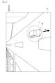
- 2 is an example of an image captured by a first roadside camera of the information processing system shown in FIG. 1 .
- 2 is an example of a virtual image displayed on a display by a virtual image display control unit of the information processing system shown in FIG. 1 .
- 2 is an example of a virtual image displayed on a display by a virtual image display control unit of the information processing system shown in FIG. 1 .
- 4 is an example of an image captured by a second roadside camera of the information processing system shown in FIG. 1 .
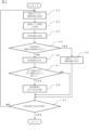
- 2 is a flowchart showing the procedure of an information processing method executed by the information processing system shown in FIG. 1 .
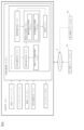
- FIG. 11 is a block diagram showing a configuration of an information processing device according to a second embodiment.
- the information processing system 100 shown in FIG. 1 includes a plurality of roadside cameras 10, a display 20, and a server 30.
- the information processing system 100 uses the controller 3 of the server 30 to display an image including a target vehicle 40 (see FIG. 2) traveling on a road 5 on a display 20 outside the target vehicle 40.
- the information processing system 100 can communicate with the plurality of roadside cameras 10 and the display 20 via a communication network 4.
- the server 30 may be able to communicate with the target vehicle 40 via the communication network 4.
- the number of the plurality of roadside cameras 10 is not particularly limited as long as it is two or more, in this embodiment, for convenience of explanation, the plurality of roadside cameras 10 are described as being composed of two cameras (a first roadside camera 10a and a second roadside camera 10b).
- the controller 3 of the server 30 may transmit data of the captured image V0 and the virtual image V1 to the target vehicle 40, and the captured image V0 and the virtual image V1 may be displayed on an in-vehicle display provided in the target vehicle 40.
- the roadside camera 10 (the first roadside camera 10a and the second roadside camera 10b) is an infrastructure camera arranged along the road 5 to capture the condition of the road 5.
- the imaging direction D0 (the first imaging direction D01 and the second imaging direction D02) of the roadside camera 10 is fixed, but this is not limited thereto, and the roadside camera 10 may be attached so as to be freely rotatable, and the imaging direction D0 may be changed as appropriate.
- the second roadside camera 10b is located on the front side of the first roadside camera 10a.
- the first imaging direction D01 of the first roadside camera 10a is a direction toward the front side in the traveling route of the target vehicle 40.
- the second imaging direction D02 of the second roadside camera 10b is a direction toward the rear side in the traveling route of the target vehicle 40. That is, the imaging direction angle difference ⁇ 1, which is the relative angle of the second imaging direction D02 with respect to the first imaging direction D01, is 180°. Therefore, the second imageable range X2 of the second roadside camera 10b is located in front of the first imageable range X1 of the first roadside camera 10a.
- the imageable range X of the roadside camera 10 is determined by the imaging direction D0 and imageable range of the roadside camera 10.
- the area between the first imageable range X1 and the second imageable range X2 is a blind spot B that cannot be imaged by the roadside camera 10.
- the term “forward side” refers to the direction downstream in the traveling direction of the target vehicle 40 on the traveling path of the target vehicle 40.
- the term “rearward side” refers to the direction upstream in the traveling direction of the target vehicle 40 on the traveling path of the target vehicle 40.
- the first imaging direction D01 is the imaging direction of the first roadside camera 10a when the target vehicle 40 leaves the first imaging range X1 of the first roadside camera 10a
- the second imaging direction D02 is the imaging direction of the second roadside camera 10b when the target vehicle 40 enters the second imaging range X2 of the second roadside camera 10b.
- the image V0 captured by the roadside camera 10 may be a moving image (video), or may be a still image that is continuously switched at a predetermined interval.
- the display 20 shown in FIG. 1 is a display for a user to remotely monitor a target vehicle 40 that is the target of monitoring.
- the user can select a target vehicle 40 to be monitored from among the vehicles displayed on the display 20, and transmit the selection result to the server 30 via a communication unit (not shown) of the display 20.
- a vehicle that can communicate with the server 30 may be set in advance as a target vehicle 40.
- the user may also communicate with the driver of the target vehicle 40 while checking the driving status of the target vehicle 40 via the display 20, and assist in driving the target vehicle 40.
- the user may also remotely control the driving of the target vehicle 40 while checking the driving status of the target vehicle 40 via the display 20.
- the server 30 also has a map database 1, an infrastructure database 2, and a controller 3.
- the map database 1 stores high-precision three-dimensional map information including the position information of various facilities and specific points.
- the infrastructure database 2 also stores roadside camera information for each of the multiple roadside cameras 10 (first roadside camera 10a and second roadside camera 10b).
- the roadside camera information includes the imaging direction D0 and imaging range of each roadside camera 10.
- the roadside camera information may also include the installation position of each roadside camera 10.
- the controller 3 also controls the image to be displayed on the display 20 based on the map information in the map database 1, the roadside camera information in the infrastructure database 2, and the captured image captured by the roadside camera 10.
- the target vehicle 40 has an on-board sensor 41 and a vehicle position detection unit 42.
- the on-board sensor 41 is a camera or radar mounted on the target vehicle 40.
- the on-board sensor 41 detects moving objects and obstacles around the target vehicle 40.
- the moving objects are, for example, other vehicles, bicycles, or pedestrians.
- the vehicle position detection unit 42 is composed of a GPS unit, a gyro sensor, and a vehicle speed sensor.
- the vehicle position detection unit 42 detects the current vehicle position of the target vehicle 40.
- the controller 3 of the server 30 has a communication unit 31, a captured image acquisition unit 32, a roadside camera information acquisition unit 33, a vehicle position acquisition unit 34, a vehicle position determination unit 35, and an image display control unit 36.
- the controller 3 executes each function of the communication unit 31, the captured image acquisition unit 32, the roadside camera information acquisition unit 33, the vehicle position acquisition unit 34, the vehicle position determination unit 35, and the image display control unit 36 by executing a program stored in the ROM using the CPU.
- the communication unit 31 exchanges information with the first roadside camera 10a, the second roadside camera 10b, and the display 20 via the communication network 4. Specifically, the communication unit 31 receives data of the captured image V0 (see Figures 3 and 6) from the first roadside camera 10a and the second roadside camera 10b. The communication unit 31 also transmits image data to the display 20 based on a control command from the image display control unit 36.
- the communication unit 31 may also exchange information with the target vehicle 40 via the communication network 4. Specifically, the communication unit 31 receives the detection results of the on-board sensor 41 from the target vehicle 40. The communication unit 31 also receives vehicle information from the target vehicle 40 indicating the driving conditions of the target vehicle 40. The vehicle information includes the vehicle position of the target vehicle 40. The vehicle information may also include at least one of the vehicle speed, acceleration, direction, turn signal status, and stop lamp status of the target vehicle 40.
- the captured image acquisition unit 32 acquires a first captured image V01 (see FIG. 3) captured by the first roadside camera 10a and a second captured image V02 (see FIG. 6) captured by the second roadside camera 10b based on the image data received by the communication unit 31.
- the roadside camera information acquisition unit 33 acquires roadside camera information of the first roadside camera 10a and the second roadside camera 10b from the infrastructure database 2.
- the vehicle position acquisition unit 34 acquires the vehicle position of the target vehicle 40 based on the captured image V0 acquired by the captured image acquisition unit 32, with reference to the map information in the map database 1 and the roadside camera information in the infrastructure database 2. Specifically, as shown in Fig. 3, if the target vehicle 40 is included in the first captured image V01 of the first roadside camera 10a, the vehicle position acquisition unit 34 identifies the vehicle position of the target vehicle 40 within the first imageable range X1 with reference to the map information and roadside camera information. In addition, as shown in Fig.
- the vehicle position acquisition unit 34 identifies the vehicle position of the target vehicle 40 within the second imageable range X2 with reference to the map information and roadside camera information. Furthermore, when the target vehicle 40 is traveling in the blind spot area B and the controller 3 cannot acquire an image, the vehicle position acquisition unit 34 estimates the vehicle position of the target vehicle 40 based on the vehicle speed and direction when the target vehicle 40 leaves the first imageable range X1. That is, the vehicle position acquisition unit 34 acquires vehicle information of the target vehicle 40 from the captured image V0, and acquires the vehicle position of the target vehicle 40 based on the vehicle information.
- the vehicle position acquisition unit 34 may also acquire the vehicle position of the target vehicle 40 based on the vehicle information received from the target vehicle 40 by the communication unit 31.
- the vehicle position determination unit 35 also determines whether the target vehicle 40 is traveling in the imageable range X of the roadside camera 10 (the first imageable range X1 or the second imageable range X2) based on the roadside camera information acquired from the roadside camera information acquisition unit 33 and the vehicle position acquired from the vehicle position acquisition unit 34. That is, the vehicle position determination unit 35 determines whether the target vehicle 40 is traveling in the imageable range X of the roadside camera 10 based on the imageable range X of the roadside camera 10 relative to the road 5 and the vehicle position.
- the image display control unit 36 also controls the image data that the communication unit 31 transmits to the display 20 based on the determination result of the vehicle position determination unit 35. In other words, the image display control unit 36 controls the image to be displayed on the display 20.
- the image display control unit 36 has a captured image display control unit 36a and a virtual image display control unit 36b.
- the captured image display control unit 36a When the target vehicle 40 is traveling within the imageable range X, the captured image display control unit 36a generates a control command to display an captured image V0 including the target vehicle 40 on the display 20. Specifically, when the target vehicle 40 is traveling within the first imageable range X1, the captured image display control unit 36a displays a first captured image V01 on the display 20. Furthermore, when the target vehicle 40 is traveling within the second imageable range X2, the captured image display control unit 36a displays a second captured image V02 on the display 20. In other words, the captured image display control unit 36a selects an image including the target vehicle 40 from the multiple captured images V0 captured by each of the multiple roadside cameras 10, and displays it on the display 20.
- the virtual image display control unit 36b displays a virtual image V1 of the target vehicle 40 displayed in a predetermined display direction D1 on the display 20 (see Figures 4 and 5).
- the virtual image V1 is an image in which an icon or CG of the target vehicle 40 is synthesized onto an omnidirectional image or 3DCG (omnidirectional spatial image) generated based on map information including the road 5 on which the target vehicle 40 is traveling.
- the virtual image display control unit 36b determines whether the first imaging direction D01 of the first roadside camera 10a is different from the second imaging direction D02 of the second roadside camera 10b in which the target vehicle 40 is located. Then, as shown in FIG. 2, when the first imaging direction D01 and the second imaging direction D02 are different, the virtual image display control unit 36b updates (changes) the display direction D1 of the virtual image V1 one or more times so that the second display direction D12 when the target vehicle 40 is at the second vehicle position P02 forward of the first vehicle position P01 is closer to the second imaging direction D02 than the first display direction D11 when the target vehicle 40 is at the first vehicle position P01.
- the first vehicle position P01 is a position near the position of the first roadside camera 10a
- the second vehicle position P02 is a position near the position of the second roadside camera 10b. That is, the virtual image display control unit 36b updates the virtual image V1 so that the display direction D1 of the virtual image V1 approaches the second imaging direction D02 as the vehicle position of the target vehicle 40 traveling in the blind spot area B approaches the second imaging range X2.
- the virtual image display control unit 36b generates a first virtual image V11 including the target vehicle 40 that has exited the first imageable range X1, as shown in FIG. 4.
- the first virtual image V11 is an image generated on the assumption that an image has been captured from the first virtual imaging position P11 toward the first display direction D11.
- the first relative angle ⁇ 21 of the first display direction D11 with respect to the first imaging direction D01 is set to a value greater than 0° and smaller than the imaging direction angle difference ⁇ 1.
- the virtual image display control unit 36b also switches the first virtual image V11 shown in FIG. 4 to the second virtual image V12 shown in FIG. 5 at a predetermined time.
- the second virtual image V12 is an image generated on the assumption that an image is captured from the second virtual imaging position P12 toward the second display direction D12.
- the second relative angle ⁇ 22 of the second display direction D12 with respect to the first imaging direction D01 is set to a value greater than 0° and smaller than the imaging direction angle difference ⁇ 1.
- the second display direction D12 is closer to the second imaging direction D02 than the first display direction D11. That is, the second relative angle ⁇ 22 is greater than the first relative angle ⁇ 21 and closer to the imaging direction angle difference ⁇ 1. That is, the virtual image display control unit 36b updates the first display direction D11 of the first virtual image V11 displayed on the display 20 to the second display direction D12 of the second virtual image V12 at a predetermined time.
- the image display control unit 36 displays images on the display 20 in the following order: the first captured image V01 shown in FIG. 3, the first virtual image V11 shown in FIG. 4, the second virtual image V12 shown in FIG. 5, and the second captured image V02 shown in FIG. 6.
- the target vehicle 40 which initially appears to be moving away from the screen to the back, appears to gradually approach the front of the screen as the target vehicle 40 moves.
- the virtual image display control unit 36b switches the first virtual image V11 shown in FIG. 4 to the second virtual image V12 shown in FIG. 5. More specifically, the virtual image display control unit 36b calculates the blind spot driving time from when the target vehicle 40 leaves the first imageable range X1 to when it enters the second imageable range X2. Then, the virtual image display control unit 36b calculates the display angle change speed by dividing the imaging direction angle difference ⁇ 1 between the first imaging direction D01 and the second imaging direction D02 by the blind spot driving time, and changes the display direction D1 at a timing according to the display angle change speed. Additionally, the virtual image display control unit 36b may continuously change the display direction D1 of the virtual image V1 at a predetermined interval (e.g., every second) in accordance with the display angle change speed.
- a predetermined interval e.g., every second
- the virtual image display control unit 36b also acquires the exit time when the target vehicle 40 exits the first imageable range X1, and calculates the entry time when the target vehicle 40 enters the second imageable range X2 based on the vehicle information (the speed, acceleration, etc. of the target vehicle 40) and the exit time.
- information T indicating the entry time is displayed on the virtual image V1. Note that in the examples shown in FIGS. 3 and 4, the information T is text information indicating the remaining time until the target vehicle 40 enters the second imageable range X2, but is not limited to this, and the information T may be information indicating the time when the target vehicle 40 enters the second imageable range X2.
- the image (CG) of the target vehicle 40 moves on the road 5 according to the vehicle position estimated by the vehicle position acquisition unit 34. That is, the first virtual image V11 and the second virtual image V12 include information indicating the vehicle position and orientation of the target vehicle 40.
- the virtual image display control unit 36b displays the target vehicle 40 on the first virtual image V11 and the second virtual image V12 by surrounding it with a frame line L.
- the frame line L may be displayed in a conspicuous color such as red.
- the virtual image display control unit 36b may highlight the target vehicle 40. That is, the virtual image display control unit 36b displays the target vehicle 40 in a manner that makes it distinguishable from other vehicles.
- the virtual image display control unit 36b displays the driving route R of the target vehicle 40 by superimposing it on the first virtual image V11 and the second virtual image V12. In addition, the virtual image display control unit 36b displays the first image capture range X1 on the first virtual image V11. In addition, the virtual image display control unit 36b displays the second image capture range X2 on the second virtual image V12.
- the virtual image display control unit 36b may also display information indicating at least one of the vehicle position, orientation, turn signal status, and stop lamp status of the target vehicle 40 on the virtual image V1 based on the vehicle information acquired from the target vehicle 40.
- the virtual image display control unit 36b may determine whether or not a moving object is present around the target vehicle 40 based on the detection results of the on-board sensor 41. If a moving object is present, the virtual image display control unit 36b may display vehicle surroundings information indicating either or both of the position and shape of the moving object in the virtual image V1.
- step S4 the vehicle position determination unit 35 determines whether the target vehicle 40 is traveling within the image capture range X of the roadside camera 10 based on the image capture range X and the vehicle position.
- step S7 the virtual image display control unit 36b determines whether the first imaging direction D01 of the first roadside camera 10a and the second imaging direction D02 of the second roadside camera 10b are different.
- step S8 the virtual image display control unit 36b updates (changes) the display direction D1 of the virtual image V1 so that the second display direction D12 when the target vehicle 40 is at the second vehicle position P02 is closer to the second imaging direction D02 than the first display direction D11 when the target vehicle 40 is at the first vehicle position P01.
- the virtual image display control unit 36b determines in step S7 that "the first imaging direction D01 and the second imaging direction D02 are the same"
- the virtual image display control unit 36b does not update (change) the display direction D1 of the virtual image V1. That is, the information processing system 100 skips the process of step S8.
- step S9 the information processing system 100 determines whether the target vehicle 40 has arrived at the destination. If the target vehicle 40 has arrived at the destination, i.e., if remote monitoring of the target vehicle 40 has ended, the process ends. On the other hand, if the target vehicle 40 has not arrived at the destination, the process returns to step S1.
- the information processing system 100 determines whether or not the first imaging direction D01 of the first roadside camera 10a with respect to the road 5 when the target vehicle 40 leaves the first imageable range X1 of the first roadside camera 10a is different from the second imaging direction D02 with respect to the road 5 when the target vehicle 40 enters the second imageable range X2 of the second roadside camera 10b.
- the information processing system 100 changes the display direction D1 of the virtual image V1 in accordance with the position of the target vehicle 40 so that the second display direction D12 when the target vehicle 40 is at the second vehicle position P02 near the position of the second roadside camera 10b, which is forward of the first vehicle position P01, is closer to the second imaging direction D02 than the first display direction D11 when the target vehicle 40 is at the first vehicle position P01 near the position of the first roadside camera 10a. That is, when the first captured image V01 displayed on the display 20 is switched to the virtual image V1, the display direction D1 of the virtual image V1 gradually or continuously approaches the second captured image direction D02 from the first captured image direction D01.
- the information processing system 100 displays the virtual image V1 on the display 20 when the target vehicle 40 is not traveling within the imaging range X, so that the user can check the traveling status of the target vehicle 40 even when the roadside camera 10 cannot image the target vehicle 40.
- the information processing system 100 acquires the exit time when the target vehicle 40 exits the first imageable range X1, calculates the entry time when the target vehicle 40 enters the second imageable range X2 based on the vehicle information and the exit time, and displays a virtual image V1 including information T indicating the entry time on the display 20 when the target vehicle 40 is traveling between the first imageable range X1 and the second imageable range X2. This allows the user to know the timing (time) when the virtual image V1 switches to the second imaged image V02 even while the virtual image V1 is being displayed on the display 20.
- the information processing system 100 calculates the blind spot driving time from when the target vehicle 40 leaves the first imageable range X1 to when it enters the second imageable range X2, calculates the imaging direction angle difference ⁇ 1 of the second imaging direction D02 with respect to the first imaging direction D01, calculates the display angle change speed by dividing the imaging direction angle difference ⁇ 1 by the blind spot driving time, and changes the display direction at a timing based on the display angle change speed.
- the display direction D1 of the virtual image V1 changes to approach the second imaging direction D2 in accordance with the movement of the target vehicle 40, so that the user can easily identify the target vehicle 40 even after the virtual image V1 has switched to the second captured image V02.
- the virtual image V1 is an image in which an icon or CG of the target vehicle 40 is synthesized onto an omnidirectional image or 3DCG (omnidirectional spatial image) generated based on map information including the road 5 on which the target vehicle 40 is traveling. This allows the user to easily visually grasp the driving conditions of the target vehicle 40 even when the target vehicle 40 is traveling in the blind spot area B.
- the virtual image V1 includes information indicating at least one of the vehicle position, direction, turn signal status, and stop lamp status of the target vehicle 40. This allows the user to easily visually grasp the driving conditions of the target vehicle 40 even when the target vehicle 40 is driving in the blind spot area B.
- the information processing system 100 may also acquire the detection results of the on-board sensor 41 of the target vehicle 40, and determine whether or not there is a moving object around the target vehicle 40 based on the detection results, and if there is a moving object, may display vehicle surroundings information indicating either or both of the position and shape of the moving object in the virtual image V1. This allows the user to visually confirm information about the driving environment including moving objects around the target vehicle 40, even when the target vehicle 40 is driving in the blind spot area B.
- the information processing system 100 displays the target vehicle 40 included in either or both of the captured image V0 and the virtual image V1 by surrounding it with a frame line L or highlighting it, thereby displaying the target vehicle 40 in a manner that makes it distinguishable from other vehicles. This allows the user to easily identify the target vehicle 40.
- the information processing system 100 displays the travel route R of the target vehicle 40 superimposed on either or both of the captured image V0 and the virtual image V1. This allows the user to visually grasp the travel route R of the target vehicle 40.
- the information processing device 200 is mounted on the target vehicle 40.
- the display 20 is an in-vehicle display provided in the target vehicle 40. That is, the controller 3 of the information processing device 200 displays the captured image V0 and the virtual image V1 on the display 20 provided in the target vehicle 40.
- the target vehicle 40 also has a map database 1, an infrastructure database 2, an on-board sensor 41, and a vehicle position detection unit 42.
- the information processing device 200 displays the captured image V0 and the virtual image V1 on the display 20 provided in the target vehicle 40. This allows the driver of the target vehicle 40 to check the driving conditions of his/her own vehicle (target vehicle 40) on the display 20 inside the vehicle.
- Information processing system 200 ... Information processing device 3... Controller 10... Roadside camera 20... Display 30... Server 32... Captured image acquisition unit 33... Roadside camera information acquisition unit 34... Vehicle position acquisition unit 35... Vehicle position determination unit 36a... Captured image display control unit 36b... Virtual image display control unit 40... Target vehicle D0... Capture direction D1... Display direction R... Travel route L... Frame line T... Information indicating entry time V0... Captured image V1... Virtual image X... Capturing range ⁇ 1... Capture direction angle difference
Landscapes
- Engineering & Computer Science (AREA)
- Multimedia (AREA)
- Signal Processing (AREA)
- Traffic Control Systems (AREA)
Abstract
情報処理システム100は、対象車両40が路側カメラ10の撮像可能範囲Xを走行している場合は撮像画像V0をディスプレイ20に表示し、対象車両40が撮像可能範囲X以外を走行している場合は、仮想画像V1をディスプレイ20に表示し、第1の路側カメラ10aの第1の撮像方向D01と、第1の路側カメラ10aの前方側に位置する第2の路側カメラ10bの第2の撮像方向D02とが異なるか否かを判定し、第1の撮像方向D01と第2の撮像方向D02とが異なるときは、対象車両40が第1の車両位置P01にいるときの第1の表示方向D11よりも、対象車両40が第1の車両位置P01の前方側の第2の車両位置P02にいるときの第2の表示方向D12の方が第2の撮像方向D02に近づくように、仮想画像V1の表示方向D1を変更する。
Description
本発明は、情報処理方法、情報処理システム及び情報処理装置に関するものである。
特許文献1には、複数箇所に設置された監視カメラによって監視対象となる車両を撮影する移動体監視システムが記載されている。特許文献1に記載の移動体監視システムは、監視対象となる車両を追随して監視できるように、複数の監視カメラの中で、当該車両を撮影可能な監視カメラを適宜選択して撮影を行う。
しかしながら、特許文献1の移動体監視システムでは、対象車両の移動に伴って、撮影を実行する監視カメラを切り替えたときに、撮像画像を見ているユーザが、当該画像がどの方向から撮像されているのかをすぐに把握できず、対象車両を見失ってしまう可能性がある。
本発明が解決しようとする課題は、対象車両を撮像する路側カメラ(インフラカメラ)を切り替えるときに、切り替え後の撮像画像を見ているユーザが対象車両を容易に特定できる情報処理方法、情報処理システム及び情報処理装置を提供することである。
本発明は、対象車両が撮像可能範囲以外を走行している場合は、道路に対して所定の表示方向で表示した対象車両及び道路の仮想画像をディスプレイに表示し、対象車両が第1の路側カメラの第1の撮像可能範囲を退出したときの道路に対する第1の路側カメラの第1の撮像方向と、対象車両が第1の路側カメラの対象車両の進行方向の前方側に位置する第2の路側カメラの第2の撮像可能範囲に進入するときの道路に対する第2の路側カメラの第2の撮像方向とが異なるか否かを判定し、第1の撮像方向と第2の撮像方向とが異なるときは、対象車両が第1の路側カメラの位置付近の第1の車両位置にいるときの第1の表示方向よりも、対象車両が第1の車両位置の前方側の、第2の路側カメラの位置付近の第2の車両位置にいるときの第2の表示方向の方が第2の撮像方向に近づくように、対象車両の位置に合わせて、仮想画像の所定の表示方向を変更することによって上記課題を解決する。
本発明によれば、対象車両を撮像する路側カメラを切り替えるときに、切り替え後の撮像画像を見ているユーザが対象車両を容易に特定できるという効果を奏する。
以下、本発明の実施形態を図面に基づいて説明する。
《第1実施形態》
第1実施形態に係る情報処理システム100について、図1~7に基づいて説明する。
図1に示す情報処理システム100は、複数の路側カメラ10、ディスプレイ20及びサーバ30を有する。情報処理システム100は、サーバ30のコントローラ3を用いて、道路5を走行する対象車両40(図2参照)を含む画像を対象車両40の外部にあるディスプレイ20に表示する。情報処理システム100は、通信網4を介して、複数の路側カメラ10及びディスプレイ20と通信可能である。また、破線で示すように、サーバ30は通信網4を介して対象車両40と通信可能であってもよい。なお、複数の路側カメラ10の数は2つ以上であれば特に限定されないが、本実施形態では、説明の便宜上、複数の路側カメラ10が2つのカメラ(第1の路側カメラ10a及び第2の路側カメラ10b)によって構成されているものとして説明する。なお、サーバ30のコントローラ3は、撮像画像V0及び仮想画像V1のデータを対象車両40に送信し、撮像画像V0及び仮想画像V1を対象車両40に設けられた車内ディスプレイに表示してもよい。
《第1実施形態》
第1実施形態に係る情報処理システム100について、図1~7に基づいて説明する。
図1に示す情報処理システム100は、複数の路側カメラ10、ディスプレイ20及びサーバ30を有する。情報処理システム100は、サーバ30のコントローラ3を用いて、道路5を走行する対象車両40(図2参照)を含む画像を対象車両40の外部にあるディスプレイ20に表示する。情報処理システム100は、通信網4を介して、複数の路側カメラ10及びディスプレイ20と通信可能である。また、破線で示すように、サーバ30は通信網4を介して対象車両40と通信可能であってもよい。なお、複数の路側カメラ10の数は2つ以上であれば特に限定されないが、本実施形態では、説明の便宜上、複数の路側カメラ10が2つのカメラ(第1の路側カメラ10a及び第2の路側カメラ10b)によって構成されているものとして説明する。なお、サーバ30のコントローラ3は、撮像画像V0及び仮想画像V1のデータを対象車両40に送信し、撮像画像V0及び仮想画像V1を対象車両40に設けられた車内ディスプレイに表示してもよい。
路側カメラ10(第1の路側カメラ10a及び第2の路側カメラ10b)は、道路5の状況を撮像するために道路5に沿って配置されているインフラカメラである。本実施形態では、路側カメラ10の撮像方向D0(第1の撮像方向D01及び第2の撮像方向D02)は固定されているが、これに限定されず、路側カメラ10は回動自在に取り付けられ、撮像方向D0が適宜変化してもよい。図2に示す例では、第2の路側カメラ10bは第1の路側カメラ10aの前方側に位置する。また、第1の路側カメラ10aの第1の撮像方向D01は、対象車両40の走行経路における前方側の方向である。一方、第2の路側カメラ10bの第2の撮像方向D02は、対象車両40の走行経路における後方側の方向である。すなわち、第1の撮像方向D01に対する第2の撮像方向D02の相対角度である撮像方向角度差θ1は180°である。よって、第2の路側カメラ10bの第2の撮像可能範囲X2は、第1の路側カメラ10aの第1の撮像可能範囲X1の前方側に位置する。なお、路側カメラ10の撮像可能範囲Xは、路側カメラ10の撮像方向D0及び撮像可能範囲によって決まる。また、第1の撮像可能範囲X1と第2の撮像可能範囲X2との間の領域は、路側カメラ10が撮像できない死角領域Bである。
なお、「前方側」とは、対象車両40の走行経路上における対象車両40の進行方向下流側の方向をいう。また、「後方側」とは、対象車両40の走行経路上における対象車両40の進行方向上流側の方向をいう。
また、第1の撮像方向D01は、対象車両40が第1の路側カメラ10aの第1の撮像可能範囲X1を退出したときの第1の路側カメラ10aの撮像方向である。また、第2の撮像方向D02は、対象車両40が第2の路側カメラ10bの第2の撮像可能範囲X2に進入するときの第2の路側カメラ10bの撮像方向である。
また、路側カメラ10の撮像画像V0は、動画(映像)であってもよく、所定間隔で連続的に切り替わる静止画であってもよい。
なお、「前方側」とは、対象車両40の走行経路上における対象車両40の進行方向下流側の方向をいう。また、「後方側」とは、対象車両40の走行経路上における対象車両40の進行方向上流側の方向をいう。
また、第1の撮像方向D01は、対象車両40が第1の路側カメラ10aの第1の撮像可能範囲X1を退出したときの第1の路側カメラ10aの撮像方向である。また、第2の撮像方向D02は、対象車両40が第2の路側カメラ10bの第2の撮像可能範囲X2に進入するときの第2の路側カメラ10bの撮像方向である。
また、路側カメラ10の撮像画像V0は、動画(映像)であってもよく、所定間隔で連続的に切り替わる静止画であってもよい。
また、図1に示すディスプレイ20は、ユーザが監視対象である対象車両40を遠隔監視するためのディスプレイである。ユーザは、ディスプレイ20に表示された車両の中から監視対象とする対象車両40を選択して、選択結果をディスプレイ20の通信部(図示せず)を介してサーバ30に送信することができる。また、サーバ30と通信可能な車両が予め対象車両40として設定されていてもよい。また、ユーザは、ディスプレイ20を介して、対象車両40の走行状況を確認しながら、対象車両40のドライバと通信を行い、対象車両40の運転を支援してもよい。また、ユーザは、ディスプレイ20を介して、対象車両40の走行状況を確認しながら、対象車両40の運転を遠隔制御してもよい。
また、サーバ30は、地図データベース1、インフラデータベース2及びコントローラ3を有する。地図データベース1は、各種施設や特定の地点の位置情報を含む三次元高精度地図情報を格納する。また、インフラデータベース2は、複数の路側カメラ10(第1の路側カメラ10a及び第2の路側カメラ10b)の各々の路側カメラ情報を格納する。路側カメラ情報は、路側カメラ10の各々の撮像方向D0及び撮像範囲を含む。また、路側カメラ情報は、路側カメラ10の各々の設置位置を含んでもよい。また、コントローラ3は、地図データベース1の地図情報、インフラデータベース2の路側カメラ情報及び路側カメラ10が撮像した撮像画像に基づいて、ディスプレイ20に表示する画像を制御する。
対象車両40は車載センサ41及び車両位置検出部42を有する。車載センサ41は、対象車両40の搭載されるカメラ又はレーダである。車載センサ41は、対象車両40の周囲の移動物及び障害物を検出する。なお、移動物は、例えば、他車両、自転車又は歩行者等である。また、車両位置検出部42は、GPSユニット、ジャイロセンサ及び車速センサから構成されている。車両位置検出部42は、対象車両40の現在の車両位置を検出する。
サーバ30のコントローラ3は、通信部31、撮像画像取得部32、路側カメラ情報取得部33、車両位置取得部34、車両位置判定部35及び画像表示制御部36を有する。コントローラ3は、ROMに格納されたプログラムをCPUにより実行することにより、通信部31、撮像画像取得部32、路側カメラ情報取得部33、車両位置取得部34、車両位置判定部35及び画像表示制御部36の各機能を実行する。
通信部31は、通信網4を介して、第1の路側カメラ10a、第2の路側カメラ10b及びディスプレイ20との間で情報の授受を行う。具体的には、通信部31は、第1の路側カメラ10a及び第2の路側カメラ10bから撮像画像V0(図3、6参照)のデータを受信する。また、通信部31は、画像表示制御部36の制御指令に基づいて、画像データをディスプレイ20に送信する。
また、通信部31は、通信網4を介して、対象車両40と情報の授受を行ってもよい。具体的には、通信部31は、対象車両40から車載センサ41の検出結果を受信する。また、通信部31は、対象車両40から対象車両40の走行状況を示す車両情報を受信する。車両情報には対象車両40の車両位置が含まれる。また、車両情報は、対象車両40の車速、加速度、向き、ウィンカーの状態及び停止ランプの状態の少なくともいずれか1つを含んでいてもよい。
撮像画像取得部32は、通信部31が受信した画像データに基づいて、第1の路側カメラ10aが撮像した第1の撮像画像V01(図3参照)及び第2の路側カメラ10bが撮像した第2の撮像画像V02(図6参照)を取得する。
また、路側カメラ情報取得部33は、インフラデータベース2から第1の路側カメラ10a及び第2の路側カメラ10bの路側カメラ情報を取得する。
また、車両位置取得部34は、地図データベース1の地図情報及びインフラデータベース2の路側カメラ情報を参照して、撮像画像取得部32が取得した撮像画像V0に基づき、対象車両40の車両位置を取得する。具体的には、図3に示すように、第1の路側カメラ10aの第1の撮像画像V01に対象車両40が含まれている場合は、車両位置取得部34は、地図情報及び路側カメラ情報を参照して、第1の撮像可能範囲X1内の対象車両40の車両位置を特定する。また、図6に示すように、第2の路側カメラ10bの第2の撮像画像V02に対象車両40が含まれている場合は、車両位置取得部34は、地図情報及び路側カメラ情報を参照して、第2の撮像可能範囲X2内の対象車両40の車両位置を特定する。また、対象車両40が死角領域Bを走行しており、コントローラ3が撮像画像を取得できないときは、車両位置取得部34は、対象車両40が第1の撮像可能範囲X1を退出するときの車速及び向きに基づいて、対象車両40の車両位置を推測する。すなわち、車両位置取得部34は、撮像画像V0から対象車両40の車両情報を取得し、車両情報に基づいて対象車両40の車両位置を取得する。
また、車両位置取得部34は、通信部31が対象車両40から受信した車両情報に基づいて対象車両40の車両位置を取得してもよい。
また、車両位置判定部35は、路側カメラ情報取得部33から取得した路側カメラ情報及び車両位置取得部34から取得した車両位置に基づいて、対象車両40が路側カメラ10の撮像可能範囲X(第1の撮像可能範囲X1又は第2の撮像可能範囲X2)を走行しているか否かを判定する。すなわち、車両位置判定部35は、道路5に対する路側カメラ10の撮像可能範囲X及び車両位置に基づいて、対象車両40が路側カメラ10の撮像可能範囲Xを走行しているか否かを判定する。
また、画像表示制御部36は、車両位置判定部35の判定結果に基づいて、通信部31がディスプレイ20に送信する画像データを制御する。すなわち、画像表示制御部36は、ディスプレイ20に表示する画像を制御する。画像表示制御部36は、撮像画像表示制御部36a及び仮想画像表示制御部36bを有する。
撮像画像表示制御部36aは、対象車両40が撮像可能範囲Xを走行している場合は、対象車両40を含む撮像画像V0をディスプレイ20に表示するための制御指令を生成する。具体的には、撮像画像表示制御部36aは、対象車両40が第1の撮像可能範囲X1を走行している場合は、第1の撮像画像V01をディスプレイ20に表示する。また、撮像画像表示制御部36aは、対象車両40が第2の撮像可能範囲X2を走行している場合は、第2の撮像画像V02をディスプレイ20に表示する。すなわち、撮像画像表示制御部36aは、複数の路側カメラ10の各々が撮像した複数の撮像画像V0から、対象車両40が含まれる画像を選択してディスプレイ20に表示する。
仮想画像表示制御部36bは、対象車両40が撮像可能範囲X以外を走行している場合は、所定の表示方向D1で表示した対象車両40の仮想画像V1をディスプレイ20に表示する(図4、5参照)。仮想画像V1は、対象車両40が走行する道路5を含む地図情報に基づいて生成された全方位画像または3DCG(全方位空間画像)上に対象車両40のアイコンまたはCGを合成した画像である。
仮想画像表示制御部36bは、第1の路側カメラ10aの第1の撮像方向D01と、対象車両40が第2の路側カメラ10bの第2の撮像方向D02とが異なるか否かを判定する。そして、図2に示すように、仮想画像表示制御部36bは、第1の撮像方向D01と第2の撮像方向D02とが異なるときは、対象車両40が第1の車両位置P01にいるときの第1の表示方向D11よりも、対象車両40が第1の車両位置P01の前方側の第2の車両位置P02にいるときの第2の表示方向D12の方が第2の撮像方向D02に近づくように、仮想画像V1の表示方向D1を1回以上更新(変更)する。第1の車両位置P01は、第1の路側カメラ10aの位置付近の位置であり、第2の車両位置P02は、第2の路側カメラ10bの位置付近の位置である。すなわち、仮想画像表示制御部36bは、死角領域Bを走行する対象車両40の車両位置が第2の撮像可能範囲X2に近づく程、仮想画像V1の表示方向D1が第2の撮像方向D02に近づくように、仮想画像V1を更新する。
具体的には、まず、仮想画像表示制御部36bは、図4に示すように、第1の撮像可能範囲X1から退出した対象車両40を含む第1の仮想画像V11を生成する。図2に示すように、第1の仮想画像V11は、第1の仮想撮像位置P11から第1の表示方向D11に向かって撮像されたと仮定して生成された画像である。なお、第1の撮像方向D01に対する第1の表示方向D11の第1の相対角度θ21は、0°より大きく、かつ、撮像方向角度差θ1より小さい値となるように設定される。
また、仮想画像表示制御部36bは、図4に示す第1の仮想画像V11を、所定の時点で、図5に示す第2の仮想画像V12に切替える。図2に示すように、第2の仮想画像V12は、第2の仮想撮像位置P12から第2の表示方向D12に向かって撮像されたと仮定して生成された画像である。第1の撮像方向D01に対する第2の表示方向D12の第2の相対角度θ22は、0°より大きく、かつ、撮像方向角度差θ1より小さい値となるように設定される。また、第2の表示方向D12は第1の表示方向D11よりも第2の撮像方向D02に近い。すなわち、第2の相対角度θ22は、第1の相対角度θ21よりも大きく、撮像方向角度差θ1に近い。すなわち、仮想画像表示制御部36bは、ディスプレイ20に表示される第1の仮想画像V11の第1の表示方向D11を、所定の時点で、第2の仮想画像V12の第2の表示方向D12に更新する。
すなわち、画像表示制御部36は、図3に示す第1の撮像画像V01、図4に示す第1の仮想画像V11、図5に示す第2の仮想画像V12、及び、図6に示す第2の撮像画像V02の順序で、画像をディスプレイ20に表示する。これにより、ディスプレイ20を見ているユーザにとっては、初めは画面の奥側に遠ざかっていくように見えた対象車両40が、対象車両40が移動するにつれて、徐々に画面の手前側に接近してくるように見える。
なお、図2に示す例では、仮想画像表示制御部36bは、対象車両40が第1の車両位置P01と第2の車両位置P02との間を走行しているとき、又は、対象車両40が第2の車両位置P02に到達したときに、図4に示す第1の仮想画像V11を、図5に示す第2の仮想画像V12に切替える。より具体的には、仮想画像表示制御部36bは、対象車両40が第1の撮像可能範囲X1を退出してから第2の撮像可能範囲X2に進入するまでの死角走行時間を算出する。そして、仮想画像表示制御部36bは、第1の撮像方向D01と第2の撮像方向D02との撮像方向角度差θ1を死角走行時間で除した表示角度変更速度を算出し、表示角度変更速度に応じたタイミングで表示方向D1を変更する。また、仮想画像表示制御部36bは、表示角度変更速度に合わせて、仮想画像V1の表示方向D1を所定間隔(例えば、1秒毎)で連続的に変更してもよい。
また、仮想画像表示制御部36bは、対象車両40が第1の撮像可能範囲X1を退出する退出時間を取得し、車両情報(対象車両40の車速、加速度等)及び退出時間に基づいて対象車両40が第2の撮像可能範囲X2に進入する進入時間を算出する。そして、対象車両40が第1の撮像可能範囲X1と第2の撮像可能範囲X2との間を走行しているときは、進入時間を示す情報Tを仮想画像V1上に表示する。なお、図3、4に示す例では、情報Tは、対象車両40が第2の撮像可能範囲X2に進入するまでの残り時間を示す文字情報であるが、これに限定されず、情報Tは、対象車両40が第2の撮像可能範囲X2に進入する時刻を示す情報であってもよい。
また、第1の仮想画像V11及び第2の仮想画像V12上では、対象車両40の画像(CG)は、車両位置取得部34が推定した車両位置に応じて道路5を移動する。すなわち、第1の仮想画像V11及び第2の仮想画像V12は、対象車両40の車両位置及び向きを示す情報を含む。また、仮想画像表示制御部36bは、第1の仮想画像V11及び第2の仮想画像V12上の対象車両40を枠線Lで囲んで表示する。枠線Lは赤等の目立つ色で表示されてもよい。また、仮想画像表示制御部36bは、対象車両40をハイライト表示してもよい。すなわち、仮想画像表示制御部36bは、対象車両40を他車両と区別可能な態様で表示する。また、仮想画像表示制御部36bは、第1の仮想画像V11及び第2の仮想画像V12に対象車両40の走行経路Rを重畳して表示する。また、仮想画像表示制御部36bは、第1の仮想画像V11上に第1の撮像可能範囲X1を表示する。また、仮想画像表示制御部36bは、第2の仮想画像V12上に第2の撮像可能範囲X2を表示する。
また、仮想画像表示制御部36bは、対象車両40から取得した車両情報に基づいて、対象車両40の車両位置、向き、ウィンカーの状態及び停止ランプの状態の少なくともいずれか1つを示す情報を仮想画像V1上に表示してもよい。
さらに、仮想画像表示制御部36bは、車載センサ41の検出結果に基づき、対象車両40の周囲に移動物が存在するか否かを判定してもよい。そして、移動物が存在する場合は、仮想画像表示制御部36bは、移動物の位置及び形状のうちいずれか一方又は両方を示す車両周囲情報を仮想画像V1に表示してもよい。
次に、図7のフローチャートを用いて、情報処理システム100が実行する情報表示方法の手順を説明する。
まず、ステップS1において、撮像画像取得部32は、複数の路側カメラ10の各々が撮像した撮像画像V0を取得する。
次に、ステップS2において、路側カメラ情報取得部33は、複数の路側カメラ10の各々の撮像方向D0及び撮像可能範囲Xを含む路側カメラ情報を取得する。
次に、ステップS3において、車両位置取得部34は、撮像画像V0又は対象車両40から取得した車両情報に基づいて対象車両40の車両位置を取得する。
まず、ステップS1において、撮像画像取得部32は、複数の路側カメラ10の各々が撮像した撮像画像V0を取得する。
次に、ステップS2において、路側カメラ情報取得部33は、複数の路側カメラ10の各々の撮像方向D0及び撮像可能範囲Xを含む路側カメラ情報を取得する。
次に、ステップS3において、車両位置取得部34は、撮像画像V0又は対象車両40から取得した車両情報に基づいて対象車両40の車両位置を取得する。
そして、ステップS4において、車両位置判定部35は、撮像可能範囲X及び車両位置に基づいて、対象車両40が路側カメラ10の撮像可能範囲Xを走行しているか否かを判定する。
ステップS4において、車両位置判定部35が「対象車両40は路側カメラ10の撮像可能範囲Xを走行している」と判定した場合は、ステップS5において、撮像画像表示制御部36aは、対象車両40を含む撮像画像V0をディスプレイ20に表示する。その後、処理はステップS9に進む。
また、S4において、車両位置判定部35が「対象車両40は路側カメラ10の撮像可能範囲X以外を走行している」と判定した場合は、ステップS6において、仮想画像表示制御部36bは、所定の表示方向D1で表示した対象車両40の仮想画像V1をディスプレイ20に表示する。
そして、ステップS7において、仮想画像表示制御部36bは、第1の路側カメラ10aの第1の撮像方向D01と第2の路側カメラ10bの第2の撮像方向D02とが異なるか否かを判定する。
ステップS7において、仮想画像表示制御部36bが「第1の撮像方向D01と第2の撮像方向D02とが異なる」と判定した場合は、ステップS8において、仮想画像表示制御部36bは、対象車両40が第1の車両位置P01にいるときの第1の表示方向D11よりも、対象車両40が第2の車両位置P02にいるときの第2の表示方向D12の方が第2の撮像方向D02に近づくように、仮想画像V1の表示方向D1を更新(変更)する。
一方、ステップS7において、仮想画像表示制御部36bが「第1の撮像方向D01と第2の撮像方向D02とが同一である」と判定した場合は、仮想画像表示制御部36bは仮想画像V1の表示方向D1を更新(変更)しない。すなわち、情報処理システム100は、ステップS8の処理をスキップする。
一方、ステップS7において、仮想画像表示制御部36bが「第1の撮像方向D01と第2の撮像方向D02とが同一である」と判定した場合は、仮想画像表示制御部36bは仮想画像V1の表示方向D1を更新(変更)しない。すなわち、情報処理システム100は、ステップS8の処理をスキップする。
そして、次に、ステップS9において、情報処理システム100は、対象車両40が目的地に到着したか否かを判定する。対象車両40が目的地に到着した場合、すなわち、対象車両40の遠隔監視が終了した場合は、処理は終了する。一方、対象車両40が目的地に到着していない場合は、処理はステップS1に戻る。
以上より、本実施形態に係る情報処理システム100は、対象車両40が路側カメラ10の撮像可能範囲X以外を走行している場合は、対象車両40が第1の路側カメラ10aの第1の撮像可能範囲X1を退出した後、第1の路側カメラ10aと第1の路側カメラ10aの対象車両40の進行方向の前方側に位置する第2の路側カメラ10bとの間の所定の位置(第1の仮想撮像位置P11又は第2の仮想撮像位置P12)から見て、道路5に対して所定の表示方向D1で表示した対象車両40及び道路5の仮想画像V1をディスプレイ20に表示する。そして、情報処理システム100は、対象車両40が第1の路側カメラ10aの第1の撮像可能範囲X1を退出したときの道路5に対する第1の路側カメラ10aの第1の撮像方向D01と、対象車両40が第2の路側カメラ10bの第2の撮像可能範囲X2に進入するときの道路5に対する第2の撮像方向D02とが異なるか否かを判定する。情報処理システム100は、第1の撮像方向D01と第2の撮像方向D02とが異なるときは、対象車両40が第1の路側カメラ10aの位置付近の第1の車両位置P01にいるときの第1の表示方向D11よりも、対象車両40が第1の車両位置P01の前方側の、第2の路側カメラ10bの位置付近の第2の車両位置P02にいるときの第2の表示方向D12の方が第2の撮像方向D02に近づくように、対象車両40の位置に合わせて、仮想画像V1の表示方向D1を変更する。すなわち、ディスプレイ20に表示される第1の撮像画像V01が、仮想画像V1に切替わった際に、仮想画像V1の表示方向D1は段階的又は連続的に第1の撮像方向D01から第2の撮像方向D02に近づいていく。
これにより、対象車両40を撮像する路側カメラ10が第1の路側カメラ10aから第2の路側カメラ10bに切り替わったときに、ディスプレイ20に表示される画像の表示方向が急に変化することが防止される。そのため、ユーザは、切り替え後の路側カメラ10(第2の路側カメラ10b)が撮像した撮像画像V0(第2の撮像画像V02)に映る対象車両40を見失わず、容易に特定できる。
また、情報処理システム100は、対象車両40が撮像可能範囲Xを走行していない場合に仮想画像V1をディスプレイ20に表示するため、ユーザは、路側カメラ10が対象車両40を撮像できないときも対象車両40の走行状況を確認することができる。
これにより、対象車両40を撮像する路側カメラ10が第1の路側カメラ10aから第2の路側カメラ10bに切り替わったときに、ディスプレイ20に表示される画像の表示方向が急に変化することが防止される。そのため、ユーザは、切り替え後の路側カメラ10(第2の路側カメラ10b)が撮像した撮像画像V0(第2の撮像画像V02)に映る対象車両40を見失わず、容易に特定できる。
また、情報処理システム100は、対象車両40が撮像可能範囲Xを走行していない場合に仮想画像V1をディスプレイ20に表示するため、ユーザは、路側カメラ10が対象車両40を撮像できないときも対象車両40の走行状況を確認することができる。
また、情報処理システム100は、対象車両40が第1の撮像可能範囲X1を退出する退出時間を取得し、車両情報及び退出時間に基づいて対象車両40が第2の撮像可能範囲X2に進入する進入時間を算出し、対象車両40が第1の撮像可能範囲X1と第2の撮像可能範囲X2との間を走行しているときは、進入時間を示す情報Tを含む仮想画像V1をディスプレイ20に表示する。これにより、ユーザは、ディスプレイ20に仮想画像V1が表示されている間も、仮想画像V1が第2の撮像画像V02に切替わるタイミング(時刻)を把握することができる。
また、情報処理システム100は、対象車両40が第1の撮像可能範囲X1を退出してから第2の撮像可能範囲X2に進入するまでの死角走行時間を算出し、第2の撮像方向D02の第1の撮像方向D01に対する撮像方向角度差θ1を算出し、撮像方向角度差θ1を死角走行時間で除した表示角度変更速度を算出し、表示角度変更速度に基づくタイミングで表示方向を変更する。これにより、対象車両40の移動に合わせて仮想画像V1の表示方向D1が第2の撮像方向D2に近づくように変化するため、ユーザは、仮想画像V1が第2の撮像画像V02に切り替わった後でも対象車両40を容易に特定できる。
また、仮想画像V1は、対象車両40が走行する道路5を含む地図情報に基づいて生成された全方位画像または3DCG(全方位空間画像)上に対象車両40のアイコンまたはCGを合成した画像である。これにより、ユーザは、対象車両40が死角領域Bを走行しているときでも、対象車両40の走行状況を視覚的に容易に把握することができる。
また、仮想画像V1は、対象車両40の車両位置、向き、ウィンカーの状態及び停止ランプの状態の少なくともいずれか1つを示す情報を含む。これにより、ユーザは、対象車両40が死角領域Bを走行しているときでも、対象車両40の走行状況を視覚的に容易に把握することができる。
また、情報処理システム100は、対象車両40の車載センサ41の検出結果を取得し、当該検出結果に基づき、対象車両40の周囲に移動物が存在するか否かを判定し、移動物が存在する場合は、移動物の位置及び形状のうちいずれか一方又は両方を示す車両周囲情報を仮想画像V1に表示してもよい。これにより、ユーザは、対象車両40が死角領域Bを走行しているときであっても、対象車両40の周囲の移動物を含む走行環境の情報を視覚的に確認できる。
また、情報処理システム100は、撮像画像V0及び仮想画像V1のいずれか一方又は両方に含まれる対象車両40を枠線Lで囲んで表示する、又は、ハイライト表示することにより、対象車両40を他車両と区別可能な態様で表示する。これにより、ユーザは対象車両40を容易に特定できる。
また、情報処理システム100は、撮像画像V0及び仮想画像V1のいずれか一方又は両方に対象車両40の走行経路Rを重畳して表示する。これにより、ユーザは対象車両40の走行経路Rを視覚的には把握することができる。
また、情報処理システム100は、撮像画像V0及び仮想画像V1を対象車両40の外部のディスプレイ20に表示する。これにより、ユーザは、対象車両40を遠隔監視することができる。
《第2実施形態》
第2実施形態に係る情報処理装置200について、図8に基づいて説明する。
なお、図1に記載された符号と同一の符号は、同一又は同様の構成を表すため、以下の説明において詳細な説明は省略する。また、情報処理装置200が実行する情報処理方法の手順は、図7のフローチャートに示す手順と同様である。
第2実施形態に係る情報処理装置200について、図8に基づいて説明する。
なお、図1に記載された符号と同一の符号は、同一又は同様の構成を表すため、以下の説明において詳細な説明は省略する。また、情報処理装置200が実行する情報処理方法の手順は、図7のフローチャートに示す手順と同様である。
図8に示すように、情報処理装置200は、対象車両40に搭載されている。また、ディスプレイ20は、対象車両40に設けられた車内ディスプレイである。すなわち、情報処理装置200のコントローラ3は、撮像画像V0及び仮想画像V1を対象車両40に設けられたディスプレイ20に表示する。また、対象車両40は、地図データベース1、インフラデータベース2、車載センサ41及び車両位置検出部42を有する。
以上より、本実施形態に係る情報処理装置200は、撮像画像V0及び仮想画像V1を対象車両40に設けられたディスプレイ20に表示する。これにより、対象車両40のドライバは車内のディスプレイ20で自車両(対象車両40)の走行状況を確認することができる。
100…情報処理システム
200…情報処理装置
3…コントローラ
10…路側カメラ
20…ディスプレイ
30…サーバ
32…撮像画像取得部
33…路側カメラ情報取得部
34…車両位置取得部
35…車両位置判定部
36a…撮像画像表示制御部
36b…仮想画像表示制御部
40…対象車両
D0…撮像方向
D1…表示方向
R…走行経路
L…枠線
T…進入時間を示す情報
V0…撮像画像
V1…仮想画像
X…撮像可能範囲
θ1…撮像方向角度差
200…情報処理装置
3…コントローラ
10…路側カメラ
20…ディスプレイ
30…サーバ
32…撮像画像取得部
33…路側カメラ情報取得部
34…車両位置取得部
35…車両位置判定部
36a…撮像画像表示制御部
36b…仮想画像表示制御部
40…対象車両
D0…撮像方向
D1…表示方向
R…走行経路
L…枠線
T…進入時間を示す情報
V0…撮像画像
V1…仮想画像
X…撮像可能範囲
θ1…撮像方向角度差
Claims (11)
- コントローラを用いて、道路を走行する対象車両を含む画像をディスプレイに表示する情報処理方法であって、
前記コントローラは、
前記道路に沿って設置された複数の路側カメラの各々が撮像した撮像画像を取得し、
複数の前記路側カメラの各々の撮像方向及び撮像可能範囲を含む路側カメラ情報を取得し、
前記対象車両の車両情報に基づいて前記対象車両の車両位置を取得し、
前記道路に対する前記路側カメラの前記撮像可能範囲及び前記車両位置に基づいて、前記対象車両が前記撮像可能範囲を走行しているか否かを判定し、
前記対象車両が前記撮像可能範囲を走行している場合は、前記対象車両を含む前記撮像画像を前記ディスプレイに表示し、
前記対象車両が前記撮像可能範囲以外を走行している場合は、
前記対象車両が第1の路側カメラの第1の撮像可能範囲を退出した後、前記第1の路側カメラと前記第1の路側カメラの前記対象車両の進行方向の前方側に位置する第2の路側カメラとの間の所定の位置から見て、前記道路に対して所定の表示方向で表示した前記対象車両及び前記道路の仮想画像を前記ディスプレイに表示し、
前記対象車両が前記第1の路側カメラの第1の撮像可能範囲を退出したときの前記道路に対する前記第1の路側カメラの第1の撮像方向と、前記対象車両が前記第2の路側カメラの第2の撮像可能範囲に進入するときの前記道路に対する前記第2の路側カメラの第2の撮像方向とが異なるか否かを判定し、
前記第1の撮像方向と前記第2の撮像方向とが異なるときは、前記対象車両が前記第1の路側カメラの位置付近の第1の車両位置にいるときの第1の表示方向よりも、前記対象車両が前記第1の車両位置の前方側の、前記第2の路側カメラの位置付近の第2の車両位置にいるときの第2の表示方向の方が前記第2の撮像方向に近づくように、前記対象車両の位置に合わせて、前記仮想画像の前記所定の表示方向を変更する、情報処理方法。 - 前記コントローラは、
前記対象車両が前記第1の撮像可能範囲を退出する退出時間を取得し、
前記車両情報及び前記退出時間に基づいて前記対象車両が前記第2の撮像可能範囲に進入する進入時間を算出し、
前記対象車両が前記第1の撮像可能範囲と前記第2の撮像可能範囲との間を走行しているときは、前記進入時間を示す情報を含む前記仮想画像を前記ディスプレイに表示する、請求項1に記載の情報処理方法。 - 前記コントローラは、
前記対象車両が前記第1の撮像可能範囲を退出してから前記第2の撮像可能範囲に進入するまでの死角走行時間を算出し、
前記第2の撮像方向の前記第1の撮像方向に対する撮像方向角度差を算出し、
前記撮像方向角度差を前記死角走行時間で除した表示角度変更速度を算出し、
前記表示角度変更速度に基づくタイミングで前記表示方向を変更する、請求項1又は2に記載の情報処理方法。 - 前記仮想画像は、前記対象車両の前記車両位置、向き、ウィンカーの状態及び停止ランプの状態の少なくともいずれか1つを示す情報を含む、請求項1~3のいずれか一項に記載の情報処理方法。
- 前記コントローラは、
前記対象車両の車載センサの検出結果を取得し、
前記検出結果に基づき、前記対象車両の周囲に移動物が存在するか否かを判定し、
前記移動物が存在する場合は、前記移動物の位置及び形状のうちいずれか一方又は両方を示す車両周囲情報を前記仮想画像に表示する、請求項1~4のいずれか一項に記載の情報処理方法。 - 前記コントローラは、前記撮像画像及び前記仮想画像のいずれか一方又は両方に含まれる前記対象車両を枠線で囲んで表示する、又は、ハイライト表示することにより、前記対象車両を他車両と区別可能な態様で表示する、請求項1~5のいずれか一項に記載の情報処理方法。
- 前記コントローラは、
前記撮像画像及び前記仮想画像のいずれか一方又は両方に前記対象車両の走行経路を重畳して表示する、請求項1~6のいずれか一項に記載の情報処理方法。 - 前記コントローラは、前記撮像画像及び前記仮想画像を前記対象車両の外部の前記ディスプレイに表示する、請求項1~7のいずれか一項に記載の情報処理方法。
- 前記コントローラは、前記撮像画像及び前記仮想画像を前記対象車両に設けられた前記ディスプレイに表示する、請求項1~7のいずれか一項に記載の情報処理方法。
- 道路を走行する対象車両を含む画像を表示するディスプレイと、
前記道路に沿って設置された複数の路側カメラと、
前記ディスプレイ及び複数の前記路側カメラの各々と通信可能なサーバとを備え、
前記サーバは、
複数の前記路側カメラの各々が撮像した撮像画像を取得する撮像画像取得部と、
複数の前記路側カメラの各々の撮像方向及び撮像可能範囲を含む路側カメラ情報を取得する路側カメラ情報取得部と、
前記対象車両の車両情報に基づいて前記対象車両の車両位置を取得する車両位置取得部と、
前記道路に対する前記路側カメラの前記撮像可能範囲及び前記車両位置に基づいて、前記対象車両が前記撮像可能範囲を走行しているか否かを判定する車両位置判定部と、
前記対象車両が前記撮像可能範囲を走行している場合は、前記対象車両を含む前記撮像画像を前記ディスプレイに表示する撮像画像表示制御部と、
前記対象車両が前記撮像可能範囲以外を走行している場合は、前記対象車両が第1の路側カメラの第1の撮像可能範囲を退出した後、前記第1の路側カメラと前記第1の路側カメラの前記対象車両の進行方向の前方側に位置する第2の路側カメラとの間の所定の位置から見て、前記道路に対して所定の表示方向で表示した前記対象車両及び前記道路の仮想画像を前記ディスプレイに表示する仮想画像表示制御部とを有し、
前記仮想画像表示制御部は、
前記対象車両が前記第1の路側カメラの第1の撮像可能範囲を退出したときの前記道路に対する前記第1の路側カメラの第1の撮像方向と、前記対象車両が前記第2の路側カメラの第2の撮像可能範囲に進入するときの前記第2の路側カメラの第2の撮像方向とが異なるか否かを判定し、
前記第1の撮像方向と前記第2の撮像方向とが異なるときは、前記対象車両が前記第1の路側カメラの位置付近の第1の車両位置にいるときの第1の表示方向よりも、前記対象車両が前記第1の車両位置の前方側の、前記第2の路側カメラの位置付近の第2の車両位置にいるときの第2の表示方向の方が前記第2の撮像方向に近づくように、前記対象車両の位置に合わせて、前記仮想画像の前記所定の表示方向を変更する、情報処理システム。 - 道路を走行する対象車両を含む画像をディスプレイに表示する情報処理装置であって、
前記道路に沿って設置された複数の路側カメラの各々が撮像した撮像画像を取得する撮像画像取得部と、
複数の前記路側カメラの各々の撮像方向及び撮像可能範囲を含む路側カメラ情報を取得する路側カメラ情報取得部と、
前記対象車両の車両情報に基づいて前記対象車両の車両位置を取得する車両位置取得部と、
前記道路に対する前記路側カメラ情報の前記撮像可能範囲及び前記車両位置に基づいて、前記対象車両が前記撮像可能範囲を走行しているか否かを判定する車両位置判定部と、
前記対象車両が前記撮像可能範囲を走行している場合は、前記対象車両を含む前記撮像画像を前記ディスプレイに表示する撮像画像表示制御部と、
前記対象車両が前記撮像可能範囲以外を走行している場合は、前記対象車両が第1の路側カメラの第1の撮像可能範囲を退出した後、前記第1の路側カメラと前記第1の路側カメラの前記対象車両の進行方向の前方側に位置する第2の路側カメラとの間の所定の位置から見て、前記道路に対して所定の表示方向で表示した前記対象車両及び前記道路の仮想画像を前記ディスプレイに表示する仮想画像表示制御部とを備え、
前記仮想画像表示制御部は、
前記対象車両が前記第1の路側カメラの第1の撮像可能範囲を退出したときの前記道路に対する前記第1の路側カメラの第1の撮像方向と、前記対象車両が前記第2の路側カメラの第2の撮像可能範囲に進入するときの前記第2の路側カメラの第2の撮像方向とが異なるか否かを判定し、
前記第1の撮像方向と前記第2の撮像方向とが異なるときは、前記対象車両が前記第1の路側カメラの位置付近の第1の車両位置にいるときの第1の表示方向よりも、前記対象車両が前記第1の車両位置の前方側の、前記第2の路側カメラの位置付近の第2の車両位置にいるときの第2の表示方向の方が前記第2の撮像方向に近づくように、前記対象車両の位置に合わせて、前記仮想画像の前記所定の表示方向を変更する、情報処理装置。
Priority Applications (1)
| Application Number | Priority Date | Filing Date | Title |
|---|---|---|---|
| JP2025530967A JPWO2025009192A1 (ja) | 2023-07-04 | 2023-12-27 |
Applications Claiming Priority (2)
| Application Number | Priority Date | Filing Date | Title |
|---|---|---|---|
| JPPCT/JP2023/024801 | 2023-07-04 | ||
| JP2023024801 | 2023-07-04 |
Publications (1)
| Publication Number | Publication Date |
|---|---|
| WO2025009192A1 true WO2025009192A1 (ja) | 2025-01-09 |
Family
ID=94172202
Family Applications (1)
| Application Number | Title | Priority Date | Filing Date |
|---|---|---|---|
| PCT/JP2023/047034 Ceased WO2025009192A1 (ja) | 2023-07-04 | 2023-12-27 | 情報処理方法、情報処理システム及び情報処理装置 |
Country Status (2)
| Country | Link |
|---|---|
| JP (1) | JPWO2025009192A1 (ja) |
| WO (1) | WO2025009192A1 (ja) |
Citations (5)
| Publication number | Priority date | Publication date | Assignee | Title |
|---|---|---|---|---|
| JP2008021234A (ja) * | 2006-07-14 | 2008-01-31 | Denso Corp | 運転支援画像表示システム及び車載装置 |
| WO2008068837A1 (ja) * | 2006-12-05 | 2008-06-12 | Fujitsu Limited | 交通状況表示方法、交通状況表示システム、車載装置及びコンピュータプログラム |
| JP2019036826A (ja) * | 2017-08-14 | 2019-03-07 | 日産自動車株式会社 | 車両用表示方法及び車両用表示装置 |
| JP2020201544A (ja) * | 2019-06-06 | 2020-12-17 | 株式会社デンソー | インフラセンサ管理装置、運転支援装置、及びインフラセンサ管理方法 |
| WO2021024798A1 (ja) * | 2019-08-06 | 2021-02-11 | パナソニックIpマネジメント株式会社 | 走行支援方法、道路撮影画像収集方法、および路側装置 |
-
2023
- 2023-12-27 JP JP2025530967A patent/JPWO2025009192A1/ja active Pending
- 2023-12-27 WO PCT/JP2023/047034 patent/WO2025009192A1/ja not_active Ceased
Patent Citations (5)
| Publication number | Priority date | Publication date | Assignee | Title |
|---|---|---|---|---|
| JP2008021234A (ja) * | 2006-07-14 | 2008-01-31 | Denso Corp | 運転支援画像表示システム及び車載装置 |
| WO2008068837A1 (ja) * | 2006-12-05 | 2008-06-12 | Fujitsu Limited | 交通状況表示方法、交通状況表示システム、車載装置及びコンピュータプログラム |
| JP2019036826A (ja) * | 2017-08-14 | 2019-03-07 | 日産自動車株式会社 | 車両用表示方法及び車両用表示装置 |
| JP2020201544A (ja) * | 2019-06-06 | 2020-12-17 | 株式会社デンソー | インフラセンサ管理装置、運転支援装置、及びインフラセンサ管理方法 |
| WO2021024798A1 (ja) * | 2019-08-06 | 2021-02-11 | パナソニックIpマネジメント株式会社 | 走行支援方法、道路撮影画像収集方法、および路側装置 |
Also Published As
| Publication number | Publication date |
|---|---|
| JPWO2025009192A1 (ja) | 2025-01-09 |
Similar Documents
| Publication | Publication Date | Title |
|---|---|---|
| JP7645321B2 (ja) | 情報処理装置、情報処理方法及び情報処理プログラム | |
| JP4752486B2 (ja) | 撮像装置、映像信号の選択装置、運転支援装置、自動車 | |
| US9507345B2 (en) | Vehicle control system and method | |
| JP4855158B2 (ja) | 運転支援装置 | |
| US10198950B2 (en) | Parking support method and parking support device | |
| JP5421072B2 (ja) | 接近物体検知システム | |
| EP2500890B1 (en) | Image processing device, method thereof, and moving body anti-collision device | |
| US8461976B2 (en) | On-vehicle device and recognition support system | |
| CN107615757B (zh) | 信息呈现系统 | |
| US10232772B2 (en) | Driver assistance system | |
| US20110128136A1 (en) | On-vehicle device and recognition support system | |
| JP2001233150A (ja) | 車両用危険判断装置及び、車両用周辺監視装置 | |
| JP2009231938A (ja) | 車両用周囲監視装置 | |
| JP2015225366A (ja) | 事故防止システム、事故防止装置、事故防止方法 | |
| KR20030087960A (ko) | 감시장치, 감시방법 및 감시용 프로그램 | |
| JP2018537329A (ja) | 車両の車両周辺部における覆い隠された領域を割り出すための方法と装置 | |
| JP2008250503A (ja) | 運転支援装置 | |
| JP2012195793A (ja) | 車両周辺監視装置 | |
| JP2013161440A (ja) | 車両周辺監視装置 | |
| JP2019104336A (ja) | 画像表示装置及び運転支援システム | |
| WO2017013692A1 (ja) | 走行車線判定装置及び走行車線判定方法 | |
| JP4930432B2 (ja) | 車両用周辺監視装置 | |
| WO2013111494A1 (ja) | 監視システム | |
| WO2022202780A1 (ja) | 表示制御装置 | |
| JP4848644B2 (ja) | 障害物認識システム |
Legal Events
| Date | Code | Title | Description |
|---|---|---|---|
| 121 | Ep: the epo has been informed by wipo that ep was designated in this application |
Ref document number: 23944439 Country of ref document: EP Kind code of ref document: A1 |
|
| ENP | Entry into the national phase |
Ref document number: 2025530967 Country of ref document: JP Kind code of ref document: A |
|
| WWE | Wipo information: entry into national phase |
Ref document number: 2025530967 Country of ref document: JP |
|
| NENP | Non-entry into the national phase |
Ref country code: DE |