WO2025009189A1 - 眼科撮影装置 - Google Patents
眼科撮影装置 Download PDFInfo
- Publication number
- WO2025009189A1 WO2025009189A1 PCT/JP2023/037711 JP2023037711W WO2025009189A1 WO 2025009189 A1 WO2025009189 A1 WO 2025009189A1 JP 2023037711 W JP2023037711 W JP 2023037711W WO 2025009189 A1 WO2025009189 A1 WO 2025009189A1
- Authority
- WO
- WIPO (PCT)
- Prior art keywords
- screen
- selection
- image
- eye
- identification information
- Prior art date
- Legal status (The legal status is an assumption and is not a legal conclusion. Google has not performed a legal analysis and makes no representation as to the accuracy of the status listed.)
- Ceased
Links
Images







Classifications
-
- A—HUMAN NECESSITIES
- A61—MEDICAL OR VETERINARY SCIENCE; HYGIENE
- A61B—DIAGNOSIS; SURGERY; IDENTIFICATION
- A61B3/00—Apparatus for testing the eyes; Instruments for examining the eyes
- A61B3/10—Objective types, i.e. instruments for examining the eyes independent of the patients' perceptions or reactions
-
- A—HUMAN NECESSITIES
- A61—MEDICAL OR VETERINARY SCIENCE; HYGIENE
- A61B—DIAGNOSIS; SURGERY; IDENTIFICATION
- A61B3/00—Apparatus for testing the eyes; Instruments for examining the eyes
- A61B3/10—Objective types, i.e. instruments for examining the eyes independent of the patients' perceptions or reactions
- A61B3/14—Arrangements specially adapted for eye photography
Definitions
- This disclosure relates to an ophthalmic imaging device.
- a tomographic image of the test eye is obtained as an OCT image by controlling the OCT optical system to scan the measurement light at the acquisition position of the test eye.
- OCT one of a variety of scan patterns, such as line scan, cross scan, multi-scan, radial scan, and raster scan, is selected for each examination.
- a graphical user interface (GUI) is used by the examiner to select the scan pattern.
- UI elements on a screen 500 shown in FIG. 21 are operated.
- a list 510 which is a UI element for selecting a scan pattern
- an observation image anterior eye observation image 520
- a frontal fundus image 530 an OCT image 540
- an OCT image 540 an observation image
- the anterior eye observation image 520 is used for manual or automatic alignment adjustment.
- the screen 500 is provided with a UI element 550 for setting scan parameters, a UI element 560 for manual adjustment of the optical system, an optimize button 570 for automatic adjustment, a capture button 580, and the like.
- UI elements for inputting various operations required from the selection of a scan pattern to the start of capture are arranged on the same screen.
- a number of scan patterns are listed in the list 510.
- One of the scan patterns is alternatively selected by selecting the text 510a of the desired scan pattern on the list 510 based on an operation.
- a scan line 535 corresponding to the selected scan pattern is displayed on the frontal fundus image 530.
- the scan pattern and the scanning position can be confirmed by the frontal fundus image 530 and the scan line 535.
- the OCT image 540 is acquired and displayed in real time at the scanning position indicated by the scan line 535.
- two OCT images constituting a cross-scan scan pattern are displayed side by side.
- the scan line 535 can be moved on the frontal fundus image 530 based on an operation, thereby changing the scanning position.
- This disclosure has been made based on at least one of the problems with the conventional technology, and its technical objective is to provide an ophthalmic imaging device that can easily improve examination efficiency.
- the ophthalmic imaging device includes an imaging unit including all or a part of an OCT optical system capable of scanning the tissue of a subject's eye with a plurality of scan patterns, a user interface that accepts operation input by an examiner, and a control means that displays a selection screen with a plurality of examination selection buttons corresponding to preset examination patterns, accepts a selection operation for any of the examination selection buttons on the selection screen, and, after accepting the selection operation, transitions the display to a second screen on which an observation image is displayed and the state of the device is adjusted, and executes the examination after passing through the display of the second screen, and the examination selection buttons are provided with identification information indicating the type of the scan pattern, and at least any of the examination selection buttons are provided with two or more types of the identification information corresponding to two or more scan patterns, and when an examination is started by selecting an examination selection button on which two or more types of the identification information are provided, the control means scans the subject's eye with each of the scan patterns corresponding to the two
- FIG. 13 is a display example of a face image when detection of the subject's eye has failed.
- 11 is a diagram showing the relationship between an area on a face image and a movable range of an imaging unit.
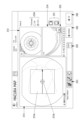
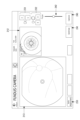
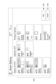
- FIG. 1 is an alignment screen in an embodiment, in which an anterior eye image is displayed as an observation image.
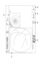
- 13 is an observation screen in the embodiment, in which macular multi is selected as the scan pattern.
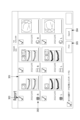
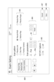
- 12 is a confirmation screen corresponding to FIG. 11.
- 1 is an observation screen in an embodiment, in which a macular map is selected as the scan pattern.
- 14 is a confirmation screen corresponding to FIG. 13.
- 1 is an observation screen in the embodiment, in which FC photography is selected.
- 16 is a confirmation screen corresponding to FIG. 15.
- 13 is a report output screen in the embodiment.
- 11 is a setting screen according to the embodiment.
- 11 is a setting screen according to the embodiment.
- 13 is a confirmation screen in a modified example, in which a wide-area map (retina map
- the ophthalmic imaging device has at least an imaging unit, a user interface, and a control unit (control means in the embodiment).
- the imaging unit projects and receives light onto the subject's eye.
- a unit that includes the imaging unit and is configured integrally with the imaging unit may be referred to as the device main body.
- the imaging unit has all or a part of the OCT optical system.
- the OCT optical system is capable of scanning the tissue of the test eye with multiple scan patterns.
- the OCT optical system may irradiate the test eye with measurement light and detect a spectral interference signal between the measurement light and the reference light.
- the OCT optical system has an optical scanner for scanning the measurement light with multiple scan patterns.
- the selection screen is displayed to allow the examiner to select an imaging operation.
- the control unit displays a plurality of examination selection buttons corresponding to preset examination patterns on the selection screen.
- the control unit accepts a selection operation for any of the examination selection buttons on the selection screen.
- the examination selection button is placed with identification information corresponding to each scan pattern, and further, in an examination pattern that combines multiple scan patterns, identification information corresponding to each scan pattern is placed on one examination selection button, so that an examiner can easily select a desired examination pattern via the examination selection button. Therefore, the screen configuration of this embodiment makes it easy to improve the efficiency of examinations in facilities, etc.
- the drive unit 8 moves the imaging unit 3 on the drive unit 8 in each of the XYZ directions relative to the subject's eye E.
- the drive unit 8 has an actuator for moving the imaging unit 3 in each movable direction, and is driven based on a control signal from the control unit 100.
- the face support unit 9 supports the subject's face.
- the face support unit 9 is fixed to the base 7.
- the face support unit 9 has a chin rest 9a.
- the chin rest 9a can move in the vertical direction, thereby adjusting the height of the subject's eye E according to the eye level of the device.
- the OCT optical system 31 has at least a detector, and the detector detects a spectral interference signal between the return light from the tissue due to the measurement light and the reference light.
- the control unit 50 performs a predetermined process on the spectral interference signal to generate an OCT image.
- the anterior-segment observation optical system 33 captures an image of the anterior segment of the subject's eye E and obtains an anterior-segment observation image.
- the anterior-segment observation optical system 33 uses infrared light as observation light.
- the anterior eye segment is illuminated, and a front image of the anterior eye segment is obtained as an anterior eye segment observation image based on the reflected light. It is used for alignment and tracking control.
- the control unit 50 is a processing device (processor) that controls each unit and performs calculation processing.
- the control unit 50 includes a CPU, RAM, ROM, etc.
- the control unit 50 is also assumed to perform image processing of various images obtained by the ophthalmic imaging apparatus 1. In other words, the control unit 50 also functions as an image processing unit.
- the control unit 50 is electrically connected to each part, such as the OCT optical system 31, the drive unit 8, the front imaging optical system 32, the anterior eye observation optical system 33, the face imaging camera 20, the memory unit 51, and the touch panel 100.
- the touch panel 100 serves as both a monitor and an operation input unit in the ophthalmologic imaging apparatus 1. Various images are displayed on the touch panel 100. In addition, a graphical user interface (GUI) is displayed on the touch panel 100, and operations on UI elements (widgets) by the examiner are accepted. Various touch operations are input via the touch panel 100.
- GUI graphical user interface
- the subject's identification information (ID, name, age, etc.) is newly registered or recalled (S1).
- the identification information is entered by reading a barcode containing the subject's identification information with a barcode reader connected to the device, or by directly entering the information via a keyboard.
- the identification information may be recalled by displaying a list of subjects and selecting the appropriate one from the list.
- the control unit 50 accepts an operation to select an examination pattern (S2).
- an examination selection screen shown in Fig. 4 to Fig. 6 is displayed.
- the contents of the imaging including the imaging method are determined based on the operation input via the examination selection screen.
- the test selection screen displays, as UI elements, an eye selection button 201, a mode switching tab 202, a test selection button 203, and a text box 204.
- the eye selection button 201 is a UI element for selecting the right eye, the left eye, or both eyes as the eye to be photographed.
- three buttons are provided, one for the right eye, one for the left eye, and one for both eyes.
- the subject eye E of the selected eye is photographed using a combo pattern (examination pattern) selected separately.
- both eyes are selected as the eyes to be photographed, one eye is photographed using a combo pattern selected separately, and then the other eye is photographed using the same combo pattern.
- the mode switching tab 202 is operated to switch the imaging mode.
- the OCT/FC mode see FIG. 4
- the anterior segment OCT mode see FIGS. 5 and 6
- the FC mode One of three imaging modes is selected: OCT/FC mode is selected when an OCT image of the fundus is to be captured.
- OCT/FC mode capturing a front image of the fundus (either a color fundus image, an infrared image, or an autofluorescence image) can also be combined with capturing an OCT image.
- the anterior segment OCT mode is selected when an OCT image of the anterior segment is to be captured.
- the FC mode is selected when a front image of the fundus is to be captured without combining OCT capture.
- a combo pattern including multiple imaging operations there may be a pattern that combines multiple imaging operations with different image types. For example, it may be a pattern in which an OCT image and a frontal fundus image are successively captured, or a pattern in which an intensity OCT image and a motion contrast image are successively captured.
- buttons 203 are arranged as test selection buttons 203 on one screen.
- Each button is associated with one combo pattern. Details will be described later, but the correspondence between buttons and combo patterns can be set and changed in advance via the setting screen described later.
- identification information corresponding to each of the photographing operations included in the combo pattern is arranged on each button.
- a graphic symbol is used as the identification information.
- multiple graphic symbols corresponding to each of the photographing operations are arranged.
- graphic symbols corresponding to each of the scan patterns in OCT photographing, macular multi and macular map are arranged, and further, a graphic symbol corresponding to photographing a frontal fundus image is arranged.
- the graphic symbols related to fundus OCT may indicate the pattern shape (scanning trajectory) in each scan pattern.
- the examiner can easily grasp the combination of scan patterns included in the combo pattern through the graphic symbols indicating the pattern shape of each scan pattern.
- the graphic symbol corresponding to photographing a frontal fundus image may be a schematic representation of the frontal fundus image.
- one or more graphic symbols corresponding to each photographing operation are arranged on each button, thereby indicating the content of the combo pattern corresponding to each button.
- the details of the combo pattern corresponding to the selected button are displayed in the text box 204 as text information.
- the shooting conditions (scanning conditions) for each shooting operation included in the combo pattern are shown for each shooting operation.
- an anterior eye adapter (not shown) is attached to the examination window of the imaging unit 3, enabling imaging of the anterior eye using OCT.
- an anterior eye adapter please refer to, for example, Japanese Patent Application Laid-Open No. 2011-147609 filed by the present applicant.
- a forehead rest for adjusting the working distance is attached to the face support unit 9 together with the anterior adapter.
- a message prompting the attachment of the forehead rest may be further displayed by a pop-up window 206 as shown in FIG. 6 . This effectively prevents forgetting to put on the forehead rest when taking anterior segment OCT images.
- the alignment screens shown in Figs. 7 and 10 display at least an observation image for alignment.
- the observation image can be either a face image 211 (see Fig. 7) acquired via the face photographing camera 20, or an anterior eye observation image 212 (see Fig. 10) acquired via the anterior eye observation optical system 33.
- the control unit 50 adjusts the position of the photographing unit 3 relative to the subject's eye E to a position where the subject's eye E can be photographed based on the observation image.
- the positions of the photographing unit 3 and the chin rest 9a of the face support unit 9 are adjusted from a state in which they are each a predetermined initial position to a state in which the optical axis of the photographing unit 3 coincides with the subject's eye E and further becomes the appropriate working distance.
- the alignment screens shown in Figures 7 and 10 further display a chin rest height adjustment button 231 and a front-to-back adjustment button 232.
- the chin rest height adjustment button 231 includes a pair of buttons corresponding to up and down.
- the control unit 50 moves the chin rest 9a in the face support unit 9 in the up and down direction.
- the front-to-back adjustment button 232 is operated to change the position of the imaging unit 3 in the front-to-back direction.
- the front-to-back adjustment button 232 includes a pair of buttons corresponding to front and back. When the front-to-back adjustment button 232 is operated, the control unit 50 moves the imaging unit 3 in the front-to-back direction.
- a face image 211 obtained via the face capturing camera 20 is displayed as an observation image.
- the control unit 50 analyzes the facial image 211 to detect the position of the subject's eye E.
- a line 211a indicating the reference height of the eye level is displayed at a fixed position in the observation image display area 211.
- the line 211a is shown by a dashed line in FIG. 7. If the position of the subject's eye E is far from the line 211a, the examiner operates the chin rest height adjustment button 231 to bring the subject's eye E closer to the line 211a, so that the subject's eye E (and the position of the subject's eye E) can be detected from the facial image 211.
- the position of the subject's eye E may be obtained as two-dimensional coordinates on the facial image 211.
- FIG. 8A is an example of the face image 211 when the detection is successful, and a mark 211c is superimposed on the position of the subject's eye E detected in the face image 211.
- the mark 211c may be superimposed on another position such as the eyebrow.
- the correct position of the subject's eye E is touched, and the detected position is corrected to the touched position or to the position of the subject's eye E detected in the peripheral area of the touched position.
- FIG. 8B is an example of the face image 211 when the detection fails.
- a mark 211d in a different form from when the detection is successful is superimposed on a predetermined position.
- a mark 211d in a broken line is superimposed on the line 211a.
- the detected position can be corrected by touching the correct position of the subject's eye E in the same manner as above.
- the control unit 50 moves the imaging unit 3 from its initial position to perform automatic alignment.
- the position of the imaging unit 3 is changed in a direction such that the optical axis of the imaging unit 3 (hereinafter referred to as the imaging optical axis) approaches the detected subject's eye E.
- the position of the imaging unit 3 is adjusted based on the position of the subject's eye E detected based on the facial image 211.
- the range in which the imaging unit 3 can move in the vertical direction is narrow compared to the angle of view of the face image 211. Even if the subject's eye E is detected outside the movable range, proper alignment cannot be performed by moving the imaging unit 3 alone.
- a mask 211b is superimposed on the display area of the observation image.
- the mask 211b is superimposed on the top and bottom of the display area.
- the mask 211b indicates that the area is outside the movable range of the photographing unit 3. More specifically, in this embodiment, the area on which the mask 211b is superimposed is outside the movable range of the photographing unit 3 when the photographing unit 3 is in a predetermined position (for example, the initial position). For example, as shown in FIG. 9, when the mask 211b is superimposed on the subject's eye E in the face image 211, the subject's eye E is located outside the movable range of the photographing unit 3.
- the subject's eye E since the position of the subject's eye E is below the movable range of the photographing unit 3, the subject's eye E can be positioned within the movable range of the photographing unit 3 by operating the chin rest height adjustment button 231 in the direction of raising the chin rest 9a. As a result, the photographing unit 3 can be moved to appropriately adjust the positional relationship between the photographing unit 3 and the subject's eye E. In this way, the examiner can easily know whether or not the height of the chin rest 9a needs to be adjusted by superimposing the mask 211b on the region of the face image 211 that is outside the movable range of the photographing unit 3. Furthermore, when the position of the subject's eye E on the face image 211 is outside the movable range of the photographing unit 3, the examiner can be appropriately prompted to operate the chin rest height adjustment button 231.
- the mask 211b when the image capturing unit 3 is in a predetermined position (e.g., the initial position), the mask 211b is superimposed outside the movable range of the image capturing unit 3, but this is not necessarily limited to this, and if the facial image 211 is displayed while the image capturing unit 3 is moving, the position of the mask 211b on the facial image may be changed depending on the position of the image capturing unit 3.
- a predetermined position e.g., the initial position
- the examiner judges whether the position of the subject's eye E detected from the face image 211 is outside the movable range of the photographing unit 3 by checking the observation image, and adjusts the height of the chin rest based on the examiner's operation.
- the control unit 50 judges whether the position of the subject's eye E detected from the face image 211 is outside the movable range of the photographing unit 3, and if the position of the subject's eye E is outside the movable range of the photographing unit 3, the height of the chin rest may be automatically adjusted, or guide information prompting the examiner to adjust the height of the chin rest 9a may be output via the user interface.
- the examination may proceed more smoothly if the area outside the movable range of the photographing unit 3 is shown on the observation image displayed on the face image, as in this embodiment, to prompt the examiner to intervene.
- the anterior eye observation image 212 is displayed as the observation image (see FIG. 10).
- the position of the photographing unit 3 is automatically moved with respect to the subject's eye E based on the anterior eye observation image 212.
- the photographing optical axis is further adjusted so as to coincide with the pupil center in the XY directions.
- an indicator 212a is superimposed on the anterior eye observation image 212. The state of the indicator 212a changes depending on the alignment state. This indicates the alignment state.
- the position of the photographing optical axis in the XY directions with respect to the subject's eye E can be adjusted based on a touch operation on the anterior eye observation image 212. For example, when an area in the direction in which the indicator 212a is to be moved is touched on the anterior eye observation image 212, the photographing unit 3 is moved according to that direction. Also, this is not necessarily limited to this, and the imaging unit 3 may be moved so that the center of the indicator 212a (imaging optical axis) moves to the touched position, or pupil detection may be performed centered on the touched position, and the imaging unit 3 may be moved so that the center of the indicator 212a (imaging optical axis) moves to the center of the detected pupil area.
- the photographing conditions are adjusted (S4).
- the alignment screen transitions to the observation screen.
- the button 203a shown in FIG. 4 is selected in the OCT/FC mode, the OCT image is photographed first using the macular multi-scan pattern.
- the observation screen displayed in this case is shown in FIG. 11.
- the configuration of the observation screen when photographing the OCT is described based on FIG. 11.
- the observation screen when photographing the OCT displays a fundus front image 213, a tomographic image 214, a detection condition controller, and a Capture button 245 on the screen.
- the fundus front image 213 and the tomographic image 214 displayed on the observation screen before the capture may be observation images acquired in real time.
- a graphic showing the scan pattern is displayed on the fundus front image 213. The graphic allows the examiner to grasp the photographing position of the OCT image.
- the imaging condition controller is operated to adjust the detection conditions of the OCT optical system 31 and the imaging conditions of the front imaging optical system 32.
- the detection conditions are any of various conditions related to the detection ability of ocular tissue, and specific examples include the optical path length difference (OPL), focus, detection sensitivity, polarization state, etc.
- the imaging conditions include, for example, focus, brightness (light amount, gain, or exposure time), contrast, etc.
- the shooting condition controllers are an Optimize button 241, a focus controller 242, and an OPL controller 243.
- the control unit 50 executes adjustment processing of the OCT optical system 31 and the front photographing optical system 32.
- the OPL, focus, and polarization of the OCT optical system 31 and the focus of the front photographing optical system 32 are adjusted to at least a predetermined state.
- the focus of the OCT optical system 31 and the front photographing optical system 32 may be adjusted based on the fundus observation image (fundus front image 213).
- a focus index may be projected onto the fundus, and the focus may be adjusted based on the focus index reflected in the fundus observation image.
- the result of the adjustment processing is reflected, for example, in the image quality and image position of the fundus front image 213 and the tomographic image 214. If the user checks the fundus front image 213 and the tomographic image 214 and determines that the adjustment has failed, the user can further operate the focus controller 242 and the OPL controller 243 to attempt manual adjustment.
- the focus controller 242 and the OPL controller 243 are operated to manually adjust the detection conditions and the imaging conditions, respectively.
- the focus controller 242 and the OPL controller 243 are sliders, and the position of the "knob" is moved based on a drag operation or the like.
- the imaging conditions and detection conditions are set according to the position of the knob.
- the slider of the focus controller 242 and/or the OPL controller 243 is operated according to the depth position of the layer region that is desired to be imaged with higher sensitivity.
- the anterior eye observation image 212, chin rest height adjustment button 231, front/rear adjustment button 232, and auto alignment button 233 are also displayed on the observation screen. This allows the alignment state to be confirmed even after transitioning to the observation screen. If the position of the subject's eye E has moved from the correct alignment position, alignment adjustment can be performed automatically or manually.
- the Capture button 245 accepts an operation that triggers the start of image capture.
- a scan for image capture is performed with a pre-determined scan pattern (in FIG. 11, a macular multi-scan pattern) (S5).
- the confirmation screen is a screen for confirming the image capturing results.
- the output contents of the report can be selected via the confirmation screen.
- the screen shown in FIG. 12 is displayed as a confirmation screen.
- the confirmation screen displays a tomographic image 214 obtained by the imaging scan, as well as an anterior eye observation image 212 and a frontal fundus image 213.
- the anterior eye observation image 212 and the frontal fundus image 213 displayed on the confirmation screen may be still images acquired simultaneously with the imaging scan.
- the alignment state during imaging and the appropriateness of the imaging conditions can be confirmed via the anterior eye observation image 212 and the frontal fundus image 213.
- the tomographic image 214 displayed on the confirmation screen can be switched to an image taken for another scan line.
- a scan line change button 251 is arranged on the confirmation screen. Each time the scan line change button 251 is operated, the tomographic image 214 displayed on the confirmation screen is switched to an image on another scan line in a predetermined order.
- the tomographic image 214 displayed on the confirmation screen is used as a representative image among the multiple scan lines.
- the representative image is an image output to a report from among the tomographic images taken for multiple scan lines. In the case of a macular multi scan pattern, one representative image is set for each scan line in the XY directions. However, the number of representative images and the direction of the scan lines can be determined appropriately for each scan pattern.
- the switch button 252 controls the tomographic image displayed on the screen between the X-direction scan line and the Y-direction scan line. Furthermore, by operating a button not shown, the tomographic image 214 is enlarged and displayed.
- the confirmation screen further includes an OK button 292 and a Retake button 293.
- the Retake button 293 is operated to retake an image.
- the Retake button 293 is operated, the most recent image capture result is discarded and the screen transitions to the observation screen. In this case, an image is captured using the same scan pattern as the most recent image capture.
- the shooting results are saved. Also, if the selected combo pattern includes a shooting action that has not yet been shot, the screen transitions to the observation screen. In this case, the scan pattern or the type of image to be shot is changed to the next one in the sequence.
- the progress (completion status) of the shooting operations included in the selected combo pattern is shown in a progress display box 253 (progress display area in the embodiment).
- a progress display box 253 progress display area in the embodiment.
- one or more symbols corresponding to the shooting operations included in the pre-selected combo pattern are arranged in a row in the progress display box 253.
- the symbol shown in the progress display box 253 is the same as the symbol displayed on the button selected by the examiner from among the examination selection buttons 203.
- a check mark is superimposed on the symbol corresponding to a completed shooting operation. This distinguishes between completed and incomplete shooting operations. Therefore, the examiner can easily grasp the progress of the shooting operations included in the combo pattern via the symbol.
- the screen proceeds to the next imaging operation.
- the OK button 292 is operated on the confirmation screen of FIG. 12
- the screen proceeds to the next imaging operation, imaging using a macular map.
- the control unit 50 transitions the screen from the confirmation screen shown in FIG. 6 to the observation screen shown in FIG. 13.
- a graphic superimposed on the frontal fundus image 213 represents a scan pattern of the macular map. The rest of the points are the same as in FIG. 11.
- the Capture button 245 is operated, imaging using a macular map is performed. As a result, a three-dimensional tomographic image centered on the macula is captured.
- the screen transitions to the confirmation screen shown in FIG. 14.
- an operation input for changing and setting the analysis region 213a in the three-dimensional tomographic image can be accepted via the confirmation screen shown in FIG. 14.
- the position of the analysis region 213a can be changed in the XY direction via the front image 213.
- the mark 213b indicating the center position of the analysis region 213a can be moved in response to an operation on the touch panel 100.
- the reference position of the analysis process using the normal eye database is displaced in response to the center position.
- the analysis region change button 254 is operated. As an example, in FIG.
- a button corresponding to the entire retina and a button corresponding to GCC are arranged as the analysis region change button 254.
- the area corresponding to the selected button is set as the analysis region 213a in the depth direction.
- the GCC is a complex layered region consisting of the retinal nerve fiber layer (RNFL), ganglion cell layer (GCL), and inner plexiform layer (IPL).
- the analysis area 213a changed or set via the confirmation screen is reflected in the analysis process for the imaging results displayed on the confirmation screen.
- an analysis process for tissue thickness is performed.
- a two-dimensional distribution of the measured values of tissue thickness and/or a two-dimensional distribution of the comparison results between the tissue thickness of a normal eye and the measured values is output as the result of the analysis process.
- the analysis process may be performed, for example, when a report for the imaging results is generated, or at other times.
- the content of the analysis process is not limited to the analysis process for layer thickness (details will be described later).
- the OK button 292 When the OK button 292 is operated on the confirmation screen in FIG. 14, the next shooting operation, which is to capture a frontal image of the fundus, is performed. At that time, the control unit 50 transitions the screen from the confirmation screen shown in FIG. 14 to the observation screen shown in FIG. 15. In the following explanation, it is assumed, as an example, that a color image is captured.
- the symbol displayed in the progress display box 253 on the confirmation screen is also used as a UI element for changing the next imaging operation.
- any one of the symbols displayed in the progress display area on the confirmation screen is arbitrarily selected based on operational input.
- the OK button 292 is operated, the selected imaging operation proceeds. This makes it possible to appropriately skip patterns for which imaging is no longer necessary in the examination, or to change the order of the examination.
- a left/right eye switching button 255 is disposed in the progress display box 253. When the left/right eye switching button 255 is operated, the imaging operation proceeds to the opposite eye. This makes it possible to switch between the left and right eyes at any stage and proceed with the examination.
- ⁇ Report output screen> An example of the report output screen is shown in Fig. 17.
- a report is generated for each photographing operation and each subject's eye E.
- three types of reports are output for each of the left and right eyes.
- a total of six reports 301 are generated and displayed on the report output screen.
- graphic symbols 302 corresponding to the shooting operation on which each report 301 is based are arranged around each report 301.
- the graphic symbols arranged around the report 301 are the same as the graphic symbols displayed on the button selected by the examiner from among the examination selection buttons 203, so that it is easy to understand from the graphic symbols which shooting operation each report shows.
- check boxes 303 are arranged corresponding to each report 301. Selecting a check box 303 places a check mark on the report. When a report has a check mark placed on it, operating the export button 304 or print button 305 outputs the report with the check mark placed on it. Also, by selecting the bulk selection check box 303, it is possible to place or remove check marks on all reports.
- the print button 305 causes a printer (not shown) to print out the report with the check mark.
- the combo patterns that can be selected by operating the test selection buttons 203 can be set and changed in advance.
- the screens used to set the combo pattern are shown in Figs. 18 and 19.
- the screen shown in Fig. 18 displays a list of test selection buttons 203 that can be selected in each mode.
- the screen transitions to that of FIG. 19, where the combo pattern corresponding to the button can be edited.
- the screen of FIG. 19 displays a combo list 406.
- a cell with "+" on the combo list 406 is selected, and one of the multiple scan patterns listed in the scan pattern selection unit 403 is selected, whereby a scan pattern included in the combo list 406 is added.
- the scan parameters e.g., scan length, scan pitch, and angle
- the scan parameters can be changed from the default values via the scan parameter setting unit 404.
- a combo pattern corresponding to each test selection button 203 is set.
- the symbol placed on each test selection button 203 is also changed according to the combo pattern.
- an operation input for changing and setting the analysis region in the three-dimensional tomographic image can be accepted via the confirmation screen.
- one analysis region centered on the macula is set, but multiple analysis regions may be set.
- map scanning is performed with the imaging range including the macula and the optic nerve
- an analysis map corresponding to each analysis region may be generated by analyzing three-dimensional OCT data in each of a first analysis region set around the macula and a second analysis region set around the optic nerve.
- an operation input for changing the reference position of the analysis in each of the first analysis region and the second analysis region may be input on the same confirmation screen. For example, as shown in FIG.
- an operation for moving the first mark 213c indicating the center position of the first analysis region and the second mark 213d indicating the center position of the second analysis region may be input, so that the reference position of each analysis region may be changed in the XY direction.
- the analysis region in the depth direction may also be able to be set separately between the first analysis region and the second analysis region.
- the analysis process is performed on the thickness of the tissue.
- the analysis process may be performed on the measurement values (actual measurements) based on the three-dimensional OCT data other than the thickness of the tissue, or may show the results of comparing the measurement values with the normal eye data.
- the measurement values based on the three-dimensional OCT data may relate to at least one of the thickness, density, and shape of the tissue.
- the analysis map may be a thickness map of the tissue of the subject eye E (specific examples include a fundus layer thickness map, a corneal thickness map, etc.), a density map (specific examples include a blood vessel density map, a cell density map, etc.), a curvature map (topography), a height map (elevation map), or a two-dimensional distribution of layer thickness information or a two-dimensional distribution of blood vessel information other than those listed here.
- the normal eye data may be statistical data on the normal eye for the measurement values (actual measurements) based on the three-dimensional OCT data.
- the comparison result may be information indicating the degree of deviation between the measurement value and the normal eye data, and may be expressed, for example, as a difference, a ratio (e.g., percentile), a standard deviation, or the like.
- the analysis map may also indicate a two-dimensional distribution of the change over time in the measurement value or the comparison result.
- the three-dimensional OCT data on which the analysis map is based indicates the reflection intensity in a three-dimensional area (a two-dimensional area in the XY directions plus the depth direction) of the subject's eye E, but is not necessarily limited to this and may be three-dimensional motion contrast data.
Landscapes
- Life Sciences & Earth Sciences (AREA)
- Health & Medical Sciences (AREA)
- Medical Informatics (AREA)
- Biophysics (AREA)
- Ophthalmology & Optometry (AREA)
- Engineering & Computer Science (AREA)
- Biomedical Technology (AREA)
- Heart & Thoracic Surgery (AREA)
- Physics & Mathematics (AREA)
- Molecular Biology (AREA)
- Surgery (AREA)
- Animal Behavior & Ethology (AREA)
- General Health & Medical Sciences (AREA)
- Public Health (AREA)
- Veterinary Medicine (AREA)
- Eye Examination Apparatus (AREA)
Abstract
撮影部と、ユーザーインターフェースと、予め設定された検査パターンと対応する複数の検査選択ボタンを選択画面に表示させ、選択画面においていずれかの検査選択ボタンに対する選択操作を受け付け、更に、選択操作を受け付けてから、観察画像が表示されると共に装置状態を調整するための第2画面に表示を遷移させ、第2画面の表示を経由した後に検査を実行する、制御手段と、を備え、検査選択ボタンには、スキャンパターンの種類を示す識別情報が配置されると共に、少なくともいずれかの検査選択ボタンは、2つ以上のスキャンパターンと対応する2種類以上の識別情報が配置されており、制御手段は、2種類以上の識別情報が配置された検査選択ボタンが選択されて検査が開始された場合には、その2種類以上の識別情報と対応する各々のスキャンパターンで被検眼を走査して各々のスキャンパターンに対応する被検眼のOCTデータを順次取得する。
Description
本開示は、眼科撮影装置に関する。
従来、眼科撮影装置として、光干渉断層計(Optical Coherence Tomography:OCT)、眼底カメラ、および、SLO等が、医療機関および検査施設(以下、まとめて「施設等」という)において広く利用されている。
OCTでは、OCT光学系を制御して被検眼の取得位置に対して測定光をスキャンすることによって、OCT画像として被検眼の断層画像が取得される。OCTでは、ラインスキャン、クロススキャン、マルチスキャン、ラジアルスキャン、ラスタースキャン、等の多様なスキャンパターンの中から、いずれかが、検査の度に選択される。検者がスキャンパターンを選択するために、グラフィカルユーザーインターフェース(GUI)が利用される。
例えば、特許文献1において、スキャンパターンを選択する際には、図21に示す画面500上のUI要素が操作される。図21に示した画面500には、スキャンパターンを選択するためのUI要素であるリスト510が、観察画像(前眼部観察画像520)、眼底正面画像530、および、OCT画像540と同時に表示されている。図21に示した画面500において、前眼部観察画像520は、手動または自動でのアライメント調整に利用される。また、画面500には、スキャンパラメータ設定用のUI要素550、光学系の手動調整用のUI要素560、自動調整用のオプティマイズボタン570、および、キャプチャーボタン580等が配置されている。つまり、スキャンパターンの選択からキャプチャーの開始までに必要とされる種々の操作を入力するためのUI要素が、同一の画面上に配置されている。
リスト510には、複数のスキャンパターンがリストアップされている。リスト510上における所望のスキャンパターンのテキスト510aが操作に基づいて選択されることで、いずれか1つのスキャンパターンが択一的に選択される。眼底正面画像530上には、選択されたスキャンパターンに応じたスキャンライン535が表示される。眼底正面画像530およびスキャンライン535によって、スキャンパターンと、走査位置とを確認することができる。OCT画像540は、スキャンライン535が示す走査位置においてリアルタイムに取得され、表示される。図21ではクロススキャンのスキャンパターンを構成する2つのOCT画像が並んで表示されている。スキャンライン535は、操作に応じて眼底正面画像530上で移動させることができ、これにより、走査位置が変更される。
上記先行技術の画面構成では、OCTの検査に不慣れな検者は、1つの画面中の構成が複雑であるために扱いが難しかった。また、医療機関および検査施設(以下、まとめて「施設等」という)の中には、いくつかの検査パターン(1つ以上のスキャンパターンの組み合わせ)だけを使用して、大半の被検者に対する検査を行う施設等も多い。そのような施設においては、予め定められたいくつかの検査パターンによる検査を、より単純な手順を用いて効率的に実施できることが望まれる。
本開示は、従来技術の問題点の少なくともいずれかに基づいてなされたものであり、検査効率が向上しやすい眼科撮影装置を提供することを技術課題とする。
本開示の第1態様に係る眼科撮影装置は、被検眼の組織上を複数のスキャンパターンで走査可能なOCT光学系の全部または一部を含む撮影部と、検者による操作入力を受け付けるユーザーインターフェースと、予め設定された検査パターンと対応する複数の検査選択ボタンを、選択画面に表示させ、前記選択画面においていずれかの前記検査選択ボタンに対する選択操作を受け付け、更に、前記選択操作を受け付けてから、観察画像が表示されると共に装置状態を調整するための第2画面に表示を遷移させ、前記第2画面の表示を経由した後に検査を実行する、制御手段と、を備え、前記検査選択ボタンには、前記スキャンパターンの種類を示す識別情報が配置されると共に、少なくともいずれかの前記検査選択ボタンは、2つ以上のスキャンパターンと対応する2種類以上の前記識別情報が配置されており、前記制御手段は、2種類以上の前記識別情報が配置された前記検査選択ボタンが選択されて検査が開始された場合には、その2種類以上の前記識別情報と対応する各々のスキャンパターンで被検眼を走査して各々のスキャンパターンに対応する被検眼のOCTデータを順次取得する。
[概要]
本開示に係る眼科撮影装置の実施形態を説明する。
本開示に係る眼科撮影装置の実施形態を説明する。
実施形態に係る眼科撮影装置は、撮影部と、ユーザーインターフェースと、制御部(実施形態における制御手段)と、を少なくとも有する。撮影部は、被検眼に対して投受光を行う。以下の説明では、撮影部を含み、撮影部と一体的に構成されたユニットを、便宜上、装置本体と称する場合がある。
撮影部は、OCT光学系の全部または一部を有する。例えば、少なくとも、OCT光学系の対物光学系および光スキャナが、撮影部に配置される。本実施形態において、OCT光学系は、被検眼の組織上を複数のスキャンパターンで走査可能である。OCT光学系は、被検眼に対して測定光を照射し、測定光と参照光とのスペクトル干渉信号を検出してもよい。OCT光学系は、複数のスキャンパターンで測定光を走査するための光スキャナを有する。
ユーザーインターフェースは、検者による操作入力を受け付ける。ユーザーインターフェースは、例えば、装置本体に取り付けられたタッチパネルディスプレイであって、表示部を兼用してもよい。タッチパネルディスプレイには、操作入力を受け付けるためのUI要素および撮影された画像が表示される。但し、必ずしもこれに限定されるものではなく、タッチパネルディスプレイ以外のユーザーインターフェースが採用されてもよい。
制御部は、眼科撮影装置における各種の制御(例えば、撮影制御、および、表示制御等)を司るプロセッサである。本実施形態において、制御部は、後述の選択画面および第2画面等、各種画面を表示部に表示させる。また、制御部は、撮影部を制御して、撮影動作を実行する。
選択画面は、撮影動作を検者に選択させるために表示される。制御部は、予め設定された検査パターンと対応する複数の検査選択ボタンを選択画面に表示させる。制御部は、選択画面においていずれかの検査選択ボタンに対する選択操作を受け付ける。
選択操作を受け付けてから、第2画面に表示が遷移される。第2画面は、被検眼の観察画像が表示されると共に装置状態を調整するための画面である。制御部は、第2画面に表示を遷移した段階で観察画像の表示を開始してもよい。本実施形態において、装置状態は、被検眼に対する撮影部のアライメント状態、および、OCT光学系の撮影条件のいずれかであってもよい。OCT光学系の撮影条件は、例えば、フォーカス、光路長差、偏光、および、分散、スキャン密度、の少なくともいずれかであってもよい。これらのうちいずれかの装置状態を調整するためのUI要素が第2画面に配置されていてもよい。追加的に、第2画面には、キャプチャーに関する操作を入力するためのUI要素が配置されていてもよい。
観察画像は、前眼部の観察画像であってもよいし、眼底の観察画像であってもよい。観察画像は、前眼部または眼底の正面画像であってもよい。また、観察画像は、選択されたスキャンパターンに含まれるいずれかのスキャンラインにおけるリアルタイムなOCT画像であっても良い。
眼科撮影装置は、例えば、被検眼の観察画像を取得するための観察光学系を有していても良い。また、アライメント調整のために、被検眼と撮影部との位置関係を調整するための駆動部、を更に有していても良い。第2画面が表示されている間、装置状態は、操作入力に応じて手動で調整可能であってもよいし、自動的に調整されてもよい。
制御部は、第2画面の表示を経由した後に検査を実行する。検査には、少なくとも、OCTデータ(OCT画像)のキャプチャーが含まれる。
このように、本実施形態では、検査選択ボタンが複数配置される選択画面と、観察画像が表示されると共に装置状態を調整するための第2画面(実施例における観察画面)とが、順番に表示される。これによって、いずれの被検者に対する検査においても、検査パターンを選択してから、装置状態を調整するように、手順が単純化される。また、選択画面は、観察画像が表示される画面(例えば、実施例における観察画面)とは別画面であることで、選択画面において識別情報が配置される複数の検査選択ボタンを、画面上でより大きなスペースを占めるように配置できるので、識別情報の視認性をより向上できる。
ここで、本実施形態では、選択画面において表示される検査選択ボタンには、スキャンパターンの種類を示す識別情報が配置される。少なくともいずれかの検査選択ボタンには、2つ以上のスキャンパターンと対応する2種類以上の識別情報が配置されていてもよい。制御部は、2種類以上の識別情報が配置された検査選択ボタンが選択されて検査が開始された場合には、その2種類以上の識別情報と対応する各々のスキャンパターンで被検眼を走査して各々のスキャンパターンに対応する被検眼のOCTデータを順次取得する。選択された検査パターンに基づく検査の途中では、選択画面が表示されることなく、順次動作が実行されてもよい。以上のように、複数のスキャンパターンを組み合わせた検査パターンを、検査選択ボタンを介して、検者が簡単に選択できる。検査選択ボタンには、各々のスキャンパターンと対応する識別情報が配置されており、更に、複数のスキャンパターンを組み合わせた検査パターンにおいては、それぞれのスキャンパターンと対応する識別情報が、1つの検査選択ボタンに配置されているので、検者が、検査選択ボタンを介して、所望の検査パターンを簡単に選択しやすい。従って、本実施形態の画面構成によって、施設等における検査の効率が向上しやすい。
本実施形態において、スキャンパターンの種類を示す識別情報は、図記号であっても良い。図記号は、例えば、それぞれのスキャンパターンにおけるスキャンの軌跡を、図によって表したものであってもよい。但し、識別情報としての図記号は、必ずしもこれに限定されるものではなく、スキャンパターンを特定できる図を含む任意の形式であり得る。識別情報として、追加的に又は代替的に、1~3語程度の文字が、記載されていてもよい。
ここで、図21に示す従来の装置では、スキャンパターンの選択からキャプチャーの開始までに必要とされる種々の操作を入力するためのUI要素が、同一の画面上に配置されており、選択したスキャンパターンは、即座に、眼底正面画像530上に重畳されるスキャンライン535によって確認することができた。
しかしながら、本実施形態では、検査選択ボタンが複数配置される選択画面と、観察画像が表示されると共に装置状態を調整するための第2画面(実施例における観察画面)とが、順番に表示される。選択画面において、検者が、スキャンパターンの選択を誤った場合は、再選択が必要となり、手戻りが生じてしまう。これに対し、識別情報に図記号が利用された場合、各々のスキャンパターンの内容を、より直感的に検者に把握させることができる。すなわち、検査パターンを選択する際に眼底正面画像と共に当該画像に重畳されるスキャンパターンを、必ずしも選択画面に表示させなくても、検査選択ボタンに配置される図記号によって、好適にスキャンパターンの内容を、検者に把握させることができる。その結果として、検査パターンの誤選択による手戻りが生じにくい。また、図記号を利用する方が、省スペースで各々のスキャンパターンを示すことが容易である。このため、特に、装置本体にタッチパネルディスプレイが取り付けられた装置等、画面サイズに制限がある装置において、図記号による表示が適している。
追加的に、眼科撮影装置は、OCT光学系以外の光学系を有していてもよい。例えば、正面画像撮影光学系を有していてもよい。正面画像撮影光学系は、被検眼の2次元正面画像を撮影する光学系である。この場合、検査パターンとして、2次元正面画像の撮影を含むパターンが選択可能となる。例えば、OCTによる1つまたは2つ以上のスキャンパターンと2次元正面画像の撮影とを組み合わせたパターン、2次元正面画像の撮影のみを行うパターン等が、検査パターンとして挙げられる。また、この場合、選択画面における検査選択ボタンには、OCTのスキャンパターン以外に、2次元正面画像の撮影を示す識別情報が配置されてもよい。
本実施形態において、検査パターンが選択されて選択画面から画面が遷移した後に、撮影動作の進捗状況が識別情報を用いて表示されてもよい。例えば、確認画面において、進捗状況が表示されてもよい。この場合、選択された検査パターンに含まれるそれぞれのスキャンパターン(およびOCT以外の撮影動作)と対応する識別情報が並べられると共に、撮影済みか否かを示す情報が、それぞれの識別情報と対応付けて表示されても良い。確認画面は、選択操作に応じたいずれかのスキャンパターンによって取得されたOCTデータが、画像として表示される。更に、確認画面には、再撮影を指示するための操作入力を受け付けるための再撮影用UI要素が配置されていてもよい。例えば、OCTデータの再撮影を行う場合、再撮影用UI要素が操作されると、確認画面上に表示されるOCTデータと同一のスキャンパターンによって撮影が行われてもよい。更に、確認画面には正常終了用のUI要素が配置されていてもよい。正常終了用のUI要素は、確認画面を介した確認の結果、所望のOCTデータが撮影された場合に、未撮影のスキャンパターンによる撮影を開始したり、検査パターンに基づく一連の撮影動作を完了したりするために操作されてもよい。識別情報を用いた進捗表示は、確認画面以外の画面において表示されても良い。例えば、観察画面において表示されても良い。
検査パターン毎のスキャンパターンの割り当て(換言すれば、選択画面に表示されるそれぞれの検査選択ボタンに対応するスキャンパターンの割り当て)は、設定画面を介して行われてもよい。特に、設定画面を選択画面と別画面とすることによって、選択画面を介して行う操作が複雑化しにくくなる。この場合、選択画面とは異なる画面である設定画面において、それぞれの検査選択ボタンに対応するスキャンパターンの割り当てが、操作入力に基づいて設定および変更可能であってもよい。選択画面を介して設定および変更された、それぞれの検査選択ボタンに対するスキャンパターンの割り当てに応じて、それぞれの検査選択ボタンに識別情報が配置される。設定画面では、それぞれの撮影方法を示すために識別情報が表示されてもよい。撮影画面と設定画面との間で、各々のスキャンパターンを示す識別情報が同一であることで、スキャンパターンの割り当てが容易となる。
本実施形態の眼科撮影装置は、更に、外部(例えば、施設内のシステム)と通信するための通信部(実施形態における通信手段)を有していてもよい。制御部は、検査選択ボタンのいずれかと対応する検査パターンのオーダーを受信した場合、選択画面では、オーダーと対応する検査選択ボタンが、選択操作に関わらず選択されてもよい。これにより、検者にオーダーを確認させつつ、オーダーに従った検査を容易に開始できる。
[実施例]
次に、実施形態に係る眼科撮影装置の一実施例について説明する。
次に、実施形態に係る眼科撮影装置の一実施例について説明する。
眼科撮影装置1は、被検眼EのOCT画像を撮影する。更に、眼底Erの2次元反射画像として、少なくともカラー眼底画像を撮影する。
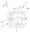
図1は、眼科撮影装置1の外観図である。本実施例において、眼科撮影装置1は、撮影部3、基台7、駆動部8、顔支持ユニット9、顔撮影カメラ20、制御部50、および、タッチパネル(以下、タッチパネルと称する)ディスプレイ100を有する。以下の説明では、便宜上、撮影部3が設置されたユニットを、装置本体と称する。本実施例では、基台7、駆動部8、顔支持ユニット9、顔撮影カメラ20、制御部50、および、タッチパネル100は、装置本体の一部である。但し、制御部50、および、タッチパネル100は、装置本体とは別体のユニットであってもよい。基台7、駆動部8、および、顔支持ユニット9は、装置本体において、適宜、省略可能である。
本実施例において、駆動部8は、撮影部3を、駆動部8上で被検眼Eに対してXYZの各方向に移動させる。駆動部8には、各可動方向に撮影部3を移動させるためのアクチュエータを有しており、制御部100からの制御信号に基づいて駆動される。顔支持ユニット9は、被検者の顔を支持する。顔支持ユニット9は基台7に固定されている。顔支持ユニット9は、顎台9aを有する。顎台9aは、上下方向に移動可能であり、これにより、装置のアイレベルに応じて被検眼Eの高さを調整する。
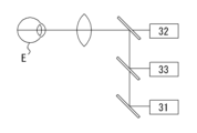
撮影部3は、図2で示す光学系を主に備える。図2に示すように、眼科撮影装置1は、OCT光学系31、正面撮影光学系32、および、前眼部観察光学系33を有する。本実施例において、それら3つの光学系は、図2に示すように、対物光学系が共用されており、ビームスプリッタ/コンバイナ(例えば、ハーフミラーおよびダイクロイックミラー等)によって同軸とされている。
顔撮影カメラ20は、被検者の顔を撮影する。制御部100は、撮影された顔画像から被検眼Eの位置を特定し、駆動部8を駆動制御することで、特定した被検眼Eの位置に対して撮影ユニット3を位置合わせする。
<OCT光学系>
OCT光学系31は、眼底ErのOCT画像の撮影に利用される。OCT画像は、2次元断層画像であってもよいし、3次元画像であってもよい。また、OCT画像として、強度OCT画像が取得されても良いし、モーションコントラスト画像が取得されても良い。
OCT光学系31は、眼底ErのOCT画像の撮影に利用される。OCT画像は、2次元断層画像であってもよいし、3次元画像であってもよい。また、OCT画像として、強度OCT画像が取得されても良いし、モーションコントラスト画像が取得されても良い。
本実施例において、OCT光学系31は、被検眼Eの組織上で、測定光を複数のスキャンパターンによって走査する。測定光を走査する光スキャナとして、例えば、2つのガルバノミラーを、OCT光学系31は有していても良い。ガルバノミラーに替えて、例えば、MEMSおよび音響光学素子等を用いることもできる。
OCT光学系31は、少なくとも検出器を有し、測定光による組織からの戻り光と、参照光と、のスペクトル干渉信号が、検出器によって検出される。スペクトル干渉信号に対して所定の処理が、制御部50によって行われることで、OCT画像が生成される。
OCT光学系31のさらなる詳細構成については、例えば、本出願人による「特開2011-147609公報」等を参照されたい。
<正面撮影光学系>
正面撮影光学系32は、眼底反射光に基づく眼底の2次元反射画像を撮影画像として取得する。正面撮影光学系は、走査型の光学系であってもよいし、非走査型の光学系であってもよい。走査型の光学系の一例として、スポットスキャンタイプの光学系と、ラインスキャンタイプの光学系とが挙げられる。スポットスキャンタイプの光学系では、眼底上でスポット状の撮影光が、二次元的にスキャンされる。ラインスキャンタイプの光学系では、ライン状の撮影光が一方向にスキャンされる(詳細は、第2実施形態において後述する)。また、非走査型の光学系の一例としては、一般的な眼底カメラの光学系等が挙げられる。正面撮影光学系32のさらなる詳細構成については、例えば、本出願人による「特開2019-118721号公報」「特開2019-141737号公報」および「特開2008-6105号公報」等を参照されたい。
正面撮影光学系32は、眼底反射光に基づく眼底の2次元反射画像を撮影画像として取得する。正面撮影光学系は、走査型の光学系であってもよいし、非走査型の光学系であってもよい。走査型の光学系の一例として、スポットスキャンタイプの光学系と、ラインスキャンタイプの光学系とが挙げられる。スポットスキャンタイプの光学系では、眼底上でスポット状の撮影光が、二次元的にスキャンされる。ラインスキャンタイプの光学系では、ライン状の撮影光が一方向にスキャンされる(詳細は、第2実施形態において後述する)。また、非走査型の光学系の一例としては、一般的な眼底カメラの光学系等が挙げられる。正面撮影光学系32のさらなる詳細構成については、例えば、本出願人による「特開2019-118721号公報」「特開2019-141737号公報」および「特開2008-6105号公報」等を参照されたい。
<前眼部観察光学系>
前眼部観察光学系33は、被検眼Eの前眼部を撮像し、前眼部観察画像として取得する。本実施例において、前眼部観察光学系33は、観察光として赤外光で前眼部を照明すると共に、反射光に基づいて前眼部の正面画像が前眼部観察画像として取得される。前眼部の観察画像は、眼底撮影時における被検眼Eに対する撮影ユニット3のアライメントおよび追従制御(トラッキング)に利用される。
前眼部観察光学系33は、被検眼Eの前眼部を撮像し、前眼部観察画像として取得する。本実施例において、前眼部観察光学系33は、観察光として赤外光で前眼部を照明すると共に、反射光に基づいて前眼部の正面画像が前眼部観察画像として取得される。前眼部の観察画像は、眼底撮影時における被検眼Eに対する撮影ユニット3のアライメントおよび追従制御(トラッキング)に利用される。
<制御部>
制御部50は、各部の制御処理と、演算処理とを行う処理装置(プロセッサ)である。制御部50は、CPU、RAM、ROM、等を備える。また、制御部50は、便宜上、眼科撮影装置1にて得られた各種画像の画像処理を行うものとする。換言すれば、制御部50が画像処理部を兼用する。
制御部50は、各部の制御処理と、演算処理とを行う処理装置(プロセッサ)である。制御部50は、CPU、RAM、ROM、等を備える。また、制御部50は、便宜上、眼科撮影装置1にて得られた各種画像の画像処理を行うものとする。換言すれば、制御部50が画像処理部を兼用する。
制御部50は、OCT光学系31、駆動部8、正面撮影光学系32、前眼部観察光学系33、顔撮影カメラ20、記憶部51、タッチパネル100等の各部と、電気的に接続されている。
記憶部51は、電源の供給が遮断されても記憶内容を保持できる、非一過性の記憶媒体であってもよい。例えば、記憶部51には、各種の制御プログラム、固定データ、等が格納される。また、例えば、記憶部51には、眼科撮影装置1による撮影画像が記憶される。撮影画像は、外部の記憶装置(例えば、制御部50にLANおよびWANで接続された記憶装置)へ転送されてもよい。
<タッチパネルディスプレイ>
タッチパネル100は、眼科撮影装置1におけるモニタおよび操作入力部を兼用する。タッチパネル100には、各種画像が表示される。また、グラフィカルユーザーインターフェース(GUI)が表示され、UI要素(ウィジェット)に対する検者の操作を受け付ける。タッチパネル100を介して各種のタッチ操作が入力される。
タッチパネル100は、眼科撮影装置1におけるモニタおよび操作入力部を兼用する。タッチパネル100には、各種画像が表示される。また、グラフィカルユーザーインターフェース(GUI)が表示され、UI要素(ウィジェット)に対する検者の操作を受け付ける。タッチパネル100を介して各種のタッチ操作が入力される。
<詳細な画面構成>
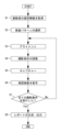
OCT装置1において撮影に用いるグラフィカルユーザーインターフェース(GUI)を、本実施例における眼科撮影装置1の動作の流れに沿って説明する。図3は、動作の流れを表したフローチャートを示す。また、動作の各タイミングにおいて、タッチパネル100に表示される画面を、図4~図20に示す。
OCT装置1において撮影に用いるグラフィカルユーザーインターフェース(GUI)を、本実施例における眼科撮影装置1の動作の流れに沿って説明する。図3は、動作の流れを表したフローチャートを示す。また、動作の各タイミングにおいて、タッチパネル100に表示される画面を、図4~図20に示す。
まず、被検者の識別情報(ID、氏名、年齢等)の新規登録または呼出しを行う(S1)。例えば、被検者の識別情報が記述されたバーコードを装置に接続されたバーコードリーダーで読み取ったり、キーボードを介した直接入力したりすることで、識別情報が入力される。すでに識別情報が登録済みの被検者を撮影する場合は、被検者のリストを表示して当該リストの中から該当するいずれかを選択することで、識別情報を呼び出してもよい。
<検査パターン選択>
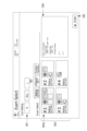
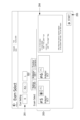
次に、制御部50は、検査パターンの選択操作を受け付ける(S2)。この場合、図4~図6に示す、検査選択画面が表示される。検査選択画面を介した操作入力に基づいて、撮影方法を含む撮影の内容が決定される。
次に、制御部50は、検査パターンの選択操作を受け付ける(S2)。この場合、図4~図6に示す、検査選択画面が表示される。検査選択画面を介した操作入力に基づいて、撮影方法を含む撮影の内容が決定される。
図4~図6に示すように、検査選択画面には、UI要素として、眼選択ボタン201と、モード切替タブ202と、検査選択ボタン203と、テキストボックス204と、が表示される。
眼選択ボタン201は、撮影対象眼として、右眼、左眼、および、両眼のいずれかを選択するためのUI要素である。図4~図6の例では、右眼、左眼、および、両眼のそれぞれと対応する3つのボタンが設けられている。撮影対象眼として右眼または左眼が選択された場合は、別途選択されるコンボパターン(検査パターン)を用いて、選択された側の被検眼Eが撮影される。撮影対象眼として両眼が選択された場合は、別途選択されるコンボパターンを用いて片眼が撮影された後に、同様のコンボパターンを用いて反対眼が撮影される。
モード切替タブ202は、撮影モードを切替えるために操作される。本実施例では、OCT/FCモード(図4参照)、前眼部OCTモード(図5,図6参照)、FCモード(
図示なし)、の3つの撮影モードの中からいずれかが選択される。OCT/FCモードは
、眼底のOCT画像を撮影する場合に選択される。OCT/FCモードでは、眼底の正面
画像(カラー眼底画像、赤外画像、自発蛍光画像のいずれか)の撮影を、OCT画像の撮影と組み合わせて行うこともできる。前眼部OCTモードは、前眼部のOCT画像を撮影する場合に選択される。FCモードは、OCT撮影を組み合わせることなく、眼底正面画像を撮影する場合に選択される。
図示なし)、の3つの撮影モードの中からいずれかが選択される。OCT/FCモードは
、眼底のOCT画像を撮影する場合に選択される。OCT/FCモードでは、眼底の正面
画像(カラー眼底画像、赤外画像、自発蛍光画像のいずれか)の撮影を、OCT画像の撮影と組み合わせて行うこともできる。前眼部OCTモードは、前眼部のOCT画像を撮影する場合に選択される。FCモードは、OCT撮影を組み合わせることなく、眼底正面画像を撮影する場合に選択される。
検査選択ボタン203は、コンボパターンを選択するためのUI要素である。各々のコンボパターンには、1つ以上の撮影動作が含まれる。複数の撮影動作を含むコンボパターンは、1つの被検眼Eに対して複数の撮影動作を続けて行うために用意されている。例えば、複数の撮影動作を含むコンボパターンの例として、複数のスキャンパターンを組み合わせたパターンがあり得る。各々のスキャンパターンによって、組織上においてOCT画像が取得される位置、および、OCT画像が取得される数が特定される。スキャンパターンの種別としては、例えば、ラインスキャン、クロススキャン、マルチスキャン、ラジアルスキャン、および、ラスタースキャン(マップスキャンともいう)等が挙げられる。更に、種別毎に、組織上の位置およびスキャン長が互いに異なる複数のスキャンパターンが用意されていてもよい。また、例えば、複数の撮影動作を含むコンボパターンの例として、画像種別が異なる複数の撮影動作を組み合わせたパターンがあり得る。例えば、OCT画像と眼底正面画像とを続けて撮影するパターンであってもよいし、強度OCT画像とモーションコントラスト画像とを続けて撮影するパターンであってもよい。
本実施例では、同一画面につき、最大4つのボタンが、検査選択ボタン203として配置される。各ボタンに1つのコンボパターンが対応づけられている。詳細は後述するが、ボタンとコンボパターンとの対応関係は、後述の設定画面を介して、あらかじめ設定および変更可能である。
図4~図6に示すように、各ボタンには、コンボパターンに含まれる各々の撮影動作と対応する識別情報が配置される。本実施例では、識別情報として、図記号が利用される。複数の撮影動作を含むコンボパターンの場合、各々の撮影動作と対応する複数の図記号が配置される。例えば、図4に示すボタン203aには、OCT撮影におけるスキャンパターンである、黄斑マルチ、および、黄斑マップ、の各々と対応する図記号がそれぞれ配置されており、更に、眼底正面画像の撮影と対応する図記号が配置されている。例えば、図4に示すように、眼底OCTに関する図記号は、各々のスキャンパターンにおけるパターン形状(スキャン軌跡)を示すものであってもよい。検者は、コンボパターンに含まれるスキャンパターンの組み合わせを、各々のスキャンパターンのパターン形状を示す図記号を介して、容易に把握できる。眼底正面画像の撮影と対応する図記号は、眼底正面画像を模式的に示すものであってもよい。このように、本実施例では、各々のボタンに、各々の撮影動作と対応する図記号が1つ以上配置されていることで、各々のボタンと対応するコンボパターンの内容が示されている。
検査選択ボタン203のうちいずれかが選択された場合、テキストボックス204には、選択されたボタンと対応するコンボパターンの詳細が、テキスト情報によって表示される。すなわち、コンボパターンに含まれる各々の撮影動作についての撮影条件(スキャン条件)が、撮影動作毎に示される。
検査選択ボタン203のうちいずれかが選択された状態で、スタートボタン205を操作することによって、検査パターンが決定されると共に、検査選択画面から次の画面(本実施例では、アライメント画面)へと遷移する。
本実施例では、図4~図6に示すように、モード切替タブ202の操作に基づいて撮影モードが切替わると、撮影モードと連動して、検査選択ボタン203も変更される。例えば、図5に示すように、前眼部OCTモードでは、検査選択ボタン203として、前眼部OCTにおけるスキャンパターンを示す図記号が配置されたボタンが表示される。
また、本実施例では、図示なき前眼部アダプタが、撮影部3の検査窓に装着されることによって、前眼部OCTの撮影が可能となる。前眼部アダプタの詳細については、例えば、本出願人による「特開2011-147609号公報」等を参照されたい。
そこで、前眼部OCTのスキャンパターンを含むコンボパターンに対応するボタンが選択された場合、テキストボックス204には、前眼部アダプタの装着を要求する旨のメッセージが表示される。この場合において、例えば、制御部50は、検査選択画面の表示と並行して、制御部50は、前眼部アダプタの着脱を検出してもよい。制御部50は、前眼部アダプタが装着されていない場合は、選択中の検査選択ボタン203が前眼部OCTのスキャンパターンを含むコンボパターンに対応するものであっても、スタートボタン205に対する操作を無効化してもよい。また、前眼部アダプタの装着を要求する旨のメッセージは、スタートボタン205に対する操作が入力された段階であって、前眼部アダプタの装着が検出されなかった場合に、出力されてもよい。また、本実施例において、前眼部OCTを撮影する際には、前眼部アダプタと共に、作動距離調整用の額当てが、顔支持ユニット9に装着される。前眼部アダプタの装着が検出されたことをトリガとして、図6に示すように、ポップアップウィンドウ206によって、額当ての装着を促すメッセージを、更に表示しても良い。これにより、前眼部OCTを撮影する際に、額当てを付け忘れてしまうことを好適に抑制できる。
<アライメント>
検査選択画面において検査選択ボタン203が選択され、更に、スタートボタン205が操作されることで、アライメント画面に遷移する。アライメント画面を、図7,図10に示す。この状態で、アライメント調整が実行される(S3)。
検査選択画面において検査選択ボタン203が選択され、更に、スタートボタン205が操作されることで、アライメント画面に遷移する。アライメント画面を、図7,図10に示す。この状態で、アライメント調整が実行される(S3)。
図7,図10に示すアライメント画面には、少なくとも、アライメント用の観察画像が表示される。観察画像は、顔撮影カメラ20を介して取得される顔画像211(図7参照)、および、前眼部観察光学系33を介して取得される前眼部観察画像212(図10参照)のいずれかであり得る。アライメント画面の表示と並行して、制御部50は、観察画像に基づいて被検眼Eが撮影可能な位置へと、撮影部3の位置を被検眼Eに対して調整する。本実施例では、撮影部3の位置、および、顔支持ユニット9における顎台9aの位置、がそれぞれ所定の初期位置である状態から、撮影部3の光軸が被検眼Eに一致し更に適正作動距離となる状態まで調整される。
図7,図10に示すアライメント画面には、顎台高さ調整ボタン231と、前後調整ボタン232と、が更に表示される。顎台高さ調整ボタン231は上下に対応する一対のボタンを含む。顎台高さ調整ボタン231が操作されることによって、制御部50は、顔支持ユニット9における顎台9aを上下方向に移動させる。前後調整ボタン232は、撮影部3の位置を、前後方向に変更するために操作される。前後調整ボタン232は、前後に対応する一対のボタンを含む。前後調整ボタン232が操作されることによって、制御部50は、撮影部3を前後方向に移動させる。
本実施例では、まず、図7に示すように、顔撮影カメラ20を介して得られる顔画像211が、観察画像として表示される。
制御部50は、顔画像211を解析して、被検眼Eの位置を検出する。このとき、観察画像表示領域211には、アイレベルの基準高さを示すライン211aが一定の位置に表示される。ライン211aは、図7において破線で示されている。被検眼Eの位置がライン211aから離れている場合は、検者が顎台高さ調整ボタン231を操作して、被検眼Eをライン211aに近づけることで、顔画像211から被検眼E(および被検眼Eの位置)が検出されるようになる。被検眼Eの位置は、顔画像211上の二次元の座標として取得されてもよい。
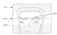
顔画像211に対して被検眼Eの検出が行われると、検出結果が表示される。本実施例では、図8Aは、検出に成功した場合における、顔画像211の例であり、顔画像211において検出された被検眼Eの位置にマーク211cが重畳される。但し、誤検出により、眉等の他の位置にマーク211cが重畳される場合がある。この場合、正しい被検眼Eの位置を、タッチすることによって、タッチした位置に、又は、タッチした位置の周辺領域において検出される被検眼Eの位置に、検出位置が修正される。図8Bは、検出に失敗した場合における、顔画像211の例である。検出に失敗すると、予め定められた位置に、成功時とは異なる態様のマーク211dが重畳される。図8Bでは、一例として、ライ
ン211a上に、破線によるマーク211dが重畳されている。この場合も、上記と同様
に、正しい被検眼Eの位置を、タッチすることによって、検出位置を修正できる。
ン211a上に、破線によるマーク211dが重畳されている。この場合も、上記と同様
に、正しい被検眼Eの位置を、タッチすることによって、検出位置を修正できる。
顔画像211に基づいて被検眼Eの位置が検出される状態となったら、制御部50は、撮影部3を初期位置から移動させて自動アライメントを実行する。例えば、撮影部3の光軸(以下、撮影光軸と称する)が、検出された被検眼Eに近づく方向に、撮影部3の位置を変更する。つまり、顔画像211に基づいて検出された被検眼Eの位置に基づいて、撮影部3の位置が調整される。
ところで、本実施例では、撮影部3が上下方向に関して移動可能な範囲は、顔画像211の画角に対して狭い。移動可能な範囲外において、被検眼Eが検出されたとしても、撮影部3の移動だけでアライメントを適切に行うことはできない。
これに対し、本実施例では、観察画像として顔画像211が表示される場合、観察画像の表示領域に、マスク211bが重畳される。本実施例において、マスク211bは、表示領域の上下それぞれに重畳される。マスク211bは、撮影部3の可動範囲外であることを示す。より詳細には、本実施例では、マスク211bが重畳された領域は、撮影部3が所定の位置(例えば、初期位置)にあるときにおける、撮影部3の可動範囲外である。例えば、図9に示すように、顔画像211において、被検眼Eにマスク211bが重なっている場合、被検眼Eは撮影部3の可動範囲外に位置している。図9の場合、被検眼Eの位置が、撮影部3の可動範囲に対して下方であるため、顎台9aを上昇させる方向に顎台
高さ調整ボタン231を操作することによって、撮影部3の可動範囲内に被検眼Eを位置させることができる。その結果、撮影部3を移動させて、撮影部3と被検眼Eとの位置関係を適切に調整できるようになる。このように、顔画像211において撮影部3の可動範囲外となる領域に、マスク211bが重畳されていることによって、顎台9aの高さ調整が必要であるか否かを、検者が容易に把握できる。また、顔画像211上の被検眼Eの位置が撮影部3の可動範囲外に存在する場合に、顎台高さ調整ボタン231の操作を、検者に対して適切に促すことができる。
高さ調整ボタン231を操作することによって、撮影部3の可動範囲内に被検眼Eを位置させることができる。その結果、撮影部3を移動させて、撮影部3と被検眼Eとの位置関係を適切に調整できるようになる。このように、顔画像211において撮影部3の可動範囲外となる領域に、マスク211bが重畳されていることによって、顎台9aの高さ調整が必要であるか否かを、検者が容易に把握できる。また、顔画像211上の被検眼Eの位置が撮影部3の可動範囲外に存在する場合に、顎台高さ調整ボタン231の操作を、検者に対して適切に促すことができる。
上記の通り、本実施例では、撮影部3が所定の位置(例えば、初期位置)にあるときの、撮影部3の可動範囲外に、マスク211bが重畳されるが、必ずしもこれに限定されるものではなく、撮影部3の移動中に顔画像211が表示される場合は、顔画像上のマスク211bの位置が、撮影部3の位置に応じて変更されても良い。
本実施例では、撮影部3の可動範囲外であるか否かを、観察画像を確認することによって、検者自らが判断し、検者の操作に基づいて顎台の高さを調整する場合について説明したが、必ずしもこれに限定されるものでは無い。例えば、顔画像211から検出される被検眼Eの位置が、撮影部3の可動範囲外であるか否かを、制御部50が判定し、更に、被検眼Eの位置が、撮影部3の可動範囲外である場合に、顎台の高さを自動で調整する、または、顎台9aの高さの調整操作を促すガイド情報を、ユーザーインターフェースを介して出力してもよい。但し、顔画像211から被検眼Eを検出する際に、誤検出してしまったり、検出に失敗してしまったりする場合があり得る。これに対し、本実施例のように、撮影部3の可動範囲外の領域を顔画像上が表示される観察画像上で示して、検者に介入を促すほうが、検査がスムーズに進行しやすい場合がある。
遷移ボタン291の操作に基づいて、前眼部観察画像212が、観察画像として表示されるようになる(図10参照)。本実施例では、オートアライメントボタン233が選択されていると、前眼部観察画像212に基づいて、被検眼Eに対して撮影部3の位置が自動的に移動される。本実施例では、アライメント指標を投影して、XYZの各方向の位置関係を調整した後、更に、XY方向に関しては、撮影光軸が瞳孔中心と一致するように調整される。本実施例において、前眼部観察画像212には、インジケーター212aが重畳表示される。インジケーター212aの態様は、アライメント状態に応じて変化する。これによって、アライメント状態が示される。また、本実施例では、前眼部観察画像212に対するタッチ操作に基づいて、被検眼Eに対する撮影光軸のXY方向に関する位置を調整できる。例えば、前眼部観察画像212上で、インジケーター212aを移動させたい方向上の領域をタッチすると、その方向に応じて撮影部3が移動される。また、必ずしもこれに限定されるものではなく、タッチした位置にインジケーター212aの中心(撮影光軸)が移動されるよう、撮影部3が移動されてもよいし、タッチした位置を中心に瞳孔検出を行い、検出された瞳孔領域の中心にインジケーター212aの中心(撮影光軸)が移動されるように、撮影部3が移動されてもよい。
以下では、特に断りが無い限り、検査選択画面において、OCT/FCモードで図4に
示すボタン203aが選択された場合を、一例として説明する。よって、黄斑マルチ、および、黄斑マップ、によってOCT画像が撮影され、更に、眼底正面画像が撮影される場合の動作を示す。
示すボタン203aが選択された場合を、一例として説明する。よって、黄斑マルチ、および、黄斑マップ、によってOCT画像が撮影され、更に、眼底正面画像が撮影される場合の動作を示す。
<撮影条件の調整>
アライメントの完了後、撮影条件が調整される(S4)。本実施例では、アライメントの完了後、アライメント画面から観察画面へと遷移する。OCT/FCモードで図4に示
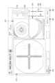
すボタン203aが選択された場合は、黄斑マルチのスキャンパターンによるOCT画像の撮影が、最初に行われる。この場合に表示される観察画面を、図11に示す。本実施例では、図11に基づいて、OCTを撮影する際の観察画面の構成を説明する。図11に示すように、本実施例において、OCTを撮影する際の観察画面には、眼底正面画像213、断層画像214、検出条件コントローラー、および、Captureボタン245が、画面上に表示される。キャプチャーの実行以前に観察画面に表示される眼底正面画像213、および、断層画像214は、リアルタイムに取得される観察画像であってもよい。また、眼底正面画像213上には、スキャンパターンを示すグラフィックが表示される。当該グラフィックによって、検者は、OCT画像の撮影位置を把握できる。
アライメントの完了後、撮影条件が調整される(S4)。本実施例では、アライメントの完了後、アライメント画面から観察画面へと遷移する。OCT/FCモードで図4に示
すボタン203aが選択された場合は、黄斑マルチのスキャンパターンによるOCT画像の撮影が、最初に行われる。この場合に表示される観察画面を、図11に示す。本実施例では、図11に基づいて、OCTを撮影する際の観察画面の構成を説明する。図11に示すように、本実施例において、OCTを撮影する際の観察画面には、眼底正面画像213、断層画像214、検出条件コントローラー、および、Captureボタン245が、画面上に表示される。キャプチャーの実行以前に観察画面に表示される眼底正面画像213、および、断層画像214は、リアルタイムに取得される観察画像であってもよい。また、眼底正面画像213上には、スキャンパターンを示すグラフィックが表示される。当該グラフィックによって、検者は、OCT画像の撮影位置を把握できる。
撮影条件コントローラーは、OCT光学系31の検出条件、および、正面撮影光学系32の撮影条件を調整するために操作される。検出条件は、眼組織の検出能力に関わる種々の条件のいずれかであって、具体的には、光路長差(以下、OPL)、フォーカス、検出感度、偏光状態、等が挙げられる。撮影条件は、例えば、フォーカス、明るさ(光量、ゲイン、露光時間のいずれか)、コントラスト、等が挙げられる。
本実施例では、撮影条件コントローラーとして、Optimizeボタン241、フォーカスコントローラ242、および、OPLコントローラー243、が配置されている。
Optimizeボタン241が操作された場合、制御部50は、OCT光学系31および正面撮影光学系32の調整処理を実行する。本実施例では、一例として、OCT光学系31におけるOPL、フォーカス、および、偏光の各々と、正面撮影光学系32のフォーカスと、が少なくとも所定の状態に調整される。OCT光学系31および正面撮影光学系32のフォーカスは、眼底観察画像(眼底正面画像213)に基づいて調整されてもよい。この場合、眼底に対してフォーカス指標が投影され、眼底観察画像に映り込むフォーカス指標に基づいてフォーカスが調整されても良い。調整処理の結果は、例えば、眼底正面画像213、および、断層画像214の画質や像の位置等に反映される。ユーザーは、眼底正面画像213、および、断層画像214を確認して、調整に失敗していると判断した場合、更に、フォーカスコントローラ242およびOPLコントローラー243を操作して、マニュアルによる調整を試みることができる。
フォーカスコントローラ242およびOPLコントローラー243は、それぞれ、検出条件および撮影条件を手動で調整するために操作される。本実施例において、フォーカスコントローラ242およびOPLコントローラー243は、スライダーであって“つまみ”の位置が、ドラッグ操作等に基づいて移動される。つまみの位置に応じて、それぞれの撮影条件および検出条件が設定される。例えば、より高感度に撮影したい層領域の深さ位置に応じて、フォーカスコントローラ242および/またはOPLコントローラー243のスライダーが操作される。
追加的に、本実施例では、前眼部観察画像212、顎台高さ調整ボタン231、前後調整ボタン232、オートアライメントボタン233も、観察画面に表示される。これにより、観察画面へ遷移した後でも、アライメント状態を確認できる。被検眼Eの位置が適正アライメント位置から動いてしまった場合には、自動またはマニュアルでアライメント調整が可能である。
<キャプチャー>
Captureボタン245は、撮影(キャプチャー)を開始するトリガとなる操作を受け付ける。Captureボタン245が操作されることによって、事前に決定されているスキャンパターン(図11においては、黄斑マルチのスキャンパターン)で、撮影用のスキャンが実行される(S5)。
Captureボタン245は、撮影(キャプチャー)を開始するトリガとなる操作を受け付ける。Captureボタン245が操作されることによって、事前に決定されているスキャンパターン(図11においては、黄斑マルチのスキャンパターン)で、撮影用のスキャンが実行される(S5)。
<確認画面の表示>
撮影が完了すると、確認画面に遷移する。確認画面は、撮影結果を確認するための画面である。また、本実施例では、レポートの出力内容を、確認画面を介して選択できる。
撮影が完了すると、確認画面に遷移する。確認画面は、撮影結果を確認するための画面である。また、本実施例では、レポートの出力内容を、確認画面を介して選択できる。
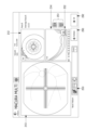
例えば、黄斑マルチのスキャンパターンによる撮影が完了した場合、図12に示す画面が、確認画面として表示される。本実施例では、確認画面には、撮影用のスキャンによって得られた断層画像214のほか、前眼部観察画像212、および、眼底正面画像213が表示される。確認画面に表示される前眼部観察画像212、および、眼底正面画像213は、撮影用のスキャンと同時に取得された静止画であってもよい。前眼部観察画像212、および、眼底正面画像213を介して、撮影の際のアライメント状態、および、撮影条件の適否を確認することができる。
複数のスキャンラインに関して断層画像214が撮影されている場合、確認画面に表示される断層画像214を、別のスキャンラインに関して撮影された画像に切り替え可能である。本実施例では、確認画面に、スキャンライン変更ボタン251が配置されている。スキャンライン変更ボタン251が操作される毎に、確認画面に表示される断層画像214が、別のスキャンラインにおける画像へと所定の順序に従って切り替わる。確認画面に表示される断層画像214が、複数のスキャンラインの中での代表画像として利用される。代表画像は、複数のスキャンラインに関して撮影された断層画像のうち、レポートに出力される画像である。黄斑マルチのスキャンパターンの場合、XY各方向のスキャンラインにつき、1枚ずつの代表画像が設定される。但し、代表画像の数やスキャンラインの方向は、スキャンパターン毎に適宜定められ得る。
また、スイッチボタン252が操作されることによって、X方向のスキャンラインとY方向のスキャンラインとの間で、画面上に表示される断層画像が切り換えられる。また、図示なきボタンが操作されることによって、断層画像214が拡大表示される。
確認画面には、OKボタン292と、Retakeボタン293と、が更に配置されている。Retakeボタン293は、再撮影を行うために操作される。本実施例では、Retakeボタン293が操作された場合、直近の撮影結果を破棄し、観察画面に遷移する。この場合において、直近の撮影と同一のスキャンパターンで撮影が行われる。
OKボタン292が操作された場合、撮影結果が保存される。また、選択されたコンボパターンに、未撮影の撮影動作が含まれている場合、観察画面に遷移する。この場合、スキャンパターンまたは撮影する画像種別が、次の順序のものに変更される。
選択されたコンボパターンに含まれる撮影動作の進行状況(完了状況)は、進捗表示ボックス253(実施例における進捗表示領域)に示される。詳細には、進捗表示ボックス253には、事前に選択されたコンボパターンに含まれる撮影動作とそれぞれ対応する1つ以上の図記号が並べられて配置される。進捗表示ボックス253に示される図記号は、検査選択ボタン203のうち検者が選択したボタンに表示される図記号と同一である。図12に示すように、完了した撮影動作と対応する図記号には、チェックマークが重畳される。これにより、完了した撮影動作と、未完了の撮影動作とが区別される。従って、検者は、コンボパターンに含まれる撮影動作の進捗状況を、図記号を介して、容易に把握できる。
確認画面においてOKボタン292が操作されると、未だ実行されていない撮影動作が存在すれば(S7:No)、次の撮影動作へと進む。図12の確認画面において、OKボタン292が操作されると、次の撮影動作である黄斑マップによる撮影へと進む。その際、制御部50は、図6に示す確認画面から、図13に示す観察画面に、画面を遷移させる。黄斑マップを撮影する際の観察画面では、眼底正面画像213上に重畳されるグラフィックが、黄斑マップのスキャンパターンを表したものとなっている。その余の点は、図11と同様である。Captureボタン245が操作されることによって、黄斑マップによる撮影が実行される。その結果、黄斑を中心とする3次元断層画像が撮影される。撮影が完了したら、図14に示す確認画面へと遷移する。
本実施例では、図14に示す確認画面を介して、3次元断層画像における解析領域213aを変更および設定するための操作入力が受け付け可能である。詳細には、正面画像213を介して、解析領域213aの位置を、XY方向に関して変更可能である。例えば、解析領域213aの中心位置を示すマーク213bを、タッチパネル100への操作に応じて移動させることができる。本実施例では、中心位置に応じて、正常眼データベースを用いる解析処理の基準位置が変位される。但し、必ずしもこれに限られるものではなく、解析処理において基準となる位置を変更可能であっても良い。また、深さ方向の解析領域213aを変更する場合は、解析領域変更ボタン254が操作される。一例として、図14では、解析領域変更ボタン254として、網膜全層と対応するボタンと、GCC(Ganglion Cell Complex)と対応するボタンと、が配置されている。いずれかのボタンを選択することによって、選択したボタンと対応する領域が深さ方向の解析領域213aとして設定される。なお、GCCは、網膜視神経線維層(RNFL)、神経節細胞層(GCL)、内網上層(IPL)からなる複合的な層領域である。
確認画面を介して変更または設定された解析領域213aは、確認画面に表示される撮影結果に対する解析処理に反映される。本実施例では、一例として、組織の厚みに関する解析処理が行われる。組織の厚みの計測値の二次元分布、および/又は、正常眼の組織の厚みと計測値との比較結果の二次元分布が解析処理の結果として出力される。解析処理は、例えば、当該撮影結果に対するレポートを生成するタイミングで実行されても良いし、その他のタイミングで実行されても良い。また、解析処理の内容についても、層厚に関する解析処理に限定されるものでは無い(詳細は後述する)。
図14の確認画面において、OKボタン292が操作されると、次の撮影動作である眼底正面画像の撮影へと進む。その際、制御部50は、図14に示す確認画面から、図15に示す観察画面に、画面を遷移させる。以下の説明では、一例として、カラー画像が撮影されるものとする。
この場合、更なるOCTの取得は行われないので、眼底正面画像(カラー画像)を撮影する際の観察画面では、OCTに関するコントローラーや表示領域が配置されていない。その余の点は、図11,図13と同様である。Captureボタン245が実行されると、図16に示す確認画面へと移行する。
図16に示す確認画面においてOKボタン292が操作されると、反対眼の撮影がまだ実施されていなければ(S7:No)、撮影部3を反対眼に移動させて、反対眼について、同様の撮影方法で撮影を繰り返す。選択された検査選択ボタン203と対応する各種の撮影動作が完了したら(S7:Yes)、レポート出力画面が表示される(S8)。
なお、本実施例において、確認画面の進捗表示ボックス253に表示される図記号は、次に行われる撮影動作を変更するためのUI要素として兼用される。例えば、確認画面上の進捗表示領域において表示される図記号のうち、いずれかが、操作入力に基づいて任意に選択される。選択後、OKボタン292が操作されると、選択された撮影動作へと進む。これにより、検査において撮影が不要となったパターンを、適宜スキップしたり、検査の順序を変更したり、することができる。また、進捗表示ボックス253には、左右眼切換ボタン255が配置されている。左右眼切換ボタン255が操作されると、反対眼の撮影動作へと進む。これにより、任意の段階で、左右眼を切り換えて検査を進めることができる。
<レポート出力画面>
ここで、図17にレポート出力画面の一例を示す。本実施例では、撮影動作および被検眼E毎にレポートが生成される。黄斑マルチ、黄斑マップ、および、眼底正面画像が、左右眼それぞれについて撮影された場合、3種類のレポートが、左右それぞれについて出力される。つまり、計6つのレポート301が生成され、レポート出力画面に表示される。
ここで、図17にレポート出力画面の一例を示す。本実施例では、撮影動作および被検眼E毎にレポートが生成される。黄斑マルチ、黄斑マップ、および、眼底正面画像が、左右眼それぞれについて撮影された場合、3種類のレポートが、左右それぞれについて出力される。つまり、計6つのレポート301が生成され、レポート出力画面に表示される。
図17に示すように、本実施例のレポート出力画面には、それぞれのレポート301の周囲に、それぞれのレポート301の基となった撮影動作と対応する図記号302が配置されている。レポート301の周囲に配置される図記号は、検査選択ボタン203のうち検者が選択したボタンに表示される図記号と同一であるので、各レポートが、いずれの撮影動作の結果を示しているかを、図記号を介して、容易に把握させることができる。
レポート出力画面では、それぞれのレポート301と対応してチェックボックス303が配置される。チェックボックス303を選択することで、レポートに対してチェックマークが付与される。いずれかのレポートにチェックマークが付与された状態でエクスポートボタン304または印刷ボタン305が操作されることで、チェックマークが付与されたレポートが出力される。また、一括選択用のチェックボックス303を選択することで、全てのレポートに対してチェックマークを付与したり、解除したりできる。
エクスポートボタン304が操作されると、チェックマークが付与されたレポートのデータを、所定のアドレスに転送する。印刷ボタン305は、図示なきプリンタに対して、チェックマークが付与されたレポートをプリントアウトさせる。
<コンボパターンの事前設定>
前述の通り、検査選択ボタン203(図4~図6参照)を操作して選択可能なコンボパターンは、事前に設定および変更可能である。
前述の通り、検査選択ボタン203(図4~図6参照)を操作して選択可能なコンボパターンは、事前に設定および変更可能である。
コンボパターンを設定するために用いられる画面を、図18,図19に示す。図18に示す画面では、それぞれのモードで選択可能な検査選択ボタン203が一覧表示される。
いずれかのボタンを選択して、Editボタン401が操作されると、図19の画面に遷移して、当該ボタンと対応するコンボパターンが編集可能となる。図19の画面には、コンボリスト406が表示される。コンボリスト406上の”+”が表示されたセルを選択し、スキャンパターン選択部403に列挙された複数のスキャンパターンのうちいずれかを選択することで、コンボリスト406に含まれるスキャンパターンが追加される。OCTに関するスキャンパターンの場合、スキャンパラメータ設定部404を介して、スキャンパラメータ(例えば、スキャン長、スキャンのピッチ、および、角度等)を既定値に対して変更できる。OCTに関するスキャンパターンの場合、OCT/FC連続撮影設定
部405を介して、OCTの撮影に併せて眼底正面画像のキャプチャーを行うか否かが設定される。Onが選択された撮影動作においては、OCT撮影後にレリーズ操作を要求することなく続けて眼底正面画像(カラー眼底画像)がキャプチャーされるようになる。つまり、OCTと眼底正面画像との連続パターンが設定される。
部405を介して、OCTの撮影に併せて眼底正面画像のキャプチャーを行うか否かが設定される。Onが選択された撮影動作においては、OCT撮影後にレリーズ操作を要求することなく続けて眼底正面画像(カラー眼底画像)がキャプチャーされるようになる。つまり、OCTと眼底正面画像との連続パターンが設定される。
図19の画面を介して編集されたコンボリスト406に基づいて、各々の検査選択ボタン203に対応するコンボパターンが設定される。また、各々の検査選択ボタン203に配置される図記号についても、コンボパターンに応じて変更される。
<変形例>
上記実施形態で開示された技術は一例に過ぎない。従って、上記実施形態で例示された技術を変更することも可能である。例えば、上記実施形態で例示された複数の技術のうちの一部のみを実行することも可能である。
上記実施形態で開示された技術は一例に過ぎない。従って、上記実施形態で例示された技術を変更することも可能である。例えば、上記実施形態で例示された複数の技術のうちの一部のみを実行することも可能である。
例えば、上記実施例では、マップスキャンによって撮影が行われた場合に、確認画面を介して3次元断層画像における解析領域を変更および設定するための操作入力が受け付け可能であった。上記実施例では、黄斑部を中心とする1つの解析領域が設定されていたが、複数の解析領域が設定される場合もあり得る。例えば、黄斑および乳頭を含む範囲を撮影範囲としてマップスキャンが行われた場合に、黄斑の周辺に設定された第1解析領域と、乳頭の周辺に設定された第2解析領域と、のそれぞれにおいて3次元OCTデータを解析することによって、それぞれの解析領域に対応する解析マップを生成してもよい。この場合において、第1解析領域および第2解析領域のそれぞれにおける解析の基準位置を変更するための操作入力を、同一の確認画面上で入力可能であっても良い。例えば、図20に示すように、第1解析領域の中心位置を示す第1マーク213cと、第2解析領域の中心位置を示す第2マーク213dと、を移動させる操作が入力可能であることで、各々の解析領域の基準位置を、XY方向に関して変更可能であってもよい。深さ方向の解析領域についても、第1解析領域と第2解析領域との間で個別に設定可能であっても良い。
また、上記実施例では、解析処理として、組織の厚みに関する解析処理が行われる場合について示したが、必ずしもこれに限定されるものでは無く、組織の厚み以外の3次元OCTデータに基づく計測値(実測値)に関する解析が行われても良いし、計測値と正常眼データとの比較結果を示すものであってもよい。3次元OCTデータに基づく計測値は、組織の厚み、密度、および、形状、等の少なくともいずれかに関するものであり得る。例えば、解析マップは、被検眼Eの組織の厚みマップ(具体例としては、眼底の層厚マップ、角膜厚マップ等)であってもよいし、密度マップ(具体例としては、血管密度マップ、細胞密度マップ等)であってもよいし、曲率マップ(トポグラフィー)であってもよいし、高さマップ(エレベーションマップ)であってもよいし、あるいは、ここ挙げたもの以外の、層厚情報の2次元分布、あるいは、血管情報の2次元分布を示すものであってもよい。正常眼データは、3次元OCTデータに基づく計測値(実測値)に対する、正常眼における統計データであってもよい。比較結果は、計測値と正常眼データとの乖離の程度を示す情報であってもよく、例えば、差分、割合(例えば、パーセンタイル)、および、偏差値等のいずれかによって表現されてもよい。また、解析マップは、計測値または上記比較結果における経時変化の2次元分布を示すものであってもよい。なお、解析マップの元となる3次元OCTデータは、上記実施例では、被検眼Eの(XY方向に関する2次元領域に更に深さ方向を加えた)3次元領域における反射強度を示すものであったが、必ずしもこれに限定されるものではなく、3次元モーションコントラストデータであってもよい。
Claims (9)
- 被検眼の組織上を複数のスキャンパターンで走査可能なOCT光学系の全部または一部を含む撮影部と、
検者による操作入力を受け付けるユーザーインターフェースと、
予め設定された検査パターンと対応する複数の検査選択ボタンを、選択画面に表示させ、前記選択画面においていずれかの前記検査選択ボタンに対する選択操作を受け付け、更に、前記選択操作を受け付けてから、観察画像が表示されると共に装置状態を調整するための第2画面に表示を遷移させ、前記第2画面の表示を経由した後に検査を実行する、制御手段と、を備え、
前記検査選択ボタンには、前記スキャンパターンの種類を示す識別情報が配置されると共に、少なくともいずれかの前記検査選択ボタンは、2つ以上のスキャンパターンと対応する2種類以上の前記識別情報が配置されており、
前記制御手段は、2種類以上の前記識別情報が配置された前記検査選択ボタンが選択されて検査が開始された場合には、その2種類以上の前記識別情報と対応する各々のスキャンパターンで被検眼を走査して各々のスキャンパターンに対応する被検眼のOCTデータを順次取得する、眼科撮影装置。 - 前記識別情報が図記号である、請求項1記載の眼科撮影装置。
- 前記撮影部を少なくとも含む装置本体を有し、
前記ユーザーインターフェースは前記装置本体に取り付けられたタッチパネルディスプレイであって、前記選択画面が表示される表示部を兼用する請求項1又は2記載の眼科撮影装置。 - 前記選択画面において2種類以上の前記識別情報が配置された前記検査選択ボタンに対する選択操作を受け付けた場合は、
前記選択画面から画面が遷移した後に、各々の前記識別情報と対応するスキャンパターンに基づく2つ以上の撮影動作を、途中で前記選択画面を表示させることなく順次実行する、請求項1~3のいずれかに記載の眼科撮影装置。 - 外部との通信手段を更に有し、
前記通信手段を介して、前記検査選択ボタンのいずれかと対応する検査オーダーを取得した場合、前記選択画面では、前記選択操作に関わらず前記検査オーダーと対応する前記検査選択ボタンが選択される、請求項1~4のいずれかに記載の眼科撮影装置。 - 前記選択操作に基づいて前記選択画面から画面が遷移した後、撮影動作の進捗状況が前記識別情報を用いて表示される、請求項1~5のいずれかに記載の眼科撮影装置。
- 2種類以上のスキャンパターンに対応する被検眼のOCTデータをそれぞれ取得した後に、それぞれのスキャンパターンに対応して生成される複数のレポートを一覧表示すると共に、出力するレポートの選択操作を受け付けるレポート出力画面において、それぞれのレポートの周囲に、それぞれのレポートと対応する識別情報が配置される、請求項1~6のいずれかに記載の眼科撮影装置。
- 前記選択画面とは異なる設定画面において、それぞれの検査選択ボタンに対応する前記スキャンパターンの割り当てを、操作入力に基づいて設定および変更可能であり、
前記選択画面では、それぞれの検査選択ボタンに対する前記スキャンパターンの割り当てに応じて、それぞれの検査選択ボタンに前記識別情報が配置される請求項1~7のいずれかに記載の眼科撮影装置。 - 前記設定画面では、それぞれの前記スキャンパターンを示すために前記識別情報が表示される、請求項8記載の眼科撮影装置。
Applications Claiming Priority (2)
| Application Number | Priority Date | Filing Date | Title |
|---|---|---|---|
| JP2023-111073 | 2023-07-05 | ||
| JP2023111073A JP7491446B1 (ja) | 2023-07-05 | 2023-07-05 | 眼科撮影装置 |
Publications (1)
| Publication Number | Publication Date |
|---|---|
| WO2025009189A1 true WO2025009189A1 (ja) | 2025-01-09 |
Family
ID=91194177
Family Applications (1)
| Application Number | Title | Priority Date | Filing Date |
|---|---|---|---|
| PCT/JP2023/037711 Ceased WO2025009189A1 (ja) | 2023-07-05 | 2023-10-18 | 眼科撮影装置 |
Country Status (2)
| Country | Link |
|---|---|
| JP (1) | JP7491446B1 (ja) |
| WO (1) | WO2025009189A1 (ja) |
Citations (9)
| Publication number | Priority date | Publication date | Assignee | Title |
|---|---|---|---|---|
| JP2008006105A (ja) | 2006-06-29 | 2008-01-17 | Nidek Co Ltd | 眼底カメラ |
| JP2011147609A (ja) | 2010-01-21 | 2011-08-04 | Nidek Co Ltd | 眼科撮影装置 |
| JP2014090748A (ja) | 2012-10-31 | 2014-05-19 | Nidek Co Ltd | 眼科撮影装置 |
| JP2016047100A (ja) * | 2014-08-27 | 2016-04-07 | キヤノン株式会社 | 画像処理装置、画像処理方法及びプログラム |
| JP2018000246A (ja) * | 2016-06-27 | 2018-01-11 | 株式会社ニデック | 眼科画像処理装置、眼科画像処理プログラム |
| JP2018139716A (ja) * | 2017-02-27 | 2018-09-13 | 株式会社トプコン | 眼科システム |
| JP2019118721A (ja) | 2018-01-10 | 2019-07-22 | 株式会社ニデック | 眼底撮影装置 |
| JP2019141737A (ja) | 2019-06-06 | 2019-08-29 | 株式会社ニデック | 走査型レーザー検眼鏡 |
| JP2022067624A (ja) * | 2020-10-20 | 2022-05-06 | キヤノン株式会社 | 眼科装置及び眼科装置の制御方法 |
-
2023
- 2023-07-05 JP JP2023111073A patent/JP7491446B1/ja active Active
- 2023-10-18 WO PCT/JP2023/037711 patent/WO2025009189A1/ja not_active Ceased
Patent Citations (9)
| Publication number | Priority date | Publication date | Assignee | Title |
|---|---|---|---|---|
| JP2008006105A (ja) | 2006-06-29 | 2008-01-17 | Nidek Co Ltd | 眼底カメラ |
| JP2011147609A (ja) | 2010-01-21 | 2011-08-04 | Nidek Co Ltd | 眼科撮影装置 |
| JP2014090748A (ja) | 2012-10-31 | 2014-05-19 | Nidek Co Ltd | 眼科撮影装置 |
| JP2016047100A (ja) * | 2014-08-27 | 2016-04-07 | キヤノン株式会社 | 画像処理装置、画像処理方法及びプログラム |
| JP2018000246A (ja) * | 2016-06-27 | 2018-01-11 | 株式会社ニデック | 眼科画像処理装置、眼科画像処理プログラム |
| JP2018139716A (ja) * | 2017-02-27 | 2018-09-13 | 株式会社トプコン | 眼科システム |
| JP2019118721A (ja) | 2018-01-10 | 2019-07-22 | 株式会社ニデック | 眼底撮影装置 |
| JP2019141737A (ja) | 2019-06-06 | 2019-08-29 | 株式会社ニデック | 走査型レーザー検眼鏡 |
| JP2022067624A (ja) * | 2020-10-20 | 2022-05-06 | キヤノン株式会社 | 眼科装置及び眼科装置の制御方法 |
Also Published As
| Publication number | Publication date |
|---|---|
| JP2025008693A (ja) | 2025-01-20 |
| JP7491446B1 (ja) | 2024-05-28 |
Similar Documents
| Publication | Publication Date | Title |
|---|---|---|
| JP5989523B2 (ja) | 眼科装置 | |
| US8985772B2 (en) | Ophthalmologic photographing apparatus and ophthalmologic photographing method | |
| US9782071B2 (en) | Ophthalmologic photographing apparatus and ophthalmologic photographing method | |
| EP2620097A1 (en) | Optical tomographic apparatus and control method thereof | |
| JP2008005987A (ja) | 眼底観察装置及びそれを制御するプログラム | |
| JP6220022B2 (ja) | 眼科装置 | |
| JP7786396B2 (ja) | 眼科装置および眼科装置の制御プログラム | |
| JP7491446B1 (ja) | 眼科撮影装置 | |
| JP6060525B2 (ja) | 眼底検査装置 | |
| JP5905041B2 (ja) | 撮像装置、制御装置及び制御方法 | |
| WO2025028644A1 (ja) | 眼科装置 | |
| JP2024007287A (ja) | Oct装置 | |
| JP6214962B2 (ja) | 前眼部断面画像解析装置 | |
| JP5970833B2 (ja) | 眼科解析装置及びプログラム | |
| JP2025037198A (ja) | 眼科情報処理プログラムおよび眼底撮影装置 | |
| JP6109369B2 (ja) | 撮像装置、制御装置及び制御方法 | |
| WO2023203992A1 (ja) | 情報処理装置、情報処理装置の制御方法、及びプログラム | |
| US20250031954A1 (en) | Control apparatus for medical image shooting apparatus and medical image shooting system | |
| JP2023158821A (ja) | 情報処理装置、情報処理装置の制御方法、及びプログラム | |
| JP2022039013A (ja) | 眼科画像処理装置、眼科画像処理プログラム、および眼科システム | |
| JP2024052404A (ja) | Oct装置およびoctシステム | |
| JP2024139457A (ja) | 眼科画像処理装置、眼科画像処理プログラム | |
| JP2023158820A (ja) | 眼科装置、眼科装置の制御方法、及びプログラム | |
| JP2019054974A (ja) | 眼科装置 | |
| JP2024036254A (ja) | Oct装置 |
Legal Events
| Date | Code | Title | Description |
|---|---|---|---|
| 121 | Ep: the epo has been informed by wipo that ep was designated in this application |
Ref document number: 23944436 Country of ref document: EP Kind code of ref document: A1 |
|
| WWE | Wipo information: entry into national phase |
Ref document number: 2023944436 Country of ref document: EP |
|
| NENP | Non-entry into the national phase |
Ref country code: DE |
|
| ENP | Entry into the national phase |
Ref document number: 2023944436 Country of ref document: EP Effective date: 20260205 |