WO2025009166A1 - 車両の荷台支持構造 - Google Patents
車両の荷台支持構造 Download PDFInfo
- Publication number
- WO2025009166A1 WO2025009166A1 PCT/JP2023/025168 JP2023025168W WO2025009166A1 WO 2025009166 A1 WO2025009166 A1 WO 2025009166A1 JP 2023025168 W JP2023025168 W JP 2023025168W WO 2025009166 A1 WO2025009166 A1 WO 2025009166A1
- Authority
- WO
- WIPO (PCT)
- Prior art keywords
- cross member
- vehicle
- width direction
- vehicle width
- fixing
- Prior art date
- Legal status (The legal status is an assumption and is not a legal conclusion. Google has not performed a legal analysis and makes no representation as to the accuracy of the status listed.)
- Ceased
Links
Images




Classifications
-
- B—PERFORMING OPERATIONS; TRANSPORTING
- B62—LAND VEHICLES FOR TRAVELLING OTHERWISE THAN ON RAILS
- B62D—MOTOR VEHICLES; TRAILERS
- B62D33/00—Superstructures for load-carrying vehicles
- B62D33/02—Platforms; Open load compartments
-
- B—PERFORMING OPERATIONS; TRANSPORTING
- B62—LAND VEHICLES FOR TRAVELLING OTHERWISE THAN ON RAILS
- B62D—MOTOR VEHICLES; TRAILERS
- B62D33/00—Superstructures for load-carrying vehicles
- B62D33/077—Superstructures for load-carrying vehicles characterised by the connection of the superstructure to the vehicle frame
Definitions
- the present invention relates to a vehicle bed support structure.
- Patent Document 1 describes a floor structure in which a floor panel for the cargo bed is laid on a floor frame including a pair of left and right chassis frames, a pair of left and right side members, and multiple cross members.
- a floor panel for the cargo bed is laid on a floor frame including a pair of left and right chassis frames, a pair of left and right side members, and multiple cross members.
- each cross member that is spanned between each side member is placed on the chassis frame to form a cargo bed floor that supports the cargo bed.
- Outriggers are fastened to the sides of the chassis frame as fixing parts, and each cross member is fixed to the chassis frame by fastening mount brackets that are fastened to each cross member and protrude in the fore-and-aft direction of the vehicle to the outriggers.
- the outer end of the cross member in the vehicle width direction is fixed to the side member, which is a main component of the body frame and has a relatively high rigidity.
- the load input from the chassis frame to the cross member cannot be efficiently released via the side member, and stress occurs near the fixed part between the chassis frame and the cross member, which may reduce the durability near the fixed part.
- the present invention was made in consideration of these problems, and its purpose is to provide a vehicle bed support structure that can improve durability in the vicinity of the chassis fixing part, which is the fixing part between the chassis frame that supports the bed and the cross member.
- the vehicle bed support structure of the present invention comprises a chassis frame located below the bed of the vehicle, a cross member extending in the vehicle width direction along the bottom of the bed and fixed to the chassis frame and the bottom of the bed, and a fixing member extending in the vehicle width direction along the bottom of the bed and fixed to the vehicle width outer end of the cross member and the bottom of the bed, respectively, the cross member and the chassis frame being fixed to each other by a chassis fixing portion provided at the vehicle width outer end of the cross member, and the fixing member including a first portion fixed to the vehicle width outer end of the cross member and a second portion fixed to the first portion on the vehicle width outer side of the fixing portion between the cross member and the first portion.
- the fixing member is divided into a first part and a second part, which makes it easier for the fixing member to deform near the fixed position between the first part and the second part.
- the load input from the chassis frame to the cross member and transmitted to the first part can be efficiently released by the deformation of the fixing member, reducing the stress generated near the chassis fixing part. Therefore, with the vehicle cargo bed support structure of the present invention, it is possible to improve the durability near the chassis fixing part, which is the fixing part between the chassis frame that supports the cargo bed and the cross member.
- the first portion extends from a position on the inside in the vehicle width direction of the chassis fixing portion to a position on the inside in the vehicle width direction of the side of the cargo bed.
- the cargo bed includes a floor panel that constitutes the center of the bottom in the vehicle width direction, and a side panel that is fixed to the floor panel and constitutes the outer end and side of the bottom in the vehicle width direction, and that the chassis fixing portion is located below the side panel.
- the load transmitted to the chassis fixing portion is further transmitted to the side panel. In this way, deformation of the cargo bed can be suppressed by transmitting the load to the side panel, which has a relatively higher rigidity than the floor panel.
- the first portion is located below the side panel. With this configuration, the load is transmitted from the first portion to the side panel, which has a relatively high rigidity, thereby suppressing deformation of the cargo bed.
- the cargo bed forms a wheel house in which the wheels are arranged, and that the cross member and the fixing member are arranged adjacent to the wheel house on either side of the wheel house in the fore-aft direction of the vehicle.
- the vehicle bed support structure of the present invention makes it possible to improve durability in the vicinity of the chassis fixing part, which is the fixing part between the chassis frame supporting the bed and the cross member.
- FIG. 1 is a perspective view showing a vehicle equipped with a cargo bed support structure according to an embodiment.
- FIG. 2 is a bottom view of the vehicle of FIG. 1 .
- FIG. 3 is a cross-sectional view taken along line AA in FIG. 2.
- FIG. 4 is an enlarged perspective view showing the area surrounded by the dashed line in FIG. 3 .
- FIG. 2 is an exploded perspective view showing components of the support structure.
- FIG. FIG. FIG. 4 is a top view showing a first portion of the side post.
- FIG. 4 is a perspective view showing a second portion of the side post.
- Fig. 1 is a perspective view showing a vehicle equipped with a cargo bed support structure of the embodiment.
- Fig. 2 is a bottom view of the vehicle of Fig. 1.
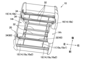
- Fig. 3 is a perspective view showing the bottom of the cargo bed.
- the vehicle 1 is a so-called pickup truck that includes a cabin 2 provided at the front and a cargo bed 10 (cargo box) provided behind the cabin 2.
- the side panels 14 are provided with wheel houses 14h formed in an arch shape to define a space in which wheels (not shown) of the vehicle 1 are arranged.
- the cargo bed 10 forms a storage space in which the space surrounded by the header board 12, tailgate 13, and side panels 14 is closed by the floor panel 11.
- each side panel 14 includes a side inner panel 15 and a side outer panel 16. Note that in FIG. 3, the side outer panel 16 on the left side in the vehicle width direction is omitted.
- the side inner panel 15 is configured as an L-shaped member when viewed from the vehicle front-rear direction (front-rear direction of the coordinate axis of each figure), and forms the end 10a2 (outer end in the vehicle width direction) of the bottom 10a of the cargo bed 10 in the vehicle width direction and forms the inner wall of the side portion 10b. Since the side inner panel 15 includes a portion curved to form an L-shape, it is a member with higher rigidity than the floor panel 11.
- the side outer panel 16 is arranged to cover the side inner panel 15 from the outside and is connected to the side inner panel 15 to form the outer wall of the side portion 10b of the cargo bed 10.
- the side inner panel 15 and the side outer panel 16 have arch-shaped recesses at corresponding positions, which form the wheel house 14h.
- the vehicle 1 is provided with a plurality of body frames for supporting the cabin 2 and the cargo bed 10.
- the body frame includes a chassis frame 30, a plurality of cross members 32, and a plurality of side posts 34.
- the chassis frames 30 are located under the vehicle 1, and are provided in a pair on the left and right sides at a distance from each other in the vehicle width direction, and extend along the vehicle front-rear direction.
- the chassis frames 30 are connected to each wheel (not shown) of the vehicle 1 via a suspension device (not shown) or the like.
- the plurality of cross members 32 are disposed under the vehicle 1 at a distance from each other in the vehicle front-rear direction, and extend along the vehicle width direction.
- the bed support structure 20 of the vehicle 1 of the embodiment will be described.
- the cross members 32 included in the bed support structure 20 are referred to as the "cross members 40”
- the side posts 34 included in the bed support structure 20 are referred to as the "side posts 60.”
- the bed support structure 20 includes the chassis frame 30, the cross members 40, the reinforcements 50 (FIGS. 4 to 6, 8), the side posts 60 (fixing members), and the mount members 90 (FIG. 4).
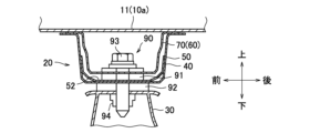
- Figure 4 is a cross-sectional view taken along line A-A in Figure 2.
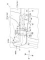
- Figure 5 is an enlarged perspective view showing the area enclosed by the dashed line in Figure 3.
- Figure 6 is an exploded perspective view showing the components of the bed support structure 20.
- Figure 7 is a top view showing the cross member 40.
- Figure 8 is a perspective view showing the reinforcement 50.
- Figure 9 is a top view showing a first portion of the side post 60.
- Figure 10 is a perspective view showing a second portion of the side post 60.
- the coordinate axes in each figure represent the directions when each component of the bed support structure 20 is applied to the vehicle 1.
- the side posts 60 are provided in a pair on the left and right, and one is fixed to each of the outer ends 401 of the cross member 40.
- Each side post 60 includes a first portion 70 and a second portion 80, as shown in Figures 5 and 6.
- the first portion 70 extends in the vehicle width direction along the bottom 10a of the cargo bed 10 above the cross member 40 and the reinforcement 50. Specifically, the first portion 70 is located below the side inner panel 15 that constitutes the bottom 10a. As shown in FIG. 5, the first portion 70 extends from a position inside the mounting bolt insertion hole 40a of the cross member 40 toward the outside in the vehicle width direction, and extends to a position inside the side end of the cargo bed 10 (the outer surface of the side inner panel 15). The outer end 701 in the vehicle width direction of the first portion 70 protrudes outward in the vehicle width direction beyond the outer end 401 of the cross member 40 and the outer end 501 of the reinforcement 50.
- the first part 70 includes a U-shaped portion 71 having a U-shaped cross section as viewed in the vehicle width direction, and two flange portions 72 extending from each side portion 712 of the U-shaped portion 71 to the front side and the rear side in the vehicle longitudinal direction.
- the first part 70 has two abutment portions 711t protruding from the bottom surface portion 711 of the U-shaped portion 71.
- the U-shaped portion 71 of the first part 70 is accommodated in the reinforcement 50 so that the two abutment portions 711t abut against the bottom surface portion 511 of the reinforcement 50.
- the first part 70 is fixed to the bottom portion 10a of the cargo bed 10 by fastening together with the flange portion 42 of the cross member 40 at the two flange portions 72.
- the second part 80 is fixed to the first part 70 by fastening, with the U-shaped part 81 housed within the outer end 501 of the first part 70 so that the bottom surface 811 of the U-shaped part 81 abuts against the bottom surface 711 of the first part 70.
- the first part 70 and the second part 80 are joined (fixed) at the spot welded part 70d ( Figure 5).
- the fixing position 150 (i.e., the spot welded portion 70d) between the first portion 70 and the second portion 80 is located outside the outer end portion 401 of the cross member 40 in the vehicle width direction, and is located below the side inner panel 15 that constitutes the bottom portion 10a.
- the second portion 80 is also fixed to the bottom portion 10a and the side portion 10b of the cargo bed 10 by fastening at two flange portions 82.
- the cross member 40, the reinforcement 50, the first portion 70, and the second portion 80 (side post 60) are arranged from the bottom in the following order: cross member 40, reinforcement 50, first portion 70 (side post 60), second portion 80 (side post 60).
- the mount member 90 includes a first vibration-damping member 91 and a second vibration-damping member 92.
- the first vibration-damping member 91 and the second vibration-damping member 92 are formed in a cylindrical shape from an elastic material such as a rubber material.
- the first vibration-damping member 91 and the second vibration-damping member 92 have an insertion hole in the center thereof through which a bolt 93 is inserted.
- the first vibration-damping member 91 is placed on the mounting portion 52 of the reinforcement 50, and is inserted into the bottom surface portion 711 of the first portion 70 of the side post 60 through a mount insertion hole 70a formed in the first portion 70.
- the second vibration-damping member 92 is placed on the upper surface of the chassis frame 30 so as to be aligned coaxially with the first vibration-damping member 91.
- bolts 93 are inserted into the first vibration-damping member and the second vibration-damping member 92 from the bottom 10a side of the loading platform 10, and the bolts 93 are fastened to nuts 94 arranged on the underside of the chassis frame 30.
- the bolts 93 are inserted into the cross member 40, the reinforcement 50, and the first part 70 of the side post 60 through the mounting bolt insertion holes 40a, 50a and the mounting insertion hole 70a.
- the chassis frame 30, the cross member 40, and the reinforcement 50 are fastened to each other via the mounting member 90. Therefore, the location where the mounting bolt insertion holes 40a, 50a and the mounting insertion hole 70a are formed becomes the chassis fixing part 100 where the chassis frame 30, the cross member 40, and the reinforcement 50 are fixed, as shown in FIG. 5.
- the cross member 40, the reinforcement 50, and the first part 70 of the side post 60 are fixed together by inserting bolts (not shown) into the first through holes 40b, 50b, and 70b, and fastening the bolts to nuts (not shown). Therefore, the location where the first through holes 40b, 50b, and 70b are formed becomes the first fixing part 110 where the cross member 40, the reinforcement 50, and the first part 70 of the side post 60 are fixed together by fastening the bolts. Furthermore, the cross member 40, the reinforcement 50, and the first part 70 of the side post 60 are fixed together by inserting bolts (not shown) into the second through holes 40c, 50c, and 70c, and fastening the bolts to nuts (not shown).
- the location where the second through holes 40c, 50c, and 70c are formed becomes the second fixing part 120 where the cross member 40, the reinforcement 50, and the first part 70 are fixed together.
- the cross member 40, the reinforcement 50, and the first portion 70 may be connected by other methods, such as welding.
- the first fixing part 110 is located inside the chassis fixing part 100 in the vehicle width direction
- the second fixing part 120 is located outside the chassis fixing part 100 in the vehicle width direction.
- the first fixing part 110 and the second fixing part 120 are provided on both sides of the chassis fixing part 100 in the vehicle width direction.
- the mounting bolt insertion holes 40a, 50a and the mount insertion hole 70a, the first insertion holes 40b, 50b, 70b and the second insertion holes 40c, 50c, 70c are aligned in a straight line along the vehicle width direction at overlapping positions in the vehicle fore-and-aft direction, so the chassis fixing part 100, the first fixing part 110 and the second fixing part 120 are also positioned at overlapping positions in the vehicle fore-and-aft direction.
- the distance from the chassis fixing part 100 to the first fixing part 110 corresponds to the first distance L1
- the distance from the chassis fixing part 100 to the second fixing part 120 corresponds to the second distance L2
- the first distance L1 is smaller than the second distance L2.
- the load transmitted from the wheels (not shown) to the chassis frame 30 is input to the cross member 40 and the reinforcement 50 via the mount member 90 at the chassis fixing part 100.
- the load input to the cross member 40 and the reinforcement 50 is then transmitted from the first fixing part 110 and the second fixing part 120 to the first part 70 of the side post 60, and is further transmitted from the first part 70 to the second part 80 at the fixing position 150.
- the cross member 40 and the chassis frame 30 are fixed to each other by the chassis fixing part 100 provided at the outer end 401 (outer end in the vehicle width direction) of the cross member 40, and the cross member 40 and the side post 60 (fixing member) are fixed to each other by the first fixing part 110 located inside the chassis fixing part 100 in the vehicle width direction and the second fixing part 120 located outside the chassis fixing part 100 in the vehicle width direction.
- the load input from the chassis frame 30 to the cross member 40 can be received by the first fixing part 110 and the second fixing part 120 provided on both sides of the chassis fixing part 100 in the vehicle width direction. Therefore, compared to a case where the fixing position between the first part 70 of the side post 60 and the cross member 40 is only on the outer side of the chassis fixing part 100 in the vehicle width direction, the load can be efficiently released to the first part 70 of the side post 60, and stress generated near the chassis fixing part 100 can be reduced. Therefore, with the cargo bed support structure 20 of the vehicle 1, it is possible to improve durability near the chassis fixing part 100.
- the side post 60 extends along the bottom 10a and side 10b of the cargo bed 10, and the first fixing part 110 and the second fixing part 120 are located below the bottom 10a.
- This configuration increases the rigidity of the chassis fixing part 100 on the outer side in the vehicle width direction, improving durability, compared to when the second fixing part 120 is provided on the side 10b of the cargo bed 10, for example.
- the cross member 40 can be extended to the side 10b of the cargo bed 10, the first fixing part 110 and the second fixing part 120 may be located to the side of the side 10b.
- the cross member 40 and the side post 60 are fastened to each other by bolts at the first fixing portion 110 and the second fixing portion 120. This configuration allows the cross member 40 and the side post 60 to be firmly fixed to each other. As mentioned above, the cross member 40 and the side post 60 may also be fixed to each other by other methods such as welding.
- the chassis fixing part 100, the first fixing part 110 and the second fixing part 120 are also arranged at overlapping positions in the vehicle fore-and-aft direction.
- This configuration prevents the load input from the chassis frame 30 to the cross member 40 from being transmitted to a position offset in the vehicle fore-and-aft direction relative to the first part 70 of the side post 60, thereby suppressing the occurrence of twisting in the cross member 40 and the side post 60.
- the chassis fixing part 100, the first fixing part 110 and the second fixing part 120 may be arranged at offset positions in the vehicle fore-and-aft direction.
- the first distance L1 from the chassis fixing part 100 to the first fixing part 110 and the second distance L2 from the chassis fixing part 100 to the second fixing part 120 are smaller than the first distance L1 (either one) than the second distance L2 (either other).
- the length of the side post 60 (first part 70) on the first fixing part 110 side (one side) located closer to the chassis fixing part 100 can be relatively shortened between the first fixing part 110 and the second fixing part 120.
- the second distance L2 may be smaller than the first distance L1 as for the first distance L1 and the second distance L2. This allows stable support of the cargo bed 10 on the outer side in the vehicle width direction.
- the first distance L1 and the second distance L2 may be the same size.
- the reinforcement 50 is fixed to the cross member 40 by the chassis fixing part 100, and is fixed to the first part 70 by the first fixing part 110 and the second fixing part 120.
- the reinforcement 50 is provided within a range including the chassis fixing part 100, the first fixing part 110 and the second fixing part 120 in the vehicle width direction, and is overlapped in the vertical direction with the cross member 40 and the first part 70 of the side post 60.
- the reinforcement 50 may be provided only within the range including the chassis fixing part 100.
- the reinforcement 50 may be omitted.
- the cross member 40, the reinforcement 50 and the side post 60 are arranged in the following order from the bottom: cross member 40, reinforcement 50, side post 60.
- the reinforcement 50 is arranged adjacent to the cross member 40 to which the load is input from the chassis frame 30, so that the durability of the cross member 40 can be further improved.
- the cross member 40, the reinforcement 50 and the side post 60 may be arranged in a different order.
- the cargo bed 10 also includes a floor panel 11 that constitutes the central portion 10a1 (central portion in the vehicle width direction) of the bottom portion 10a, and a side inner panel 15 (side panel 14) that is fixed to the floor panel 11 and constitutes the end portion 10a2 (outer end portion in the vehicle width direction) and the side portion 10b of the bottom portion 10a, and the chassis fixing portion 100, the first fixing portion 110, and the second fixing portion 120 are located below the side inner panel 15.
- the load transmitted to the chassis fixing portion 100, the first fixing portion 110, and the second fixing portion 120 is further transmitted to the side inner panel 15.
- the chassis fixing portion 100, the first fixing portion 110, and the second fixing portion 120 may be located below the floor panel 11.
- the cargo bed 10 also forms a wheel house 14h in which the wheels are arranged, and the cross member 40 and the side post 60 are arranged adjacent to the wheel house 14h, forward of the wheel house 14h in the vehicle's fore-and-aft direction.
- the load transmitted from the chassis frame 30 to the cross member 40 and the side post 60 is transmitted to the vicinity of the wheel house 14h, which has a relatively high rigidity. Therefore, deformation of the cargo bed 10 can be suppressed.
- the cross member 40 and the side post 60 may be arranged adjacent to the wheel house 14h, rearward of the wheel house 14h in the vehicle's fore-and-aft direction, or may not be adjacent to the wheel house 14h.
- the side post 60 includes a first portion 70 that is fixed to the outer end 401 of the cross member 40, and a second portion 80 that is fixed to the first portion 70 on the outer side of the outer end 401 in the vehicle width direction.
- the side post 60 is divided into the first part 70 and the second part 80, the side post 60 is easily deformed near the fixing position 150 between the first part 70 and the second part 80.
- the load input from the chassis fixing part 100 to the cross member 40 and transmitted to the first part 70 can be efficiently released by the deformation of the side post 60, and the stress generated near the chassis fixing part 100 can be reduced.
- the fixing position 150 between the first part 70 and the second part 80 does not overlap with the cross member 40 and the deformation of the side post 60 is not suppressed by the cross member 40, the side post 60 is more easily deformed. As a result, the load can be released more effectively and the stress near the chassis fixing part 100 can be further reduced. Therefore, according to the cargo bed support structure 20 of the vehicle 1, it is possible to improve the durability near the chassis fixing part 100.
- the side post 60 extends along the bottom 10a and side 10b of the cargo bed 10, and the fixing position 150 between the first part 70 and the second part 80 is located below the bottom 10a.
- the fixing position 150 between the first part 70 and the second part 80 can be located closer to the chassis fixing part 100 than when the fixing position 150 is located on the side 10b of the cargo bed, and the load input from the chassis frame 30 to the cross member 40 can be efficiently released at the fixing position 150.
- the first part 70 may be formed as an L-shaped member extending to the side 10b, and the fixing position 150 between the first part 70 and the second part 80 may be located to the side of the side 10b.
- the first portion 70 also extends from a position on the inside of the chassis fixing portion 100 in the vehicle width direction to a position on the inside of the side end of the cargo bed 10 in the vehicle width direction. With this configuration, the load input to the cross member 40 at the chassis fixing portion 100 can be received by the first portion 70 extending on both sides of the chassis fixing portion 100 in the vehicle width direction, and then efficiently released at the fixing position 150.
- the first portion 70 may also be provided at a position on the outside of the chassis fixing portion 100 in the vehicle width direction.
- the cross member 40, the first portion 70, and the second portion 80 are arranged in the following order from the bottom: cross member 40, first portion 70, second portion 80.
- This configuration allows the load input to the cross member 40 at the chassis fixing portion 100 to be released while being transmitted to the first portion 70 and then the second portion 80, thereby reducing the load transmitted directly from the cross member 40 to the cargo bed, and suppressing deformation of the cargo bed 10.
- the cross member 40, the first portion 70, and the second portion 80 may be arranged in a different order.
- the first portion 70 is located below the side inner panel 15 (side panel 14). This configuration allows the load to be transmitted from the first portion 70 to the side inner panel 15, which has a relatively high rigidity, thereby suppressing deformation of the cargo bed 10.
- the chassis fixing portion 100 and the first portion 70 may be located below the floor panel 11.
- the side posts 60 do not have to extend along the side portions 10b as long as they extend along the bottom portion 10a of the cargo bed 10.
- the mounting members 90 may be omitted, and the chassis frame 30 and the cross members 40 may be fixed to each other by bolting or the like.
- the fixing position 150 between the first portion 70 and the second portion 80 may be located on the outer side in the vehicle width direction of the fixing portion between the cross member 40 and the first portion 70 (i.e., the second fixing portion 120) and on the inner side in the vehicle width direction of the outermost end of the cross member 40 in the vehicle width direction. Even with this configuration, if the portion of the cross member 40 located on the outer side in the vehicle width direction from the fixing position 150 is not fixed to any of the floor panel 11, the first portion 70, and the second portion 80, the deformation of the side post 60 can be utilized to reduce the stress generated near the chassis fixing portion 100.
Landscapes
- Engineering & Computer Science (AREA)
- Chemical & Material Sciences (AREA)
- Combustion & Propulsion (AREA)
- Transportation (AREA)
- Mechanical Engineering (AREA)
- Body Structure For Vehicles (AREA)
Abstract
Description
2 キャビン
10 荷台
10a 底部
10a1 中央部(車幅方向中央部)
10a2 端部(車幅方向外側端部)
10b 側部
11 フロアパネル
14 サイドパネル
14h ホイールハウス
15 サイドインナパネル
20 荷台支持構造
30 シャシフレーム
32、40 クロスメンバ
34、60 サイドポスト(固定部材)
40a、50a マウント用ボルト挿通孔
40b、50b、70b 第1挿通孔
40c、50c、70c 第2挿通孔
41、71、81 U字形状部
401、501、701 外側端部(車幅方向外側端部)
42、72、82 フランジ部
50 リンフォース
52 載置部
70 第1部分
70a マウント挿通孔
80 第2部分
90 マウント部材
100 シャシ固定部
110 第1固定部
120 第2固定部
150 固定位置
L1 第1距離
L2 第2距離
Claims (8)
- 車両の荷台の下方に位置するシャシフレームと、
前記荷台の底部に沿って車幅方向に延在し、前記シャシフレームと前記荷台の前記底部とにそれぞれ固定されるクロスメンバと、
前記荷台の前記底部に沿って車幅方向に延在し、前記クロスメンバの車幅方向外側端部および前記荷台の前記底部にそれぞれ固定される固定部材とを備え、
前記クロスメンバと前記シャシフレームとは、前記クロスメンバの前記車幅方向外側端部に設けられたシャシ固定部によって互いに固定され、
前記固定部材は、前記クロスメンバの前記車幅方向外側端部に固定される第1部分と、前記クロスメンバと前記第1部分との固定部よりも車幅方向外側で前記第1部分と固定される第2部分とを含む車両の荷台支持構造。 - 前記第1部分と前記第2部分との固定位置は、前記クロスメンバの前記車幅方向外側端部よりも車幅方向外側に配置されている請求項1に記載の車両の荷台支持構造。
- 前記固定部材は、前記荷台の前記底部と側部とに沿って延在し、
前記第1部分と前記第2部分との固定位置は、前記底部の下方に位置する
請求項1または2に記載の車両の荷台支持構造。 - 前記第1部分は、前記シャシ固定部よりも車幅方向内側の位置から前記荷台の側端よりも車幅方向内側の位置まで延在する請求項1から3のいずれか1項に記載の車両の荷台支持構造。
- 前記クロスメンバ、前記第1部分および前記第2部分は、下側から前記クロスメンバ、前記第1部分、前記第2部分の順に配置される請求項1から4のいずれか1項に記載の車両の荷台支持構造。
- 前記荷台は、前記底部の車幅方向中央部を構成するフロアパネルと、前記フロアパネルに固定され、前記底部の車幅方向外側端部と側部とを構成するサイドパネルとを含み、
前記シャシ固定部は、前記サイドパネルの下方に位置する
請求項1から5のいずれか1項に記載の車両の荷台支持構造。 - 前記第1部分は、前記サイドパネルの下方に位置する請求項6に記載の車両の荷台支持構造。
- 前記荷台は、車輪が配置されるホイールハウスを形成し、
前記クロスメンバおよび前記固定部材は、前記ホイールハウスに対して車両前後方向のいずれか一方側で、前記ホイールハウスに隣接して配置される
請求項1から請求項7のいずれか1項に記載の車両の荷台支持構造。
Priority Applications (2)
| Application Number | Priority Date | Filing Date | Title |
|---|---|---|---|
| PCT/JP2023/025168 WO2025009166A1 (ja) | 2023-07-06 | 2023-07-06 | 車両の荷台支持構造 |
| JP2025530944A JPWO2025009166A1 (ja) | 2023-07-06 | 2023-07-06 |
Applications Claiming Priority (1)
| Application Number | Priority Date | Filing Date | Title |
|---|---|---|---|
| PCT/JP2023/025168 WO2025009166A1 (ja) | 2023-07-06 | 2023-07-06 | 車両の荷台支持構造 |
Publications (1)
| Publication Number | Publication Date |
|---|---|
| WO2025009166A1 true WO2025009166A1 (ja) | 2025-01-09 |
Family
ID=94171819
Family Applications (1)
| Application Number | Title | Priority Date | Filing Date |
|---|---|---|---|
| PCT/JP2023/025168 Ceased WO2025009166A1 (ja) | 2023-07-06 | 2023-07-06 | 車両の荷台支持構造 |
Country Status (2)
| Country | Link |
|---|---|
| JP (1) | JPWO2025009166A1 (ja) |
| WO (1) | WO2025009166A1 (ja) |
Citations (2)
| Publication number | Priority date | Publication date | Assignee | Title |
|---|---|---|---|---|
| US20100072781A1 (en) * | 2006-05-16 | 2010-03-25 | Werner Mark F | Truck Box Space Frame |
| US9126630B1 (en) * | 2014-06-27 | 2015-09-08 | Ford Global Technologies, Llc | Corner node and assembly for pickup truck box |
-
2023
- 2023-07-06 JP JP2025530944A patent/JPWO2025009166A1/ja active Pending
- 2023-07-06 WO PCT/JP2023/025168 patent/WO2025009166A1/ja not_active Ceased
Patent Citations (2)
| Publication number | Priority date | Publication date | Assignee | Title |
|---|---|---|---|---|
| US20100072781A1 (en) * | 2006-05-16 | 2010-03-25 | Werner Mark F | Truck Box Space Frame |
| US9126630B1 (en) * | 2014-06-27 | 2015-09-08 | Ford Global Technologies, Llc | Corner node and assembly for pickup truck box |
Also Published As
| Publication number | Publication date |
|---|---|
| JPWO2025009166A1 (ja) | 2025-01-09 |
Similar Documents
| Publication | Publication Date | Title |
|---|---|---|
| CN104203724B (zh) | 汽车的前副车架结构 | |
| US11447183B2 (en) | Vehicle structure of frame vehicle | |
| US7905541B2 (en) | Rear vehicle body structure | |
| JP5974475B2 (ja) | 自動車のフロントサブフレーム構造 | |
| JP5549420B2 (ja) | 車両の後部車体構造 | |
| US8894134B2 (en) | Front body of vehicle | |
| JP5870680B2 (ja) | 自動車のフロントサブフレーム構造 | |
| JP5870673B2 (ja) | 自動車のフロントサブフレーム構造 | |
| JP5949044B2 (ja) | フロントサブフレーム構造 | |
| JP2004155219A (ja) | 自動車の車体後部構造 | |
| JP7519032B2 (ja) | 電動車両の下部構造 | |
| KR101705146B1 (ko) | 차량용 서브프레임의 구조 | |
| JP2019006311A (ja) | 車体前部構造 | |
| JP4774976B2 (ja) | 車両の後部車体構造 | |
| CN112455542B (zh) | 车辆用副车架 | |
| JP2009002267A (ja) | 車両用キャニスタの取付構造 | |
| JP6136873B2 (ja) | 自動車の後部車体構造 | |
| CN114620131B (zh) | 车身构造 | |
| JP2008137483A (ja) | 車体前部構造 | |
| WO2025009166A1 (ja) | 車両の荷台支持構造 | |
| WO2025009165A1 (ja) | 車両の荷台支持構造 | |
| JP2001030949A (ja) | 車両の前部車体構造 | |
| KR20220006958A (ko) | 차량용 서브프레임 | |
| JP7332061B2 (ja) | 車両のフレーム構造 | |
| JP2024179902A (ja) | 車両用バッテリの支持構造 |
Legal Events
| Date | Code | Title | Description |
|---|---|---|---|
| 121 | Ep: the epo has been informed by wipo that ep was designated in this application |
Ref document number: 23944413 Country of ref document: EP Kind code of ref document: A1 |
|
| DPE1 | Request for preliminary examination filed after expiration of 19th month from priority date (pct application filed from 20040101) | ||
| ENP | Entry into the national phase |
Ref document number: 2025530944 Country of ref document: JP Kind code of ref document: A |
|
| WWE | Wipo information: entry into national phase |
Ref document number: 2025530944 Country of ref document: JP |
|
| WWE | Wipo information: entry into national phase |
Ref document number: 2601000011 Country of ref document: TH |
|
| NENP | Non-entry into the national phase |
Ref country code: DE |