WO2025009145A1 - 顕微鏡システム - Google Patents
顕微鏡システム Download PDFInfo
- Publication number
- WO2025009145A1 WO2025009145A1 PCT/JP2023/025090 JP2023025090W WO2025009145A1 WO 2025009145 A1 WO2025009145 A1 WO 2025009145A1 JP 2023025090 W JP2023025090 W JP 2023025090W WO 2025009145 A1 WO2025009145 A1 WO 2025009145A1
- Authority
- WO
- WIPO (PCT)
- Prior art keywords
- microscope
- stage
- electron microscope
- revolver
- electron
- Prior art date
- Legal status (The legal status is an assumption and is not a legal conclusion. Google has not performed a legal analysis and makes no representation as to the accuracy of the status listed.)
- Ceased
Links
Images











Classifications
-
- H—ELECTRICITY
- H01—ELECTRIC ELEMENTS
- H01J—ELECTRIC DISCHARGE TUBES OR DISCHARGE LAMPS
- H01J37/00—Discharge tubes with provision for introducing objects or material to be exposed to the discharge, e.g. for the purpose of examination or processing thereof
- H01J37/02—Details
- H01J37/18—Vacuum locks ; Means for obtaining or maintaining the desired pressure within the vessel
-
- H—ELECTRICITY
- H01—ELECTRIC ELEMENTS
- H01J—ELECTRIC DISCHARGE TUBES OR DISCHARGE LAMPS
- H01J37/00—Discharge tubes with provision for introducing objects or material to be exposed to the discharge, e.g. for the purpose of examination or processing thereof
- H01J37/26—Electron or ion microscopes; Electron or ion diffraction tubes
- H01J37/28—Electron or ion microscopes; Electron or ion diffraction tubes with scanning beams
Definitions
- the present invention relates to a microscope system.
- Patent Document 1 describes a scanning electron microscope.
- a first aspect of the microscope system of the present invention includes a stage having a first surface on which a holder for accommodating an object is provided, an electron microscope that irradiates an electron beam onto the object held in the holder to obtain information about the object, a first vacuum forming unit that is arranged to face the first surface of the stage and locally forms a first vacuum region on a portion of the first surface, and a second vacuum forming unit that is arranged to face the second surface of the stage and locally forms a second vacuum region on a portion of the second surface on the opposite side of the stage to the first vacuum forming unit, and the electron microscope irradiates the object in the holder with the electron beam via the first vacuum region while forming the first vacuum region and the second vacuum region.
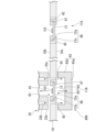
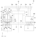
- FIG. 1 is a schematic configuration diagram showing a microscope system according to a first embodiment.
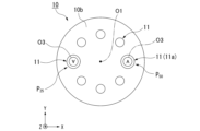
- FIG. 2 is a plan view of a revolver stage of the microscope system.
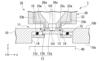
- FIG. 2 is a cross-sectional view of a main part of the revolver stage.
- FIG. 2 is a perspective view of a support member and a sealing member.
- 4 is a cross-sectional view of the support member and the sealing member.
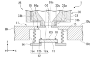
- FIG. 13 is a cross-sectional view of a main part of the revolver stage when the support member is moved downward.
- FIG. 13 is a cross-sectional view of a main part of a microscope system according to a modified example of the first embodiment.
- FIG. 11 is a schematic configuration diagram illustrating a microscope system according to a modified example of the first embodiment.
- 10 is a flowchart showing an example of a procedure of a calibration process in the calibration of the microscope system.
- 11A to 11C are diagrams for explaining the XY calibration process.
- 11A and 11B are diagrams for explaining a coordinate axis correction step in the calibration.
- 10 is a flowchart showing an example of a control method of the microscope system.
- FIG. 2 is a diagram showing an example of a composite image of an object.
- 10A to 10C are diagrams illustrating an example of an optical microscope image acquired in an optical microscope image acquiring step.
- 10A to 10C are diagrams showing examples of electron microscope images acquired in an electron microscope image acquiring step.
- FIG. 4 is a diagram showing an example of an electron microscope image displayed on a display unit.
- FIG. 13 is a cross-sectional view of a main part of a microscope system according to a modified example of the first embodiment.
- 13 is a cross-sectional view of a main part of a microscope system according to a modified example of the first embodiment.
- FIG. 13 is a plan view illustrating a schematic view of a main part of a microscope system according to a modified example of the first embodiment.
- 13A and 13B are diagrams showing examples of both images acquired when a revolver stage is moved in the microscope system.
- FIG. 13 is a diagram showing an example of an optical microscope image.
- FIG. 1 is a diagram showing an example of an electron microscope image.
- FIG. 13 is a diagram showing an example of a state in which both images are superimposed on each other.
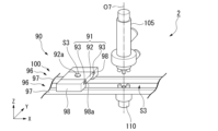
- FIG. 11 is a perspective view of a main part of a microscope system according to a second embodiment.
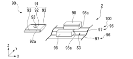
- 13 is a perspective view of the essential parts of the microscope system, showing a state in which the sample holder is removed from the rail.
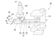
- FIG. FIG. 11 is a perspective view of a main part of a microscope system according to a modified example of the second embodiment.
- the drawings also show an XYZ Cartesian coordinate system as appropriate, and the positional relationships of each part will be explained with reference to this XYZ Cartesian coordinate system.
- the direction parallel to the X-axis is referred to as the "first horizontal direction X”
- the direction parallel to the Y-axis is referred to as the "second horizontal direction Y”
- the direction parallel to the Z-axis is referred to as the "vertical direction Z”.
- the first horizontal direction X, the second horizontal direction Y, and the vertical direction Z are mutually perpendicular directions.
- the positive side (+Z side) of the vertical direction Z toward which the Z-axis arrow points is referred to as "upper” or “upper side”
- the negative side (-Z side) of the vertical direction Z opposite to the side toward which the Z-axis arrow points is referred to as "lower” or “lower side”.
- the vertical direction Z is the height direction.
- the revolver stage 10 is disk-shaped in the XY plane.
- the revolver stage 10 is disposed so that its axis (axis of rotation) O1 is aligned with the vertical direction Z.
- the first horizontal direction X and the second horizontal direction Y are intersecting directions that are perpendicular to (intersect with) the axis O1.
- the revolver stage 10 has a first surface 10b which is an upper surface and a second surface 10c which is a lower surface.
- the first surface 10b and the second surface 10c are each circular.
- the revolver stage 10 is made of a metal such as brass or stainless steel.
- the circumferential direction of the revolver stage 10 will be simply referred to as the circumferential direction.
- Sample Holder A sample holder (holder) 11 that holds an object O3 is formed on the first surface 10b of the revolver stage 10. The object O3 held in the sample holder 11 may be expressed as "object O3 in the sample holder 11.”
- the sample holder 11 reaches the second surface 10c of the revolver stage 10.
- a plurality of sample holders 11 are formed around the axis O1 on the revolver stage 10.
- a plurality of sample holders 11 are formed around the axis O1 on the revolver stage 10 at intervals from each other.
- the control unit 65 can recognize the position of each sample holder 11 by a rotary encoder or a sensor provided on the rotary motor 20 that drives the revolver stage 10.
- the number of sample holders 11 formed on the revolver stage 10 may be one.
- the small diameter hole 12 a opens into the upper surface of the revolver stage 10 .
- the outer diameter of the medium diameter hole 12b is larger than the outer diameter of the small diameter hole 12a.
- the medium diameter hole 12b is disposed below the small diameter hole 12a and communicates with the small diameter hole 12a.
- the outer diameter of the large diameter hole 12c is larger than that of the medium diameter hole 12b.
- the large diameter hole 12c is disposed below the medium diameter hole 12b and communicates with the medium diameter hole 12b.
- the large diameter hole 12c opens to the lower surface of the revolver stage 10.
- a portion located inside the outer periphery of the large diameter hole 12c in a plan view corresponds to the sealing plate 10a.
- the sealing plate 10a has an annular shape.
- the upper surface of the sealing plate 10a is flat.
- the sealing plate 10a is integral with the revolver stage 10, but the sealing plate may be separate from the revolver stage 10. In this case, the sealing plate forms part of the sample holder.
- the support member 13 is disk-shaped.
- the support member 13 is made of a material that transmits light, such as glass.
- the support member 13 transmits visible light.
- the upper end of the support member 13 is disposed in the medium diameter hole 12b of the accommodating hole 12.
- the support member 13 is disposed in the medium diameter hole 12b and the large diameter hole 12c of the accommodating hole 12.
- the upper surface of the support member 13 supports the object O3.
- a conductive transparent film made of ITO (indium tin oxide), TiO2 (titanium dioxide), or the like may be provided on the upper surface of the support member 13. This configuration prevents the object O3 and its surroundings from becoming charged up (electrified) during observation with the electron microscope 25, making it difficult to observe the object O3. Furthermore, it is possible to prevent deterioration of the electron microscope image while removing secondary electrons attached to the object O3.
- annular sealing member 18 is disposed on the upper surface of the support member 13.
- the sealing member 18 is made of an elastic material such as rubber.
- an O-ring is used for the sealing member 18.
- the sealing member 18 is disposed coaxially with the support member 13. As shown in FIG. 3, the sealing member 18 is in contact with the lower surface that defines the medium diameter hole 12b in the revolver stage 10 from below this lower surface.
- the holding member 14 is annular.
- the inner peripheral edge of the holding member 14 supports the outer peripheral edge of the support member 13 from below the outer peripheral edge.
- the inner peripheral edge of the holding member 14 is fixed to the outer peripheral edge of the support member 13.
- the biasing member 15 is a helical spring.
- a first end of the biasing member 15 is fixed to a radially outer portion of the upper surface of the holding member 14.
- a second end of the biasing member 15 opposite to the first end is fixed to a lower surface of the revolver stage 10 that defines the large diameter hole 12c.
- the biasing member 15 biases the holding member 14 upward relative to the revolver stage 10. Therefore, the sealing member 18 is sandwiched between the revolver stage 10 and the support member 13 in the vertical direction Z.
- the sealing member 18 hermetically seals the space between the revolver stage 10 and the support member 13.
- the revolver stage 10 configured as above is supported by a rotary motor 20 so as to be rotatable about an axis O1.
- the revolver stage 10 is a stage that rotates in either direction about an axis O1.
- the electron microscope 25 and the optical microscope 50 are disposed at positions sandwiching the axis O1 in a direction intersecting the axis O1.
- the electron microscope 25 and the optical microscope 50 may be disposed at positions not sandwiching the axis O1 in a direction intersecting the axis O1.
- the sample holder 11 has the accommodation hole 12, the support member (shuttle) 13, the holding member 14, and the biasing member 15.
- the present invention is not limited to this, and the sample holder 11 may be a simple depression (concave when viewed from the XZ plane or the YZ plane).
- the bottom surface of the depression is formed of a light-transmitting material such as glass.
- the shape of the sample holder 11 can be simplified.
- the alignment mark may be a shape that protrudes or is recessed from the upper surface of the revolver stage 10. With this configuration, the user does not need to manually provide alignment marks, and the microscope system 1 can be easily operated.
- the rotary motor 20 is disposed on an axis O1 above the revolver stage 10.
- a drive shaft (not shown) of the rotary motor 20 is fixed to the revolver stage 10.
- the rotary motor 20 rotates the revolver stage 10 about the axis O1.
- the rotary motor 20 moves the revolver stage 10 about the axis O1.
- the rotary motor 20 is equipped with a rotary encoder (not shown).
- the rotary encoder detects the number of rotations of the revolver stage 10 and the rotation angle within one rotation (360°) via a drive shaft. For example, the rotary encoder detects that the revolver stage 10 has rotated 5 times as the number of rotations and 120° as the rotation angle.
- the rotary motor 20 may be configured to move the revolver stage 10 in the vertical direction Z.
- the rotary motor 20 may be disposed below the revolver stage 10 on the axis O1.
- the microscope system 1 preferably includes an XY stroke stage (moving unit) 21.
- the XY stroke stage 21 moves the rotary motor 20 in the first horizontal direction X and the second horizontal direction Y.
- the XY stroke stage 21 moves the revolver stage 10 relatively to the electron microscope 25 and the optical microscope 50 in the first horizontal direction X and the second horizontal direction Y.
- the XY stroke stage 21 moves the revolver stage 10 in a plane parallel to the first surface 10b and the second surface 10c.
- the XY stroke stage 21 may be configured to move the rotary motor 20 in the vertical direction Z.
- the rotary motor 20 and the XY stroke stage 21 may be collectively referred to as a moving stage 23 (see FIG. 1).
- the moving stage 23 rotates the revolver stage 10 around the axis O1.
- the XY stroke stage 21, the electron microscope 25, and the optical microscope 50 are fixed to the frame 22. That is, the revolver stage 10, the rotary motor 20, the XY stroke stage 21, the frame 22, and the electron microscope 25 are connected to one another in this order.
- the frame 22 fixes the moving stage 23 and the electron microscope 25.
- the optical microscope 50 does not have to be fixed to the frame 22 .
- An elastic member 22e made of a material having a smaller elastic modulus than steel may be provided between the center and second end of the connecting member 22a. With this configuration, vibrations generated in the rotary motor 20 can be absorbed by the elastic member 22e and prevented from being transmitted to the optical microscope 50.
- the housing 26 has, for example, a cylindrical shape extending in the vertical direction Z.
- An electron beam path 26a through which the electron beam EB passes is provided inside the housing 26.
- the optical axis direction of the electron beam EB is substantially parallel to the vertical direction Z.
- the electron beam path 26a extends in the vertical direction Z.
- the upper end of the electron beam path 26a is provided with a photoelectric section 28.
- the lower end of the housing 26 is provided with an emission opening (irradiation opening) 26c facing downward.
- the light source unit 27 is fixed to the upper end surface of the housing 26.
- the light source unit 27 is capable of emitting light into the internal space of the housing 26.
- the light emitted from the light source unit 27 into the internal space of the housing 26 is irradiated onto the photoelectric unit 28 provided within the housing 26.
- the photoelectric unit 28 emits an electron beam EB due to the photoelectric effect when light is irradiated onto it.
- the photoelectric unit 28 emits an electron beam EB downward when light from the light source unit 27 is incident on it from above.
- the electron beam EB emitted downward from the photoelectric unit 28 passes through the electron beam path 26a and is emitted downward from the emission opening 26c towards the object O3.
- the emission opening 26c is formed on the central axis O5 of the electron microscope 25, where the electron beam EB is irradiated towards the object O3.
- the central axis O extends in the vertical direction Z.
- the electron microscope 25 has a scanning unit (not shown).
- the scanning unit scans the electron beam EB in the first horizontal direction X and the second horizontal direction Y.
- the exhaust device 30 has a nozzle member 33, a first pump 34, and a second pump 35.
- the nozzle member 33 is annular and surrounds the housing 26 around the central axis O5 of the electron microscope 25. In this embodiment, the central axis O5 passes through the center of the electron beam path 26a.
- the nozzle member 33 has a protruding portion 33a that protrudes downward.
- the protruding portion 33a surrounds the lower end surface 26b of the housing 26 around the central axis O5.
- the nozzle member 33 is provided with a first intake flow path 33b.
- a plurality of first intake flow paths 33b are provided.
- the first intake flow path 33b has an intake opening (suction opening) 33c that opens on the lower end surface of the protruding portion 33a.
- the intake openings 33c in the plurality of first intake flow paths 33b are arranged, for example, at intervals from each other in the circumferential direction around the central axis O5 on the lower end surface of the protruding portion 33a.
- the plurality of intake openings 33c are arranged so as to surround the injection opening 26c around the central axis O5.
- the upper surface of the sealing plate 10a of the revolver stage 10 faces the intake opening 33c.
- the small diameter hole 12a of the sealing plate 10a is formed in a portion facing the exit opening 26c of the sealing plate 10a of the electron microscope 25.
- the small diameter hole 12a is formed in the portion facing the exit opening 26c of the electron microscope 25 of the sealing plate 10a.
- the first pump 34 and the second pump 35 are vacuum pumps.
- the first pump 34 and the first intake passage 33b constitute a first vacuum forming section 37.
- the first pump 34 is, for example, an oil diffusion pump.
- the second pump 35 is, for example, a pump that combines an oil diffusion pump and a turbo molecular pump.
- the first pump 34 is connected to the first intake passage 33b.
- the first pump 34 draws air into the first intake passage 33b through the intake opening 33c. At least a portion of the air inside the protruding portion 33a may be sucked into the first intake passage 33b.
- the second pump 35 can suck air in the electron beam path 26a through the second intake flow path 33d.
- the second intake flow path 33d is connected to, for example, an upper end of the electron beam path 26a. Air in the electron beam path 26a is sucked into the second intake flow path 33d. Note that at least a portion of the air inside the protrusion 33a may be sucked into the second intake flow path 33d.
- a small gap is formed between the lower end surface of the protruding portion 33 a of the nozzle member 33 and the upper surface of the revolver stage 10 .
- the intake opening 33c sucks air in a first vacuum region R1 between the lower end surface of the protruding portion 33a and the sample holder 11 of the revolver stage 10. That is, a so-called local vacuum region is formed in the electron microscope 25 by the first vacuum region R1.
- the first vacuum region R1 is formed locally in a part of the first surface 10b of the revolver stage 10.
- the first vacuum forming part 37 is arranged so as to be able to face the first surface 10b of the revolver stage 10, and forms the first vacuum region R1.
- the local vacuum region is likely to be maintained even when the revolver stage 10 rotates about the axis O1.
- the portion of the revolver stage 10 that is in contact with the first vacuum region R1 is sucked upward.
- the electron microscope 25 observes the object O3 while forming the first vacuum region R1 above the sample holder 11.
- the electron microscope 25 observes the object O3 on the central axis O5 and obtains an electron microscope image that is an image of the object O3.
- the electron microscope 25 irradiates the object O3 contained in the sample holder 11 with an electron beam EB to obtain information about the object O3.
- position (second position) P50 is the position of the sample holder 11 for observation with an optical microscope 50.
- Position (first position) P25 is the position of the sample holder 11 for observation with an electron microscope 25.
- Positions P25 and P50 are disposed at different positions around axis O1.
- Position P50 is a position obtained by rotating position P25 by 180° (half a rotation) around axis O1.
- the revolver stage 10 is movable to move the sample holder 11 to at least a position P25 and a position P50 .
- the revolver stage 10 rotates about an axis O1.
- an object O3 having the shape of the letter "A" at position P50 has the shape of an "A" rotated 180 degrees at position P25 .
- Vacuum cancellation mechanism by second vacuum forming section 1-1-7-1 Vacuum cancellation mechanism by second vacuum forming section 1-1-7-1.
- Vacuum forming section (Type 1) the second vacuum forming part 40 is configured similarly to the first pump 34 of the exhaust device 30. As shown in Fig. 1, the second vacuum forming part 40 is disposed in the space S1 below the revolver stage 10 and the electron microscope 25. The second vacuum forming part 40 is disposed so as to be able to face the second surface 10c of the revolver stage 10.
- the second vacuum forming unit 40 forms a second vacuum region R2 below the sample holder 11 (second side in the thickness direction).
- the second vacuum region R2 together with the first vacuum region R1, sandwiches the sample holder 11 in the vertical direction Z.
- the second vacuum forming unit 40 locally forms the second vacuum region R2 in a part of the second surface 10c of the revolver stage 10 on the opposite side of the revolver stage 10 to the first vacuum forming unit 37.
- the second vacuum forming section 40 sucks the portion of the revolver stage 10 that comes into contact with the second vacuum region R2 downward.
- the rotary motor 20 is a space forming part that forms a space S1 on a central axis O5 in which the second vacuum forming part 40 is disposed.
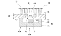
- Second vacuum forming section (type 2) As shown in FIG. 7, the second vacuum forming section 40A may have a communication hole 42 formed in the revolver stage 10 and a region forming member 43.
- the sample holder 11A of the revolver stage 10 has an accommodating hole 46, a support member 13, and a holding member 47.
- the receiving hole 46 has the small diameter hole 12a and the large diameter hole 12c.
- the small diameter hole 12a opens into the lower surface of the revolver stage 10.
- the large diameter hole 12c is disposed above the small diameter hole 12a and communicates with the small diameter hole 12a.
- the large diameter hole 12c opens into the upper surface of the revolver stage 10.
- the support member 13 is disposed on the bottom surface of the revolver stage 10 that defines the large diameter hole 12c.
- the holding member 47 is annular.
- the holding member 47 is disposed on the outer circumferential edge of the support member 13 and is detachably fitted into the large diameter hole 12c of the revolver stage 10.
- the support member 13 is fixed to the revolver stage 10 by being sandwiched between the bottom surface and the holding member 47 in the vertical direction Z.
- the communication hole 42 is formed radially outward of the accommodation hole 46 in the revolver stage 10.
- the communication hole 42 penetrates the revolver stage 10 in the vertical direction Z and communicates with the first vacuum region R1 and the second vacuum region R2.
- the sample holder 11A has a plurality of communication holes 42.
- the plurality of communication holes 42 are arranged radially outward of the accommodation hole 46 at intervals in the circumferential direction of the accommodation hole 46. It is preferable that the plurality of communication holes 42 are formed at positions facing the plurality of intake openings 33c of the electron microscope 25 when the sample holder 11A is set in the electron microscope 25.
- the region forming member 43 has a bottom wall portion 43a and a peripheral wall portion 43b.
- the bottom wall portion 43a is disk-shaped and is disposed below the revolver stage 10 so as to be aligned along a horizontal plane.
- the peripheral wall portion 43b protrudes upward from the outer periphery of the bottom wall portion 43a.
- the peripheral wall portion 43b is formed around the entire circumference of the bottom wall portion 43a. In a plan view, the peripheral wall portion 43b is disposed so as to surround the multiple communication holes 42 of the revolver stage 10.
- the region forming member 43 surrounds the second vacuum region R2 so that the second vacuum region R2 is connected to the revolver stage 10. A small gap is formed between the upper surface of the peripheral wall portion 43 b and the lower surface of the revolver stage 10 .
- the area forming member 43 may be provided in an optical microscope 50 .
- the optical microscope 50 is, for example, an inverted microscope, an upright microscope, or a transmission microscope. In general, an inverted microscope has high resolution (super resolution). 1, the optical microscope 50 is disposed at a different position around the axis O1 from the electron microscope 25. The optical microscope 50 observes an object O3 using visible light L1. The optical microscope 50 acquires information on the object O3 in the sample holder 11 that has been moved to a second position P50 . While acquiring information on the object O3 with the electron microscope 25, the optical microscope 50 acquires information on another object O3.
- the optical microscope 50 is a known inverted microscope.
- the optical microscope 50 has an illumination unit 51 and a lens unit 52.
- the illumination unit 51 is disposed above the revolver stage 10.
- the illumination unit 51 emits visible light L1, which is illumination light, downward.
- the lens unit 52 is disposed below the revolver stage 10.
- the lens unit 52 has a lens 52a that faces upward.
- the lens unit 52 receives the visible light L1 emitted from the illumination unit 51 and transmitted through the object O3 in the sample holder 11.
- the lens unit 52 obtains an optical microscope image that is an image of the object O3.
- the optical microscope 50A may be an upright microscope, as in the microscope system 1A shown in Fig. 8. In this case, the illumination unit 51 of the optical microscope 50A is disposed below the revolver stage 10, and the lens unit 52 is disposed above the revolver stage 10.
- the display unit 55 is a liquid crystal display or the like. As shown in Fig. 1, the display unit 55 has a display surface 56 for displaying an image while scanning. The display unit 55 is connected to the control unit 65 by wire or wirelessly. Based on a signal from the control unit 65, the display unit 55 displays on the display surface 56 an electron microscope image of the object O3 acquired by the electron microscope 25 and an optical microscope image of the object O3 acquired by the optical microscope 50.
- the input unit 60 includes a keyboard 61 and a mouse 62.
- the keyboard 61 and the mouse 62 are connected to the control unit 65 by wire or wirelessly.
- a signal is input from the input unit 60 to the control unit 65 .
- control unit 65 is a PC (Personal Computer).
- the control unit 65 is connected to the rotary motor 20, the XY stroke stage 21, the electron microscope 25, the second vacuum forming unit 40, the optical microscope 50, the display unit 55, and the input unit 60, and controls the rotary motor 20, the XY stroke stage 21, the electron microscope 25, the second vacuum forming unit 40, the optical microscope 50, and the display unit 55.
- the control unit 65 has a CPU (Central Processing Unit) 66 , a ROM (Read Only Memory) 67 , and a RAM (Random access memory) 68 .
- the CPU 66 is a part that performs various controls and processes.
- the ROM 67 and the RAM 68 are storage units that store (also described as save, store, etc.) information. Storing conditions related to the control of the microscope system 1 in the ROM 67 or the RAM 68 is also described as "setting", etc.
- the RAM 68 stores, for each of the multiple sample holders 11, the optical positional relationship in the vertical direction Z between the object O3 and the focal position of the optical microscope 50.
- the optical positional relationship is the relationship between the focal position of the optical microscope 50 acquired by a Z calibration step Sc2 described later and the acceleration voltage (applied voltage) applied to the electron beam EB. This relationship allows the control unit 65 to calculate the value of the acceleration voltage that allows the electron microscope 25 to be focused on a portion of the object O3 on which the optical microscope 50 is focused when the height H of the lens 52a is a certain value.
- the relationship between the height H of the lens 52a and the acceleration voltage applied to the electron beam EB is, for example, linear.
- the relationship between the height H of the lens 52a and the acceleration voltage applied to the electron beam EB is stored in, for example, the ROM 67 or the RAM 68. Then, during focus control of the electron microscope 25 or the optical microscope 50, the relationship between the height H of the lens 52a and the acceleration voltage applied to the electron beam EB is used.
- the display unit 55, input unit 60, and control unit 65 may be integrated into a tablet PC (Personal Computer).
- the calibration of the microscope system includes a calibration step Sc for performing a calibration for correcting or detecting the relative relationship between the revolver stage 10, the electron microscope 25, and the optical microscope 50.
- 9 is a flow chart showing an example of the procedure of the calibration step Sc of the present embodiment. As shown in FIG 9, the calibration step Sc of the present embodiment includes an XY calibration step Sc1 and a Z calibration step Sc2.
- the XY calibration process Sc1 is a process for calibrating the relative positions of the revolver stage 10, the electron microscope 25, and the optical microscope 50 in the first horizontal direction X and the second horizontal direction Y.
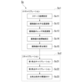
- the XY calibration process Sc1 includes a stage coordinate setting process Sc11, a horizontal position adjustment process Sc12, a lens angle adjustment process Sc13, a coordinate axis correction process Sc14, and an origin correction process Sc15.
- a first vacuum region R1 is formed above the sample holder 11. 7, for the sample holder 11A, the first pump 34 is driven to suck in air from the first intake flow path 33b, and the air between the region forming member 43 and the revolver stage 10 is sucked in through the communication hole 42 of the revolver stage 10. This forms a second vacuum region R2.
- the first vacuum region R1 sucks the revolver stage 10 upward as indicated by an arrow A1, while the second vacuum region R2 sucks the revolver stage 10 downward as indicated by an arrow A2.
- the stage coordinate setting step Sc11 is a step of setting an XY coordinate system that is the reference for the movement of the revolver stage 10.
- the XY coordinate system that is the reference for the movement of the revolver stage 10 is, for example, a coordinate system indicated by the X-axis and the Y-axis shown in each drawing.
- various information required for setting the coordinates of the revolver stage 10 is input to the control unit 65 from the user.
- the various information is not particularly limited, and includes information about the revolver stage 10 such as size, information about the electron microscope 25, information about the optical microscope 50, and environmental information about the environment in which the microscope system 1 is placed.
- the control unit 65 sets an XY coordinate system that serves as a reference for the movement of the revolver stage 10.
- the XY coordinate system that serves as a reference for the movement of the revolver stage 10 may be simply referred to as the "coordinate system of the revolver stage 10.”
- a first origin OPs corresponding to the optical microscope 50 and a second origin SPs corresponding to the electron microscope 25 are set as shown in Fig. 10.
- Fig. 10 is a diagram for explaining the XY calibration step Sc1.
- the first origin OPs corresponding to the optical microscope 50 is, for example, a position set as an initial position for moving a predetermined sample holder 11 (hereinafter referred to as sample holder 11a) of the revolver stage 10 below the optical microscope 50.
- the second origin SPs corresponding to the electron microscope 25 is, for example, a position set as an initial position for moving the sample holder 11a of the revolver stage 10 below the electron microscope 25.
- the horizontal position adjustment step Sc12 is a step of adjusting the horizontal position of each of the microscopes 25, 50.
- the optical microscope 50 and the electron microscope 25 are moved in the first horizontal direction X and the second horizontal direction Y to adjust the horizontal position of the optical microscope 50 and the horizontal position of the electron microscope 25.
- the movement of each of the microscopes 25, 50 in the horizontal position adjustment step Sc12 may be performed manually by a user or the like, or may be performed automatically by a transport device or the like.
- the movement of each microscope 25, 50 in the horizontal position adjustment step Sc12 is performed so as to bring the center of the range imaged by each microscope 25, 50 closer to the first origin OPs and the second origin SPs, respectively, in the XY coordinates set in the stage coordinate setting step Sc11.
- the optical microscope 50 is moved so that the center OP of the range imaged by the optical microscope 50 approaches the first origin OPs, and the electron microscope 25 is moved so that the center SP of the range imaged by the electron microscope 25 approaches the second origin SPs.
- the center OP of the range imaged by the optical microscope 50 is the center of the frame FO of the optical microscope 50.
- the center SP of the range imaged by the electron microscope 25 is the center of the frame FS of the electron microscope 25.
- the frames FO and FS are rectangular with a long side.
- the vertical and horizontal directions of the frame FO correspond to the axial directions of the coordinate system (OM coordinate system) of the optical microscope 50.
- the coordinate system of the optical microscope 50 is composed of an XO axis extending in the horizontal direction of the frame FO and a YO axis extending in the vertical direction of the frame FO.
- the center OP of the frame FO is the origin of the coordinate system of the optical microscope 50, and is the point where the XO axis and the YO axis intersect.
- the vertical and horizontal directions of the frame FS correspond to the axial directions of the coordinate system of the electron microscope 25.
- the coordinate system (SEM coordinate system) of the electron microscope 25 is made up of an XS axis extending in the horizontal direction of the frame FS and a YS axis extending in the vertical direction of the frame FS.
- the center SP of the frame FS is the origin of the coordinate system of the electron microscope 25 and is the point where the XS axis and the YS axis intersect.
- each microscope 25, 50 in the horizontal position adjustment step Sc12 may be performed so that the center position of the range imaged by each microscope 25, 50 is aligned with each origin provided in the coordinate system of the revolver stage 10 within a range that can be seen with the naked eye.
- the center OP of the frame FO and the first origin OPs are mutually shifted within a sufficiently small range
- the center SP of the frame FS and the second origin SPs are mutually shifted within a sufficiently small range.
- FIG. 10 shows a case where the centers OP, SP of the frames FO, FS are shifted from the first origin OPs and the second origin SPs, respectively, after the horizontal position adjustment step Sc12.
- the horizontal position adjustment step Sc12 only one of the optical microscope 50 and the electron microscope 25 may be moved. Also, if the first origin OPs and the second origin SPs set in the stage coordinate setting step Sc11 coincide with the center of the range imaged by the microscopes 25 and 50 corresponding to each origin, respectively, the horizontal position adjustment step Sc12 does not need to be provided.
- the lens angle adjustment step Sc13 is a step of adjusting the lens angles of the microscopes 25 and 50.
- the lens 52a of the optical microscope 50 is rotated about an axis extending in the vertical direction Z to adjust the angle of the lens 52a.
- the electron lens 29 of the electron microscope 25 is rotated about an axis extending in the vertical direction Z to adjust the angle of the electron lens 29.
- the angle adjustment of each lens may be performed manually by a user or automatically using an adjustment device.
- the angle adjustment of the lens of each microscope 25, 50 is performed so that the vertical and horizontal directions of the frame of each microscope 25, 50 approach each axis of the XY coordinate system.
- the angle adjustment of the lens 52a of the optical microscope 50 is performed so that the horizontal direction of the frame FO approaches the first horizontal direction X and the vertical direction of the frame FO approaches the second horizontal direction Y.
- the angle adjustment of the electron lens 29 of the electron microscope 25 is performed so that the horizontal direction of the frame FS approaches the first horizontal direction X and the vertical direction of the frame FS approaches the second horizontal direction Y.
- the lens angle adjustment of each microscope 25, 50 in the lens angle adjustment step Sc13 may be performed so that the vertical and horizontal directions of each frame FO, FP are aligned with each axis of the XY coordinate system within a range that can be seen by the naked eye.
- the vertical and horizontal directions of the frame FO of the optical microscope 50 are tilted within a sufficiently small range with respect to the first horizontal direction X and the second horizontal direction Y
- the vertical and horizontal directions of the frame FS of the electron microscope 25 are tilted within a sufficiently small range with respect to the first horizontal direction X and the second horizontal direction Y.
- FIG. 10 shows a state in which, after the lens angle adjustment step Sc13, the vertical and horizontal directions of each of the frames FO and FS are inclined with respect to the first horizontal direction X and the second horizontal direction Y.
- the inclination of the frame FO with respect to the XY coordinate system and the inclination of the frame FS with respect to the XY coordinate system are different from each other.
- the control unit 65 rotates the revolver stage 10 around the axis O1 while maintaining the alignment mark M3 positioned within the frame FO of the optical microscope 50.
- Figure 11 shows, for example, the case where the revolver stage 10 is moved in the second horizontal direction Y, as indicated by the white arrow.
- the position of the alignment mark M3 in the frame FO of the optical microscope 50 moves only in the YO-axis direction relative to the frame FO, and does not move in the XO-axis direction.
- the control unit 65 moves the revolver stage 10 for the electron microscope 25 in the same manner as for the optical microscope 50 described above, and obtains a correction value for correcting the coordinate system of the electron microscope 25 to match the coordinate system of the revolver stage 10.
- the coordinate systems of each microscope 25, 50 can be corrected to match the coordinate system of the revolver stage 10. Therefore, even if the coordinate system of the optical microscope 50 and the coordinate system of the electron microscope 25 are misaligned, correction can be made to align the coordinate systems of each microscope 25, 50.
- the acquisition of the correction values for the optical microscope 50 and the acquisition of the correction values for the electron microscope 25 may be performed first.
- the origin correction step Sc15 is a step of acquiring correction values for correcting the first origin OPs and the second origin SPs set in the coordinate system of the revolver stage 10 to match the origins of the microscopes 25, 50.
- the control unit 65 moves the revolver stage 10 so that the origin STO on the revolver stage 10 coincides with the first origin OPs, similar to the coordinate axis correction step Sc14.
- control unit 65 can perform first origin calibration to associate the origin (center OP) of the coordinate system of the optical microscope 50 with the first origin OPs of the coordinate system of the revolver stage 10.
- control method of the microscope system includes performing first origin calibration to associate the origin of the coordinate system of the optical microscope 50 with the first origin OPs of the coordinate system of the revolver stage 10.
- control unit 65 can perform second origin calibration to associate the origin (center SP) of the coordinate system of the electron microscope 25 with the second origin SPs of the coordinate system of the revolver stage 10.
- control method of the microscope system includes performing second origin calibration to associate the origin of the coordinate system of the electron microscope 25 with the second origin SPs of the coordinate system of the revolver stage 10.
- an origin correction step Sc15 the control unit 65 uses the correction value acquired by the above-mentioned first origin calibration and the correction value acquired by the second origin calibration to acquire a correction value for performing a correction to align the origin of the coordinate system of the optical microscope 50 with the origin of the coordinate system of the electron microscope 25.
- the control unit 65 to associate the origin of the coordinate system of the optical microscope 50 with the origin of the coordinate system of the electron microscope 25.
- the control method of the microscope system includes relating the positions of the origin (center OP) of the coordinate system of the optical microscope 50 and the origin (center SP) of the coordinate system of the electron microscope 25 based on the first origin calibration and the second origin calibration.
- the Z calibration step Sc2 is a step of associating the position of the object O3 in the vertical direction Z with the focal condition when the object O3 is imaged by each microscope 25, 50. As shown in Fig. 9, the Z calibration step Sc2 includes a first focal point calibration step Sc21, a second focal point calibration step Sc22, and a focal condition associating step Sc23.
- the first focus calibration step Sc21 is a step of performing first focus calibration for determining the focusing conditions of the optical microscope 50 at multiple portions of the object O3 using the optical microscope 50.
- the control unit 65 images a portion of a sample as the object O3 accommodated in the sample holder 11 of the revolver stage 10 using the optical microscope 50.
- the sample has, for example, multiple portions at different positions in the height direction (vertical direction Z).
- the control unit 65 stores the condition when the optical microscope 50 is focused on a part of the sample imaged by the optical microscope 50.
- the control unit 65 stores the value of the height H of the lens 52a when the optical microscope 50 is focused on a part of the sample imaged by the optical microscope 50.
- the control unit 65 performs a first focus calibration to determine the conditions (the value of the height H of the lens 52a) for focusing the optical microscope 50 on a part of the sample (object O3).
- the control unit 65 executes the same process for multiple parts of the sample that are different in height, thereby obtaining the heights H of the lens 52a corresponding to the multiple parts of the sample, and determining the conditions for focusing the multiple parts of the sample in the optical microscope 50.
- the method of focusing the optical microscope 50 on a portion of the sample in the first focus calibration step Sc21 is not particularly limited.
- the optical microscope 50 may be focused on a portion of the sample using an autofocus function, or the user may manually focus on a portion of the sample.
- the optical microscope 50 may be focused on a portion of the sample using both the autofocus function and the user's manual focus.
- the method of determining whether or not the optical microscope 50 is focused on a portion of the sample in the first focus calibration step Sc21 is not particularly limited.
- the control unit 65 may analyze the image captured by the optical microscope 50 to determine whether or not the optical microscope 50 is focused on a portion of the sample.
- the user may visually inspect the image captured by the optical microscope 50 to determine whether or not the optical microscope 50 is focused on a portion of the sample.
- the user may determine whether or not the optical microscope 50 is focused on a portion of the sample based on both the data analyzed by the control unit 65 and visual judgment.
- the second focus calibration step Sc22 is a step of performing a second focus calibration in the electron microscope 25 to determine the focusing conditions of the electron microscope 25 in multiple parts of the object O3.
- the control unit 65 images the sample used in the first focus calibration step Sc21 with the electron microscope 25.
- the control unit 65 images the multiple parts of the sample for which the focusing conditions were determined in the first focus calibration step Sc21 with the electron microscope 25.
- control unit 65 Each time the control unit 65 captures images of the multiple portions of the sample, it stores the conditions under which the electron microscope 25 is in focus. In this embodiment, the control unit 65 stores, for each of the multiple portions of the sample, the excitation current of the lens used for focus adjustment when the electron microscope 25 is in focus and the acceleration voltage value applied to the electron beam EB. In this way, in the second focus calibration step Sc22, the control unit 65 performs a second focus calibration to determine the conditions for focusing on a part of the sample (object O3) in the electron microscope 25 (the excitation current of the lens used for focus adjustment and the acceleration voltage value applied to the electron beam EB).
- the method of focusing the electron microscope 25 on a portion of the sample in the second focus calibration step Sc22 is not particularly limited.
- the portion of the sample may be focused on using the autofocus function of the electron microscope 25, the portion of the sample may be focused on manually by the user, or the portion of the sample may be focused on using the autofocus function of the electron microscope 25 and manually by the user.
- the method of determining whether or not the electron microscope 25 is focused on a portion of the sample in the second focus calibration step Sc22 is not particularly limited.
- the control unit 65 may analyze the image captured by the electron microscope 25 to determine whether or not the electron microscope 25 is focused on a portion of the sample.
- the user may visually inspect the image captured by the electron microscope 25 to determine whether or not the electron microscope 25 is focused on a portion of the sample.
- the user may determine whether or not the electron microscope 25 is focused on a portion of the sample based on both the data analyzed by the control unit 65 and visual judgment.
- the calibration process Sc is completed, and the object O3 can be observed by the microscope system 1.
- either the first focus calibration step Sc21 or the second focus calibration step Sc22 may be performed first.
- the first focus calibration step Sc21 and the second focus calibration step Sc22 may be performed for each of the multiple portions of the sample.
- the first focus calibration step Sc21 and the second focus calibration step Sc22 may be repeatedly performed the same number of times as the number of multiple portions of the sample used for Z calibration. Thanks to the Z calibration, height information of the optical microscope 50 can be transferred to the electron microscope 25 .
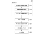
- the control method of the microscope system includes an image acquiring step S21, a stage rotating step S22, an electron microscope image acquiring step S23, a three-dimensional image acquiring step S24, and an automatic imaging step S25, as shown in Fig. 12.
- Fig. 12 is a flowchart showing an example of the procedure of the control method of the microscope system. 12 may be a program that is read and executed by the CPU 65. In this case, the program is stored in the ROM 67 or the RAM 68. Also, a dedicated circuit for performing each step shown in the flowchart of FIG. 12 may be provided in the control unit 65.
- the image acquisition process S21 is a process of acquiring a composite image IM1 shown in FIG. 13, which is obtained based on multiple images of the object O3 captured by the optical microscope 50.
- the composite image IM1 includes a depth synthesis image IM1a and a stitching image IM1b.
- the image acquisition process S21 includes an optical microscope image acquisition process S21a, a depth synthesis image acquisition process S21b, and a stitching image acquisition process S21c.
- the optical microscope image acquisition process S21a, the depth synthesis image acquisition process S21b, and the stitching image acquisition process S21c are executed in this order by the control unit 65 in response to instructions from the user via the input unit 60.
- the optical microscope image acquisition step S21a is a step of acquiring a plurality of optical microscope images by imaging the object O3 using the optical microscope 50 while varying the positional relationship between the focal position and the object in the vertical direction Z.
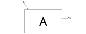
- An example of the optical microscope image G1 of the object O3 acquired in the optical microscope image acquisition step S21a is as shown in Fig. 14.
- the optical microscope image G1 is acquired with the sample holder 11 at position P50 .
- the object O3 in the optical microscope image G1 has an "A" shape.
- the control unit 65 displays the optical microscope image G1 in this orientation on the display surface 56 of the display unit 55.
- the depth stacking image acquisition step S21b is a step of acquiring a depth stacking image IM1a composed of focused pixel information from among a plurality of optical microscope images.
- the stitching image acquisition step S21c is a step of acquiring a stitching image IM1b by stitching a plurality of images together.
- the control unit 65 acquires a stitching image IM1b by stitching a plurality of depth synthesis images IM1a together.
- a stitching image IM1 in which a plurality of depth synthesis images IM1a are stitched together is acquired as a composite image.
- the stage rotation step S22 is a step of rotating the revolver stage 10.
- the control unit 65 rotates the revolver stage 10 around the axis O1 to move the object O3 to a position where the electron microscope 25 can capture an image.
- the focus of the electron microscope 25 may be adjusted using the autofocus function of the electron microscope 25.
- the user can set the focus of the electron microscope 25 to be adjusted using the autofocus function of the electron microscope 25 in the electron microscope image acquisition process S23.
- the control unit 65 calculates the value of the acceleration voltage to be applied to the electron beam EB based on the height H of the lens 52a obtained from the composite image IM1.
- the control unit 65 adjusts the focus of the electron microscope 25 using the autofocus function of the electron microscope 25 within a predetermined range of acceleration voltages including the calculated acceleration voltage value and values near that value.
- the electron microscope image acquisition step S23 includes controlling the focus of the electron microscope 25 by operating the autofocus function within a range specified based on the depth composite image (composite image) IM1a.
- the control unit 65 controls the positional relationship in the vertical direction Z between the object O3 and the focal position of the electron microscope 25 based on the optical positional relationship corresponding to the specified sample holder 11 (for example, the relationship between the focal position of the optical microscope 50 and the acceleration voltage applied to the electron beam EB).Then, the control unit 65 acquires an electron microscope image of the object O3.
- FIG. 15 An example of the electron microscope image G2 of the object O3 acquired in the electron microscope image acquisition step S23 is as shown in Fig. 15.
- the electron microscope image G2 is acquired with the sample holder 11 at position P25 .
- the object O3 in the electron microscope image G2 has a shape obtained by rotating "A" by 180 degrees.
- the control unit 65 displays the electron microscope image G2 in this orientation on the display surface 56 of the display unit 55.
- the solid line arrow A4 in Fig. 15 indicates the direction in which the electron microscope image G2 is scanned on the display surface 56.
- the control unit 65 may display the electron microscope image G2 after rotating it by half on the display surface 56.
- FIG. 16 indicates the direction in which the electron microscope image G2 is scanned on the display surface 56. That is, by reversing the scanning direction from left to right and reversing the scanning order up to down as shown by the arrow A5 in Fig. 16 compared to Fig. 15, the electron microscope image G2 is displayed on the display surface 56 as if it has been rotated by half.
- the three-dimensional image acquisition process S24 is a process for acquiring a three-dimensional image based on pixel information contained in the depth synthesis image (synthetic image) IM1a.
- the control unit 65 executes the three-dimensional image acquisition process S24 and acquires a three-dimensional image showing the three-dimensional shape of the object O3.
- the automatic imaging process S25 is a process for automatically capturing multiple electron microscope images.
- the control unit 65 controls the focus of the electron microscope 25 based on the depth composite image (composite image) IM1a to capture multiple locations of the object O3 corresponding to multiple locations specified in the depth composite image (composite image) IM1a, and obtains multiple electron microscope images by capturing images of the object O3 with the electron microscope 25.
- the focus of the electron microscope 25 can be performed in the same manner as in the electron microscope image acquisition process S23 described above.
- the microscope system 1 of this embodiment includes a revolver stage 10, an electron microscope 25, a second vacuum forming unit 40, and an optical microscope 50. Therefore, the object O3 accommodated in the sample holder 11 of the revolver stage 10 can be observed by both the optical microscope 50 and the electron microscope 25. By rotating the revolver stage 10 around the axis O1, the object O3 can be easily moved between the optical microscope 50 and the electron microscope 25. Furthermore, the sample holder 11 of the revolver stage 10, which is sucked upward by the electron microscope 25, is sucked downward by the second vacuum forming unit 40. Therefore, forces act on the sample holder 11 of the revolver stage 10 from above and below, respectively, preventing the revolver stage 10 from tilting and stabilizing the attitude of the revolver stage 10.
- the sample holder 11 includes a glass support member 13.
- the electron microscope 25 and the second vacuum forming unit 40 respectively suck from above and below the support member 13. Since these suction forces tend to be balanced, the thickness of the support member 13 in the vertical direction Z can be made relatively thin.
- the optical microscope 50 an inverted microscope, an upright microscope, a transmission microscope, or the like can be used.
- the electron microscope 25 can easily maintain the first vacuum region R1 of the sample holder 11 of the revolver stage 10. Therefore, the time required for evacuation for the first vacuum region R1 can be significantly shortened.
- control unit 65 controls the positional relationship between the object O3 and the focal position of the electron microscope 25 based on the corresponding optical positional relationship, and acquires an electron microscope image of the object O3. This makes it possible to easily obtain, for example, an electron microscope image of each object O3 with the focus of each object O3 easily adjusted based on the optical positional relationship corresponding to each sample holder 11.
- the electron microscope 25 and the optical microscope 50 are disposed at positions on either side of the axis O1. This allows the electron microscope 25 and the optical microscope 50 to be disposed around the revolver stage 10 in a well-balanced manner.
- the control unit 65 displays the optical microscope image G1 on the display surface 56, and also displays the electron microscope image G2 after rotating it half way on the display surface 56. Therefore, the orientations of the optical microscope image G1 and the electron microscope image G2 displayed on the display surface 56 can be aligned, making it easier to compare the optical microscope image G1 and the electron microscope image G2 with each other.
- the revolver stage 10 and the electron microscope 25 are fixed to each other by the frame 22.
- electron microscopes are vulnerable to vibrations, but with this configuration, the vibrations occurring in the revolver stage 10 and the electron microscope 25 become the same. Therefore, it is possible to suppress blurring of the electron microscope image G2 acquired by the electron microscope 25.
- the frame 22 can support the rotary motor 20 and the XY stroke stage 21 so as not to collide with each other, and the electron microscope 25 and the optical microscope 50. These components can be held so as not to collide with each other.
- the degree of vacuum in the first vacuum region R1 may be set to a relatively low level. This makes it possible to prevent charge-up from occurring.
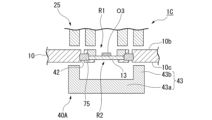
- the microscope system 1B may include a cooling unit 75 using, for example, a Peltier element.
- Peltier element non-contact with revolver stage
- the cooling portion 75 is provided on the upper surface of the bottom wall portion 43 a of the region forming member 43 .
- the cooling unit 75 is disposed below the revolver stage 10 and is spaced apart from the revolver stage 10.
- the cooling unit 75 is disposed in the second vacuum region R2 and cools the sample holder 11A by radiation.
- the cooling unit 75 forms a cryogenic surface in the sample holder 11A, and a cryo (pump) is configured as a vacuum pump that uses this surface to evacuate. The cryo can effectively reduce the pressure around the object O3.
- the cooling unit 75 may be disposed in some of the communication holes 42.
- the cooling unit 75 is preferably in contact with the support member 13. With this configuration, the object O3 can be efficiently cooled by the cooling section 75 via the support member 13.
- the revolver stage 10 may be formed of a magnetic metal, and a magnet may be used instead of the second vacuum forming unit 40.
- the magnet is disposed so as to face the electron microscope 25 via the revolver stage 10.
- the magnet applies a downward external force to the revolver stage 10, thereby preventing the revolver stage 10 from tilting when the first vacuum region R1 is formed.
- an oil immersion lens may be used for the optical microscope.
- the sample holder 11 at position P50 is hereinafter referred to as the first sample holder (first holder) 1150.
- the sample holder 11 at position P25 is hereinafter referred to as the second sample holder (second holder) 1125.
- the first sample holder 1150 and the second sample holder 1125 are formed on the revolver stage 10 with the axis O1 in between.
- an object O3 having an "A" shape (hereinafter also referred to as object O3 50 ) is accommodated in the first sample holder 11 50.
- An object O3 having a shape obtained by rotating a "B" by 180 degrees (hereinafter also referred to as object O3 25 ) is accommodated in the second sample holder 11 25 .
- An electron microscope 80 of this modified example has, in addition to the components of the electron microscope 25, an adjustment unit 81 that changes the range of the object O3 25 scanned by the electron beam EB.
- the microscope system 1C including the electron microscope 80 when the revolver stage 10 is moved in the first horizontal direction X, the objects O3 50 and O3 25 also move in the first horizontal direction X.
- the frame of the optical microscope 50 is at position F 50a , and the object O3 50 is biased toward the +X side of the first horizontal direction X (the second side opposite to the first side in the intersecting direction) with respect to the frame of the optical microscope 50.
- the frame of the electron microscope 80 is at position F 80a , and the electron beam EB changed by the adjustment unit 81 is defined as electron beam EB a .
- the intersecting direction may be the second horizontal direction Y.
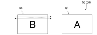
- the control unit 65 When the revolver stage 10 is moved to the -X side of the first horizontal direction X relative to the electron microscope 80 and the optical microscope 50 by the XY stroke stage 21 while the optical microscope 50 is acquiring an optical microscope image G5 of the object O3 50 held in the first sample holder 11 50, the control unit 65 performs control as follows. At this time, the frame of the optical microscope 50 is at a relative position F 50b . The frame of the electron microscope 80 is at a relative position F 80b . The electron beam EB a has not yet been changed within the range. That is, while the control unit 65 acquires an electron microscope image G6 of the object O3 25 accommodated in the second sample holder 11 25 by the electron microscope 80, the adjustment unit 81 moves the range to the +X side of the first horizontal direction X.
- the object O3 25 comes to the center of the frame of the electron microscope 80.
- An optical microscope image G5 and an electron microscope image G6 displayed on the display surface 56 of the display unit 55 are shown in FIG. Therefore, the object O3 25 can be positioned at the center of the frame of the electron microscope 80 even if the revolver stage 10 is moved along the horizontal plane.
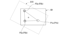
- the optical microscope image G9 shown in Fig. 21 and the electron microscope image G10 shown in Fig. 22 are aligned as follows. That is, as shown in FIG. 21, three points P1a, P2a, and P3a corresponding to three parts of an object O3 serving as a landmark are selected in an optical microscope image G9. 22, three points P1b, P2b, and P3b corresponding to the three points P1a, P2a, and P3a of the object O3 are selected in the electron microscope image G10. The order in which the three points P1b, P2b, and P3b are selected must be the same as the order in which the corresponding three points P1a, P2a, and P3a are selected.
- the control unit 65 adjusts the electron microscope image G10, for example, by changing the magnification and shifting and rotating the electron microscope image G10, so that points P1b, P2b, and P3b overlap with points P1a, P2a, and P3a, respectively.
- the method of aligning the images G9 and G10 at least one of the optical microscope image G9 and the electron microscope image G10 is adjusted.
- the microscope system 2 of this embodiment includes a linear stage 90, a drive unit (not shown), an electron microscope 105, an optical microscope 110, and a control unit (not shown).
- the linear stage 90 has a sample holder (holding stage) 91 and a pair of rails 96 . 2-1-2-2. Sample Holder 2-1-2-2-1. Single Shot Type
- the sample holder 91 moves back and forth between the electron microscope 105 and the optical microscope 110 and other locations.
- the sample holder 91 has a main body 92 and a pair of protrusions 93.
- the main body 92 is formed in a flat plate shape from a light-transmitting material such as glass.
- the main body 92 is disposed so that the thickness direction of the main body 92 is aligned with the vertical direction Z.
- the conductive transparent film may be provided on the upper surface of the main body 92.
- the upper surface of the main body 92 is formed with a receiving portion 92a, which is a recess for receiving the object O3.
- the protrusions 93 are provided on a side surface of the main body 92 facing the second horizontal direction Y.
- the pair of protrusions 93 extend along the first horizontal direction X.
- the pair of protrusions 93 are provided over the entire length of the main body 92 in the first horizontal direction X.
- the serial type sample holder may be configured to be even longer in the first horizontal direction X.
- the body of the sample holder may have a plurality of storage sections formed along the first horizontal direction X (the pair of rails 96). The plurality of storage sections are arranged at intervals from each other in the first horizontal direction X.
- Each rail 96 has a rail body 97 and a holding portion 98.
- the rail main bodies 97 extend in the first horizontal direction X.
- the rail main bodies 97 of the pair of rails 96 are disposed in the second horizontal direction Y at a distance from each other.
- the holding portion 98 is attached to an upper portion of the rail main body 97, and can slide in the first horizontal direction X relative to the rail main body 97.
- a groove 98a is formed in a side surface of the holding portion 98 that faces the inside of the pair of rail main bodies 97.
- the groove 98a penetrates the holding portion 98 in the first horizontal direction X.
- the grooves 98a of the pair of rails 96 face each other in the second horizontal direction Y.
- the sample holder 91 is attached to the pair of rails 96 by fitting the pair of protrusions 93 of the sample holder 91 into the grooves 98a of the pair of rails 96.
- the driving unit includes, for example, a ball screw and a driving motor.
- the ball screw is attached to the holding portion 98.
- the drive motor rotates the ball screw about its axis, thereby moving the holding portion 98 in the first horizontal direction X relative to the rail main body 97.
- the driving unit may be configured to move the sample holder 91 not only in the first horizontal direction X, but also in the second horizontal direction Y and the vertical direction Z.
- the electron microscope 105 is not particularly limited and may be configured similarly to the electron microscope 25.
- the electron microscope 105 is for observing the object O3.
- the electron microscope 105 is disposed above the sample holder 91.
- the electron microscope 105 observes an object O3 on a central axis O7 of the electron microscope 105, which extends in the vertical direction Z.
- the electron microscope 105 is disposed such that the central axis O7 passes through a space S3 formed between a pair of rails 96.
- the pair of rails 96 constitute a space forming portion 100 that forms a space S3 on the central axis O7.
- the electron microscope 105 may be equipped with the energy dispersive X-ray analyzer.
- a local vacuum region is formed between the sample holder 91 and the electron microscope 105.
- the electron microscope 105 has a shutter so that the degree of vacuum created by the local vacuum region is maintained even when the sample holder 91 moves from the central axis O7 in the first horizontal direction X.
- the shutter closes the portion of the local vacuum region that was previously closed by the sample holder 91.
- the shutter is in contact with the sample holder 91 when the sample holder 91 moves along the central axis O7. In this case, the vibrations generated in the sample holder 91 and the vibrations generated in the electron microscope 105 become the same. Therefore, it is possible to suppress the electron microscope image acquired by the electron microscope 105 from being blurred due to the vibrations.
- the optical microscope 110 is not particularly limited and may be configured similarly to the optical microscope 50.
- the optical microscope 110 observes the object O3 using visible light.
- the optical microscope 110 is disposed on the central axis O7 and below the sample holder 91.
- control unit is configured in the same manner as the control unit 65 described above.
- the object O3 can be simultaneously observed by the electron microscope 105 and the optical microscope 110. Furthermore, since the space S3 is formed between the pair of rails 96, the object O3 can be observed by the optical microscope 110 from below the sample holder 91 using the space S3. When a plurality of containers are formed in the sample holder, a plurality of objects O3 can be efficiently observed by storing the objects O3 in the plurality of containers, respectively.
- the microscope system 2 includes a space forming unit 100 that forms the space S3. Therefore, the object O3 can be observed from below the sample holder 91 using the optical microscope 110 using the space S3.
- the optical microscope 110 is arranged at a position shifted in the first horizontal direction X with respect to the central axis O7 of the electron microscope 105 in the microscope system 2 of this embodiment.
- the position of the sample holder 91 for observation with the optical microscope 110 and the position of the sample holder 91 for observation with the electron microscope 105 are different in the first horizontal direction X.
- the microscope system 2A of this modified example can achieve the same effects as the microscope system 2 of this embodiment.
- the microscope systems 1 , 1A, 1B, 1C, 2 , and 2A may not include the rotation motor 20 , the frame 22 , the display unit 55 , the input unit 60 , and the control unit 65 .
- the present invention provides microscope systems 1, 1A, 1B, 1C, 2, and 2A in which the posture of the revolver stage 10 and 10A is stabilized. This has great industrial applicability.
Landscapes
- Chemical & Material Sciences (AREA)
- Analytical Chemistry (AREA)
- Microscoopes, Condenser (AREA)
Abstract
この顕微鏡システムは、対象物を収容するホルダが設けられた第1面を有するステージと、ホルダに収容された対象物に電子ビームを照射して、対象物の情報を取得する電子顕微鏡と、ステージの第1面と対向可能に配置され、第1面の一部に局所的に第1真空領域を形成する第1真空形成部と、ステージの第2面と対向可能に配置され、ステージを挟んで第1真空形成部の反対側で、第2面の一部に局所的に第2真空領域を形成する第2真空形成部と、を備え、電子顕微鏡は、第1真空領域、及び第2真空領域を形成した状態で、ホルダ内の対象物に、第1真空領域を介して電子ビームを照射する。
Description
本発明は、顕微鏡システムに関する。
顕微鏡システムが知られている。例えば、特許文献1には、走査型電子顕微鏡が記載されている。
本発明の顕微鏡システムの第1の態様は、対象物を収容するホルダが設けられた第1面を有するステージと、前記ホルダに収容された前記対象物に電子ビームを照射して、前記対象物の情報を取得する電子顕微鏡と、前記ステージの前記第1面と対向可能に配置され、前記第1面の一部に局所的に第1真空領域を形成する第1真空形成部と、前記ステージの第2面と対向可能に配置され、前記ステージを挟んで前記第1真空形成部の反対側で、前記第2面の一部に局所的に第2真空領域を形成する第2真空形成部と、を備え、前記電子顕微鏡は、前記第1真空領域、及び前記第2真空領域を形成した状態で、前記ホルダ内の前記対象物に、前記第1真空領域を介して前記電子ビームを照射する。
(1.第1実施形態)
1-1.基本構成
1-1-1.システム全体の概要
以下、図面を参照しながら、実施形態に係る顕微鏡システムについて説明する。
なお、実施形態は、以下に示された技術的思想の範囲内で任意に変更可能である。また、図面においては、各構成をわかりやすくするために、各構造における縮尺及び数等を、実際の構造における縮尺及び数等と異ならせる場合がある。
1-1.基本構成
1-1-1.システム全体の概要
以下、図面を参照しながら、実施形態に係る顕微鏡システムについて説明する。
なお、実施形態は、以下に示された技術的思想の範囲内で任意に変更可能である。また、図面においては、各構成をわかりやすくするために、各構造における縮尺及び数等を、実際の構造における縮尺及び数等と異ならせる場合がある。
また、図面には適宜XYZ直交座標系を示し、このXYZ直交座標系を参照しつつ各部の位置関係について説明する。X軸と平行な方向を「第1水平方向X」と記載し、Y軸と平行な方向を「第2水平方向Y」と記載し、Z軸と平行な方向を「鉛直方向Z」と記載する。第1水平方向Xと第2水平方向Yと鉛直方向Zとは、互いに直交する方向である。鉛直方向ZのうちZ軸の矢印が向く正の側(+Z側)を「上方」または「上側」と記載し、鉛直方向ZのうちZ軸の矢印が向く側と逆側の負の側(-Z側)を「下方」または「下側」と記載する。鉛直方向Zは、高さ方向である。
図1は、本実施形態の顕微鏡システム1を模式的に示す概略構成図である。本実施形態において顕微鏡システム1は、例えば大気圧中に配置される。
図1に示すように、顕微鏡システム1は、リボルバーステージ(ステージ)10と、回転モータ(空間形成部)20と、フレーム22と、電子顕微鏡25と、第2真空形成部40と、光学顕微鏡(光学機器)50と、表示部55と、入力部60と、制御部65と、を備える。
電子顕微鏡25と光学顕微鏡50とは、例えば、第1水平方向Xに並んで配置される。図1の表示面において、電子顕微鏡25は、例えば、光学顕微鏡50の左側に配置される。
図1に示すように、顕微鏡システム1は、リボルバーステージ(ステージ)10と、回転モータ(空間形成部)20と、フレーム22と、電子顕微鏡25と、第2真空形成部40と、光学顕微鏡(光学機器)50と、表示部55と、入力部60と、制御部65と、を備える。
電子顕微鏡25と光学顕微鏡50とは、例えば、第1水平方向Xに並んで配置される。図1の表示面において、電子顕微鏡25は、例えば、光学顕微鏡50の左側に配置される。
1-1-2.リボルバーステージ
図1及び図2に示すように、本実施形態では、リボルバーステージ10はXY平面において円板状である。リボルバーステージ10は、自身の軸線(回転軸)O1が鉛直方向Zに沿うように配置されている。第1水平方向X及び第2水平方向Yは、軸線O1に直交(交差)する交差方向である。
リボルバーステージ10は、上面である第1面10bと、下面である第2面10cと、を有する。第1面10b及びる第2面10cは、それぞれ円形状である。
例えば、リボルバーステージ10は、真鍮、ステンレス等の金属で形成されている。
以下では、リボルバーステージ10の周方向を、単に周方向と言う。
図1及び図2に示すように、本実施形態では、リボルバーステージ10はXY平面において円板状である。リボルバーステージ10は、自身の軸線(回転軸)O1が鉛直方向Zに沿うように配置されている。第1水平方向X及び第2水平方向Yは、軸線O1に直交(交差)する交差方向である。
リボルバーステージ10は、上面である第1面10bと、下面である第2面10cと、を有する。第1面10b及びる第2面10cは、それぞれ円形状である。
例えば、リボルバーステージ10は、真鍮、ステンレス等の金属で形成されている。
以下では、リボルバーステージ10の周方向を、単に周方向と言う。
1-1-2-1.サンプルホルダ
リボルバーステージ10の第1面10bには、対象物O3を収容するサンプルホルダ(ホルダ)11が形成されている。なお、サンプルホルダ11に収容されている対象物O3を「サンプルホルダ11内の対象物O3」と表現しても良い。サンプルホルダ11は、リボルバーステージ10の第2面10cに達している。
リボルバーステージ10には、軸線O1回りにサンプルホルダ11が複数形成されている。リボルバーステージ10には、サンプルホルダ11が軸線O1回りに互いに間隔を空けて複数形成されている。
なお、制御部65は、リボルバーステージ10を駆動する回転モータ20に設けられた回転エンコーダ、又はセンサ等で、各サンプルホルダ11の位置を認識することができる。リボルバーステージ10に形成されるサンプルホルダ11の数は、1つでもよい。
1-1-2-1-1.シャトルタイプ
図3に示すように、サンプルホルダ11は、収容孔12と、支持部材(シャトル)13と、保持部材14と、付勢部材15と、を有する。
収容孔12は、リボルバーステージ10を、リボルバーステージ10の厚さ方向(以下では、単に厚さ方向とも言う)に貫通している。厚さ方向は、鉛直方向Zに沿う。なお、厚さ方向は、鉛直方向Zに対して傾斜していてもよい。
収容孔12は、小径孔(照射孔)12aと、中径孔12bと、大径孔12cと、を有する。小径孔12a、中径孔12b、及び大径孔12cは、それぞれ円筒状であり、互いに同軸に配置されている。小径孔12a、中径孔12b、及び大径孔12cの軸線は、それぞれ鉛直方向Zに沿う。
図3に示すように、サンプルホルダ11は、収容孔12と、支持部材(シャトル)13と、保持部材14と、付勢部材15と、を有する。
収容孔12は、リボルバーステージ10を、リボルバーステージ10の厚さ方向(以下では、単に厚さ方向とも言う)に貫通している。厚さ方向は、鉛直方向Zに沿う。なお、厚さ方向は、鉛直方向Zに対して傾斜していてもよい。
収容孔12は、小径孔(照射孔)12aと、中径孔12bと、大径孔12cと、を有する。小径孔12a、中径孔12b、及び大径孔12cは、それぞれ円筒状であり、互いに同軸に配置されている。小径孔12a、中径孔12b、及び大径孔12cの軸線は、それぞれ鉛直方向Zに沿う。
小径孔12aは、リボルバーステージ10の上面に開口している。
中径孔12bの外径は、小径孔12aの外径よりも大きい。中径孔12bは、小径孔12aよりも下方に配置され、小径孔12aに連なっている。
大径孔12cの外径は、中径孔12bの外径よりも大きい。大径孔12cは、中径孔12bよりも下方に配置され、中径孔12bに連なっている。大径孔12cは、リボルバーステージ10の下面に開口している。
リボルバーステージ10において、平面視で大径孔12cの外周縁の内側に位置する部分が、封止板10aに該当する。封止板10aは、円環状である。封止板10aの上面は、平坦である。
本実施形態では、封止板10aはリボルバーステージ10と一体であるが、封止板はリボルバーステージ10と別体でもよい。この場合、封止板は、サンプルホルダの一部を構成する。
図3から図5に示すように、支持部材13は、円板状である。支持部材13は、ガラス等の光を透過する材料で形成されている。支持部材13は、可視光線を透過する。図3に示すように、支持部材13の上端部は、収容孔12の中径孔12b内に配置されている。支持部材13は、収容孔12の中径孔12b及び大径孔12c内に配置されている。支持部材13の上面は、対象物O3を支持する。
なお、支持部材13の上面には、ITO(酸化インジウムスズ)、TiO2(二酸化チタン)等で形成された導電性の透明膜を設けてもよい。このように構成することにより、電子顕微鏡25による観察の際に、対象物O3及びその周辺がチャージアップ(帯電)して対象物O3が観察し難くなるのが抑制される。さらに、対象物O3に付着した2次電子を取り除きつつ、電子顕微鏡画像の劣化を抑制することができる。
なお、支持部材13の上面には、ITO(酸化インジウムスズ)、TiO2(二酸化チタン)等で形成された導電性の透明膜を設けてもよい。このように構成することにより、電子顕微鏡25による観察の際に、対象物O3及びその周辺がチャージアップ(帯電)して対象物O3が観察し難くなるのが抑制される。さらに、対象物O3に付着した2次電子を取り除きつつ、電子顕微鏡画像の劣化を抑制することができる。
図3から図5に示すように、支持部材13の上面には、環状の封止部材18が配置される。封止部材18は、ゴム等の弾性を有する材料で形成されている。例えば、封止部材18には、Oリングが用いられる。封止部材18は、支持部材13と同軸に配置されている。
図3に示すように、封止部材18は、リボルバーステージ10における中径孔12bを区画する下面に、この下面よりも下方から接触している。
図3に示すように、封止部材18は、リボルバーステージ10における中径孔12bを区画する下面に、この下面よりも下方から接触している。
保持部材14は、円環状である。保持部材14の内周縁は、支持部材13の外周縁を、この外周縁の下方から支持している。保持部材14の内周縁は、支持部材13の外周縁に固定されている。
例えば、付勢部材15は、つる巻きバネである。付勢部材15の第1端部は、保持部材14の上面における径方向外側の部分に固定されている。付勢部材15における第1端部とは反対の第2端部は、リボルバーステージ10における大径孔12cを区画する下面に固定されている。付勢部材15は、リボルバーステージ10に対して保持部材14を上方に向かって付勢する。このため、封止部材18は、リボルバーステージ10と支持部材13との間で、鉛直方向Zに挟まれる。封止部材18は、リボルバーステージ10と支持部材13との間を気密に封止する。
例えば、付勢部材15は、つる巻きバネである。付勢部材15の第1端部は、保持部材14の上面における径方向外側の部分に固定されている。付勢部材15における第1端部とは反対の第2端部は、リボルバーステージ10における大径孔12cを区画する下面に固定されている。付勢部材15は、リボルバーステージ10に対して保持部材14を上方に向かって付勢する。このため、封止部材18は、リボルバーステージ10と支持部材13との間で、鉛直方向Zに挟まれる。封止部材18は、リボルバーステージ10と支持部材13との間を気密に封止する。
サンプルホルダ11は、付勢部材15を複数有する。複数の付勢部材15は、保持部材14の軸線回りに、互いに間隔を空けて配置されている。支持部材13は、リボルバーステージ10における収容孔12の周縁部に、保持部材14及び付勢部材15を介して設けられている。
なお、サンプルホルダ11は、保持部材14及び付勢部材15を有さなくてもよい。
なお、サンプルホルダ11は、保持部材14及び付勢部材15を有さなくてもよい。
以上のように構成されたリボルバーステージ10は、回転モータ20により、軸線O1回りに回転可能に支持されている。
リボルバーステージ10は、軸線O1回りのいずれの向きにも回転するステージである。
図1に示すように、電子顕微鏡25及び光学顕微鏡50は、軸線O1を、軸線O1に交差する方向に挟む位置にそれぞれ配置されている。なお、電子顕微鏡25及び光学顕微鏡50は、軸線O1を、軸線O1に交差する方向に挟まない位置に配置されてもよい。
リボルバーステージ10は、軸線O1回りのいずれの向きにも回転するステージである。
図1に示すように、電子顕微鏡25及び光学顕微鏡50は、軸線O1を、軸線O1に交差する方向に挟む位置にそれぞれ配置されている。なお、電子顕微鏡25及び光学顕微鏡50は、軸線O1を、軸線O1に交差する方向に挟まない位置に配置されてもよい。
図6に示すように、複数の付勢部材15の付勢力に抗して支持部材13を下方に移動させると、封止部材18がリボルバーステージ10から下方に離間する。このとき、リボルバーステージ10の下方から、支持部材13上に対象物O3を乗せやすくなる。支持部材13上の対象物O3を交換しやすくなる。
1-1-2-1-2.非シャトルタイプ
本実施形態では、サンプルホルダ11は、収容孔12と、支持部材(シャトル)13と、保持部材14と、付勢部材15と、を有していた。しかし、これに限らず、サンプルホルダ11は、単なる窪み(XZ平面、又はYZ平面から見て凹型)であっても良い。この場合、窪みの底面がガラス等の光を透過する材料で形成されている。この場合、サンプルホルダ11の形状をシンプルにすることができる。
本実施形態では、サンプルホルダ11は、収容孔12と、支持部材(シャトル)13と、保持部材14と、付勢部材15と、を有していた。しかし、これに限らず、サンプルホルダ11は、単なる窪み(XZ平面、又はYZ平面から見て凹型)であっても良い。この場合、窪みの底面がガラス等の光を透過する材料で形成されている。この場合、サンプルホルダ11の形状をシンプルにすることができる。
1-1-2-2.アライメントマーク
1-1-2-2-1.サンプルホルダ間にアライメントマークを設ける
リボルバーステージ10における、周方向に隣り合うサンプルホルダ11の間に位置する部分に、複数のサンプルホルダ11同士を区別するためのアライメントマークを設けてもよい。アライメントマークとしては、リボルバーステージ10の上面から突出又は凹んだ形状を用いることができる。
このように構成することにより、ユーザが手動でアライメントマークを設ける必要が無くなり、顕微鏡システム1の操作を容易に行うことができる。
1-1-2-2-1.サンプルホルダ間にアライメントマークを設ける
リボルバーステージ10における、周方向に隣り合うサンプルホルダ11の間に位置する部分に、複数のサンプルホルダ11同士を区別するためのアライメントマークを設けてもよい。アライメントマークとしては、リボルバーステージ10の上面から突出又は凹んだ形状を用いることができる。
このように構成することにより、ユーザが手動でアライメントマークを設ける必要が無くなり、顕微鏡システム1の操作を容易に行うことができる。
1-1-2-2-2.アライメント用の対象物をサンプルホルダに入れる。
リボルバーステージ10にアライメントマークを設ける代わりに、複数のサンプルホルダ11同士を区別するための対象物O3を、サンプルホルダ11に収容してもよい。この場合、例えば、複数のサンプルホルダ11のうち、所定のサンプルホルダ11に収容する対象物O3だけに、アライメントマークを設ける。
このように構成することにより、リボルバーステージ10にアライメントマークを設ける必要がない。このため、「1-1-2-2-1.サンプルホルダ間にアライメントマークを設ける」場合と比較して、リボルバーステージ10により多くのサンプルホルダ11を設けることができる。
リボルバーステージ10にアライメントマークを設ける代わりに、複数のサンプルホルダ11同士を区別するための対象物O3を、サンプルホルダ11に収容してもよい。この場合、例えば、複数のサンプルホルダ11のうち、所定のサンプルホルダ11に収容する対象物O3だけに、アライメントマークを設ける。
このように構成することにより、リボルバーステージ10にアライメントマークを設ける必要がない。このため、「1-1-2-2-1.サンプルホルダ間にアライメントマークを設ける」場合と比較して、リボルバーステージ10により多くのサンプルホルダ11を設けることができる。
1-1-3.回転モータ
図1に示すように、例えば回転モータ20は、リボルバーステージ10よりも上方における軸線O1上に配置される。回転モータ20の駆動軸(不図示)は、リボルバーステージ10に固定されている。回転モータ20は、リボルバーステージ10を軸線O1回りに回転させる。すなわち、回転モータ20は、リボルバーステージ10を軸線O1回りに移動させる。
回転モータ20は、図示しない回転エンコーダを備えている。回転エンコーダは、駆動軸を介して、リボルバーステージ10の回転数、及び1回転(360°)内の回転角度を検出する。例えば、回転エンコーダは、リボルバーステージ10が、回転数として5回転し、回転角として120°回転したと検出する。
なお、回転モータ20は、リボルバーステージ10を鉛直方向Zに移動させるように構成されてもよい。回転モータ20は、リボルバーステージ10よりも下方における軸線O1上に配置されてもよい。
1-1-4.XYストロークステージ
顕微鏡システム1は、XYストロークステージ(移動部)21を備えることが好ましい。XYストロークステージ21は、回転モータ20を第1水平方向X及び第2水平方向Yにそれぞれ移動させる。XYストロークステージ21は、電子顕微鏡25及び光学顕微鏡50に対して、リボルバーステージ10を第1水平方向X及び第2水平方向Yに相対的に移動させる。XYストロークステージ21は、第1面10b及び第2面10cに平行な平面内でリボルバーステージ10を移動させる。
なお、XYストロークステージ21は、回転モータ20を鉛直方向Zに移動させるように構成されてもよい。
また、回転モータ20とXYストロークステージ21とを合わせて移動ステージ23と記載しても良い(図1参照)。移動ステージ23は、リボルバーステージ10を、軸線O1回りに回転させる。
1-1-5.フレーム
フレーム22は、顕微鏡システム1の筐体である。例えば、フレーム22は、連結部材22aと、中央支持部材22bと、端部支持部材22c,22dと、を有する。
連結部材22aは、第1水平方向Xに沿って延びている。中央支持部材22bは、連結部材22aにおける第1水平方向Xの中央部から下方に延び、XYストロークステージ21に固定されている。端部支持部材22cは、連結部材22aの第1端部から下方に延び、電子顕微鏡25に固定されている。端部支持部材22dは、連結部材22aにおける第1端部とは反対側の第2端部から下方に延び、光学顕微鏡50に固定されている。フレーム22は、鋼材等で形成されている。
フレーム22は、顕微鏡システム1の筐体である。例えば、フレーム22は、連結部材22aと、中央支持部材22bと、端部支持部材22c,22dと、を有する。
連結部材22aは、第1水平方向Xに沿って延びている。中央支持部材22bは、連結部材22aにおける第1水平方向Xの中央部から下方に延び、XYストロークステージ21に固定されている。端部支持部材22cは、連結部材22aの第1端部から下方に延び、電子顕微鏡25に固定されている。端部支持部材22dは、連結部材22aにおける第1端部とは反対側の第2端部から下方に延び、光学顕微鏡50に固定されている。フレーム22は、鋼材等で形成されている。
以上のように、フレーム22には、XYストロークステージ21、電子顕微鏡25、及び光学顕微鏡50が固定されている。すなわち、リボルバーステージ10、回転モータ20、XYストロークステージ21、フレーム22、電子顕微鏡25の順で互いに接続されている。フレーム22は、移動ステージ23及び電子顕微鏡25を固定する。
なお、光学顕微鏡50はフレーム22に固定されなくてもよい。
連結部材22aにおける中央部と第2端部の間に、鋼材よりも弾性率が小さい材料で形成された弾性部材22eが設けられてもよい。このように構成することにより、回転モータ20に生じる振動を弾性部材22eで吸収し、光学顕微鏡50に伝達しないようにすることができる。
なお、光学顕微鏡50はフレーム22に固定されなくてもよい。
連結部材22aにおける中央部と第2端部の間に、鋼材よりも弾性率が小さい材料で形成された弾性部材22eが設けられてもよい。このように構成することにより、回転モータ20に生じる振動を弾性部材22eで吸収し、光学顕微鏡50に伝達しないようにすることができる。
1-1-6.電子顕微鏡
電子顕微鏡25の種類は、特に限定されない。電子顕微鏡25は、例えば、走査型電子顕微鏡(Scanning Electron Microscope;SEM)である。なお、電子顕微鏡25は、透過型電子顕微鏡(Transmission Electron Microscope;TEM)であってもよい。
なお、電子顕微鏡25に、エネルギー分散型X線分析装置(EDS)を搭載してもよい。そして、エネルギー分散型X線分析装置が、電子線にて励起された特性X線を検出することにより、対象物O3の含有元素、及びその組成比を特定してもよい。
図1に示すように、電子顕微鏡25は、リボルバーステージ10よりも上方(厚さ方向の第1側)に配置されている。なお、リボルバーステージ10に対して電子顕微鏡25が配置される向きは、下方、水平面に沿う向きであってもよい。
電子顕微鏡25は、筐体26と、光源部27と、光電部28と、電子レンズ29と、走査部(不図示)と、排気装置30と、を有する。
筐体26は、例えば、鉛直方向Zに延びる円筒状である。筐体26の内部には、電子ビームEBが通る電子ビーム路26aが設けられる。電子ビームEBの光軸方向と鉛直方向Zとは、ほぼ平行である。電子ビーム路26aは、鉛直方向Zに延びる。
電子ビーム路26aの上端部には、光電部28が設けられる。筐体26の下端部には、下方を向く射出開口(照射開口)26cが設けられる。
電子ビーム路26aの上端部には、光電部28が設けられる。筐体26の下端部には、下方を向く射出開口(照射開口)26cが設けられる。
光源部27は、筐体26の上端面に固定される。光源部27は、筐体26の内部空間に光を射出可能である。光源部27から筐体26の内部空間に射出された光は、筐体26内に設けられた光電部28に照射される。
光電部28は、光電効果によって、光が照射されることで電子ビームEBを射出する。本実施形態において光電部28は、上方から光源部27の光が入射されることで、下方に電子ビームEBを射出する。光電部28から下方に射出された電子ビームEBは、電子ビーム路26aを通って、射出開口26cから対象物O3に向けて下方に射出される。射出開口26cは、対象物O3に向かって電子ビームEBが照射される、電子顕微鏡25の中心軸線O5上に形成されている。中心軸線Oは、鉛直方向Zに延びる。
電子レンズ29は、筐体26の内部に配置される。電子レンズ29は、光電部28よりも下方において、電子ビーム路26aを囲んで配置される。電子レンズ29は、光電部28から射出された電子ビームEBを収束させて射出開口26cに導く。本実施形態において電子レンズ29は、永久磁石を用いた磁界レンズである。
なお、電子レンズ29は、永久磁石を用いない磁界レンズであってもよいし、静電レンズであってもよい。
なお、電子レンズ29は、永久磁石を用いない磁界レンズであってもよいし、静電レンズであってもよい。
電子レンズ29として永久磁石を用いた磁界レンズを用いた場合、電子ビームEBに印加される加速電圧と電子顕微鏡25の焦点位置との関係が線形になりやすい。電子ビームEBに印加される加速電圧とは、筐体26内において光電部28よりも下方に配置された図示しない引出電極と光電部28との間に印加される電圧である。
加速電圧が大きくなる程、電子顕微鏡25の焦点位置が下方になる。言い換えれば、加速電圧が大きくなる程、電子顕微鏡25の焦点深度が深くなる。
加速電圧が大きくなる程、電子顕微鏡25の焦点位置が下方になる。言い換えれば、加速電圧が大きくなる程、電子顕微鏡25の焦点深度が深くなる。
電子顕微鏡25は、図示しない走査部を有する。走査部は、電子ビームEBを第1水平方向X及び第2水平方向Yにそれぞれ走査させる。
排気装置30は、ノズル部材33と、第1ポンプ34と、第2ポンプ35と、を有する。ノズル部材33は、電子顕微鏡25の中心軸線O5回りに筐体26を囲む環状である。本実施形態において中心軸線O5は、電子ビーム路26aの中心を通る。
図1及び図3に示すように、ノズル部材33は、下方に突出する突出部33aを有する。突出部33aは、中心軸線O5回りに筐体26の下端面26bを囲んでいる。ノズル部材33には、第1吸気流路33bが設けられる。第1吸気流路33bは、例えば、複数設けられる。第1吸気流路33bは、突出部33aの下端面に開口する吸気開口(吸引開口)33cを有する。複数の第1吸気流路33bにおける吸気開口33cは、例えば、突出部33aの下端面において中心軸線O5回りの周方向に、互いに間隔を空けて配置される。複数の吸気開口33cは、中心軸線O5回りに、射出開口26cを囲うように配置されている。
前記リボルバーステージ10の封止板10aの上面は、吸気開口33cに対向する。前記封止板10aの小径孔12aは、電子顕微鏡25の封止板10aにおける射出開口26cに対向する部分に形成されている。封止板10aにおける電子顕微鏡25の射出開口26cに対向する部分には、小径孔12aが形成されている。
前記リボルバーステージ10の封止板10aの上面は、吸気開口33cに対向する。前記封止板10aの小径孔12aは、電子顕微鏡25の封止板10aにおける射出開口26cに対向する部分に形成されている。封止板10aにおける電子顕微鏡25の射出開口26cに対向する部分には、小径孔12aが形成されている。
第1ポンプ34及び第2ポンプ35は、真空ポンプである。なお、第1ポンプ34及び第1吸気流路33bで、第1真空形成部37を構成する。
第1ポンプ34及び第2ポンプ35として用いられる真空ポンプの種類は、特に限定されない。第1ポンプ34は、例えば、油拡散ポンプである。第2ポンプ35は、例えば、油拡散ポンプとターボ分子ポンプとを組み合わせたポンプである。
第1ポンプ34及び第2ポンプ35として用いられる真空ポンプの種類は、特に限定されない。第1ポンプ34は、例えば、油拡散ポンプである。第2ポンプ35は、例えば、油拡散ポンプとターボ分子ポンプとを組み合わせたポンプである。
図1に示すように、第1ポンプ34は、第1吸気流路33bに接続される。第1ポンプ34によって、吸気開口33cから第1吸気流路33b内に空気が吸引される。
なお、第1吸気流路33b内には、突出部33aの内側の空気の少なくとも一部が吸引されてもよい。
なお、第1吸気流路33b内には、突出部33aの内側の空気の少なくとも一部が吸引されてもよい。
第2ポンプ35は、第2吸気流路33dを介して、電子ビーム路26a内の空気を吸引可能である。第2吸気流路33dは、例えば、電子ビーム路26a内の上側の端部に繋がる。第2吸気流路33d内には、電子ビーム路26a内の空気が吸引される。なお、第2吸気流路33d内には、突出部33aの内側の空気の少なくとも一部が吸引されてもよい。
ノズル部材33の突出部33aの下端面とリボルバーステージ10の上面との間には、わずかな隙間が形成されている。
ノズル部材33の突出部33aの下端面とリボルバーステージ10の上面との間には、わずかな隙間が形成されている。
第1ポンプ34と第2ポンプ35とによって空気を吸引することによって、電子ビーム路26a内、突出部33a内、及び突出部33aの下端面とリボルバーステージ10との鉛直方向Zの間を真空にすることができる。吸気開口33cは、突出部33aの下端面とリボルバーステージ10のサンプルホルダ11との間である第1真空領域R1の空気を吸引する。すなわち、電子顕微鏡25には、第1真空領域R1による、いわゆる局部真空領域が形成される。第1真空領域R1は、リボルバーステージ10の第1面10bの一部に局所的に形成される。第1真空形成部37は、リボルバーステージ10の第1面10bと対向可能に配置され、第1真空領域R1を形成する。
顕微鏡システム1では、リボルバーステージ10が軸線O1回りに回転しても、局部真空領域が維持されやすい。
顕微鏡システム1では、リボルバーステージ10が軸線O1回りに回転しても、局部真空領域が維持されやすい。
第1真空領域R1が形成されることにより、リボルバーステージ10における第1真空領域R1に接触する部分が、上方に向かって吸引される。電子顕微鏡25は、サンプルホルダ11よりも上方に第1真空領域R1を形成しつつ、対象物O3を観察する。電子顕微鏡25は、中心軸線O5上の対象物O3を観察し、対象物O3の像である電子顕微鏡画像を取得する。電子顕微鏡25は、サンプルホルダ11に収容された対象物O3に電子ビームEBを照射して、対象物O3の情報を取得する。
図2において、例えば、位置(第2位置)P50が、光学顕微鏡50で観察するためのサンプルホルダ11の位置である。位置(第1位置)P25が、電子顕微鏡25で観察するためのサンプルホルダ11の位置である。位置P25及び位置P50はそれぞれ、軸線O1回りに異なる位置に配置される。位置P50は、位置P25を軸線O1回りに180°(半回転)回転させた位置である。
リボルバーステージ10は、サンプルホルダ11を少なくとも位置P25及び位置P50に移動させるように可動である。リボルバーステージ10は、軸線O1を中心に回転する。
例えば、位置P50において「A」形状の対象物O3は、位置P25において、「A」を180°回転させた形状となる。
リボルバーステージ10は、サンプルホルダ11を少なくとも位置P25及び位置P50に移動させるように可動である。リボルバーステージ10は、軸線O1を中心に回転する。
例えば、位置P50において「A」形状の対象物O3は、位置P25において、「A」を180°回転させた形状となる。
1-1-7.第2真空形成部によるヴァキュームキャンセル機構
1-1-7-1.真空形成部(タイプ1)
本実施形態では、第2真空形成部40は、排気装置30の第1ポンプ34と同様に構成されている。図1に示すように、リボルバーステージ10及び電子顕微鏡25よりも下方であって、空間S1に配置されている。第2真空形成部40は、リボルバーステージ10の第2面10cと対向可能に配置される。
1-1-7-1.真空形成部(タイプ1)
本実施形態では、第2真空形成部40は、排気装置30の第1ポンプ34と同様に構成されている。図1に示すように、リボルバーステージ10及び電子顕微鏡25よりも下方であって、空間S1に配置されている。第2真空形成部40は、リボルバーステージ10の第2面10cと対向可能に配置される。
第2真空形成部40は、サンプルホルダ11よりも下方(厚さ方向の第2側)に、第2真空領域R2を形成する。第2真空領域R2は、第1真空領域R1とともにサンプルホルダ11を鉛直方向Zに挟む。第2真空形成部40は、リボルバーステージ10を挟んで第1真空形成部37の反対側で、リボルバーステージ10の第2面10cの一部に局所的に第2真空領域R2を形成する。
第2真空形成部40は、リボルバーステージ10における第2真空領域R2に接触する部分を、下方に向かって吸引する。
前記回転モータ20は、中心軸線O5上に、第2真空形成部40を配置する空間S1を形成する空間形成部である。
電子顕微鏡25は、第1真空領域R1、及び第2真空領域R2を形成した状態で、サンプルホルダ11内の対象物O3に、第1真空領域R1を介して電子ビームEBを照射する。電子顕微鏡25は、第1真空領域R1、及び第2真空領域R2を形成した状態で、第1位置P25に配置されたサンプルホルダ11内の対象物に、第1真空領域R1を介して電子ビームEBを照射する。
第2真空形成部40は、リボルバーステージ10における第2真空領域R2に接触する部分を、下方に向かって吸引する。
前記回転モータ20は、中心軸線O5上に、第2真空形成部40を配置する空間S1を形成する空間形成部である。
電子顕微鏡25は、第1真空領域R1、及び第2真空領域R2を形成した状態で、サンプルホルダ11内の対象物O3に、第1真空領域R1を介して電子ビームEBを照射する。電子顕微鏡25は、第1真空領域R1、及び第2真空領域R2を形成した状態で、第1位置P25に配置されたサンプルホルダ11内の対象物に、第1真空領域R1を介して電子ビームEBを照射する。
1-1-7-2.第2真空形成部(タイプ2)
なお、図7に示すように、第2真空形成部40Aが、リボルバーステージ10に形成される連通孔42と、領域形成部材43と、を有してもよい。
この例では、リボルバーステージ10のサンプルホルダ11Aは、収容孔46と、支持部材13と、保持部材47と、を有する。
なお、図7に示すように、第2真空形成部40Aが、リボルバーステージ10に形成される連通孔42と、領域形成部材43と、を有してもよい。
この例では、リボルバーステージ10のサンプルホルダ11Aは、収容孔46と、支持部材13と、保持部材47と、を有する。
収容孔46は、前記小径孔12aと、大径孔12cと、を有する。
小径孔12aは、リボルバーステージ10の下面に開口している。大径孔12cは、小径孔12aよりも上方に配置され、小径孔12aに連なっている。大径孔12cは、リボルバーステージ10の上面に開口している。
支持部材13は、リボルバーステージ10における大径孔12cを区画する底面に上に配置されている。
保持部材47は、円環状である。保持部材47は、支持部材13の外周縁上に配置されるとともに、リボルバーステージ10の大径孔12cに着脱可能に嵌め込まれている。支持部材13は、前記底面と保持部材47との間で鉛直方向Zに挟まれることにより、リボルバーステージ10に固定されている。
小径孔12aは、リボルバーステージ10の下面に開口している。大径孔12cは、小径孔12aよりも上方に配置され、小径孔12aに連なっている。大径孔12cは、リボルバーステージ10の上面に開口している。
支持部材13は、リボルバーステージ10における大径孔12cを区画する底面に上に配置されている。
保持部材47は、円環状である。保持部材47は、支持部材13の外周縁上に配置されるとともに、リボルバーステージ10の大径孔12cに着脱可能に嵌め込まれている。支持部材13は、前記底面と保持部材47との間で鉛直方向Zに挟まれることにより、リボルバーステージ10に固定されている。
次に、第2真空形成部40Aの各構成について説明する。
連通孔42は、リボルバーステージ10における収容孔46の径方向外側に形成されている。連通孔42は、リボルバーステージ10を鉛直方向Zに貫通し、第1真空領域R1及び第2真空領域R2にそれぞれ連なる。この例では、サンプルホルダ11Aは、連通孔42を複数有する。複数の連通孔42は、収容孔46の径方向外側に、収容孔46の周方向に互いに間隔を空けて配置されている。複数の連通孔42は、サンプルホルダ11Aが電子顕微鏡25にセットされたときに、電子顕微鏡25の複数の吸気開口33cに対向する位置に形成されていることが好ましい。
連通孔42は、リボルバーステージ10における収容孔46の径方向外側に形成されている。連通孔42は、リボルバーステージ10を鉛直方向Zに貫通し、第1真空領域R1及び第2真空領域R2にそれぞれ連なる。この例では、サンプルホルダ11Aは、連通孔42を複数有する。複数の連通孔42は、収容孔46の径方向外側に、収容孔46の周方向に互いに間隔を空けて配置されている。複数の連通孔42は、サンプルホルダ11Aが電子顕微鏡25にセットされたときに、電子顕微鏡25の複数の吸気開口33cに対向する位置に形成されていることが好ましい。
領域形成部材43は、底壁部43aと、周壁部43bと、を有する。
底壁部43aは、円板状である。底壁部43aは、リボルバーステージ10よりも下方に、水平面に沿うように配置されている。
周壁部43bは、底壁部43aの外周縁から上方に向かって突出している。周壁部43bは、底壁部43aの全周にわたって形成されている。平面視において、周壁部43bは、リボルバーステージ10の複数の連通孔42を囲うように配置されている。領域形成部材43は、第2真空領域R2がリボルバーステージ10に連なるように、第2真空領域R2を囲っている。
周壁部43bの上面とリボルバーステージ10の下面との間には、わずかな隙間が形成されている。
領域形成部材43は、光学顕微鏡50に設けられてもよい。
1-1-8.光学顕微鏡
光学顕微鏡(Optical Microscope;OM)50の種類は、特に限定されない。光学顕微鏡50は、例えば、光学顕微鏡50は、倒立型顕微鏡、正立型顕微鏡、又は透過型顕微鏡等である。一般的に、倒立型顕微鏡は、解像度が高い(超解像度である)。
図1に示すように光学顕微鏡50は、電子顕微鏡25とは、軸線O1回りに異なる位置に配置されている。光学顕微鏡50は、可視光線L1を用いて対象物O3を観察する。光学顕微鏡50は、第2位置P50に移動されたサンプルホルダ11内の対象物O3の情報を取得する。電子顕微鏡25で対象物O3の情報を取得しながら、光学顕微鏡50で別の対象物O3の情報を取得する。
光学顕微鏡(Optical Microscope;OM)50の種類は、特に限定されない。光学顕微鏡50は、例えば、光学顕微鏡50は、倒立型顕微鏡、正立型顕微鏡、又は透過型顕微鏡等である。一般的に、倒立型顕微鏡は、解像度が高い(超解像度である)。
図1に示すように光学顕微鏡50は、電子顕微鏡25とは、軸線O1回りに異なる位置に配置されている。光学顕微鏡50は、可視光線L1を用いて対象物O3を観察する。光学顕微鏡50は、第2位置P50に移動されたサンプルホルダ11内の対象物O3の情報を取得する。電子顕微鏡25で対象物O3の情報を取得しながら、光学顕微鏡50で別の対象物O3の情報を取得する。
1-1-8-1.倒立型顕微鏡
図1に示すように、この例では、光学顕微鏡50は、公知の倒立型顕微鏡である。光学顕微鏡50は、照明部51と、レンズ部52と、を有する。
照明部51は、リボルバーステージ10よりも上方に配置されている。照明部51は、下方に向かって照明光である可視光線L1を発する。
レンズ部52は、リボルバーステージ10よりも下方に配置されている。レンズ部52は、上方を向くレンズ52aを有する。
レンズ部52は、照明部51から発せられ、サンプルホルダ11中の対象物O3を透過した可視光線L1を受光する。レンズ部52は、対象物O3の像である光学顕微鏡画像を取得する。
図1に示すように、この例では、光学顕微鏡50は、公知の倒立型顕微鏡である。光学顕微鏡50は、照明部51と、レンズ部52と、を有する。
照明部51は、リボルバーステージ10よりも上方に配置されている。照明部51は、下方に向かって照明光である可視光線L1を発する。
レンズ部52は、リボルバーステージ10よりも下方に配置されている。レンズ部52は、上方を向くレンズ52aを有する。
レンズ部52は、照明部51から発せられ、サンプルホルダ11中の対象物O3を透過した可視光線L1を受光する。レンズ部52は、対象物O3の像である光学顕微鏡画像を取得する。
1-1-8-2.正立型顕微鏡
なお、図8に示す顕微鏡システム1Aのように、光学顕微鏡50Aは正立型顕微鏡であってもよい。この場合、光学顕微鏡50Aの照明部51は、リボルバーステージ10よりも下方に配置され、レンズ部52は、リボルバーステージ10よりも上方に配置される。
なお、図8に示す顕微鏡システム1Aのように、光学顕微鏡50Aは正立型顕微鏡であってもよい。この場合、光学顕微鏡50Aの照明部51は、リボルバーステージ10よりも下方に配置され、レンズ部52は、リボルバーステージ10よりも上方に配置される。
1-1-9.表示部
例えば、表示部55は、液晶ディスプレイ等である。図1に示すように、表示部55は、走査しながら画像を表示するための表示面56を有する。表示部55は、制御部65に有線又は無線により接続される。
表示部55は、制御部65からの信号に基づいて、電子顕微鏡25が取得した対象物O3の電子顕微鏡画像、及び光学顕微鏡50が取得した対象物O3の光学顕微鏡画像を表示面56に表示する。
例えば、表示部55は、液晶ディスプレイ等である。図1に示すように、表示部55は、走査しながら画像を表示するための表示面56を有する。表示部55は、制御部65に有線又は無線により接続される。
表示部55は、制御部65からの信号に基づいて、電子顕微鏡25が取得した対象物O3の電子顕微鏡画像、及び光学顕微鏡50が取得した対象物O3の光学顕微鏡画像を表示面56に表示する。
1-1-10.入力部
例えば、入力部60は、キーボード61と、マウス62と、を含む。キーボード61及びマウス62は、制御部65に有線又は無線により接続される。
顕微鏡システム1のユーザ(使用者)が入力部60を操作することによって、入力部60から制御部65に信号が入力される。
例えば、入力部60は、キーボード61と、マウス62と、を含む。キーボード61及びマウス62は、制御部65に有線又は無線により接続される。
顕微鏡システム1のユーザ(使用者)が入力部60を操作することによって、入力部60から制御部65に信号が入力される。
1-1-11.制御部
例えば、制御部65は、PC(Personal Computer)である。制御部65は、回転モータ20、XYストロークステージ21、電子顕微鏡25、第2真空形成部40、光学顕微鏡50、表示部55、及び入力部60に接続され、回転モータ20、XYストロークステージ21、電子顕微鏡25、第2真空形成部40、光学顕微鏡50、及び表示部55を制御する。
制御部65は、CPU(Central Processing Unit)66と、ROM(Read Only Memory)67と、RAM(Random access memory)68と、を有する。
CPU66は、各制御及び各処理を行う部分である。
ROM67及びRAM68は、情報を記憶(保存、格納等とも記載する)する記憶部である。ROM67またはRAM68に、顕微鏡システム1の制御に関わる条件等を記憶することを「設定する」等とも記載する。
例えば、RAM68には、複数のサンプルホルダ11それぞれに対して、対象物O3と光学顕微鏡50の焦点位置との鉛直方向Zにおける光学位置関係が記憶されていることが好ましい。
例えば、光学位置関係は、後述するZキャリブレーション工程Sc2によって取得される、光学顕微鏡50の焦点位置と、電子ビームEBに印加される加速電圧(印加電圧)と、の関係である。この関係により、制御部65は、レンズ52aの高さHが或る値である場合に光学顕微鏡50の焦点が合う対象物O3の部位に対して、電子顕微鏡25の焦点を合わせることができる加速電圧の値を算出することができる。
例えば、光学位置関係は、後述するZキャリブレーション工程Sc2によって取得される、光学顕微鏡50の焦点位置と、電子ビームEBに印加される加速電圧(印加電圧)と、の関係である。この関係により、制御部65は、レンズ52aの高さHが或る値である場合に光学顕微鏡50の焦点が合う対象物O3の部位に対して、電子顕微鏡25の焦点を合わせることができる加速電圧の値を算出することができる。
つまり、従来のように電子顕微鏡25によって対象物O3を撮像しつつ焦点を調整していく必要がなく、算出された加速電圧を印加して電子ビームEBを射出することで、電子顕微鏡25によって撮像し始めた時点から焦点の合った画像を撮像できる。レンズ52aの高さHと電子ビームEBに印加される加速電圧との関係は、例えば、線形である。
レンズ52aの高さHと電子ビームEBに印加される加速電圧との関係は、例えばROM67またはRAM68等に記憶される。そして、電子顕微鏡25、または光学顕微鏡50の焦点制御の際に、レンズ52aの高さHと電子ビームEBに印加される加速電圧との関係が用いられる。
レンズ52aの高さHと電子ビームEBに印加される加速電圧との関係は、例えばROM67またはRAM68等に記憶される。そして、電子顕微鏡25、または光学顕微鏡50の焦点制御の際に、レンズ52aの高さHと電子ビームEBに印加される加速電圧との関係が用いられる。
なお、表示部55、入力部60、及び制御部65を一体として、タブレットPC(Personal Computer)で構成してもよい。
1-2.顕微鏡システムの動作
次に、顕微鏡システム1の動作について、顕微鏡システムのキャリブレーション及び顕微鏡システムの制御方法について説明する。
次に、顕微鏡システム1の動作について、顕微鏡システムのキャリブレーション及び顕微鏡システムの制御方法について説明する。
1-2-1.顕微鏡システムのキャリブレーション
図9を用いて、リボルバーステージ10、電子顕微鏡25、及び光学顕微鏡50の相対関係を補正または検出するためのキャリブレーションについて説明する。顕微鏡システムのキャリブレーションは、リボルバーステージ10、電子顕微鏡25、及び光学顕微鏡50の相対関係を補正または検出するためのキャリブレーションを行うキャリブレーション工程Scを含む。
図9は、本実施形態のキャリブレーション工程Scの手順の一例を示すフローチャートである。図9に示すように、本実施形態のキャリブレーション工程Scは、XYキャリブレーション工程Sc1と、Zキャリブレーション工程Sc2と、を含む。
図9を用いて、リボルバーステージ10、電子顕微鏡25、及び光学顕微鏡50の相対関係を補正または検出するためのキャリブレーションについて説明する。顕微鏡システムのキャリブレーションは、リボルバーステージ10、電子顕微鏡25、及び光学顕微鏡50の相対関係を補正または検出するためのキャリブレーションを行うキャリブレーション工程Scを含む。
図9は、本実施形態のキャリブレーション工程Scの手順の一例を示すフローチャートである。図9に示すように、本実施形態のキャリブレーション工程Scは、XYキャリブレーション工程Sc1と、Zキャリブレーション工程Sc2と、を含む。
なお、図9に示すフローチャートは、CPU65によって読み取りされ実行されるプログラムであっても良い。この場合、このプログラムはROM67、またはRAM68に記憶される。また、図9に示すフローチャートに示される各工程を行う専用の回路が、制御部65に設けられても良い。
1-2-1-1.XYキャリブレーション
XYキャリブレーション工程Sc1は、リボルバーステージ10と電子顕微鏡25と光学顕微鏡50との相対位置を、第1水平方向X及び第2水平方向Yにキャリブレーションする工程である。XYキャリブレーション工程Sc1は、ステージ座標設定工程Sc11と、水平位置調整工程Sc12と、レンズ角度調整工程Sc13と、座標軸補正工程Sc14と、原点補正工程Sc15と、を含む。
XYキャリブレーション工程Sc1は、リボルバーステージ10と電子顕微鏡25と光学顕微鏡50との相対位置を、第1水平方向X及び第2水平方向Yにキャリブレーションする工程である。XYキャリブレーション工程Sc1は、ステージ座標設定工程Sc11と、水平位置調整工程Sc12と、レンズ角度調整工程Sc13と、座標軸補正工程Sc14と、原点補正工程Sc15と、を含む。
なお、XYキャリブレーション工程Sc1を行うに際し、電子顕微鏡25を起動すると、サンプルホルダ11の上方に第1真空領域R1が形成される。
図7に示すようにサンプルホルダ11Aについて、第1ポンプ34を駆動して第1吸気流路33b内の空気が吸引されることにより、リボルバーステージ10の連通孔42を通して、領域形成部材43とリボルバーステージ10との間の空気が吸引される。これにより、第2真空領域R2が形成される。
第1真空領域R1により、リボルバーステージ10は矢印A1で示すように上方に向かって吸引される。第2真空領域R2により、リボルバーステージ10は矢印A2で示すように下方に向かって吸引される。
図7に示すようにサンプルホルダ11Aについて、第1ポンプ34を駆動して第1吸気流路33b内の空気が吸引されることにより、リボルバーステージ10の連通孔42を通して、領域形成部材43とリボルバーステージ10との間の空気が吸引される。これにより、第2真空領域R2が形成される。
第1真空領域R1により、リボルバーステージ10は矢印A1で示すように上方に向かって吸引される。第2真空領域R2により、リボルバーステージ10は矢印A2で示すように下方に向かって吸引される。
ステージ座標設定工程Sc11は、リボルバーステージ10が移動する基準となるXY座標系を設定する工程である。リボルバーステージ10が移動する基準となるXY座標系は、例えば、各図に示すX軸及びY軸で示される座標系である。ステージ座標設定工程Sc11においては、例えば、ユーザから制御部65に、リボルバーステージ10の座標設定に必要な各種情報が入力される。
当該各種情報は、特に限定されず、大きさ等のリボルバーステージ10に関する情報、電子顕微鏡25に関する情報、光学顕微鏡50に関する情報、及び顕微鏡システム1が配置される環境情報等を含む。制御部65は、入力された各種情報に基づいて、リボルバーステージ10が移動する基準となるXY座標系を設定する。以下、リボルバーステージ10が移動する基準となるXY座標系を単に「リボルバーステージ10の座標系」と記載する場合がある。
当該各種情報は、特に限定されず、大きさ等のリボルバーステージ10に関する情報、電子顕微鏡25に関する情報、光学顕微鏡50に関する情報、及び顕微鏡システム1が配置される環境情報等を含む。制御部65は、入力された各種情報に基づいて、リボルバーステージ10が移動する基準となるXY座標系を設定する。以下、リボルバーステージ10が移動する基準となるXY座標系を単に「リボルバーステージ10の座標系」と記載する場合がある。
ステージ座標設定工程Sc11において設定されたXY座標系、つまりリボルバーステージ10の座標系には、図10に示すように、光学顕微鏡50に対応する第1原点OPsと、電子顕微鏡25に対応する第2原点SPsと、が設定される。図10は、XYキャリブレーション工程Sc1を説明するための図である。
光学顕微鏡50に対応する第1原点OPsは、例えば、リボルバーステージ10の所定のサンプルホルダ11(以下では、サンプルホルダ11aと言う)を光学顕微鏡50の下方に移動させるための初期位置として設定される位置である。電子顕微鏡25に対応する第2原点SPsは、例えば、リボルバーステージ10のサンプルホルダ11aを電子顕微鏡25の下方に移動させるための初期位置として設定される位置である。
光学顕微鏡50に対応する第1原点OPsは、例えば、リボルバーステージ10の所定のサンプルホルダ11(以下では、サンプルホルダ11aと言う)を光学顕微鏡50の下方に移動させるための初期位置として設定される位置である。電子顕微鏡25に対応する第2原点SPsは、例えば、リボルバーステージ10のサンプルホルダ11aを電子顕微鏡25の下方に移動させるための初期位置として設定される位置である。
水平位置調整工程Sc12は、各顕微鏡25,50の水平位置を調整する工程である。水平位置調整工程Sc12においては、光学顕微鏡50及び電子顕微鏡25が第1水平方向X及び第2水平方向Yに動かされて、光学顕微鏡50の水平位置及び電子顕微鏡25の水平位置が調整される。水平位置調整工程Sc12における各顕微鏡25,50の移動は、ユーザ等の手によって手動で行われてもよいし、搬送装置等によって自動で行われてもよい。
水平位置調整工程Sc12における各顕微鏡25,50の移動は、各顕微鏡25,50によって撮像される範囲の中心を、ステージ座標設定工程Sc11において設定されたXY座標における第1原点OPs及び第2原点SPsにそれぞれ近づけるように行われる。
水平位置調整工程Sc12における各顕微鏡25,50の移動は、各顕微鏡25,50によって撮像される範囲の中心を、ステージ座標設定工程Sc11において設定されたXY座標における第1原点OPs及び第2原点SPsにそれぞれ近づけるように行われる。
具体的には、水平位置調整工程Sc12においては、光学顕微鏡50によって撮像される範囲の中心OPを第1原点OPsに近づけるように光学顕微鏡50を移動させ、電子顕微鏡25によって撮像される範囲の中心SPを第2原点SPsに近づけるように電子顕微鏡25を移動させる。
光学顕微鏡50によって撮像される範囲の中心OPは、光学顕微鏡50のフレームFOの中心である。電子顕微鏡25によって撮像される範囲の中心SPは、電子顕微鏡25のフレームFSの中心である。
光学顕微鏡50によって撮像される範囲の中心OPは、光学顕微鏡50のフレームFOの中心である。電子顕微鏡25によって撮像される範囲の中心SPは、電子顕微鏡25のフレームFSの中心である。
フレームFO及びフレームFSは、横方向に長い長方形状である。フレームFOの縦横方向は、光学顕微鏡50の座標系(OM座標系)の各軸方向である。光学顕微鏡50の座標系は、フレームFOの横方向に延びるXO軸と、フレームFOの縦方向に延びるYO軸とからなる。フレームFOの中心OPは、光学顕微鏡50の座標系の原点であり、XO軸とYO軸とが交差する点である。フレームFSの縦横方向は、電子顕微鏡25の座標系の各軸方向である。
電子顕微鏡25の座標系(SEM座標系)は、フレームFSの横方向に延びるXS軸と、フレームFSの縦方向に延びるYS軸とからなる。フレームFSの中心SPは、電子顕微鏡25の座標系の原点であり、XS軸とYS軸とが交差する点である。
電子顕微鏡25の座標系(SEM座標系)は、フレームFSの横方向に延びるXS軸と、フレームFSの縦方向に延びるYS軸とからなる。フレームFSの中心SPは、電子顕微鏡25の座標系の原点であり、XS軸とYS軸とが交差する点である。
水平位置調整工程Sc12における各顕微鏡25,50の移動は、肉眼で確認できる範囲内程度で各顕微鏡25,50によって撮像される範囲の中心位置をリボルバーステージ10の座標系に設けられた各原点に合わせるように、行われればよい。つまり、水平位置調整工程Sc12が行われた後に、フレームFOの中心OPと第1原点OPsとが十分に小さい範囲内で互いにずれていること、及びフレームFSの中心SPと第2原点SPsとが十分に小さい範囲内で互いにずれていることは許容される。
図10では、水平位置調整工程Sc12後に、各フレームFO,FSの中心OP,SPが第1原点OPs及び第2原点SPsに対してそれぞれずれた状態となっている場合を示す。
図10では、水平位置調整工程Sc12後に、各フレームFO,FSの中心OP,SPが第1原点OPs及び第2原点SPsに対してそれぞれずれた状態となっている場合を示す。
「フレームFO,FSの中心OP,SPと第1原点OPs及び第2原点SPsとがずれることが許容される十分に小さい範囲内」とは、例えば、後段において詳述する原点補正工程Sc15において、リボルバーステージ10のサンプルホルダ11aを各原点に移動させた際に、リボルバーステージ10に設けられたアライメントマークM3が各顕微鏡25,50のフレームFO,FS内に位置する程度の範囲内である。
水平位置調整工程Sc12においては、光学顕微鏡50と電子顕微鏡25とのうち、いずれか一方のみを移動させてもよい。また、ステージ座標設定工程Sc11において設定される第1原点OPs及び第2原点SPsが、各原点に対応する顕微鏡25,50によって撮像される範囲の中心にそれぞれ一致していれば、水平位置調整工程Sc12は設けられなくてもよい。
レンズ角度調整工程Sc13は、各顕微鏡25,50のレンズ角度を調整する工程である。レンズ角度調整工程Sc13においては、光学顕微鏡50のレンズ52aを鉛直方向Zに延びる軸回りに回転させて、レンズ52aの角度を調整する。また、レンズ角度調整工程Sc13においては、電子顕微鏡25の電子レンズ29を鉛直方向Zに延びる軸回りに回転させて電子レンズ29の角度を調整する。
各レンズの角度調整は、ユーザ等の手によって手動で行われてもよいし、調整装置等を用いて自動で行われてもよい。各顕微鏡25,50のレンズの角度調整は、各顕微鏡25,50のフレームの縦横方向がXY座標系の各軸に近づくように行われる。つまり、光学顕微鏡50のレンズ52aの角度調整は、フレームFOの横方向が第1水平方向Xに近づき、かつ、フレームFOの縦方向が第2水平方向Yに近づくように行われる。電子顕微鏡25の電子レンズ29の角度調整は、フレームFSの横方向が第1水平方向Xに近づき、かつ、フレームFSの縦方向が第2水平方向Yに近づくように行われる。
各レンズの角度調整は、ユーザ等の手によって手動で行われてもよいし、調整装置等を用いて自動で行われてもよい。各顕微鏡25,50のレンズの角度調整は、各顕微鏡25,50のフレームの縦横方向がXY座標系の各軸に近づくように行われる。つまり、光学顕微鏡50のレンズ52aの角度調整は、フレームFOの横方向が第1水平方向Xに近づき、かつ、フレームFOの縦方向が第2水平方向Yに近づくように行われる。電子顕微鏡25の電子レンズ29の角度調整は、フレームFSの横方向が第1水平方向Xに近づき、かつ、フレームFSの縦方向が第2水平方向Yに近づくように行われる。
レンズ角度調整工程Sc13における各顕微鏡25,50のレンズの角度調整は、肉眼で確認できる範囲内程度で、各フレームFO,FPの縦横方向をXY座標系の各軸に合わせるように、行われればよい。つまり、レンズ角度調整工程Sc13が行われた後に、光学顕微鏡50のフレームFOの縦横方向が第1水平方向X及び第2水平方向Yに対して十分に小さい範囲内で傾いていること、電子顕微鏡25のフレームFSの縦横方向が第1水平方向X及び第2水平方向Yに対して十分に小さい範囲内で傾いていることは許容される。
図10では、レンズ角度調整工程Sc13後に、各フレームFO,FSの縦横方向が第1水平方向X及び第2水平方向Yに対してそれぞれ傾いた状態となっている場合を示す。図10の例では、フレームFOのXY座標系に対する傾きとフレームFSのXY座標系に対する傾きとは、互いに異なる。
図10では、レンズ角度調整工程Sc13後に、各フレームFO,FSの縦横方向が第1水平方向X及び第2水平方向Yに対してそれぞれ傾いた状態となっている場合を示す。図10の例では、フレームFOのXY座標系に対する傾きとフレームFSのXY座標系に対する傾きとは、互いに異なる。
「フレームFO,FSの縦横方向が第1水平方向X及び第2水平方向Yに対して傾くことが許容される十分に小さい範囲内」とは、例えば、後段において詳述する座標軸補正工程Sc14において、リボルバーステージ10を移動させた際に、リボルバーステージ10に設けられたアライメントマークM3が各顕微鏡25,50のフレームFO,FS内から外れない程度の範囲内である。
座標軸補正工程Sc14は、各顕微鏡25,50の座標系をリボルバーステージ10の座標系に合わせて補正するための補正値を取得する工程である。座標軸補正工程Sc14において制御部65は、リボルバーステージ10のサンプルホルダ11aを光学顕微鏡50の下方に移動させる。このとき、制御部65は、リボルバーステージ10上における原点STOが第1原点OPsに一致するようにリボルバーステージ10のサンプルホルダ11aを移動させる。
この状態で、制御部65は、光学顕微鏡50によってサンプルホルダ11aを撮像する。このとき、光学顕微鏡50によって撮像された画像には、図11に示すように、リボルバーステージ10の上面に設けられたアライメントマークM3が映る。アライメントマークM3は、例えば、リボルバーステージ10上における原点STOに設けられている。
この状態で、制御部65は、光学顕微鏡50によってサンプルホルダ11aを撮像する。このとき、光学顕微鏡50によって撮像された画像には、図11に示すように、リボルバーステージ10の上面に設けられたアライメントマークM3が映る。アライメントマークM3は、例えば、リボルバーステージ10上における原点STOに設けられている。
制御部65は、アライメントマークM3が光学顕微鏡50のフレームFO内に位置する状態を維持しつつ、リボルバーステージ10を軸線O1回りに回転させる。図11では、例えば、白矢印で示すように、リボルバーステージ10を第2水平方向Yに移動させる場合について示す。
ここで、仮に光学顕微鏡50の座標系がリボルバーステージ10の座標系に対して傾いていなければ、リボルバーステージ10を第2水平方向Yに移動させた場合、光学顕微鏡50のフレームFO内におけるアライメントマークM3の位置は、フレームFOに対してYO軸方向に移動するのみで、XO軸方向には移動しない。
一方、光学顕微鏡50の座標系がリボルバーステージ10の座標系に対して傾いていれば、リボルバーステージ10を第2水平方向Yに移動させた場合、図11において二点鎖線で示すように、光学顕微鏡50のフレームFO内におけるアライメントマークM3の位置は、フレームFOに対してYO軸方向だけでなく、XO軸方向にも移動する。
そのため、リボルバーステージ10を第2水平方向Yに移動させた距離DYと、フレームFO内においてアライメントマークM3が第1水平方向Xにずれた距離DXOと、を取得することで、光学顕微鏡50の座標系がリボルバーステージ10の座標系に対してどの程度傾いているかを算出することができる。これにより、光学顕微鏡50の座標系をリボルバーステージ10の座標系に合わせて補正するための補正値を取得することができる。
そのため、リボルバーステージ10を第2水平方向Yに移動させた距離DYと、フレームFO内においてアライメントマークM3が第1水平方向Xにずれた距離DXOと、を取得することで、光学顕微鏡50の座標系がリボルバーステージ10の座標系に対してどの程度傾いているかを算出することができる。これにより、光学顕微鏡50の座標系をリボルバーステージ10の座標系に合わせて補正するための補正値を取得することができる。
次に、座標軸補正工程Sc14において制御部65は、電子顕微鏡25に対しても、上述した光学顕微鏡50と同様にリボルバーステージ10を移動させて、電子顕微鏡25の座標系をリボルバーステージ10の座標系に合わせて補正するための補正値を取得する。
このように、各顕微鏡25,50においてそれぞれ補正値を取得することで各顕微鏡25,50の座標系をリボルバーステージ10の座標系に合わせて補正できるため、光学顕微鏡50の座標系と電子顕微鏡25の座標系とがずれている場合であっても、各顕微鏡25,50の座標系同士を合わせる補正を行うこともできる。
なお、座標軸補正工程Sc14において、光学顕微鏡50に対する補正値の取得と電子顕微鏡25に対する補正値の取得とは、いずれが先に行われてもよい。
このように、各顕微鏡25,50においてそれぞれ補正値を取得することで各顕微鏡25,50の座標系をリボルバーステージ10の座標系に合わせて補正できるため、光学顕微鏡50の座標系と電子顕微鏡25の座標系とがずれている場合であっても、各顕微鏡25,50の座標系同士を合わせる補正を行うこともできる。
なお、座標軸補正工程Sc14において、光学顕微鏡50に対する補正値の取得と電子顕微鏡25に対する補正値の取得とは、いずれが先に行われてもよい。
原点補正工程Sc15は、リボルバーステージ10の座標系において設定された第1原点OPs及び第2原点SPsを、各顕微鏡25,50の原点に合わせて補正するための補正値を取得する工程である。原点補正工程Sc15において制御部65は、座標軸補正工程Sc14と同様に、リボルバーステージ10上における原点STOが第1原点OPsに一致するようにリボルバーステージ10を移動させる。
この状態で、制御部65は、光学顕微鏡50によってリボルバーステージ10上を撮像し、フレームFOの中心OP、つまり光学顕微鏡50の座標系の原点と、リボルバーステージ10上の原点STOに設けられたアライメントマークM3とのズレ量を第1水平方向X及び第2水平方向Yのそれぞれについて取得する。これにより、制御部65は、取得されたズレ量に基づいて、第1原点OPsを、光学顕微鏡50の座標系の原点に合わせて補正するための補正値を取得できる。
この状態で、制御部65は、光学顕微鏡50によってリボルバーステージ10上を撮像し、フレームFOの中心OP、つまり光学顕微鏡50の座標系の原点と、リボルバーステージ10上の原点STOに設けられたアライメントマークM3とのズレ量を第1水平方向X及び第2水平方向Yのそれぞれについて取得する。これにより、制御部65は、取得されたズレ量に基づいて、第1原点OPsを、光学顕微鏡50の座標系の原点に合わせて補正するための補正値を取得できる。
このようにして、制御部65は、光学顕微鏡50の座標系の原点(中心OP)と、リボルバーステージ10の座標系の第1原点OPsとを関連付ける第1原点キャリブレーションを行うことができる。つまり、顕微鏡システムの制御方法は、光学顕微鏡50の座標系の原点と、リボルバーステージ10の座標系の第1原点OPsとを関連付ける第1原点キャリブレーションを行うことを含む。
次に、原点補正工程Sc15において制御部65は、電子顕微鏡25に対しても、上述した光学顕微鏡50と同様にリボルバーステージ10を移動させて、第2原点SPsを、電子顕微鏡25の座標系の原点(中心SP)に合わせて補正するための補正値を取得できる。なお、原点補正工程Sc15において、光学顕微鏡50に対する補正値の取得と電子顕微鏡25に対する補正値の取得とは、いずれが先に行われてもよい。
このようにして、制御部65は、電子顕微鏡25の座標系の原点(中心SP)と、リボルバーステージ10の座標系の第2原点SPsとを関連付ける第2原点キャリブレーションを行うことができる。つまり、顕微鏡システムの制御方法は、電子顕微鏡25の座標系の原点と、リボルバーステージ10の座標系の第2原点SPsとを関連付ける第2原点キャリブレーションを行うことを含む。
次に、原点補正工程Sc15において制御部65は、上述した第1原点キャリブレーションによって取得された補正値及び第2原点キャリブレーションによって取得された補正値を用いて、光学顕微鏡50の座標系の原点と電子顕微鏡25の座標系の原点とを合わせる補正を行うための補正値を取得する。これにより、制御部65は、光学顕微鏡50の座標系の原点と電子顕微鏡25の座標系の原点とを関連付けることができる。
このように、顕微鏡システムの制御方法は、第1原点キャリブレーション及び第2原点キャリブレーションに基づき、光学顕微鏡50の座標系の原点(中心OP)と、電子顕微鏡25の座標系の原点(中心SP)との位置を関連付けることを含む。
XYキャリブレーション工程Sc1を行うことにより、電子顕微鏡25の座標系(SEM座標系)と光学顕微鏡50の座標系(OM座標系)とを連動させることができる。
このように、顕微鏡システムの制御方法は、第1原点キャリブレーション及び第2原点キャリブレーションに基づき、光学顕微鏡50の座標系の原点(中心OP)と、電子顕微鏡25の座標系の原点(中心SP)との位置を関連付けることを含む。
XYキャリブレーション工程Sc1を行うことにより、電子顕微鏡25の座標系(SEM座標系)と光学顕微鏡50の座標系(OM座標系)とを連動させることができる。
1-2-1-2.Zキャリブレーション
Zキャリブレーション工程Sc2は、各顕微鏡25,50によって対象物O3を撮像する際における対象物O3の鉛直方向Zの位置と焦点条件とを関連付ける工程である。図9に示すように、Zキャリブレーション工程Sc2は、第1焦点キャリブレーション工程Sc21と、第2焦点キャリブレーション工程Sc22と、合焦条件関連付け工程Sc23と、を含む。
Zキャリブレーション工程Sc2は、各顕微鏡25,50によって対象物O3を撮像する際における対象物O3の鉛直方向Zの位置と焦点条件とを関連付ける工程である。図9に示すように、Zキャリブレーション工程Sc2は、第1焦点キャリブレーション工程Sc21と、第2焦点キャリブレーション工程Sc22と、合焦条件関連付け工程Sc23と、を含む。
第1焦点キャリブレーション工程Sc21は、光学顕微鏡50にて対象物O3の複数の部分において、光学顕微鏡50の合焦する条件を決定する第1焦点キャリブレーションを行う工程である。第1焦点キャリブレーション工程Sc21において制御部65は、リボルバーステージ10のサンプルホルダ11に収容した対象物O3としてのサンプルの一部を光学顕微鏡50で撮像する。ここで、サンプルは、例えば、高さ方向(鉛直方向Z)の位置が異なる複数の部分を有する。
制御部65は、光学顕微鏡50によって撮像したサンプルの一部に光学顕微鏡50の焦点が合うときの条件を記憶する。本実施形態において制御部65は、光学顕微鏡50によって撮像したサンプルの一部に光学顕微鏡50の焦点が合うときのレンズ52aの高さHの値を記憶する。
制御部65は、光学顕微鏡50によって撮像したサンプルの一部に光学顕微鏡50の焦点が合うときの条件を記憶する。本実施形態において制御部65は、光学顕微鏡50によって撮像したサンプルの一部に光学顕微鏡50の焦点が合うときのレンズ52aの高さHの値を記憶する。
このようにして、第1焦点キャリブレーション工程Sc21において制御部65は、光学顕微鏡50にてサンプル(対象物O3)の一部において合焦する条件(レンズ52aの高さHの値)を決定する第1焦点キャリブレーションを行う。
制御部65は、サンプルのうち高さが異なる複数の部分に対して同様の処理を実行する。これにより、制御部65は、サンプルの複数の部分に対応するレンズ52aの高さHを取得し、光学顕微鏡50にてサンプルの複数の部分において合焦する条件を決定する。
制御部65は、サンプルのうち高さが異なる複数の部分に対して同様の処理を実行する。これにより、制御部65は、サンプルの複数の部分に対応するレンズ52aの高さHを取得し、光学顕微鏡50にてサンプルの複数の部分において合焦する条件を決定する。
第1焦点キャリブレーション工程Sc21においてサンプルの一部に光学顕微鏡50の焦点を合わせる方法は、特に限定されない。第1焦点キャリブレーション工程Sc21においては、光学顕微鏡50のオートフォーカス機能を用いてサンプルの一部に焦点が合わされてもよいし、ユーザによって手動でサンプルの一部に焦点が合わされてもよい。光学顕微鏡50のオートフォーカス機能とユーザの手動とによって、サンプルの一部に焦点が合わされてもよい。
第1焦点キャリブレーション工程Sc21においてサンプルの一部に光学顕微鏡50の焦点が合っているか否かを判定する方法は、特に限定されない。第1焦点キャリブレーション工程Sc21においては、制御部65が光学顕微鏡50によって撮像された画像を解析して、サンプルの一部に光学顕微鏡50の焦点が合っているか否かを判定してもよい。ユーザが光学顕微鏡50によって撮像された画像を目視して、サンプルの一部に光学顕微鏡50の焦点が合っているか否かを判定してもよい。ユーザが制御部65によって解析されたデータと目視による判断との両方に基づいて、サンプルの一部に光学顕微鏡50の焦点が合っているか否かを判定してもよい。
第2焦点キャリブレーション工程Sc22は、電子顕微鏡25にて対象物O3の複数の部分において電子顕微鏡25の合焦する条件を決定する第2焦点キャリブレーションを行う工程である。第2焦点キャリブレーション工程Sc22において制御部65は、第1焦点キャリブレーション工程Sc21において用いたサンプルを電子顕微鏡25によって撮像する。制御部65は、当該サンプルのうち第1焦点キャリブレーション工程Sc21において合焦条件を決定した複数の部分を電子顕微鏡25で撮像する。
制御部65は、サンプルの当該複数の部分を撮像するごとに、電子顕微鏡25の焦点が合うときの条件を記憶する。本実施形態において制御部65は、サンプルの当該複数の部分ごとに、電子顕微鏡25の焦点が合うときにおけるフォーカス調整に使用されるレンズの励磁電流や電子ビームEBに印加される加速電圧値を記憶する。
このようにして、第2焦点キャリブレーション工程Sc22において制御部65は、電子顕微鏡25にてサンプル(対象物O3)の一部において合焦する条件(フォーカス調整に使用されるレンズの励磁電流や電子ビームEBに印加される加速電圧値)を決定する第2焦点キャリブレーションを行う。
このようにして、第2焦点キャリブレーション工程Sc22において制御部65は、電子顕微鏡25にてサンプル(対象物O3)の一部において合焦する条件(フォーカス調整に使用されるレンズの励磁電流や電子ビームEBに印加される加速電圧値)を決定する第2焦点キャリブレーションを行う。
第2焦点キャリブレーション工程Sc22においてサンプルの一部に電子顕微鏡25の焦点を合わせる方法は、特に限定されない。第2焦点キャリブレーション工程Sc22においては、電子顕微鏡25のオートフォーカス機能を用いてサンプルの一部に焦点が合わされてもよいし、ユーザによって手動でサンプルの一部に焦点が合わされてもよいし、電子顕微鏡25のオートフォーカス機能とユーザの手動とによってサンプルの一部に焦点が合わされてもよい。
第2焦点キャリブレーション工程Sc22においてサンプルの一部に電子顕微鏡25の焦点が合っているか否かを判定する方法は、特に限定されない。第2焦点キャリブレーション工程Sc22においては、制御部65が電子顕微鏡25によって撮像された画像を解析して、サンプルの一部に電子顕微鏡25の焦点が合っているか否かを判定してもよい。ユーザが、電子顕微鏡25によって撮像された画像を目視して、サンプルの一部に電子顕微鏡25の焦点が合っているか否かを判定してもよい。ユーザが、制御部65によって解析されたデータと目視による判断との両方に基づいて、サンプルの一部に電子顕微鏡25の焦点が合っているか否かを判定してもよい。
合焦条件関連付け工程Sc23は、上述した第1焦点キャリブレーション及び第2焦点キャリブレーションに基づき、光学顕微鏡50における合焦条件と、電子顕微鏡25における合焦条件とを関連付ける工程である。合焦条件関連付け工程Sc23において制御部65は、第1焦点キャリブレーション工程Sc21及び第2焦点キャリブレーション工程Sc22で取得した各顕微鏡25,50における合焦条件同士の関係を、線形式や多項式等の関係式として取得する。
具体的に制御部65は、レンズ52aの高さHの値と電子ビームEBに印加される加速電圧との関係を、線形式や多項式等の関係式として取得する。本実施形態においてレンズ52aの高さHの値と電子ビームEBに印加される加速電圧との関係は、例えば、線形式で表される。
具体的に制御部65は、レンズ52aの高さHの値と電子ビームEBに印加される加速電圧との関係を、線形式や多項式等の関係式として取得する。本実施形態においてレンズ52aの高さHの値と電子ビームEBに印加される加速電圧との関係は、例えば、線形式で表される。
このような関係式を用いることで、対象物O3の或る部分における光学顕微鏡50の合焦条件(レンズ52aの高さHの値)から、対象物O3の当該或る部分における電子顕微鏡25の合焦条件(フォーカス調整に使用されるレンズの励磁電流や電子ビームEBに印加される加速電圧値)を求めることができる。つまり、光学顕微鏡50において焦点が合った状態で撮像できた対象物O3の部分であれば、上述した関係式から電子ビームEBの印加される加速電圧の値を求めることで、電子顕微鏡25上で調整等をすることなく電子顕微鏡25の焦点を合わせることができる。
以上により、キャリブレーション工程Scが終了し、顕微鏡システム1によって対象物O3を観察することが可能となる。
なお、Zキャリブレーション工程Sc2において、第1焦点キャリブレーション工程Sc21と第2焦点キャリブレーション工程Sc22とは、いずれの工程が先に設けられてもよい。
また、サンプルの複数の部分ごとに、第1焦点キャリブレーション工程Sc21及び第2焦点キャリブレーション工程Sc22が行われてもよい。つまり、サンプルのうちZキャリブレーションに用いられる複数の部分の数だけ、第1焦点キャリブレーション工程Sc21及び第2焦点キャリブレーション工程Sc22が繰り返し行われてもよい。
Zキャリブレーションのおかげで、光学顕微鏡50の高さ情報を電子顕微鏡25に受け渡すことができる。
なお、Zキャリブレーション工程Sc2において、第1焦点キャリブレーション工程Sc21と第2焦点キャリブレーション工程Sc22とは、いずれの工程が先に設けられてもよい。
また、サンプルの複数の部分ごとに、第1焦点キャリブレーション工程Sc21及び第2焦点キャリブレーション工程Sc22が行われてもよい。つまり、サンプルのうちZキャリブレーションに用いられる複数の部分の数だけ、第1焦点キャリブレーション工程Sc21及び第2焦点キャリブレーション工程Sc22が繰り返し行われてもよい。
Zキャリブレーションのおかげで、光学顕微鏡50の高さ情報を電子顕微鏡25に受け渡すことができる。
1-2-2.基本撮像
次に、顕微鏡システムの制御方法について説明する。
顕微鏡システムの制御方法は、図12に示すように、画像取得工程S21と、ステージ回転工程S22と、電子顕微鏡画像取得工程S23と、3次元画像取得工程S24と、自動撮像工程S25と、を含む。図12は、顕微鏡システムの制御方法の手順の一例を示すフローチャートである。
なお、図12に示すフローチャートは、CPU65によって読み取りされ実行されるプログラムであっても良い。この場合、このプログラムはROM67、またはRAM68に記憶される。また、図12に示すフローチャートに示される各工程を行う専用の回路が、制御部65に設けられても良い。
次に、顕微鏡システムの制御方法について説明する。
顕微鏡システムの制御方法は、図12に示すように、画像取得工程S21と、ステージ回転工程S22と、電子顕微鏡画像取得工程S23と、3次元画像取得工程S24と、自動撮像工程S25と、を含む。図12は、顕微鏡システムの制御方法の手順の一例を示すフローチャートである。
なお、図12に示すフローチャートは、CPU65によって読み取りされ実行されるプログラムであっても良い。この場合、このプログラムはROM67、またはRAM68に記憶される。また、図12に示すフローチャートに示される各工程を行う専用の回路が、制御部65に設けられても良い。
画像取得工程S21は、光学顕微鏡50によって撮像された対象物O3の複数の画像に基づいて得られる、図13に示す複合画像IM1を取得する工程である。複合画像IM1は、深度合成画像IM1aと、スティッチング画像IM1bと、を含む。
図12に示すように、画像取得工程S21は、光学顕微鏡画像取得工程S21aと、深度合成画像取得工程S21bと、スティッチング画像取得工程S21cと、を含む。光学顕微鏡画像取得工程S21aと深度合成画像取得工程S21bとスティッチング画像取得工程S21cとは、ユーザによって入力部60から指示されることで、制御部65によってこの順に実行される。
光学顕微鏡画像取得工程S21aは、光学顕微鏡50によって、焦点位置と対象物との鉛直方向Zにおける位置関係を異ならせて対象物O3を撮像することで、複数の光学顕微鏡画像を取得する工程である。
光学顕微鏡画像取得工程S21aで取得される対象物O3の光学顕微鏡画像G1の一例は、図14のようである。光学顕微鏡画像G1は、サンプルホルダ11が位置P50にある状態で取得される。光学顕微鏡画像G1中の対象物O3は、「A」形状である。例えば、制御部65は、光学顕微鏡画像G1を、表示部55の表示面56上で、この向きで表示する。
光学顕微鏡画像取得工程S21aで取得される対象物O3の光学顕微鏡画像G1の一例は、図14のようである。光学顕微鏡画像G1は、サンプルホルダ11が位置P50にある状態で取得される。光学顕微鏡画像G1中の対象物O3は、「A」形状である。例えば、制御部65は、光学顕微鏡画像G1を、表示部55の表示面56上で、この向きで表示する。
深度合成画像取得工程S21bは、複数の光学顕微鏡画像の中の合焦した画素情報で構成される深度合成画像IM1aを取得する工程である。
スティッチング画像取得工程S21cは、画像を複数繋ぎ合わせることでスティッチング画像IM1bを取得する工程である。図13の例では、スティッチング画像取得工程S21cにおいて制御部65は、深度合成画像IM1aを複数繋ぎ合わせることでスティッチング画像IM1bを取得する。これにより、複数の深度合成画像IM1aが繋ぎ合わされたスティッチング画像IM1が、複合画像として取得される。
スティッチング画像取得工程S21cは、画像を複数繋ぎ合わせることでスティッチング画像IM1bを取得する工程である。図13の例では、スティッチング画像取得工程S21cにおいて制御部65は、深度合成画像IM1aを複数繋ぎ合わせることでスティッチング画像IM1bを取得する。これにより、複数の深度合成画像IM1aが繋ぎ合わされたスティッチング画像IM1が、複合画像として取得される。
ステージ回転工程S22は、リボルバーステージ10を回転させる工程である。図12の例では、ステージ回転工程S22において制御部65は、リボルバーステージ10を軸線O1回りに回転させて、電子顕微鏡25が撮像できる位置に対象物O3を移動させる。
電子顕微鏡画像取得工程S23は、電子顕微鏡25によって対象物O3を撮像することで電子顕微鏡画像を取得する工程である。図12の例では、電子顕微鏡画像取得工程S23において制御部65は、複合画像IM1(深度合成画像IM1a)に基づいて電子顕微鏡25の焦点を制御し、電子顕微鏡25によって対象物O3を撮像することで電子顕微鏡画像を取得する。
ここで、本例において複合画像IM1は、スティッチング画像IM1bである。そのため、電子顕微鏡画像取得工程S23は、スティッチング画像IM1bに基づいて電子顕微鏡25の焦点を制御することを含む。
ここで、本例において複合画像IM1は、スティッチング画像IM1bである。そのため、電子顕微鏡画像取得工程S23は、スティッチング画像IM1bに基づいて電子顕微鏡25の焦点を制御することを含む。
また、電子顕微鏡画像取得工程S23における上述した各電子顕微鏡画像の取得に際しては、複合画像IM1に含まれた情報に基づいた電子顕微鏡25の焦点の調整に加えて、電子顕微鏡25のオートフォーカス機能を用いた電子顕微鏡25の焦点の調整が行われてもよい。ユーザは、上述したフォーカス設定画面において、電子顕微鏡25の焦点を調整する際に電子顕微鏡25のオートフォーカス機能を用いるように設定することで、電子顕微鏡画像取得工程S23において電子顕微鏡25のオートフォーカス機能を用いた電子顕微鏡25の焦点の調整が行われるように設定できる。
具体的に制御部65は、複合画像IM1から得られたレンズ52aの高さHに基づいて、電子ビームEBに印加する加速電圧の値を算出する。制御部65は、算出された加速電圧の値、及び当該値の近傍を含む所定の加速電圧の範囲内において、電子顕微鏡25のオートフォーカス機能を用いて、電子顕微鏡25の焦点を調整する。
このように、電子顕微鏡画像取得工程S23は、深度合成画像(合成画像)IM1aに基づいて指定される範囲内においてオートフォーカス機能を機能させることで電子顕微鏡25の焦点を制御することを含む。
このように、電子顕微鏡画像取得工程S23は、深度合成画像(合成画像)IM1aに基づいて指定される範囲内においてオートフォーカス機能を機能させることで電子顕微鏡25の焦点を制御することを含む。
電子顕微鏡画像取得工程S23において、制御部65は、所定のサンプルホルダ11に収容された対象物O3を観察する際に、所定のサンプルホルダ11に対応する光学位置関係(例えば、光学顕微鏡50の焦点位置と、電子ビームEBに印加される加速電圧と、の関係)に基づいて、対象物O3と電子顕微鏡25の焦点位置との鉛直方向Zにおける位置関係を制御する。そして、制御部65は、対象物O3の電子顕微鏡画像を取得する。
電子顕微鏡画像取得工程S23で取得される対象物O3の電子顕微鏡画像G2の一例は、図15のようである。電子顕微鏡画像G2は、サンプルホルダ11が位置P25にある状態で取得される。電子顕微鏡画像G2中の対象物O3は、「A」を180°回転させた形状である。例えば、制御部65は、電子顕微鏡画像G2を、表示部55の表示面56上で、この向きで表示する。なお、図15中の実線による矢印A4は、表示面56において、電子顕微鏡画像G2が走査される向きである。
なお、図16に示すように、制御部65は、電子顕微鏡画像G2を表示面56上で半回転させて表示してもよい。図16中の実線による矢印A5は、表示面56において、電子顕微鏡画像G2が走査される向きである。すなわち、図15に対して、図16において矢印A5で示すように走査される向きを左右反転させ、走査される順番を上下反転させることにより、電子顕微鏡画像G2が表示面56上で半回転したように表示される。
なお、図16に示すように、制御部65は、電子顕微鏡画像G2を表示面56上で半回転させて表示してもよい。図16中の実線による矢印A5は、表示面56において、電子顕微鏡画像G2が走査される向きである。すなわち、図15に対して、図16において矢印A5で示すように走査される向きを左右反転させ、走査される順番を上下反転させることにより、電子顕微鏡画像G2が表示面56上で半回転したように表示される。
3次元画像取得工程S24は、深度合成画像(合成画像)IM1aに含まれる画素情報に基づいて3次元画像を取得する工程である。制御部65は、3次元画像取得工程S24を実行し、対象物O3の立体形状を示す3次元画像を取得する。
自動撮像工程S25は、複数の電子顕微鏡画像を自動で撮像する工程である。自動撮像工程S25において制御部65は、深度合成画像(合成画像)IM1a内で指定された複数の箇所に対応する対象物O3の複数箇所を、深度合成画像(合成画像)IM1aに基づいて電子顕微鏡25の焦点を制御し、電子顕微鏡25によって対象物O3を撮像することで複数の電子顕微鏡画像を取得する。電子顕微鏡25の焦点については、上述した電子顕微鏡画像取得工程S23と同様に行うことができる。
なお、顕微鏡システム1では、予め指示した1又は複数のサンプルホルダ11に収容した対象物O3を、自動で撮影してもよい。
例えば、産業機器の製造ライン等で検査する場合、同じ対象物を検査する可能性がある。また、経験的に不良率が高いとわかっている観察すべき箇所が決まっているケースもある。そのような場合に、予め指示した1又は複数のサンプルホルダ11に収容した対象物O3を自動で撮影することは、有効である。
例えば、産業機器の製造ライン等で検査する場合、同じ対象物を検査する可能性がある。また、経験的に不良率が高いとわかっている観察すべき箇所が決まっているケースもある。そのような場合に、予め指示した1又は複数のサンプルホルダ11に収容した対象物O3を自動で撮影することは、有効である。
1-3.効果
本実施形態の顕微鏡システム1は、リボルバーステージ10、電子顕微鏡25、第2真空形成部40、及び光学顕微鏡50を備える。このため、リボルバーステージ10のサンプルホルダ11に収容された対象物O3を光学顕微鏡50及び電子顕微鏡25の両方により観察することができる。リボルバーステージ10を軸線O1回りに回転させることにより、対象物O3を光学顕微鏡50と電子顕微鏡25との間で、容易に行き来させることができる。
さらに、電子顕微鏡25が上方に向かって吸引するリボルバーステージ10のサンプルホルダ11を、第2真空形成部40が下方に向かって吸引する。従って、リボルバーステージ10のサンプルホルダ11に上方及び下方からそれぞれ力が作用し、リボルバーステージ10が傾くのを抑制するとともに、リボルバーステージ10の姿勢を安定させることができる。
例えば、サンプルホルダ11が、ガラス製の支持部材13を備える場合について説明する。この場合には、電子顕微鏡25及び第2真空形成部40により支持部材13の上方及び下方からそれぞれ吸引する。これらの吸引力が釣り合いやすくなるため、支持部材13の鉛直方向Zの厚さを比較的薄くすることができる。
光学顕微鏡50として、倒立型顕微鏡、正立型顕微鏡、透過型顕微鏡等を適用することができる。
電子顕微鏡25は、リボルバーステージ10のサンプルホルダ11の第1真空領域R1を維持しやすい。このため、第1真空領域R1用の真空引きの時間を、大幅に短縮することができる。
光学顕微鏡50として、倒立型顕微鏡、正立型顕微鏡、透過型顕微鏡等を適用することができる。
電子顕微鏡25は、リボルバーステージ10のサンプルホルダ11の第1真空領域R1を維持しやすい。このため、第1真空領域R1用の真空引きの時間を、大幅に短縮することができる。
リボルバーステージ10に、サンプルホルダ11が複数形成されている。このため、リボルバーステージ10を軸線O1回りに回転させて電子顕微鏡25及び光学顕微鏡50で観察する対象物O3を入れ替えることにより、複数の対象物O3を電子顕微鏡25及び光学顕微鏡50で効率良く観察することができる。対象物O3を多数検査することが、容易になる。リボルバーステージ10を回転させるだけで対象物O3を入れ替えられるため、リボルバーステージ10の位置調整が容易である。
サンプルホルダ11は、リボルバーステージ10の収容孔12と、支持部材13と、を有する。例えば、対象物O3を、支持部材13上であって収容孔12内に配置すると、対象物O3が電子顕微鏡25に干渉し難くなる。従って、リボルバーステージ10上に第1真空領域R1を容易に形成することができる。
サンプルホルダ11は、リボルバーステージ10の収容孔12と、支持部材13と、を有する。例えば、対象物O3を、支持部材13上であって収容孔12内に配置すると、対象物O3が電子顕微鏡25に干渉し難くなる。従って、リボルバーステージ10上に第1真空領域R1を容易に形成することができる。
第2真空形成部40Aは、リボルバーステージ10の連通孔42と、領域形成部材43と、を有する。第2真空形成部として別のポンプが必要でないため、顕微鏡システム1の構成を簡単にし、顕微鏡システム1の製造コストを低減させることができる。
サンプルホルダ11は封止板10aを有し、封止板10aには小径孔12aが形成されている。封止板10aにおける吸気開口33cに対向する外面が平坦であるため、封止板10aのこの外面と、電子顕微鏡25との間の隙間を狭くしやすい。これにより、リボルバーステージ10上に第1真空領域R1を容易に形成することができる。
サンプルホルダ11は封止板10aを有し、封止板10aには小径孔12aが形成されている。封止板10aにおける吸気開口33cに対向する外面が平坦であるため、封止板10aのこの外面と、電子顕微鏡25との間の隙間を狭くしやすい。これにより、リボルバーステージ10上に第1真空領域R1を容易に形成することができる。
制御部65は、所定のサンプルホルダ11に収容された対象物O3を観察する際に、対応する光学位置関係に基づいて、対象物O3と電子顕微鏡25の焦点位置との位置関係を制御し、対象物O3の電子顕微鏡画像を取得する。
これにより、各サンプルホルダ11に対応する光学位置関係に基づいて、例えば、各対象物O3の焦点を容易に合わせた、対象物O3の電子顕微鏡画像を容易に取得することができる。
これにより、各サンプルホルダ11に対応する光学位置関係に基づいて、例えば、各対象物O3の焦点を容易に合わせた、対象物O3の電子顕微鏡画像を容易に取得することができる。
電子顕微鏡25及び光学顕微鏡50は、軸線O1を挟む位置にそれぞれ配置されている。これにより、電子顕微鏡25及び光学顕微鏡50を、リボルバーステージ10回りにバランス良く配置することができる。
制御部65は、光学顕微鏡画像G1を表示面56上で表示するとともに、電子顕微鏡画像G2を表示面56上で半回転させて表示する。従って、表示面56に表示される光学顕微鏡画像G1及び電子顕微鏡画像G2の向きを揃え、光学顕微鏡画像G1及び電子顕微鏡画像G2を互いに比較しやすくすることができる。
制御部65は、光学顕微鏡画像G1を表示面56上で表示するとともに、電子顕微鏡画像G2を表示面56上で半回転させて表示する。従って、表示面56に表示される光学顕微鏡画像G1及び電子顕微鏡画像G2の向きを揃え、光学顕微鏡画像G1及び電子顕微鏡画像G2を互いに比較しやすくすることができる。
顕微鏡システム1は、中心軸線O5上に空間S1を形成する空間形成部である回転モータ20を備える。このため、空間S1に第2真空形成部40等を配置することができ、顕微鏡システム1の拡張性が高い。
顕微鏡システム1では、フレーム22によってリボルバーステージ10及び電子顕微鏡25が互いに固定される。一般的に、電子顕微鏡は振動に弱いが、この構成により、リボルバーステージ10に生じる振動と電子顕微鏡25に生じる振動とが同じになる。従って、電子顕微鏡25により取得される電子顕微鏡画像G2がぶれるのを抑制することができる。
フレーム22により、回転モータ20及びXYストロークステージ21と、電子顕微鏡25、光学顕微鏡50がそれぞれ衝突しないように支持できる。これらの構成が、衝突しないように保持することができる。
フレーム22により、回転モータ20及びXYストロークステージ21と、電子顕微鏡25、光学顕微鏡50がそれぞれ衝突しないように支持できる。これらの構成が、衝突しないように保持することができる。
1-4.変形例
1-4-1.Low-VACモード
顕微鏡システム1では、第1真空領域R1における真空度を、比較的低くしてもよい。これにより、チャージアップが生じるのを抑制することができる。
1-4-1.Low-VACモード
顕微鏡システム1では、第1真空領域R1における真空度を、比較的低くしてもよい。これにより、チャージアップが生じるのを抑制することができる。
1-4-2.クライオ
1-4-2-1.冷却部
図17に示すように、顕微鏡システム1Bは、例えば、ペルチェ素子を用いた冷却部75を備えてもよい。
1-4-2-1.冷却部
図17に示すように、顕微鏡システム1Bは、例えば、ペルチェ素子を用いた冷却部75を備えてもよい。
1-4-2-1-1.ペルチェ素子(リボルバーステージに非接触)
冷却部75は、領域形成部材43の底壁部43aの上面に設けられている。
冷却部75は、リボルバーステージ10よりも下方に配置されて、リボルバーステージ10から離間している。冷却部75は、第2真空領域R2に配置されて、輻射によりサンプルホルダ11Aを冷却する。
冷却部75により、サンプルホルダ11A内に極低温面を形成し、この面を利用して排気する真空ポンプであるクライオ(ポンプ)が構成される。クライオにより、対象物O3の周囲の圧力を効果的に下げることができる。
冷却部75は、領域形成部材43の底壁部43aの上面に設けられている。
冷却部75は、リボルバーステージ10よりも下方に配置されて、リボルバーステージ10から離間している。冷却部75は、第2真空領域R2に配置されて、輻射によりサンプルホルダ11Aを冷却する。
冷却部75により、サンプルホルダ11A内に極低温面を形成し、この面を利用して排気する真空ポンプであるクライオ(ポンプ)が構成される。クライオにより、対象物O3の周囲の圧力を効果的に下げることができる。
1-4-2-1-2.ペルチェ素子(リボルバーステージに接触)
図18に示す顕微鏡システム1Cのように、冷却部75を、複数の連通孔42のうちの一部内に配置してもよい。冷却部75は、支持部材13に接触していることが好ましい。
このように構成することにより、対象物O3を支持部材13を介して冷却部75により効率的に冷却することができる。
図18に示す顕微鏡システム1Cのように、冷却部75を、複数の連通孔42のうちの一部内に配置してもよい。冷却部75は、支持部材13に接触していることが好ましい。
このように構成することにより、対象物O3を支持部材13を介して冷却部75により効率的に冷却することができる。
1-4-2-2.磁石(VACキャンセル機構代わり)
リボルバーステージ10を、磁性体の金属で形成し、第2真空形成部40に代えて磁石を用いてもよい。磁石は、リボルバーステージ10を介して、電子顕微鏡25に対向するように配置されている。磁石がリボルバーステージ10に対して下方に向かう外力を作用させることにより、第1真空領域R1が形成されたときに、リボルバーステージ10が傾くのが抑制される。
磁石を用いることにより、顕微鏡システムの製造コストを抑えることができる。
リボルバーステージ10を、磁性体の金属で形成し、第2真空形成部40に代えて磁石を用いてもよい。磁石は、リボルバーステージ10を介して、電子顕微鏡25に対向するように配置されている。磁石がリボルバーステージ10に対して下方に向かう外力を作用させることにより、第1真空領域R1が形成されたときに、リボルバーステージ10が傾くのが抑制される。
磁石を用いることにより、顕微鏡システムの製造コストを抑えることができる。
1-4-3.油を拭く機構
光学顕微鏡として倒立型顕微鏡を用いる場合には、光学顕微鏡に油浸レンズを用いる場合がある。この場合、顕微鏡システムにおける光学顕微鏡の周囲の開いたスペースに、ハケ、スポンジ、ドライパージ機構等を設けることが好ましい。
このように構成することにより、ユーザがハケ等を用いて、油浸レンズに付着したオイルを取り除き、油浸レンズを清掃することができる。
光学顕微鏡として倒立型顕微鏡を用いる場合には、光学顕微鏡に油浸レンズを用いる場合がある。この場合、顕微鏡システムにおける光学顕微鏡の周囲の開いたスペースに、ハケ、スポンジ、ドライパージ機構等を設けることが好ましい。
このように構成することにより、ユーザがハケ等を用いて、油浸レンズに付着したオイルを取り除き、油浸レンズを清掃することができる。
1-4-4.両顕微鏡で同時に観察するときにリボルバーステージを移動
図19に示すように、リボルバーステージ10において、以下のように2つのサンプルホルダ11に対象物O3がそれぞれ収容された場合で説明する。
位置P50にあるサンプルホルダ11を、以下では第1サンプルホルダ(第1ホルダ)1150と言う。位置P25にあるサンプルホルダ11を、以下では第2サンプルホルダ(第2ホルダ)1125と言う。第1サンプルホルダ1150及び第2サンプルホルダ1125は、リボルバーステージ10に軸線O1を挟んで形成されている。
例えば、第1サンプルホルダ1150に、「A」形状の対象物O3(以下、対象物O350とも言う)が収容される。第2サンプルホルダ1125に、「B」を180°回転させた形状の対象物O3(以下、対象物O325とも言う)が収容される。
この変形例の電子顕微鏡80は、電子顕微鏡25の各構成に加えて、対象物O325に電子ビームEBを走査する範囲を変化させる調節部81を有している。
電子顕微鏡80を備える顕微鏡システム1Cでは、リボルバーステージ10を第1水平方向Xに移動させると、対象物O350,O325も第1水平方向Xに移動する。
電子顕微鏡80を備える顕微鏡システム1Cでは、リボルバーステージ10を第1水平方向Xに移動させると、対象物O350,O325も第1水平方向Xに移動する。
例えば、XYストロークステージ21によりリボルバーステージ10を移動する前には、光学顕微鏡50のフレームは、位置F50aにあり、光学顕微鏡50のフレームに対して対象物O350が第1水平方向Xの+X側(交差方向における第1側とは反対側の第2側)に偏っていると仮定する。このとき、電子顕微鏡80のフレームは、位置F80aにあり、調節部81により変化された電子ビームEBを、電子ビームEBaとする。ただし、交差方向は第2水平方向Yでもよい。
光学顕微鏡50のフレームに対して対象物O350を第1水平方向Xの-X側(第1側)に移動させるには、光学顕微鏡50に対してリボルバーステージ10を第1水平方向Xの-X側に移動させる必要がある。しかし同時に、電子顕微鏡80のフレームに対して対象物O325が第1水平方向Xの-X側に移動する。
光学顕微鏡50のフレームに対して対象物O350を第1水平方向Xの-X側(第1側)に移動させるには、光学顕微鏡50に対してリボルバーステージ10を第1水平方向Xの-X側に移動させる必要がある。しかし同時に、電子顕微鏡80のフレームに対して対象物O325が第1水平方向Xの-X側に移動する。
制御部65は、光学顕微鏡50により第1サンプルホルダ1150に収容された対象物O350の光学顕微鏡画像G5を取得しながら、XYストロークステージ21により、電子顕微鏡80及び光学顕微鏡50に対してリボルバーステージ10を第1水平方向Xの-X側に移動させたときは、以下のように制御する。このとき、光学顕微鏡50のフレームは、相対的に位置F50bにある。電子顕微鏡80のフレームは、相対的に位置F80bにある。電子ビームEBaは、前記範囲を、まだ変えられていない。
すなわち、制御部65は、電子顕微鏡80により第2サンプルホルダ1125に収容された対象物O325の電子顕微鏡画像G6を取得しながら、調節部81により、前記範囲を第1水平方向Xの+X側に移動さる。
すなわち、制御部65は、電子顕微鏡80により第2サンプルホルダ1125に収容された対象物O325の電子顕微鏡画像G6を取得しながら、調節部81により、前記範囲を第1水平方向Xの+X側に移動さる。
制御部65がこのように制御することにより、対象物O325が電子顕微鏡80のフレームの中央にくる。図20に、表示部55の表示面56に表示される光学顕微鏡画像G5及び電子顕微鏡画像G6を示す。
従って、リボルバーステージ10を水平面に沿って移動させても、対象物O325を電子顕微鏡80のフレームの中央に配置することができる。
従って、リボルバーステージ10を水平面に沿って移動させても、対象物O325を電子顕微鏡80のフレームの中央に配置することができる。
1-4-5.両画像の位置合わせ方法
図21に示す光学顕微鏡画像G9と、図22に示す電子顕微鏡画像G10とは、以下のように位置合わせされることが好ましい。
すなわち、図21に示すように、光学顕微鏡画像G9中において、目印となる対象物O3の3部位に対応する3点P1a,P2a,P3aを選択する。
そして、図22に示すように、電子顕微鏡画像G10中において、対象物O3の3点P1a,P2a,P3aに対応する3点P1b,P2b,P3bを選択する。3点P1b,P2b,P3bを選択する順番は、対応する3点P1a,P2a,P3aを選択する順番と同一であることが必要である。
図21に示す光学顕微鏡画像G9と、図22に示す電子顕微鏡画像G10とは、以下のように位置合わせされることが好ましい。
すなわち、図21に示すように、光学顕微鏡画像G9中において、目印となる対象物O3の3部位に対応する3点P1a,P2a,P3aを選択する。
そして、図22に示すように、電子顕微鏡画像G10中において、対象物O3の3点P1a,P2a,P3aに対応する3点P1b,P2b,P3bを選択する。3点P1b,P2b,P3bを選択する順番は、対応する3点P1a,P2a,P3aを選択する順番と同一であることが必要である。
すると、制御部65は、図23に示すように、例えば、電子顕微鏡画像G10の倍率を変えるとともに、電子顕微鏡画像G10をシフト及び回転させることにより、点P1a,P2a,P3aに、点P1b,P2b,P3bがそれぞれ重なるように調節する。
なお、両画像G9,G10の位置合わせ方法では、光学顕微鏡画像G9及び電子顕微鏡画像G10の少なくとも一方を調節する。
なお、両画像G9,G10の位置合わせ方法では、光学顕微鏡画像G9及び電子顕微鏡画像G10の少なくとも一方を調節する。
(2.第2実施形態)
次に、第2実施形態について説明するが、前記実施形態と同一の部位には同一の符号を付してその説明は省略し、異なる点についてのみ説明する。
次に、第2実施形態について説明するが、前記実施形態と同一の部位には同一の符号を付してその説明は省略し、異なる点についてのみ説明する。
2-1.基本構成
2-1-1.システム全体の概要
図24に示すように、本実施形態の顕微鏡システム2は、リニアステージ90と、駆動部(不図示)と、電子顕微鏡105と、光学顕微鏡110と、制御部(不図示)と、を備える。
2-1-1.システム全体の概要
図24に示すように、本実施形態の顕微鏡システム2は、リニアステージ90と、駆動部(不図示)と、電子顕微鏡105と、光学顕微鏡110と、制御部(不図示)と、を備える。
2-1-2.リニアステージ
リニアステージ90は、サンプルホルダ(収容台)91と、一対のレール96と、を有する。
2-1-2-2.サンプルホルダ
2-1-2-2-1.単発タイプ
サンプルホルダ91は、電子顕微鏡105と光学顕微鏡110との間と、それ以外の場所と、を往復移動する。サンプルホルダ91は、本体部92と、一対の突出部93と、を有する。
本体部92は、ガラス等の光を透過する材料で平板状に形成される。本体部92は、自身の厚さ方向が鉛直方向Zに沿うように配置される。本体部92の上面には、前記導電性の透明膜を設けてもよい。
例えば、本体部92の上面には、対象物O3を収容する窪みである収容部92aが形成されている。
突出部93は、本体部92における第2水平方向Yを向く側面に設けられている。一対の突出部93は、第1水平方向Xに沿って延びている。一対の突出部93は、本体部92における第1水平方向Xの全長にわたって設けられている。
なお、サンプルホルダは、電子顕微鏡105及び光学顕微鏡110の少なくとも一方に固定されてもよい。
2-1-2-2-2.連数タイプ
サンプルホルダは、第1水平方向Xにさらに長く構成されもよい。そして、サンプルホルダの本体部には、第1水平方向X(一対のレール96)に沿って収容部が複数形成されていてもよい。複数の収容部は、第1水平方向Xに互いに間隔を空けて配置されている。
サンプルホルダは、第1水平方向Xにさらに長く構成されもよい。そして、サンプルホルダの本体部には、第1水平方向X(一対のレール96)に沿って収容部が複数形成されていてもよい。複数の収容部は、第1水平方向Xに互いに間隔を空けて配置されている。
2-1-2-3.レール
各レール96は、レール本体97と、保持部98と、を有する。
レール本体97は、第1水平方向Xに延びている。一対のレール96のレール本体97は、第2水平方向Yに互いに間隔を空けて配置されている。
保持部98は、レール本体97の上部に取り付けられ、レール本体97に対して第1水平方向Xにスライドできる。保持部98における、一対のレール本体97の内側となる側面には、溝98aが形成されている。溝98aは、保持部98を、第1水平方向Xに貫通している。
一対のレール96の溝98aは、第2水平方向Yに対向している。一対のレール96の溝98aに、サンプルホルダ91の一対の突出部93が嵌め合うことにより、一対のレール96にサンプルホルダ91が装着される。
一方で、図25に示すように、一対の保持部98の溝98aに対してサンプルホルダ91を第1水平方向Xに移動させると、一対のレール96からサンプルホルダ91が取り外される。
このように、サンプルホルダ91は、一対の保持部98に着脱可能に取り付けられる。サンプルホルダ91は、一対のレール96のレール本体97に沿って移動する。
サンプルホルダ91は一対のレール96により保持されるため、サンプルホルダが1つのレールにより保持される場合に比べて、サンプルホルダ91を保持する機構の剛性が高まる。
このように、サンプルホルダ91は、一対の保持部98に着脱可能に取り付けられる。サンプルホルダ91は、一対のレール96のレール本体97に沿って移動する。
サンプルホルダ91は一対のレール96により保持されるため、サンプルホルダが1つのレールにより保持される場合に比べて、サンプルホルダ91を保持する機構の剛性が高まる。
2-1-3.駆動部
例えば、駆動部は、ボールねじと、駆動モータと、を有する。
ボールねじは、保持部98に取り付けられている。駆動モータは、ボールねじを、その軸線回りに回転させることにより、レール本体97に対して保持部98を第1水平方向Xに移動させる。
なお、駆動部は、サンプルホルダ91を第1水平方向Xだけでなく、第2水平方向Y及び鉛直方向Zに移動できるように構成されてもよい。
例えば、駆動部は、ボールねじと、駆動モータと、を有する。
ボールねじは、保持部98に取り付けられている。駆動モータは、ボールねじを、その軸線回りに回転させることにより、レール本体97に対して保持部98を第1水平方向Xに移動させる。
なお、駆動部は、サンプルホルダ91を第1水平方向Xだけでなく、第2水平方向Y及び鉛直方向Zに移動できるように構成されてもよい。
2-1-4.電子顕微鏡
電子顕微鏡105は、特に限定されなく、前記電子顕微鏡25と同様に構成されてもよい。電子顕微鏡105は、対象物O3を観察するためのものである。図24に示すように、電子顕微鏡105は、サンプルホルダ91よりも上方に配置されている。
電子顕微鏡105は、鉛直方向Zに延びる、電子顕微鏡105の中心軸線O7上の対象物O3を観察する。電子顕微鏡105は、中心軸線O7が一対のレール96の間に形成される空間S3を通るように配置されている。
前記一対のレール96は、中心軸線O7上に空間S3を形成する空間形成部100である。
なお、電子顕微鏡105は、前記エネルギー分散型X線分析装置を搭載してもよい。
電子顕微鏡105は、特に限定されなく、前記電子顕微鏡25と同様に構成されてもよい。電子顕微鏡105は、対象物O3を観察するためのものである。図24に示すように、電子顕微鏡105は、サンプルホルダ91よりも上方に配置されている。
電子顕微鏡105は、鉛直方向Zに延びる、電子顕微鏡105の中心軸線O7上の対象物O3を観察する。電子顕微鏡105は、中心軸線O7が一対のレール96の間に形成される空間S3を通るように配置されている。
前記一対のレール96は、中心軸線O7上に空間S3を形成する空間形成部100である。
なお、電子顕微鏡105は、前記エネルギー分散型X線分析装置を搭載してもよい。
本実施形態では、サンプルホルダ91が中心軸線O7上に配置されたときに、サンプルホルダ91と電子顕微鏡105との間に、局部真空領域が形成される。サンプルホルダ91が中心軸線O7上から第1水平方向Xに移動しても局部真空領域による真空度が保持されるように、電子顕微鏡105は、シャッタを有することが好ましい。シャッタは、局部真空領域において、サンプルホルダ91により塞がれていた部分を塞ぐ。
サンプルホルダ91が中心軸線O7上に移動したときに、シャッタがサンプルホルダ91に接触していることが好ましい。この場合、サンプルホルダ91に生じる振動と電子顕微鏡105に生じる振動とが同じになる。従って、電子顕微鏡105により取得される電子顕微鏡画像が振動によりぶれるのを抑制することができる。
サンプルホルダ91が中心軸線O7上に移動したときに、シャッタがサンプルホルダ91に接触していることが好ましい。この場合、サンプルホルダ91に生じる振動と電子顕微鏡105に生じる振動とが同じになる。従って、電子顕微鏡105により取得される電子顕微鏡画像が振動によりぶれるのを抑制することができる。
2-1-5.光学顕微鏡
光学顕微鏡110は、特に限定されなく、前記光学顕微鏡50と同様に構成されてもよい。光学顕微鏡110は、可視光線を用いて対象物O3を観察する。
光学顕微鏡110は、中心軸線O7上であって、サンプルホルダ91よりも下方に配置されている。
光学顕微鏡110は、特に限定されなく、前記光学顕微鏡50と同様に構成されてもよい。光学顕微鏡110は、可視光線を用いて対象物O3を観察する。
光学顕微鏡110は、中心軸線O7上であって、サンプルホルダ91よりも下方に配置されている。
2-1-6.制御部
例えば、制御部は、前記制御部65と同様に構成される。
例えば、制御部は、前記制御部65と同様に構成される。
2-2.動作説明
図25に示すように、一対のレール96からサンプルホルダ91が取り外された状態で、ユーザはサンプルホルダ91の収容部92aに、所望の対象物O3を収容する。
制御部は、駆動部によりサンプルホルダ91を中心軸線O7上に移動させる。第1実施形態の顕微鏡システムのキャリブレーション及び顕微鏡システムの制御方法を行い、対象物O3を観察する。
図25に示すように、一対のレール96からサンプルホルダ91が取り外された状態で、ユーザはサンプルホルダ91の収容部92aに、所望の対象物O3を収容する。
制御部は、駆動部によりサンプルホルダ91を中心軸線O7上に移動させる。第1実施形態の顕微鏡システムのキャリブレーション及び顕微鏡システムの制御方法を行い、対象物O3を観察する。
2-3.効果
以上説明したように、本実施形態の顕微鏡システム2によれば、電子顕微鏡105及び光学顕微鏡110により、対象物O3を同時に観察することができる。さらに、一対のレール96の間に空間S3が形成されるため、空間S3を用いて、サンプルホルダ91の下方から、光学顕微鏡110により対象物O3を観察することができる。
サンプルホルダに複数の収容部が形成されている場合には、複数の収容部にそれぞれ対象物O3を収容することにより、複数の対象物O3を効率的に観察することができる。
以上説明したように、本実施形態の顕微鏡システム2によれば、電子顕微鏡105及び光学顕微鏡110により、対象物O3を同時に観察することができる。さらに、一対のレール96の間に空間S3が形成されるため、空間S3を用いて、サンプルホルダ91の下方から、光学顕微鏡110により対象物O3を観察することができる。
サンプルホルダに複数の収容部が形成されている場合には、複数の収容部にそれぞれ対象物O3を収容することにより、複数の対象物O3を効率的に観察することができる。
顕微鏡システム2は、空間S3を形成する空間形成部100を備える。従って、空間S3を用いて、サンプルホルダ91の下方から、光学顕微鏡110により対象物O3を観察することができる。
2-3.変形例
図26に示すように、顕微鏡システム2Aは、本実施形態の顕微鏡システム2において、光学顕微鏡110が、電子顕微鏡105の中心軸線O7に対して第1水平方向Xに位置をずらして配置されている。
顕微鏡システム2Aでは、光学顕微鏡110で観察するためのサンプルホルダ91の位置と、電子顕微鏡105で観察するためのサンプルホルダ91の位置とが、第1水平方向Xに異なる。
この変形例の顕微鏡システム2Aでは、本実施形態の顕微鏡システム2と同様の効果を奏することができる。
図26に示すように、顕微鏡システム2Aは、本実施形態の顕微鏡システム2において、光学顕微鏡110が、電子顕微鏡105の中心軸線O7に対して第1水平方向Xに位置をずらして配置されている。
顕微鏡システム2Aでは、光学顕微鏡110で観察するためのサンプルホルダ91の位置と、電子顕微鏡105で観察するためのサンプルホルダ91の位置とが、第1水平方向Xに異なる。
この変形例の顕微鏡システム2Aでは、本実施形態の顕微鏡システム2と同様の効果を奏することができる。
以上、本発明の第1実施形態及び第2実施形態について図面を参照して詳述したが、具体的な構成はこの実施形態に限られるものではなく、本発明の要旨を逸脱しない範囲の構成の変更、組み合わせ、削除等も含まれる。さらに、各実施形態で示した構成のそれぞれを適宜組み合わせて利用できることは、言うまでもない。
例えば、顕微鏡システム1,1A,1B,1C,2,2Aは、回転モータ20、フレーム22、表示部55、入力部60、及び制御部65を備えなくてもよい。
例えば、顕微鏡システム1,1A,1B,1C,2,2Aは、回転モータ20、フレーム22、表示部55、入力部60、及び制御部65を備えなくてもよい。
本発明によれば、リボルバーステージ10,10Aの姿勢を安定させた顕微鏡システム1,1A,1B,1C,2,2Aを提供できる。よって、産業上の利用可能性は大きい。
1,1A,1B,1C,2,2A 顕微鏡システム
10 リボルバーステージ(ステージ)
10a 封止板
10b 第1面
10c 第2面
11,11A、1125、1150 サンプルホルダ(ホルダ)
1125 第2サンプルホルダ(ホルダ、第2ホルダ)
1150 第1サンプルホルダ(ホルダ、第1ホルダ)
12 収容孔
12a 小径孔(照射孔)
13 支持部材
20 回転モータ(空間形成部)
21 XYストロークステージ(移動部)
22 フレーム
23 移動ステージ
25,80,105 電子顕微鏡
26c 射出開口(照射開口)
33c 吸気開口(吸引開口)
37 第1真空形成部
40 第2真空形成部
42 連通孔
43 領域形成部材
50,110 光学顕微鏡
55 表示部
56 表示面
75 冷却部
81 調節部
91 サンプルホルダ(収容台)
92a 収容部
96 レール
100 空間形成部
EB,EBa,EBb 電子ビーム
G1,G5,G9 光学顕微鏡画像
G2,G6,G10 電子顕微鏡画像
L1 可視光線
O1 軸線(回転軸)
O3,O325,O350 対象物
O5,O7 中心軸線
P25 位置(第1位置)
P50 位置(第2位置)
R1 第1真空領域
R2 第2真空領域
S1,S3 空間
X 第1水平方向(交差方向)
Claims (19)
- 対象物を収容するホルダが設けられた第1面を有するステージと、
前記ホルダに収容された前記対象物に電子ビームを照射して、前記対象物の情報を取得する電子顕微鏡と、
前記ステージの前記第1面と対向可能に配置され、前記第1面の一部に局所的に第1真空領域を形成する第1真空形成部と、
前記ステージの第2面と対向可能に配置され、前記ステージを挟んで前記第1真空形成部の反対側で、前記第2面の一部に局所的に第2真空領域を形成する第2真空形成部と、
を備え、
前記電子顕微鏡は、前記第1真空領域、及び前記第2真空領域を形成した状態で、前記ホルダ内の前記対象物に、前記第1真空領域を介して前記電子ビームを照射する顕微鏡システム。
- 前記ステージは前記ホルダを少なくとも第1位置及び第2位置に移動させるように可動であり、
前記電子顕微鏡は、前記第1真空領域、及び前記第2真空領域を形成した状態で、前記第1位置に配置された前記ホルダ内の前記対象物に、前記第1真空領域を介して前記電子ビームを照射する
請求項1の顕微鏡システム。
- 前記第2位置に移動された前記ホルダ内の前記対象物の情報を取得する光学顕微鏡を更に備える
請求項2の顕微鏡システム。
- 前記ステージは回転軸を中心に回転し、
前記第1位置及び前記第2位置はそれぞれ、前記回転軸回りに異なる位置に配置される
請求項2の顕微鏡システム。
- 前記ステージの前記第1面及び前記第2面は、円形状である
請求項2の顕微鏡システム。
- 前記ステージには、前記回転軸回りに前記ホルダが複数設けられている
請求項4の顕微鏡システム。
- 前記ステージを、前記回転軸回りに回転させる移動ステージを更に備える
請求項6の顕微鏡システム。
- 前記移動ステージは、
前記ステージを前記回転軸回りに回転させる回転モータと、
前記第1面及び前記第2面に平行な平面内で前記ステージを移動させる移動部と、
を備える
請求項7の顕微鏡システム。
- 前記移動ステージ及び前記電子顕微鏡を固定するフレームを更に備える
請求項8の顕微鏡システム。
- 前記電子顕微鏡で前記対象物の情報を取得しながら、前記光学顕微鏡で別の前記対象物の情報を取得する
請求項3の顕微鏡システム。
- 前記ホルダは、
前記ステージを前記ステージの厚さ方向に貫通する収容孔と、
前記ステージにおける前記収容孔の周縁部に設けられ、可視光線を透過するとともに、前記対象物を支持する支持部材と、
を有する
請求項1の顕微鏡システム。
- 前記第2真空形成部は、
前記ステージに形成され、前記第1真空領域及び前記第2真空領域にそれぞれ連なる連通孔と、
前記電子顕微鏡に設けられ、前記第2真空領域が前記ステージに連なるように、前記第2真空領域を囲う領域形成部材と、
を有する
請求項1の顕微鏡システム。
- 前記第2真空領域に配置されて前記領域形成部材に設けられ、前記ステージを冷却する冷却部を備える
請求項12の顕微鏡システム。
- 前記電子顕微鏡は、
前記対象物に向かって前記電子ビームが照射される中心軸線上に形成された照射開口と、
前記中心軸線回りに、前記照射開口を囲うように配置され、前記ホルダとの間の空気を吸引する吸引開口と、を有し、
前記ホルダは、前記吸引開口に対向し、前記吸引開口に対向する外面が平坦である封止板を有し、
前記封止板における前記照射開口に対向する部分には、照射孔が形成されている
請求項1の顕微鏡システム。
- 前記ステージには、前記ホルダが複数形成され、
前記電子顕微鏡を制御する制御部を備え、
前記制御部には、前記複数のホルダそれぞれに対して、前記対象物と前記光学顕微鏡の焦点位置との前記ステージの厚さ方向における光学位置関係が記憶され、
前記制御部は、所定の前記ホルダに収容された前記対象物を観察する際に、前記所定の前記ホルダに対応する前記光学位置関係に基づいて、前記対象物と前記電子顕微鏡の前記焦点位置との前記厚さ方向における位置関係を制御し、前記対象物の電子顕微鏡画像を取得する
請求項3の顕微鏡システム。
- 前記電子顕微鏡及び前記光学顕微鏡は、回転軸を挟む位置に配置されている
請求項3の顕微鏡システム。
- 前記電子顕微鏡が取得した前記対象物の電子顕微鏡画像、及び前記光学顕微鏡が取得した前記対象物の光学顕微鏡画像を表示面に表示する表示部と、
前記電子顕微鏡及び前記光学顕微鏡を制御する制御部と、
を備え、
前記制御部は、前記表示面に、前記光学顕微鏡画像を前記表示面上で表示するとともに、前記電子顕微鏡画像を前記表示面上で半回転させて表示する
請求項3の顕微鏡システム。
- 前記ステージには、回転軸を挟んで前記ホルダである第1ホルダ及び第2ホルダが形成され、
前記電子顕微鏡及び前記光学顕微鏡に対して、前記ステージを前記回転軸に交差する交差方向に相対的に移動させる移動部と、
前記電子顕微鏡及び前記光学顕微鏡を制御する制御部と、
を備え、
前記電子顕微鏡は、前記対象物に前記電子ビームを走査する範囲を変化させる調節部を有し、
前記制御部は、
前記光学顕微鏡により前記第1ホルダに収容された前記対象物の光学顕微鏡画像を取得しながら、前記移動部により、前記電子顕微鏡及び前記光学顕微鏡に対して前記ステージを前記交差方向の第1側に移動させたときには、
前記電子顕微鏡により前記第2ホルダに収容された前記対象物の電子顕微鏡画像を取得しながら、前記調節部により前記範囲を前記交差方向における前記第1側とは反対側の第2側に移動させる
請求項3の顕微鏡システム。
- 前記光学顕微鏡は、倒立型顕微鏡、正立型顕微鏡、又は透過型顕微鏡である
請求項3の顕微鏡システム。
Priority Applications (1)
| Application Number | Priority Date | Filing Date | Title |
|---|---|---|---|
| PCT/JP2023/025090 WO2025009145A1 (ja) | 2023-07-06 | 2023-07-06 | 顕微鏡システム |
Applications Claiming Priority (1)
| Application Number | Priority Date | Filing Date | Title |
|---|---|---|---|
| PCT/JP2023/025090 WO2025009145A1 (ja) | 2023-07-06 | 2023-07-06 | 顕微鏡システム |
Publications (1)
| Publication Number | Publication Date |
|---|---|
| WO2025009145A1 true WO2025009145A1 (ja) | 2025-01-09 |
Family
ID=94171765
Family Applications (1)
| Application Number | Title | Priority Date | Filing Date |
|---|---|---|---|
| PCT/JP2023/025090 Ceased WO2025009145A1 (ja) | 2023-07-06 | 2023-07-06 | 顕微鏡システム |
Country Status (1)
| Country | Link |
|---|---|
| WO (1) | WO2025009145A1 (ja) |
Citations (4)
| Publication number | Priority date | Publication date | Assignee | Title |
|---|---|---|---|---|
| US6710354B1 (en) * | 2001-12-11 | 2004-03-23 | Kla-Tencor Corporation | Scanning electron microscope architecture and related material handling system |
| JP2019179747A (ja) * | 2018-03-30 | 2019-10-17 | 株式会社ニコン | 荷電粒子装置、計測システム、及び、荷電粒子ビームの照射方法 |
| JP2022047965A (ja) * | 2020-09-14 | 2022-03-25 | 株式会社ブイ・テクノロジー | 集束エネルギービーム装置 |
| WO2022123780A1 (ja) * | 2020-12-11 | 2022-06-16 | 株式会社ニコン | 制御方法、顕微鏡システム、および画像表示方法 |
-
2023
- 2023-07-06 WO PCT/JP2023/025090 patent/WO2025009145A1/ja not_active Ceased
Patent Citations (4)
| Publication number | Priority date | Publication date | Assignee | Title |
|---|---|---|---|---|
| US6710354B1 (en) * | 2001-12-11 | 2004-03-23 | Kla-Tencor Corporation | Scanning electron microscope architecture and related material handling system |
| JP2019179747A (ja) * | 2018-03-30 | 2019-10-17 | 株式会社ニコン | 荷電粒子装置、計測システム、及び、荷電粒子ビームの照射方法 |
| JP2022047965A (ja) * | 2020-09-14 | 2022-03-25 | 株式会社ブイ・テクノロジー | 集束エネルギービーム装置 |
| WO2022123780A1 (ja) * | 2020-12-11 | 2022-06-16 | 株式会社ニコン | 制御方法、顕微鏡システム、および画像表示方法 |
Similar Documents
| Publication | Publication Date | Title |
|---|---|---|
| KR102351528B1 (ko) | 기판 처리 장치의 관리 방법, 및 기판 처리 시스템 | |
| US8830313B2 (en) | Information processing apparatus, stage-undulation correcting method, program therefor | |
| JP6113742B2 (ja) | 半導体基板の位置検出装置及び位置検出方法 | |
| KR102286315B1 (ko) | 기판 처리 장치 및 기판 처리 장치의 처리 방법 | |
| TWI402927B (zh) | Method and inspection system for inspection conditions of semiconductor wafer appearance inspection device | |
| US10110854B2 (en) | Ion beam sample preparation apparatus and methods | |
| KR102274727B1 (ko) | 기판 처리 장치, 기판 처리 장치의 제어 방법, 및 기판 처리 시스템 | |
| WO2007120491A2 (en) | Wafer bevel inspection mechanism | |
| US8791438B2 (en) | Ion beam sample preparation apparatus and methods | |
| CN110178019A (zh) | 用于判断缺陷质量的方法和设备 | |
| KR20090004636A (ko) | 기판 외관 검사 장치 | |
| JP4842875B2 (ja) | 電子顕微鏡 | |
| US6963394B2 (en) | Inspecting device for semiconductor wafer | |
| CN106461382B (zh) | 五轴光学检测系统 | |
| JP6772134B2 (ja) | 試料ステージ | |
| JP6101481B2 (ja) | 積層構造を有するワークの内部検査装置 | |
| JP4889616B2 (ja) | アライナ装置 | |
| JP2013003218A (ja) | 撮像装置およびその制御方法 | |
| JP2003029163A (ja) | 顕微鏡システム | |
| JP4901451B2 (ja) | 部品実装装置 | |
| JP2009063365A (ja) | 検査装置及び検査方法 | |
| JP2005257404A (ja) | 小径部材外表面検査方法 | |
| WO2022123780A1 (ja) | 制御方法、顕微鏡システム、および画像表示方法 | |
| JP5047081B2 (ja) | 半導体寸法計測装置 | |
| KR101896303B1 (ko) | 렌즈의 배열 방법 및 이를 탑재한 장치 |
Legal Events
| Date | Code | Title | Description |
|---|---|---|---|
| 121 | Ep: the epo has been informed by wipo that ep was designated in this application |
Ref document number: 23944393 Country of ref document: EP Kind code of ref document: A1 |
|
| NENP | Non-entry into the national phase |
Ref country code: DE |
|
| 122 | Ep: pct application non-entry in european phase |
Ref document number: 23944393 Country of ref document: EP Kind code of ref document: A1 |