WO2025009129A1 - 観察支援装置 - Google Patents
観察支援装置 Download PDFInfo
- Publication number
- WO2025009129A1 WO2025009129A1 PCT/JP2023/025026 JP2023025026W WO2025009129A1 WO 2025009129 A1 WO2025009129 A1 WO 2025009129A1 JP 2023025026 W JP2023025026 W JP 2023025026W WO 2025009129 A1 WO2025009129 A1 WO 2025009129A1
- Authority
- WO
- WIPO (PCT)
- Prior art keywords
- representative image
- processing unit
- observation
- image
- display
- Prior art date
- Legal status (The legal status is an assumption and is not a legal conclusion. Google has not performed a legal analysis and makes no representation as to the accuracy of the status listed.)
- Ceased
Links
Images
























Classifications
-
- H—ELECTRICITY
- H01—ELECTRIC ELEMENTS
- H01J—ELECTRIC DISCHARGE TUBES OR DISCHARGE LAMPS
- H01J37/00—Discharge tubes with provision for introducing objects or material to be exposed to the discharge, e.g. for the purpose of examination or processing thereof
- H01J37/02—Details
- H01J37/20—Means for supporting or positioning the object or the material; Means for adjusting diaphragms or lenses associated with the support
-
- H—ELECTRICITY
- H01—ELECTRIC ELEMENTS
- H01J—ELECTRIC DISCHARGE TUBES OR DISCHARGE LAMPS
- H01J37/00—Discharge tubes with provision for introducing objects or material to be exposed to the discharge, e.g. for the purpose of examination or processing thereof
- H01J37/02—Details
- H01J37/24—Circuit arrangements not adapted to a particular application of the tube and not otherwise provided for
-
- H—ELECTRICITY
- H01—ELECTRIC ELEMENTS
- H01J—ELECTRIC DISCHARGE TUBES OR DISCHARGE LAMPS
- H01J37/00—Discharge tubes with provision for introducing objects or material to be exposed to the discharge, e.g. for the purpose of examination or processing thereof
- H01J37/26—Electron or ion microscopes; Electron or ion diffraction tubes
- H01J37/28—Electron or ion microscopes; Electron or ion diffraction tubes with scanning beams
Definitions
- the present invention relates to an observation support device.
- Charged particle beam devices manipulate the surface of a sample with a finely focused charged particle beam in a vacuum, detect signals coming from the sample, and create a two-dimensional profile image of the sample surface. Because the observation is performed in a vacuum, the observed sample cannot be visually confirmed. To identify the observation position on the sample, an observation assistance function is known that displays an image taken at a lower magnification than the observation magnification and indicates the observation position on the low-magnification image taken.
- Patent Document 1 Prior art documents in this technical field include Patent Document 1 and Patent Document 2.
- Patent Document 1 states that "By superimposing and displaying multiple images for displaying the observation position with different magnifications on the observation position display unit based on the magnification and coordinates when the observation image was acquired, it is possible to present the observation position even if the magnification of the observation image and the magnification of the image displaying the observation position are significantly different.”
- Patent document 2 states that "In the wide-area image, a specified figure is displayed that indicates the relative position, range, and orientation in the wide-area image based on the respective observation conditions for the observation image being displayed and a specified number of history images being displayed, allowing the user to intuitively recognize the relationship between the entire sample and each observation location.”
- each observation image taken during the observation process of the sample is treated as a history image and stored in association with the relevant observation conditions so that the relationship between the entire sample and each observation site can be intuitively recognized.
- a wide-area image which is one of the history images, is displayed on the display unit, and within the wide-area image, a specified figure is displayed that indicates the relative position, range, and orientation in the wide-area image based on the respective observation conditions for the observation image being displayed and a specified number of history images being displayed.
- Patent Document 1 and Patent Document 2 an observation position display image and an observation position display figure are displayed on the display unit, respectively, but the stage of the charged particle beam device is not controlled using the observation position display image and the observation position display figure. In other words, there is an issue that navigation using a representative image is not possible.
- the present invention has been made to solve the above problems, and aims to provide an observation support device that prevents the position of the observation position display image from being lost even if the current magnification of the observation position display section is significantly different from the magnification of the observation position display image.
- the present invention also aims to provide an observation support device that can use the image for displaying the corresponding observation position for sample navigation in a charged particle beam device.
- An example of a sample observation support device includes: an observation position display unit that displays positions of a plurality of captured images of a sample captured by the charged particle beam device in association with the image display unit; A display processing unit that controls the observation position display unit; a representative image registration processing unit that registers a representative image based on the plurality of captured images; a coordinate conversion processing unit that converts between a coordinate system of the observation position display unit and a stage coordinate system of the charged particle beam device; an input device monitoring processing unit that monitors an input operation of an input device via a cursor; a condition control unit for changing observation conditions and stage coordinates of the charged particle beam device; Equipped with the display processing unit controls the representative image to a size that is easy to view in response to a change in the magnification of the image display unit, and displays the representative image on the observation position display unit; the input device monitoring processing unit acquires a position of the cursor, and acquires stage coordinates associated with the representative image in accordance with the position of the cursor; the condition control unit performs
- the present invention even if the current magnification of the observation position display section is significantly different from the magnification of the observation position display image, it is possible to display the observation position display image at an easily visible size so that the position of the observation position display image is not lost.
- the present invention it is possible to navigate the sample and set the imaging area using the observation position display image, which is displayed at an easily visible size regardless of the current magnification of the observation position display section.
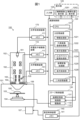
- FIG. 1 is a schematic diagram of a charged particle beam device according to a first embodiment of the present invention
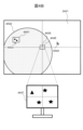
- FIG. 2 is a schematic diagram for explaining registration and display of a representative image in the first embodiment of the present invention.
- FIG. 2 is a schematic diagram for explaining registration and display of a representative image in the first embodiment of the present invention.
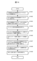
- 10 is a flowchart illustrating a navigation process using a representative image in a second embodiment of the present invention.
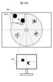
- FIG. 11 is a schematic diagram illustrating a navigation process using a representative image in a second embodiment of the present invention.
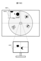
- FIG. 11 is a schematic diagram illustrating a navigation process using a representative image in a second embodiment of the present invention.
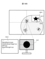
- FIG. 11 is a schematic diagram illustrating a navigation process using a representative image in a second embodiment of the present invention.
- FIG. 11 is a schematic diagram illustrating a navigation process using a representative image in a second embodiment of the present invention.
- FIG. 11 is a schematic diagram illustrating a navigation process using a representative image in a second embodiment of the present invention.
- FIG. 11 is a schematic diagram illustrating a navigation process using a representative image in a second embodiment of the present invention.
- FIG. 11 is a schematic diagram illustrating a navigation process using a representative image in a second embodiment of the present invention.
- 13 is a flowchart illustrating a navigation process within a display area range of a representative image in the third embodiment of the present invention.
- FIG. 11 is a schematic diagram illustrating a navigation process within a display area range of a representative image in a third embodiment of the present invention.
- FIG. 11 is a schematic diagram illustrating a navigation process within a display area range of a representative image in a third embodiment of the present invention.
- FIG. 11 is a schematic diagram illustrating a navigation process within a display area range of a representative image in a third embodiment of the present invention.
- FIG. 11 is a schematic diagram illustrating a navigation process within a display area range of a representative image in a third embodiment of the present invention.
- FIG. 11 is a schematic diagram illustrating a method of controlling navigation processing within a display area range of a representative image in a third embodiment of the present invention.
- FIG. 11 is a schematic diagram illustrating a method of controlling navigation processing within a display area range of a representative image in a third embodiment of the present invention.
- FIG. 11 is a schematic diagram illustrating a method of controlling navigation processing within a display area range of a representative image in a third embodiment of the present invention.
- FIG. 11 is a schematic diagram illustrating a method of controlling navigation processing within a display area range of a representative image in a third embodiment of the present invention.
- FIG. 13 is a schematic diagram illustrating a navigation process taking into account rotation of a stage in a fourth embodiment of the present invention.
- FIG. 13 is a schematic diagram illustrating a navigation process taking into account rotation of a stage in a fourth embodiment of the present invention.
- FIG. 13 is a schematic diagram illustrating a navigation process taking into account rotation of a stage in a fourth embodiment of the present invention.
- FIG. 13 is a schematic diagram for explaining a navigation process taking into consideration rotation of the stage (other than the origin) in Example 4 of the present invention.
- 13 is a schematic diagram for explaining a navigation process taking into consideration rotation of the stage (other than the origin) in Example 4 of the present invention.
- 13 is a flowchart illustrating a process of deleting the enlarged display size of a representative image in the fifth embodiment of the present invention.
- 13A and 13B are schematic diagrams illustrating a process of erasing the enlarged display size of a representative image in the fifth embodiment of the present invention.
- 13A and 13B are schematic diagrams illustrating a process of erasing the enlarged display size of a representative image in the fifth embodiment of the present invention.
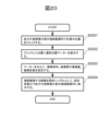
- 20 is a flowchart illustrating a navigation process by a mouse drag operation within a display area range of a representative image in a sixth embodiment of the present invention.
- FIG. 23 is a schematic diagram illustrating a navigation process by a mouse drag operation within a display area range of a representative image in the sixth embodiment of the present invention.
- FIG. 23 is a schematic diagram illustrating a navigation process by a mouse drag operation within a display area range of a representative image in the sixth embodiment of the present invention.
- 13 is a flowchart illustrating a navigation process by a digital zoom operation within a display area range of a representative image in a seventh embodiment of the present invention.
- 23 is a schematic diagram illustrating a navigation process by a digital zoom operation within the display area range of a representative image in the seventh embodiment of the present invention.
- FIG. 23 is a schematic diagram illustrating a navigation process by a digital zoom operation within the display area range of a representative image in the seventh embodiment of the present invention.
- FIG. 23 is a schematic diagram illustrating a navigation process by a digital zoom operation within the display area range of a representative image in the seventh embodiment of the present invention.
- FIG. 23 is a schematic diagram illustrating a navigation process by a digital zoom operation within the display area range of a representative image in the seventh embodiment of the present invention.
- FIG. 23 is a schematic diagram illustrating a navigation process by a digital zoom operation within the display area range of a representative image in the seventh embodiment of the present invention.
- FIG. 13 is a schematic diagram for explaining a change in the screen magnification of the observation position display unit in the eighth embodiment of the present invention.
- FIG. 13 is a schematic diagram for explaining a change in the screen magnification of the observation position display unit in the eighth embodiment of the present invention.
- FIG. 13 is a schematic diagram for explaining a change in the screen magnification of the observation position display unit in the eighth embodiment of the present invention.
- FIG. 13 is a flowchart illustrating a process of changing an observation condition of a charged particle beam device in a ninth embodiment of the present invention.
- FIG. 13 is a schematic diagram for explaining a process of changing an observation condition of a charged particle beam device in a ninth embodiment of the present invention.
- FIG. 13 is a schematic diagram for explaining a process of changing an observation condition of a charged particle beam device in a ninth embodiment of the present invention.
- FIG. 13 is a schematic diagram for explaining a process of changing an observation condition of a charged particle beam device in a ninth embodiment of the present invention.
- FIG. 13 is a schematic diagram illustrating a screen for setting a navigation operation in a ninth embodiment of the present invention.
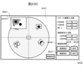
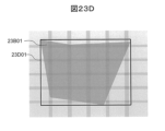
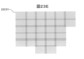
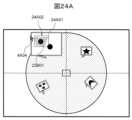
- FIG. 23 is a flowchart illustrating a procedure for setting continuous image capture based on coordinates designated in a display area range of a representative image in a tenth embodiment of the present invention.
- 13 is a schematic diagram for explaining a procedure for setting continuous image capture based on coordinates specified in the display area range of a representative image in a tenth embodiment of the present invention.
- FIG. 13 is a schematic diagram for explaining a procedure for setting continuous image capture based on coordinates specified in the display area range of a representative image in a tenth embodiment of the present invention.
- FIG. 23 is a flowchart illustrating a procedure for setting continuous image capture (range designation) using a representative image in an eleventh embodiment of the present invention.
- FIG. 13 is a schematic diagram for explaining a continuous image capturing setting procedure (range designation) using a representative image in the eleventh embodiment of the present invention.
- FIG. 13 is a schematic diagram for explaining a continuous image capturing setting procedure (range designation) using a representative image in the eleventh embodiment of the present invention.
- FIG. 13 is a schematic diagram for explaining a continuous image capturing setting procedure (range designation) using a representative image in the eleventh embodiment of the present invention.
- FIG. 13 is a schematic diagram for explaining a continuous image capturing setting procedure (range designation) using a representative image in the eleventh embodiment of the present invention.
- FIG. 13 is a schematic diagram for explaining a continuous image capturing setting procedure (range designation) using a representative image in the eleventh embodiment of the present invention.
- FIG. 13 is a schematic diagram for explaining a continuous image capturing setting procedure (range designation) using a representative image in the eleventh embodiment of the present invention.
- FIG. 13 is a schematic diagram for explaining a continuous image capturing setting procedure (range
- FIG. 23 is a schematic diagram for explaining a continuous image capture setting screen (coordinate designation) in the tenth embodiment of the present invention.
- FIG. 23 is a schematic diagram for explaining a continuous image capture setting screen (range designation) in the eleventh embodiment of the present invention.
- Charged particle beam devices use an electric field to accelerate charged particles such as electrons and positive ions (charged particles) and irradiate them onto a sample. Charged particle beam devices utilize the interaction between the sample and the charged particles to observe, analyze, process, and otherwise modify the sample.
- the embodiments described below are applicable to various charged particle beam devices (electron microscopes, electron beam lithography devices, ion processing devices, ion microscopes, observation and inspection devices that utilize these devices, etc.).
- the charged particle beam device 100 includes, as an example, a sample chamber 101, a charged particle beam optical system 102, a sample stage 103, a stage 104, a detector 105, a vacuum pump 107, a charged particle beam imaging device 110, an arithmetic and control unit 120, a stage control device 130, an optical imaging device 150, a vacuum control device 140, and an optical system control device 170.
- the sample chamber 101 has a function of maintaining a vacuum state inside to prevent scattering of the charged particle beam, and is configured so that a sample can be mounted inside.
- the vacuum control device 140 can control the vacuum pump 107 to perform the vacuum pumping operation of the sample chamber 101.
- the vacuum control device 140 can be equipped with a memory 141 for storing various parameters related to the vacuum pumping control.
- the charged particle beam optical system 102 includes a charged particle source 161 that generates an electron beam, a condenser lens 162 that narrows the electron beam emitted from the charged particle source 161, a deflector 163 that deflects the electron beam, an objective lens 164 that converges the electron beam, and the like.
- the optical system control device 170 has a memory 171 for storing various parameters related to the control of the charged particle beam optical system 102, and has the function of generating an electron beam from the charged particle source 161, constricting the electron beam with a condenser lens 162, deflecting and converging the electron beam with a deflector 163 and an objective lens 164, and controlling the irradiation of the sample 108 mounted on the sample stage 103.
- the configuration in FIG. 1 is an example, and the charged particle beam optical system 102 may include other lenses and electrodes in addition to the elements shown, and some of the elements may be replaced with other similar elements, and the details of the configuration are not limited to those shown.
- the sample stage 103 is mounted on the stage 104.
- the stage 104 can move the sample stage 103 in the XY directions (e.g., vertical and horizontal directions) within the sample chamber 101.
- the sample stage 103 can rotate around a rotation axis (e.g., parallel to the Z axis).
- the sample stage 103 holds the sample so that it can be tilted with the X or Y direction as the tilt axis.
- the stage 104 is controlled by the stage control device 130 in accordance with the calculation results in the calculation control unit 120, etc.
- the detector 105 has the function of detecting reflected electrons, secondary electrons, backscattered electrons (such as those due to EBSD: Electron Back Scattered Diffraction Pattern), inelastically scattered electrons (such as those related to EELS: Electron Energy Loss Spectroscopy), Auger electrons, cathodoluminescence (CL), X-rays (such as those related to EDS: Energy Dispersive X-ray Spectroscopy or WDS: Wavelength Dispersive X-ray Spectroscopy), etc., emitted from the sample 108.
- EBSD Electron Back Scattered Diffraction Pattern
- inelastically scattered electrons such as those related to EELS: Electron Energy Loss Spectroscopy
- Auger electrons Auger electrons
- X-rays such as those related to EDS: Energy Dispersive X-ray Spectroscopy or WDS: Wavelength Dispersive X-ray
- the number and position of the detectors 105 are not limited to any particular number.
- the charged particle beam imaging device 110 has a function of converting the signal detected by the detector 105 into an image, and has an internal memory 111 for storing the signal information.
- the optical imaging device 150 also has a function of capturing an optical image of the sample 108 in the sample chamber 101 with the optical camera 106, and converting the captured image signal into an optical image.
- the optical imaging device 150 has an internal memory 151 for storing the optical image.
- the arithmetic and control unit 120 is a control unit that controls various components of the charged particle beam device 100 and controls the display of the observation results according to the observation conditions input by the user.
- the arithmetic and control unit 120 is composed of an information processing device such as a computer.
- the arithmetic and control unit 120 has a CPU 121 (processor), a main storage device 122 such as a memory, and a secondary storage device 123 such as a hard disk drive (HDD) or a solid state drive (SSD) inside.
- a CPU 121 processor
- main storage device 122 such as a memory
- secondary storage device 123 such as a hard disk drive (HDD) or a solid state drive (SSD) inside.
- HDD hard disk drive
- SSD solid state drive
- the calculation and control unit 120 also includes an input unit 124 such as a keyboard, mouse, or touch monitor, a display unit 125 such as an LCD display (observation image display unit 1251 and observation position display unit 1252), and a communication unit (not shown) that communicates with each component of the charged particle beam device 100.
- an input unit 124 such as a keyboard, mouse, or touch monitor
- a display unit 125 such as an LCD display (observation image display unit 1251 and observation position display unit 1252)
- a communication unit not shown
- the calculation and control unit 120 and the display unit 125 constitute a sample observation support device according to this embodiment, and support the observation of an image of the sample captured by the charged particle beam device 100.
- the observation support device is configured as part of the charged particle beam device 100, but in a modified example, the observation support device may be configured independently of the charged particle beam device 100, in which case, for example, the observation support device may obtain an image output from the charged particle beam device 100 and support the observation of that image.
- the main memory device 122 stores a computer program that controls the overall operation of the charged particle beam device 100.
- the computer program is executed by the CPU 121 to provide functional blocks such as an information processing unit 1221, a representative image registration processing unit 1222, a display processing unit 1223, an input device monitoring processing unit 1224, a coordinate conversion processing unit 1225, and a condition control unit 1226.
- the information processing unit 1221 processes control information for the charged particle beam device 100.
- it is a processing unit that processes (including numerical calculations) together information such as acceleration voltage, emission current, magnification, beam spot, and working distance acquired from the optical system control device 170, information such as signal, image name, image resolution, field of view, imaging time, and time required for imaging acquired from the charged particle beam imaging device 110, information such as optical image name, optical image resolution, field of view, imaging time, and time required for imaging acquired from the optical imaging device 150, information such as stage coordinates acquired from the stage control device 130, and images such as vacuum degree acquired from the vacuum control device 140, and can also output the processed information as attribute information of the image.
- the representative image registration processing unit 1222 is a control unit for registering the acquired optical image of the sample 108 or an image converted from a signal (observation image) as a representative image displayed at an easily visible size, or canceling the registration as the representative image.
- the representative image registration processing unit 1222 registers a representative image based on multiple captured images.
- the display processing unit 1223 is a processing unit that performs display processing of the acquired optical image of the sample 108 or an image converted from a signal (observation image) based on information (attribute information at the time of imaging) such as stage coordinates, stage rotation angle, magnification (field of view), raster rotation, etc.
- raster rotation is defined as rotation in the scanning direction of the charged particle beam.
- the display processing unit 1223 controls the observation position display unit 1252. For example, even if the field of view of an image registered as a representative image is significantly different from the field of view of the observation position display unit 1252, processing is performed so that the representative image is always displayed at a size that is easy to view.
- the input device monitoring processing unit 1224 is a processing unit that constantly monitors input operations of an input device (mouse, touch monitor, etc.) via the cursor in the observation position display unit 1252, and determines, for example, whether the position specified by the mouse cursor is within the area range of the representative image.
- the coordinate conversion processing unit 1225 is a processing unit that processes mutual conversion between various types of coordinate systems, including the stage coordinate system of the charged particle beam device 100, the coordinate system of the acquired optical image of the sample 108 or the image converted from the signal (observation image), the coordinate system of the image registered as the representative image, and the coordinate system of the observation position display unit 1252.
- the condition control unit 1226 is a control unit that controls the reproduction process of the observation conditions and coordinate information of the representative image in the charged particle beam device 100 when the image registered as the representative image is used for sample navigation, and performs the process of switching the display field of view of the observation position display unit 1252 to an appropriate field of view. In this way, the condition control unit 1226 changes the observation conditions and stage coordinates of the charged particle beam device 100.
- the representative image refers to an image selected based on certain predetermined conditions from the group of images captured in the observation position display unit 1252.
- the display scale or display size is always controlled so that the representative image is of a size that is easy to view, so that the display position of the representative image is not lost.
- the meaning of "representative image” should not be interpreted as being limited to this.
- the stage control device 130 comprises a coordinate storage unit 131, a control unit 132, and a drive unit 133.
- the coordinate storage unit 131 stores the coordinates of the stage 104.
- the control unit 132 controls the operation of the entire stage control device 130.
- the drive unit 133 generates a drive signal to drive the stage 104.
- the control unit 132 acquires stage coordinate information from the coordinate storage unit 131 and transmits it to the calculation control unit 120. This allows the calculation control unit 120 to know the coordinate position of the captured image.
- the stage coordinates may be stored in the stage control device 130 or in the calculation control unit 120.
- FIG. 2A and 2B show examples of the observation position display screen of the charged particle beam device 100 according to the first embodiment.
- FIG. 2A is an example of the screen shown in the observation position display section 1252.
- the observation position display screen 2A01 is an image display section that displays the captured image based on information such as the imaging magnification, stage coordinates, and raster rotation (image attribute information at the time of image acquisition).
- This observation position display screen 2A01 can be configured, for example, as a virtual drawing canvas.
- the image attribute information in this embodiment is unique information associated with the image, such as the image name at the time of image acquisition, imaging time, time required for imaging, magnification, signal, image resolution, etc.
- the observation position display screen 2A01 is a position reference and displays an image of a sample captured by the charged particle beam device 100.
- the displayed image includes a background image and a captured image whose position is indicated in relation to the observation position display screen 2A01.
- the observation position display screen 2A01 is aligned (associated) with the stage coordinates of the charged particle beam device 100, and for each part of the sample, the position in the observation position display screen 2A01 corresponding to that part can be appropriately determined.
- the stage coordinates are expressed as (Xs, Ys) and the coordinates (pixel coordinates) of the observation position display screen 2A01 are expressed as (Xp, Yp)
- a function is specified for determining Xp and Yp based on Xs and Ys
- a function is specified for determining Xs and Ys based on Xp and Yp.
- a person skilled in the art can appropriately design a method for performing such alignment based on known techniques, etc., but as an example, a three-point alignment process or a dedicated sample holder may be used.
- the background image displayed on the observation position display screen 2A01 is, for example, an image of a wide area of a sample captured by the charged particle beam device 100, but is not limited to this.
- the background image is, for example, an image displayed according to the size of the observation position display screen 2A01. It is also possible not to display the background image (in which case the background displayed on the observation position display screen 2A01 may be blank, or another specified display may be displayed).
- the captured image is an image of a sample captured by the charged particle beam device 100, for example, display image 2A06.
- the observation position display screen 2A01 displays the positions of the multiple display images 2A06 as multiple captured images. For example, an image captured by the charged particle beam device 100 is displayed on the observation position display screen 2A01 aligned with the stage coordinates of the charged particle beam device 100. In this way, the observation position display screen 2A01 displays the positions of the multiple captured images of the sample captured by the charged particle beam device 100 in correspondence with the image display section of the observation position display screen 2A01.
- the screen magnification of the observation position display screen 2A01 is variable.
- the screen magnification of the observation position display screen 2A01 can be calculated from the ratio of the dimensions of the observation position display screen 2A01 to the screen field of view.
- the observation position display screen 2A01 can be aligned with the stage coordinates of the charged particle beam device 100 by affine transformation. For example, since the background image and captured images such as the display image 2A06 each have a magnification at the time of acquisition, when the magnification of the observation position display screen 2A01 is increased, a part of the background image and captured image is zoomed in and displayed (i.e. the number of pixels on one side of the image when displayed is variable).
- observation position display screen 2A01 and the background image and captured image displayed on the observation position display screen 2A01 each have a screen magnification and an image magnification, they can be displayed at a size ratio according to each magnification. For example, if the screen magnification of the observation position display screen 2A01 is 5000x, the magnification of the captured image is 20000x, and the number of pixels on the observation position display screen 2A01 is the same as the number of pixels at the time the captured image was captured, the captured image is displayed reduced so that the size of the captured image on the screen is 1/4 the size of the observation position display screen 2A01.
- the number of pixels on the observation position display screen 2A01 is 1280 x 960 pixels, and the screen magnification at initial display is 20,000 times.
- the size of the captured image matches the size of the observation position display screen 2A01 (i.e. the resolution (ratio of field of view and number of pixels) of the observation position display screen 2A01 and the captured image match), and the captured image is initially displayed as is at a size of 1280 x 960 pixels. If the magnification or number of pixels at the time of capture is different, the display size of the captured image on the screen is determined accordingly.
- the size of the captured image is also set to 640 x 480 pixels, half the original size (at the time of capture).
- the magnification of the observation position display screen 2A01 is set to 5,000 times, one-quarter of the original size
- the size of the captured image is also set to 320 x 240 pixels, one-quarter of the original size (at the time of capture).
- the size of the captured image must be enlarged according to the increased screen magnification. For example, if the screen magnification of the observation position display screen 2A01 is doubled from the initial magnification to 40,000, the size of the captured image will also be doubled from the initial size (at the time of capture) to 2560 x 1920 pixels.
- the method of determining the display content when the size of a captured image is changed can be appropriately designed by a person skilled in the art based on known techniques, etc. For example, when reducing the size, some of the pixels may be thinned out, and when enlarging the size, some of the pixels may be generated by interpolation.
- the screen magnification of the observation position display screen 2A01 is extremely low compared to the magnification of the captured image (e.g., display image 2A06).
- the magnification of the observation position display screen 2A01 is 5000 times and a captured image with a magnification higher than 5000 times is captured, the image is displayed as shown in Figure 2A.
- the observation position display screen 2A01 displays a magnification increase button 2A02, a magnification decrease button 2A03, a magnification reset button 2A04, and a magnification display section 2A05.
- registering an image as a representative image refers to the process of selecting a specific image from among candidates for representative images (for example, captured images) and determining that the selected image is the representative image. It may also include the process of storing information that the selected image is the representative image.
- the screen magnification of the observation position display screen 2A01 is reduced by using the magnification reduction button 2A03 or mouse wheel operation, or the screen magnification of the observation position display screen 2A01 is reset to the minimum magnification by operating the magnification reset button 2A04, and the screen magnification of the observation position display screen 2A01 becomes extremely low (for example, switched to 30x) compared with the image magnification of the display image 2A06 registered as the representative image.
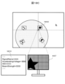
- the display image 2A06 registered as the representative image is always controlled to a size that is easy to view, and is displayed as the representative image 2B01 surrounded by a speech bubble frame.
- the display processing unit 1223 controls the representative image 2B01 to a size that is easy to view and displays it on the observation position display screen 2A01 of the observation position display unit 1252 in response to a change in the magnification of the image display unit of the observation position display screen 2A01.
- the representative image registration processing unit 1222 registers the specified captured image as the representative image 2B01.
- the specific registration process can be designed as appropriate, but for example, the image may be specified manually, or the representative image 2B01 may be automatically registered based on specific rules.
- the base of the speech bubble frame is displayed to point to the coordinates at which representative image 2B01 in the background image of the sample being displayed was observed or acquired.
- a background image of the sample is displayed, but it is not necessary to display a background image of the sample, or it is possible to display something other than a background image of the sample.
- representative image 2B01 is displayed using a speech bubble frame, a frame of a different shape may be used, or no frame may be used.
- the base of the speech bubble frame is used to indicate the image coordinates of the representative image 2B01, but a different shape such as an arrow may be used, or the image may be cut out and displayed without using an arrow.
- the size of an image refers to the size of the image when it is displayed on a screen (e.g., expressed in units of pixels), and does not necessarily correspond to the amount of data in the image (e.g., the number of pixels at the time of capture). In other words, the same image can be displayed in various sizes by enlarging or reducing it.
- controlling the representative image 2B01 to a size that is easy to view includes, for example, controlling the representative image 2B01 to a specific size.
- the "specific size” may be, for example, a fixed size regardless of the screen magnification of the observation position display screen 2A01.
- the size of the representative image 2B01 may be changed at a ratio that is not proportional to the change in the screen magnification of the observation position display screen 2A01.
- the specific process for realizing such size changes can be appropriately designed by a person skilled in the art based on known techniques, etc., but one example is shown below. For example, if the virtual size (field of view) corresponding to the observation position display screen 2A01 is 254 mm and the virtual size (field of view) of the representative image 2B01 is 127 mm, the representative image 2B01 will be displayed at half the size of the observation position display screen 2A01.
- the screen magnification of the observation position display screen 2A01 is reduced to half of the original.
- the field of view of the observation position display screen 2A01 becomes 508 mm, twice the original size.
- the field of view of the representative image 2B01 were to remain unchanged at 127 mm, the field of view of the representative image 2B01 would be 1/4 of the field of view of the observation position display screen 2A01, and therefore the size of the representative image 2B01 would also be 1/4 of the size of the observation position display screen 2A01, so the size of the representative image 2B01 would change and not become a fixed size.
- the field of view of the representative image 2B01 is changed according to the field of view of the observation position display screen 2A01. For example, if the field of view of the observation position display screen 2A01 becomes twice the original size, 508 mm, the field of view of the representative image 2B01 can be accordingly changed to twice the original size, 254 mm, so that the size of the representative image 2B01 can be fixed and displayed. Similarly, if the field of view of the observation position display screen 2A01 becomes four times the original size, 1016 mm, the field of view of the representative image 2B01 can be accordingly changed to four times the original size, 508 mm.
- the above specific processing can also be realized as control using a display layer.
- the virtual size of the screen display layer corresponding to the observation position display screen 2A01 is set as the field of view of the observation position display screen 2A01.
- the representative image display layer including the representative image 2B01 is displayed in an overlapping manner and has a virtual size different from that of the layer so as to correspond to the observation position display screen 2A01, and the field of view of the representative image 2B01 is determined based on the representative image display layer.
- the virtual size of the screen display layer changes in response to a change in the magnification of the observation position display screen 2A01, and the display position and display size of the sample background image and the captured image being displayed on the screen display layer also change.
- the magnification of the observation position display screen 2A01 decreases, it is also possible to gradually reduce the size of the representative image 2B01 at a pace slower than the rate at which the magnification decreases.
- the representative image 2B01 is controlled to a size that is easy to view, or is displayed at a size that is easy to view on the auxiliary display 2E01, thereby making it easy to identify the observation position without losing sight of the representative image 2B01.
- Example 2 of the present invention. Explanations of parts common to Example 1 may be omitted.
- step S301 the input device monitoring processing unit 1224 constantly monitors the position of the mouse cursor on the observation position display screen 2A01.
- step S302 when the user double-clicks the left mouse button at any position on the observation position display screen 2A01, the input device monitoring processing unit 1224 acquires the screen coordinates, and in step S303, it is determined whether the screen coordinates are within the display area of the representative image 4A01.
- the information processing unit 1221 acquires the stage coordinates (x, y) of the representative image 4A01 from the incidental information file that was created at the same time as the representative image 4A01 was captured, and that contains information such as the imaging conditions and stage coordinates.
- the coordinates (x, y) are described, but instead of or in addition to the X and Y coordinates, coordinates including the R coordinate, Z coordinate, T coordinate, etc. may be handled.
- step S305 the information processing unit 1221 generates a stage control signal based on the acquired stage coordinates and outputs it to the stage control device 130.
- the stage control device 130 drives the stage 104 to the movement position indicated by the stage control signal.
- step S306 the information processing unit 1221 acquires the imaging magnification of the representative image 4A01 from an auxiliary information file that was created at the same time as the representative image 4A01 was captured, and contains information such as imaging conditions and stage coordinates.
- the information processing unit 1221 generates an optical control signal based on the acquired imaging magnification, and outputs it to the optical system control device 170.
- the optical system control device 170 controls the scanning range of the electron beam so as to reproduce the magnification indicated in the optical control signal.
- condition control unit 1226 causes the charged particle beam device 100 to reproduce the magnification at the time the representative image 4A01 was captured. This allows the magnification to be reproduced automatically, improving work efficiency.
- the coordinate conversion processing unit 1225 acquires the screen coordinates in step S307, and converts them into stage coordinates by affine transformation processing in step S308.
- the translation transformation matrix of coordinates by affine transformation is shown below.
- T x and T y respectively indicate translation amounts (offset amounts), and applying a translation transformation matrix to screen coordinates makes it possible to convert to stage coordinates.
- rotation transformation, scaling, rotation, and/or skew transformation may also be used, and this embodiment is not limited to this embodiment.
- step S309 the coordinate conversion processing unit 1225 outputs the converted stage coordinates to the information processing unit 1221.
- a stage control signal is generated by the information processing unit 1221 and output to the stage control device 130.
- the stage control device 130 drives the stage 104 to the movement position indicated by the stage control signal.
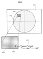
- FIGS 4A to 4D explain the sample navigation operations using the observation position display screen 2A01 and the representative image 4A01, respectively.
- FIG. 4A shows an example of an observation position display screen 2A01.
- This type of screen displays a central dotted cross line 4A05 that indicates the center of the observation position display screen 2A01, so that the position coordinate relationship can be easily understood to some extent from the sample background image, etc., even if the screen magnification becomes extremely high.
- the coordinate conversion processing unit 1225 calculates the field of view from the current magnification of the observation image being displayed on the observation image display unit 1251, and the display processing unit 1223 creates a rectangular dashed frame that represents a size that matches this field of view, and displays it on the observation position display screen 2A01 as the observation field of view dashed frame 4A06.
- the coordinate conversion processing unit 1225 converts the current stage coordinates into screen coordinates, and the observation field of view dashed line frame 4A06 is positioned based on this, but on the display, the observation field of view dashed line frame 4A06 is always at the center of the screen, and the position of the sample background image 4A02 is controlled to change during display.
- observation field of view dashed frame 4A06 is fixed at the center of the screen and the displayed sample background image 4A02 is moved according to the current stage coordinates, but the observation field of view dashed frame 4A06 may be moved while the displayed sample background image 4A02 is fixed, and this is not limited to this embodiment.
- the observation image corresponding to the observation field of view dashed frame 4A06 is displayed on the observation image display section 1251 (see Figure 1).
- the observation image display screen 4A07 is an example of such a screen, and polygonal and crescent-shaped structures are displayed.
- the double-clicked position is outside the display area of the representative image 4A01, so the screen coordinates of that position are converted to stage coordinates, and control is performed so that the stage 104 moves to those stage coordinates.
- the display processing unit 1223 moves the position of the double-clicked sample background image 4A02 being displayed so that it is at the center of the observation position display screen 2A01, as shown in FIG. 4B.
- the range of the sample being observed changes on the observation image display screen 4A07 in response to the movement of the stage 104, and so the observation image also changes.
- Fig. 4C when the left mouse button is double-clicked on the position of the mouse cursor 4A04 on the observation position display screen 2A01, the acquired screen coordinates are determined to be within the display area range of the representative image 4A01.
- the stage coordinates and imaging magnification are acquired from the incidental information file 4D01 (see Fig. 4D) that was created at the same time as capturing the representative image 4A01, and the stage 104 is moved and the imaging magnification is applied so that the observation field of the representative image 4A01 is reproduced on the observation image display screen 4A07 as shown in Fig. 4D.
- the input device monitoring processing unit 1224 acquires the position of the mouse cursor 4A04, and acquires the stage coordinates associated with the representative image 4A01 according to the position of the mouse cursor 4A04. Then, the condition control unit 1226 performs processing to move the stage 104 of the charged particle beam device 100 to the stage coordinates associated with the representative image 4A01.
- the condition control unit 1226 performs processing to move the stage 104 of the charged particle beam device 100 to the stage coordinates associated with the representative image 4A01. This allows the stage coordinates to be appropriately changed in response to a double click on the representative image 4A01.
- the display processing unit 1223 moves the position of the double-clicked sample background image 4A02 being displayed so that it is at the center of the observation position display screen 2A01, and the size of the observation field of view dashed line frame 4A06 is also changed according to the imaging magnification.
- the input device monitoring processing unit 1224 monitors the input position of the input device, determines whether the input position is within the display area range of the representative image 4A01, and then performs conversion processing to the corresponding stage coordinates, but this should not be interpreted as being limited to this embodiment.
- a correspondence table 4F01 is created in advance between information on the stage coordinates of the representative image 4A01 and the coordinate system of the target screen coordinate area 4E01 for all pixels (so-called target screen coordinate area 4E01) occupied by the display area range of the representative image 4A01 within the observation position display screen 2A01, it is possible to obtain the corresponding stage coordinates without determining whether the input position of the input device is within the display area range of the representative image 4A01.
- the position is specified by double-clicking the left mouse button, it may also be specified by a single click, or by an input device other than a mouse, such as touch input, and should not be interpreted as being limited to this embodiment.
- the charged particle beam device 100 of the second embodiment by determining whether the display area range of the representative image 4A01, which is always displayed at a size that is easily visible even if it is extremely far from the screen magnification of the observation position display screen 2A01, it is possible to easily reproduce the observation field of view of the representative image 4A01 without manipulating the screen magnification and screen position of the observation position display screen 2A01, leading to improved operability.
- Example 3 of the present invention. Explanations of parts common to Examples 1 and 2 may be omitted.
- step S501 the input device monitoring processing unit 1224 constantly monitors the position of the mouse cursor on the observation position display screen 2A01.
- step S502 after the user arbitrarily changes the position of the mouse cursor 4A04 on the observation position display screen 2A01, the input device monitoring processor 1224 acquires the screen coordinates of the position of the mouse cursor 4A04 and determines whether or not it is within the display area range of the representative image. If the screen coordinates are within the display area range of the representative image, the input device monitoring processor 1224 continues to monitor the position of the mouse cursor 4A04.
- step S503 the input device monitoring processing unit 1224 determines whether the position of the mouse cursor 4A04 remains within the display area range of the representative image for a certain period of time or more. If it is determined that the mouse cursor 4A04 has remained within the display area range of the representative image for longer than the preset period of time, in step S504, the display processing unit 1223 enlarges and displays the representative image at a predetermined scale.
- the display processing unit 1223 enlarges and displays the representative image at a predetermined scale.
- Enlarging at a predetermined scale includes, but is not limited to, enlarging to a predetermined display size that is larger than the original display size.
- step S505 when the user double-clicks the mouse at any position within the display area of the enlarged representative image, in step S506, the input device monitoring processing unit 1224 acquires the screen coordinates of that position.
- step S507 the information processing unit 1221 acquires the stage coordinates (x, y) and imaging magnification of the representative image from the incidental information file that was created at the same time as the representative image was captured and contains information such as imaging conditions and stage coordinates.
- the coordinates (x, y) are described, but instead of or in addition to the X and Y coordinates, coordinates including the R coordinate, Z coordinate, T coordinate, etc. may be handled.
- step S508 the screen coordinates acquired by the coordinate conversion processing unit 1225 are subjected to translation affine transformation processing, thereby converting them into stage coordinates. Details of this coordinate conversion processing will be described later (see FIG. 7). Also, in this embodiment, only translation transformation is used, but depending on the use case, rotation transformation, scaling, rotation, skew transformation, etc. may also be used, and this embodiment is not limited to this.
- step S509 the coordinate conversion processing unit 1225 outputs the converted stage coordinates to the information processing unit 1221, which generates a stage control signal and outputs it to the stage control device 130.
- the stage control device 130 drives the stage 104 to the movement position indicated by the stage control signal.
- step S510 the information processing unit 1221 generates an optical control signal based on the imaging magnification obtained from the supplementary information file of the representative image, and outputs it to the optical system control device 170.
- the optical system control device 170 controls the scanning range of the electron beam so as to reproduce the magnification indicated in the optical control signal.
- step S502 the input device monitoring processing unit 1224 acquires the screen coordinates of the position of the mouse cursor 4A04, and if it determines that the screen coordinates are outside the display area range of the representative image, it skips steps S503 to S510.
- step S503 determines in step S503 that the mouse cursor 4A04 is not within the display area of the representative image for a certain period of time or longer. steps S504 to S510 are omitted.
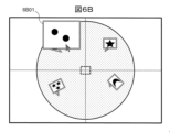
- Figures 6A to 6D are schematic diagrams illustrating navigation processing within the display area range of a representative image.
- the display processing unit 1223 enlarges the representative image 4A01 at a predetermined scale and displays it as an enlarged representative image 6B01, as shown in Fig. 6B. Details of the representative image enlargement process will be described later (see Fig. 7A).
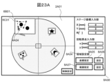
- two circular structures are displayed in the enlarged representative image 6B01, and as an example, when the mouse cursor 4A04 is moved to the center of the upper left circular structure and the center is double-clicked with the left mouse button, a selection position marker 6C01 is displayed at the clicked position (the center of the circular structure in this example).
- a cross-shaped selection position marker is used, but a circle, square triangle, or other shape may also be used, and this is not limited to this example.
- the input device monitoring processing unit 1224 acquires the screen coordinates of the selection position marker 6C01, and the information processing unit 1221 acquires the stage coordinates (x, y) and imaging magnification of the representative image from an additional information file that was created at the same time as the representative image was captured and contains information such as the imaging conditions and stage coordinates.
- the screen coordinates of the selection position marker 6C01 are converted to the corresponding stage coordinates by the coordinate conversion processing unit 1225.
- the detailed processing of the coordinate conversion will be described later (see FIG. 7B).
- the stage 104 is moved to the stage coordinates determined by the conversion processing, and the magnification is changed to an appropriate magnification.
- the observation image display unit 1251 the observation image of the sample corresponding to the screen coordinates of the selection position marker 6C01 is reproduced at an appropriate magnification with the circular structure at the center.
- the method of calculating the "appropriate magnification” here can be determined appropriately by a person skilled in the art, but it can be, for example, a magnification equal to the imaging magnification of the representative image, a magnification close to the imaging magnification of the representative image, a magnification calculated as a result of image processing on the enlarged representative image 6B01 (for example, a magnification corresponding to the size of the smallest rectangle that encloses the entire area of the circular structure obtained by the binarization processing and structure extraction processing on the enlarged representative image 6B01), etc.
- the display processing unit 1223 moves the sample background image 4A02 being displayed so that the screen coordinates of the selected position marker 6C01 are located at the center of the observation position display screen 2A01, and the size of the observation field of view dashed line frame 4A06 is also changed according to the applied magnification.
- Figures 7A to 7C are schematic diagrams that explain how navigation processing is controlled within the display area range of the representative image.
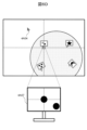
- FIG. 7A is a schematic diagram for explaining a process of affine transformation of an observation image captured by the charged particle beam device 100 to a stage coordinate region.
- the coordinate systems of the observation image coordinate region 7A01 and the stage coordinate region 7A02 are both positive in the right direction of the X axis and the downward direction of the Y axis, and the upper left vertex is the origin.
- the width and height of the observation image coordinate region are ImgWidth and ImgHeight, respectively, as shown by the image coordinate/stage coordinate transformation dotted line 7A03, it is possible to link the center position (ImgWidth/2, ImgHeight/2) of the observation image coordinate region to the actual stage coordinates (X, Y) by the following affine transformation process.
- the observation image coordinate area 7A01 and the stage coordinate area 7A02 are linked at a 1:1 ratio, so when the observation image coordinate area 7A01 is displayed on the observation position display screen 2A01, if the viewing range of the observation image coordinate area 7A01 and the viewing range of the observation position display screen 2A01 are too far apart, the observation image area becomes too small and cannot be seen.
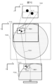
- a scale control matrix is applied so that the representative image can always be displayed at an easily recognizable size regardless of the screen magnification of the observation position display screen 2A01. Then, as shown in Fig. 7B, by changing the display size of the representative image with the scale control matrix (magnification ratio: Scale) along with the change in the field of view of the observation position display screen 2A01, it becomes possible to always display the representative image at an easily recognizable size.
- the above formula makes it possible to convert the observation image coordinate area 7A01 into the representative image display area 7B01 and into the stage coordinate area 7A02.
- FIG. 7C is a schematic diagram explaining the affine transformation process from the representative image display area 7B01 to the observation position display screen coordinate area 7C02.
- the observation position display screen coordinate area 7C02 like the observation image coordinate area 7A01 and the stage coordinate area 7A02, has the rightward direction of the X axis and the downward direction of the Y axis as positive in the coordinate system, and the upper left vertex as the origin.
- the enlarged representative image 6B01 is displayed at coordinates (a, b) on the observation position display screen coordinate area 7C02, so that it is possible to link them by the following affine transformation processing.
- the base of the balloon frame surrounding the enlarged representative image 6B01 indicates the actual imaging position (c, d) of the enlarged representative image 6B01, and can be obtained as follows along the stage coordinate/screen coordinate conversion dotted line 7C01.
- the corresponding stage coordinates can be obtained by applying the inverse transformation matrix of equation (4) to the double-clicked screen coordinates (ClickX, ClickY).
- transformation processing may be performed for the R coordinate, Z coordinate, T coordinate, coordinate in the rotation direction of the observation position display screen 2A01, etc., and is not limited to this embodiment.
- it may also include transformation processing for shifting the x and y coordinates of the charged particle beam by the optical system control device, and rotation in the scanning direction (raster rotation), etc.
- Example 4 of the present invention. Explanations of parts common to Examples 1 to 3 may be omitted.
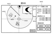
- FIGS. 8A to 8C are schematic diagrams illustrating navigation processing that takes into account the rotation of the stage 104.
- FIG. 8A shows the operation control section 8A01 and the rotation bar 8A10 of the observation position display screen 2A01.
- the stage coordinate input unit 8A02 allows manipulation of the X, Y and R coordinates of the stage 104.
- the rotation origin input unit 8A03 allows the rotation origin of the stage 104 to be set.
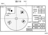
- the area setting unit 8A04 is a setting unit that sets the imaging area for the range of the sample, and allows point and area specification (described later in Figures 21A to 26).
- the control setting button 8A09 calls up a control setting screen 1900 (see FIG. 19) for performing various settings when operating the charged particle beam device 100.
- the rotation bar 8A10 is a marker for displaying the rotation angle of the sample background image 4A02 being displayed, and the display angle changes according to the rotation angle of the stage 104.
- each observation image is displayed according to its respective rotation angle, as shown in Fig. 8A.
- a rotation transformation matrix is applied to Equation (3) and Equation (4) as follows:
- ⁇ represents the R coordinate of the stage 104.
- the coordinate conversion processing unit 1225 performs the mutual conversion of the coordinate systems based on the stage rotation angle and center of rotation of the charged particle beam device 100.
- the representative image 8A11 is enlarged as shown in Fig. 8C.
- the selection position marker 6C01 is displayed at the designated position, and the screen coordinates of that position are acquired. In this case, it becomes possible to convert the acquired screen coordinates into stage coordinates by using equation (9) obtained by substituting equation (8) into equation (6), and it becomes possible to accurately move the position of the stage 104.
- Figures 9A and 9B are schematic diagrams illustrating navigation processing that takes into account the rotation of the stage 104 when it is not at the rotation origin. As shown in Figure 9A, if the rotation origin center 9A01 of the stage 104 is not at the center of the stage coordinate area 7A02, for example at a position (20, 10), creating a transformation matrix that takes the rotation origin into account for equations (3) and (4) makes it possible to display representative images captured at different rotation angles.
- the observation position display screen 2A01 rotates around the rotation origin center 9A01 as shown in FIG. 9B.
- equation (6) that takes the rotation origin into account, it becomes possible to convert the screen coordinates of any position within the display area range of the enlarged representative image 8C01 into stage coordinates, and it becomes possible to move the position of the stage 104 accurately.
- Example 5 of the present invention. Explanations of parts common to Examples 1 to 4 may be omitted.
- step S1001 when the mouse cursor 4A04 is moved within the display area range of the enlarged representative image 6B01 enlarged at a predetermined scale on the observation position display screen 2A01, in step S1002, the input device monitoring processing unit 1224 acquires the screen coordinates of the position of the mouse cursor 4A04 and determines whether it is within the display area range of the enlarged representative image 6B01.
- step 1004 the enlarged display of the enlarged representative image 6B01 is maintained.
- step S1002 If it is determined in step S1002 that the mouse cursor 4A04 has been moved outside the display area of the enlarged representative image, then in step 1003, the display processing unit 1223 erases the enlarged display of the enlarged representative image 6B01, i.e., returns the display size of the enlarged representative image 6B01 to the display size of the original representative image.
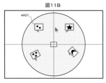
- Figures 11A and 11B are schematic diagrams that explain the process of erasing the enlarged display of a representative image by hovering the mouse over it.
- the display processing unit 1223 erases the enlarged display of the enlarged representative image 6B01 and returns the display size to the original so that it becomes the representative image 4A01, as shown in FIG. 11B.
- the display processing unit 1223 redisplays the enlarged representative image 6B01, which was enlarged and displayed at a specified scale, at the original scale.
- Example 6 of the present invention. Explanations of parts common to Examples 1 to 5 may be omitted.
- Steps S1201 to S1204 may be the same as in Example 3 (see Figure 5), so duplicated explanations will be omitted.
- step S1205 the user sets any position within the display area of the enlarged representative image 6B01 as the start point and drags the mouse from that position.
- step 1206 the position where the mouse drag operation ends is set as the end point, and the input device monitoring processing unit 1224 obtains the screen coordinates of the start and end points of the mouse drag and passes them to the display processing unit 1223.
- the display processing unit 1223 uses the screen coordinates of the start and end points to draw a rectangular marker within the display area of the enlarged representative image 6B01.
- step S1207 the display processing unit 1223 obtains the screen coordinates of the center position of the rectangular marker, and in step S1208, the coordinate transformation processing unit 1225 transforms them into the corresponding stage coordinates through affine transformation processing, and transmits them to the information processing unit 1221.
- step S1209 the information processing unit 1221 generates a stage control signal based on the acquired stage coordinates and outputs it to the stage control device 130.
- the stage control device 130 drives the stage 104 to the movement position indicated by the stage control signal.
- step S1210 the display processing unit 1223 obtains the screen coordinates of the top left and top right vertices of the rectangular marker, which are then transformed by the coordinate transformation processing unit 1225 into the corresponding stage coordinates through affine transformation processing, and transmitted to the information processing unit 1221.
- step S1211 the information processing unit 1221 determines the difference between the stage coordinates of the upper left vertex and the upper right vertex, and then determines the magnification by calculating the ratio of a predetermined reference dimension to the difference.
- step S1212 the information processing unit 1221 generates an optical control signal based on the determined magnification, and outputs it to the optical system control device 170.
- the optical system control device 170 controls the scanning range of the electron beam so as to reproduce the magnification indicated in the optical control signal.
- the coordinate conversion processing unit 1225 converts the screen coordinates of the upper left and upper right vertex positions and the center position of the enlarged representative image 6B01 into the stage coordinate system, and calculates the magnification from the ratio of a predetermined reference dimension to the difference between the stage coordinates of the upper left and upper right vertex positions.
- the coordinate conversion processing unit 1225 then causes the observation support device to reproduce the stage coordinates and magnification of the center position.
- FIGS. 13A and 13B are schematic diagrams illustrating navigation processing by mouse dragging within the display area of the enlarged representative image 6B01.
- the screen coordinates of the center position of rectangular marker 13A03 are transformed into stage coordinates by affine transformation processing, and stage 104 is controlled to move to those stage coordinates.
- the screen coordinates of the upper left vertex position and the upper right vertex position of the rectangular marker are transformed into the corresponding stage coordinates by affine transformation, and then the difference between the stage coordinates is calculated.
- the magnification is calculated and applied to the screen magnification of the observation image display screen 4A07. In this way, the field of view is reproduced on the observation image display screen 4A07 at a position and magnification corresponding to the rectangular marker 13A03.
- the input device monitoring processing unit 1224 acquires the start and end positions of the input operation within the display area range of the enlarged representative image 6B01, and the display processing unit 1223 displays rectangular markers corresponding to the start and end positions in the display area of the enlarged representative image 6B01.
- Example 7 of the present invention. Explanations of parts common to Examples 1 to 6 may be omitted.
- the input device (such as a mouse) has a rotating member (in the following example, a mouse wheel).
- step S1401 the user rotates the mouse wheel within the display area of the enlarged representative image 6B01.
- the input device monitoring processing unit 1224 acquires the direction and amount of rotation of the mouse wheel, and outputs this to the coordinate conversion processing unit 1225.
- the coordinate conversion processing unit 1225 creates an appropriate scale conversion matrix according to the direction and amount of rotation of the mouse wheel.
- the input device monitoring processing unit 1224 acquires the direction and amount of rotation of the mouse wheel when the position of the mouse cursor 4A04 is within the display area range of the enlarged representative image 6B01. Then, the coordinate transformation processing unit 1225 creates a scale transformation matrix according to the direction and amount of rotation of the mouse wheel.
- step S1402 the display processing unit 1223 applies this scale transformation matrix and digitally zooms in/out around the mouse cursor 4A04 in the display area range of the enlarged representative image 6B01, enlarging/reducing the display area range. In this way, the display processing unit 1223 digitally zooms in/out the enlarged representative image 6B01 by applying the scale transformation matrix around the position of the mouse cursor 4A04.
- step S1403 when the user double-clicks the mouse cursor 4A04 at any position within the digitally zoomed display area range of the enlarged representative image 6B01, in step S1404, the input device monitoring processing unit 1224 acquires the screen coordinates of that position and outputs them to the coordinate conversion processing unit 1225.
- step S1405 the coordinate conversion processing unit 1225 converts the screen coordinates into corresponding stage coordinates and transmits them to the information processing unit 1221.
- step S1406 the information processing unit 1221 generates a stage control signal based on the acquired stage coordinates and outputs it to the stage control device 130.
- the stage control device 130 drives the stage 104 to the movement position indicated by the stage control signal.
- step S1407 the display processing unit 1223 obtains the screen coordinates of the upper left vertex and upper right vertex of the digitally zoomed display area range of the enlarged representative image 6B01, and outputs them to the coordinate transformation processing unit 1225. These are then transformed into the corresponding stage coordinates by affine transformation, and sent to the information processing unit 1221.
- step S1408 the information processing unit 1221 determines the difference between the stage coordinates of the upper left vertex and the upper right vertex, and then determines the magnification by calculating the ratio of a predetermined reference dimension to the difference.
- step S1409 the information processing unit 1221 generates an optical control signal based on the determined magnification, and outputs it to the optical system control device 170.
- the optical system control device 170 controls the scanning range of the electron beam so as to reproduce the magnification indicated in the optical control signal.
- the input device monitoring processing unit 1224 acquires the position of the mouse cursor 4A04 within the display area range of the digitally zoomed enlarged representative image 6B01.
- the coordinate conversion processing unit 1225 converts the position of the mouse cursor 4A04 into the stage coordinate system, converts the screen coordinates of the upper left vertex and upper right vertex in the display area range of the digitally zoomed enlarged representative image 6B01 into the corresponding stage coordinate system, and calculates the difference between the stage coordinates of the upper left vertex and upper right vertex, and then calculates the magnification from the ratio of a predetermined reference dimension to the difference.
- the condition control unit 1226 moves the stage 104 of the charged particle beam device 100 to the position of the mouse cursor 4A04 converted into the stage coordinate system, and reproduces the calculated magnification.
- FIGS. 15A to 15D are schematic diagrams illustrating navigation processing using digital zoom operations within the display area range of the enlarged representative image 6B01.
- digital zoom is performed around the mouse cursor by rotating the mouse wheel, etc., within the display area range of the enlarged representative image 6B01. Also, to show the digital zoom scale of the enlarged representative image 6B01, a digital zoom scale bar 15A01 is displayed to the left of it, and the digital zoom ratio ranges from the original display scale (min) to a predetermined maximum digital zoom in scale (max).
- the mouse wheel is rotated between two circular structures, and the display area range of the enlarged representative image 6B01 is digitally zoomed in accordance with the amount of rotation.
- the slider of the digital zoom scale bar 15A01 is also moved to the corresponding digital zoom ratio.
- the display processing unit 1223 displays a digital zoom scale bar to the left of the digitally zoomed enlarged representative image 6B01, and changes the position of the slider of the digital zoom scale bar according to the digital zoom ratio. This allows the user to easily change the digital zoom ratio.
- the user moves the mouse cursor 4A04 upward within the display area of the digitally zoomed enlarged representative image 6B01 and double-clicks.
- the screen coordinates of the clicked position are converted into stage coordinates, and the stage 104 is moved to that position.
- the screen coordinates of the top left and top right vertices in the digitally zoomed display area range of the enlarged representative image 6B01 are converted to the corresponding stage coordinates, and the magnification is calculated by calculating the ratio of a predetermined reference dimension to the difference between the stage coordinates, and is applied to the screen magnification of the observation image display screen 4A07.
- a rectangular marker 13B01 corresponding to the digitally zoomed range is drawn in the display area range of the representative image.
- Example 8 of the present invention. Explanations of parts common to Examples 1 to 7 may be omitted.
- Figures 16A and 16B are schematic diagrams explaining the process of changing the screen coverage ratio of the observation position display section 1252 (see Figure 1).
- the user double-clicks on the center of the upper left circular structure of two circular structures displayed in the display area range of the enlarged representative image 6B01.
- the screen coordinates of the center are converted to stage coordinates by affine transformation processing in the same way as described in the above-mentioned Examples 2 to 7, and the stage 104 is controlled to move to those stage coordinates.
- the imaging magnification is obtained from the supplementary information file of the enlarged representative image 6B01 and applied to the screen magnification of the observation image display screen 4A07.
- the display position of the observation position display screen 2A01 is moved to match the double-clicked screen coordinates, and the screen scale conversion is performed so that the screen magnification also matches the imaging magnification of the enlarged representative image 6B01.
- the center of the circular structure in the upper left becomes the center of the observation position display screen 2A01, and the screen magnification is switched to the imaging magnification of the representative image, for example 5000x.
- the display processing unit 1223 switches the range of the enlarged representative image 6B01 that corresponds to the display area range to a range centered on the position of the mouse cursor 4A04, and applies the magnification at the time of capturing the enlarged representative image 6B01 as the magnification of the observation position display unit 1252.
- the screen magnification of the observation position display screen 2A01 is switched to the imaging magnification of the enlarged representative image 6B01, but it may be switched to any other appropriate screen magnification, and should not be interpreted as being limited to this embodiment.
- Example 9 of the present invention. Explanations of parts common to Examples 1 to 8 may be omitted.
- step S1701 for example, it is assumed that the current position of the stage 104 is within the display area range of representative image A, and the field of view is being observed under observation condition A.
- step S1702 the user manually operates the stage 104, or uses the navigation processing of Examples 2 to 8 to move the stage 104 from the display area range of representative image A to within the display area range of representative image B.
- step S1703 since the information processing unit constantly manages the current coordinates of the stage 104, when it detects that the stage 104 is within the display area range of representative image B, it obtains observation condition B from the supplementary information file of representative image B, and in step S1704 applies the observation condition to the charged particle beam device 100, switching from observation condition A to observation condition B.
- condition control unit 1226 causes the charged particle beam device 100 to reproduce the observation conditions for representative image B.
- the "observation conditions" described in this embodiment include at least one of the following: the accelerating voltage of the charged particle beam, the beam intensity (the intensity of the current flowing through the capacitor), the beam scanning range (magnification), the beam working distance (WD), the image quality (contrast, brightness), and the type of signal detected from the sample (reflected electrons, secondary electrons, backscattered electrons, inelastically scattered electrons, Auger electrons, cathodoluminescence, X-rays).
- Figures 18A to 18C are schematic diagrams explaining the process of changing the observation conditions of the charged particle beam device 100.
- the current position of the stage 104 is within the display area range of the representative image A18A01, observation condition A18A03 is applied to the charged particle beam device 100, and the field of view shown on the observation image display screen 4A07 is displayed.
- the representative image B18A02 is enlarged and displayed at a specified scale, as shown in FIG. 18B. If the apex of the upper right protrusion of the star-shaped structure displayed in the enlarged representative image 18B01 is double-clicked, the stage 104 moves to the clicked position by the navigation processing of Example 3.
- the observation condition of the charged particle beam device 100 switches from observation condition A18A03 to observation condition B18C01 as shown in FIG. 18C, and the appearance of the field of view changes as shown on the observation image display screen 4A07.
- observation condition setting section 1901 of the control setting screen 1900 which is called up from the control setting button 8A09, it is possible to switch the reproduction of the detection signal type, acceleration voltage, intensity, working distance, and magnification.
- the coordinate condition setting section 1902 it may be possible to switch the reproduction conditions of the coordinates.
- this embodiment describes switching from the observation conditions of the observation position display screen 2A01 to the observation conditions of the representative image including the current position of the stage 104, but it is possible to switch to conditions other than the observation conditions defined in this embodiment, and this should not be interpreted as being limited to this embodiment.
- Example 10 of the present invention. Explanations of parts common to Examples 1 to 9 may be omitted.
- step S2001 when the user clicks on any position within the display area of the enlarged representative image, the input device monitoring processing unit 1224 acquires the screen coordinates of the clicked position and outputs them to the display processing unit 1223.
- step S2002 the display processing unit 1223 displays a selection position marker 6C01 at the corresponding position within the display area of the enlarged representative image 6B01 based on the received screen coordinates.
- step S2003 the magnification of the continuously captured images, the amount of overlap between the images, and the number of images captured in each of the X and Y directions are set with the screen coordinates of the selection position marker 6C01 as the center.
- the information processing unit 1221 outputs this setting information to the display processing unit 1223.
- the display processing unit 1223 represents each of the continuously captured images as a rectangular symbol, and displays them within the display area range of the enlarged representative image 6B01, arranged in the number of images captured with some overlap in the X and Y directions.
- Figures 21A and 21B are schematic diagrams explaining the procedure for setting up continuous imaging based on the coordinates specified in the display area range of the representative image.
- the observation position display screen 2A01 switches to a mode in which a continuous imaging area can be set by specifying coordinates.
- a selection position marker 6C01 is displayed at that position.
- a coordinate designation setting screen 2500 as shown in FIG. 25 is called up.
- the coordinate designation setting screen 2500 it is possible to set the magnification of the group of images to be captured continuously in the magnification setting section 2501, the amount of overlap between images in the overlap setting section 2502, and the number of images to be captured in each of the X and Y directions in the number setting section 2503, with the selection position marker 6C01 at the center.
- the display processing unit 1223 converts images captured continuously around the selection position marker 6C01 into rectangular symbols, and displays the set number of images in the X and Y directions in the display area of the enlarged representative image 6B01 in real time.
- the display processing unit 1223 displays the specified position specified via the mouse cursor 4A04 with a position marker within the display area range of the enlarged representative image 6B01.
- the information processing unit 1221 generates setting information for continuous imaging according to the specified position.
- the setting information includes the magnification, the amount of overlap between images, the number of images captured in the X direction, and the number of images captured in the Y direction.
- the display processing unit 1223 displays the group of images related to the continuous imaging as a group of rectangular symbols based on the setting information.
- the display processing unit 1223 displays the designated center position specified via the mouse cursor 4A04 with a position marker within the display area range of the enlarged representative image 6B01.
- the information processing unit 1221 generates setting information centered on this designated center position.
- rectangular semi-transparent symbols are used to represent images captured continuously, but non-rectangular symbols or opaque symbols may also be used, and should not be interpreted as being limited to this embodiment.
- the group of consecutively captured images 21B01 is set with the designated coordinates as the center, but the designated coordinates may also be the center coordinates of the top leftmost image in the group of consecutively captured images 21B01, and should not be interpreted as being limited to this embodiment.
- Example 11 of the present invention The following describes Example 11 of the present invention. Explanations of parts common to Examples 1 to 10 may be omitted.
- step S2201 when the user clicks multiple arbitrary positions within the display area of the enlarged representative image 6B01, the input device monitoring processing unit 1224 acquires the screen coordinates of each clicked position and outputs them to the display processing unit 1223.
- the display processing unit 1223 displays the selection position marker 6C01 at each position based on the received screen coordinates.
- step S2202 when the click operation is completed, the display processing unit 1223 sequentially connects each of the multiple selection position markers 6C01, and ultimately creates a polygon with each position as a vertex, which is displayed within the display area range of the enlarged representative image 6B01. In this way, the user can create a polygon of any shape.
- step S2203 the display processing unit 1223 creates the smallest rectangle that contains the entire polygon (the rectangle with the smallest diagonal length). It also calculates the screen coordinates of the four vertices of the rectangle and outputs them to the information processing unit 1221.
- step S2204 the user sets the imaging magnification and the amount of overlap between images.
- the information processing unit 1221 calculates the number of images to be captured so that the rectangular area surrounding the polygon is filled, and displays the continuously captured images as rectangular symbols. Once the imaging magnification and the amount of overlap between images are set, the field of view of a single image can be calculated.
- any two vertices of a rectangle enclosing a polygon for example the top left and top right vertices, but it could also be the top left and bottom right vertices, bottom left and bottom right vertices, top left and bottom left vertices, etc.
- the size of the rectangle enclosing the polygon can be found. In this way, it is possible to calculate the number of images to be taken so that the rectangular area enclosing the polygon is filled.
- step S2205 the group of consecutively captured images is checked for overlap with the polygon, one by one, from the top left to the bottom right. Note that in order to increase the accuracy of the overlap determination between the group of consecutively captured images and the polygon, the overlap determination is not performed in the screen coordinate system, but rather the area of the polygon of any shape is converted to the stage coordinate system before the determination is performed.
- step S2206 the information processing unit 1221 executes a process for determining whether or not there is an overlapping area between the polygon and the captured image. If it is determined that there is an overlapping area between the two, in step S2207, the information processing unit 1221 sets that image as a target image for continuous capture, and repeats the overlap determination with the next image.
- step S2206 If it is determined in step S2206 that there is no overlapping area between the two images, the information processing unit 1221 sets the image as not being a target image for continuous image capture, and repeats the overlap determination with the next image.
- Figures 23A to 23E are schematic diagrams explaining the procedure for setting up continuous image capture within the range specified by the display area range of the representative image.
- the observation position display screen 2A01 switches to a mode in which a continuous imaging area can be set by specifying a range. In this mode, if multiple arbitrary positions are specified in order around the upper left circular structure of the two circular structures in the display area range of the enlarged representative image 6B01, a selection position marker 6C01 is displayed at each position.
- the display processing unit 1223 sequentially connects the multiple selection position markers 6C01, and ultimately creates a polygon 23B01, which is displayed within the display area range of the enlarged representative image 6B01.
- the display processing unit 1223 displays the polygon by connecting each specified position with a line. This allows the user to easily specify the shape of the polygon.
- a range designation setting screen 2600 is called up as shown in FIG. 26.
- the magnification of the group of images to be captured continuously is set in the magnification setting section 2501
- the overlap amount between the images is set in the overlap amount setting section 2502, allowing the field of view of a single image to be calculated.
- the screen coordinates of the vertices of a rectangle 23D01 enclosing a polygon 23B01 are transformed into stage coordinates using an affine transformation, and the difference between the stage coordinates of the two vertices is found, thereby determining the size of the rectangle enclosing the polygon.
- the display processing unit 1223 displays two or more designated positions specified via the mouse cursor 4A04 with position markers within the display area range of the enlarged representative image 6B01.
- the information processing unit 1221 generates setting information for continuous imaging in accordance with each designated position.
- the display processing unit 1223 displays a group of images related to continuous imaging as a group of rectangular symbols based on the setting information.
- the information processing unit 1221 also calculates the field of view of one image based on the magnification and the amount of overlap between images included in the setting information. Next, the information processing unit 1221 calculates the size of a rectangle surrounding a polygon from the difference between the stage coordinates of two vertices of the rectangle surrounding the polygon. Next, the information processing unit 1221 calculates the number of images so that the rectangular area is filled based on the field of view of one image and the size of the rectangle. Next, the information processing unit 1221 selects one or more images from the group of images related to the continuous imaging as images to be captured based on the overlap determination result between the group of images related to the continuous imaging and the polygon. This type of processing makes it possible to efficiently capture only the necessary area.
- the target image is displayed as a rectangular symbol within the display area range of the enlarged representative image 6B01, as shown in FIG. 23C.
- the overlap determination between the area of the arbitrarily shaped polygon and the rectangular symbol representing the image is performed in the stage coordinate system, but the determination may also be performed in the screen coordinate system on the observation position display screen 2A01, and should not be interpreted as being limited to this embodiment.
- this embodiment describes the setting of a continuous imaging area in X and Y coordinates, but the rotation angle of the set area may be changed, and should not be interpreted as being limited to this embodiment.
- area range rectangular frame 24A01 is displayed as a rectangle surrounding the polygon.
- Area range rectangular frame 24A01 has a rotation operation portion 24A02. If the user performs a rotation operation (e.g., clockwise) while holding rotation operation portion 24A02 of area range rectangular frame 24A01, polygon 23B01 rotates clockwise, as shown in FIG. 24B. In other words, when an operation is performed on rotation operation portion 24A02 via mouse cursor 4A04, the polygon rotates in response to that operation. This type of processing allows the user to specify the area to be captured more freely.
- a rotation operation e.g., clockwise
- the image rectangle symbol representing the group of consecutively captured images 22A03 is set in a rotated state.
- Reference Signs List 100 Charged particle beam device 101: Sample chamber 102: Charged particle beam optical system 103: Sample stage 104: Stage 105: Detector 106: Optical camera 107: Vacuum pump 108: Sample 110: Charged particle beam imaging device 111: Memory 120: Arithmetic and control unit 121: CPU 122... Main memory device 1221... Information processing unit 1222... Representative image registration processing unit 1223... Display processing unit 1224... Input device monitoring processing unit 1225... Coordinate conversion processing unit 1226... Condition control unit 123... Secondary memory device 124... Input unit 125... Display unit 1251... Observation image display unit 1252... Observation position display unit 130... Stage control device 131... Coordinate storage unit 132... Control unit 133... Driving unit 140...
- Vacuum control device 141 Memory 150
- Optical imaging device 151 Memory Memory 161
- Charged particle source 162 ...Condenser lens 163
- Deflector 164 External lens 170
- Optical system control device 171 ...Memory 2A01...Observation position display screen 2A02
- Magnetic Magnification increase button 2A03 Magnetic Magnification decrease button 2A04..
- Operation control unit 8A02 ...Stage coordinate input section 8A03...Rotation origin input section 8A04...Area setting section 8A05...Coordinate specification execution button 8A06...Coordinate specification setting button 8A07...Range specification execution button 8A08...Range specification setting button 8A09...Control setting button 8A10...Rotation bar 8A11...Representative image 8C01...Enlarged representative image 9A01...Rotation origin center 13A01...Drag start point coordinates 13A02...Drag end point coordinates 13A03...Rectangular marker 13B01...Rectangular marker 15A01...Digital zoom scale bar 18A01...Representative image A 18A02...Representative image B 18A03...
Landscapes
- Chemical & Material Sciences (AREA)
- Analytical Chemistry (AREA)
- Analysing Materials By The Use Of Radiation (AREA)
Abstract
試料の観察支援装置は、観察位置表示部と、表示処理部と、代表画像登録処理部と、座標変換処理部と、入力デバイス監視処理部と、条件制御部と、を備え、前記表示処理部は、前記画像表示部の倍率が変更されることに応じ、前記代表画像を視認しやすいサイズに制御して観察位置表示部に表示し、前記入力デバイス監視処理部は、前記カーソルの位置を取得し、前記カーソルの位置に応じて前記代表画像に関連付けられたステージ座標を取得し、前記条件制御部は、前記荷電粒子線装置のステージを前記代表画像に関連付けられたステージ座標に移動させるように処理を行う。
Description
本発明は観察支援装置に関する。
荷電粒子線装置は、真空中に細く絞った荷電粒子線で試料表面を操作し、試料から出てくる信号を検出して、試料表面の2次元プロファイル画像を作成する装置である。真空中で観察するため、観察試料は目視での確認ができない。試料上の観察位置を特定するため、観察倍率よりも低倍率で撮像した画像を表示し、前記撮像した低倍率の画像上に観察位置を提示する観察補助機能が知られている。
本技術分野の従来技術文献として、特許文献1と特許文献2がある。
特許文献1には、「観察画像を取得したときの倍率及び座標に基づいて、倍率が異なる複数の観察位置表示用画像を観察位置表示部に重ねて表示することにより、観察画像の倍率と観察位置を表示する画像の倍率とが大きく異なっていても観察位置を提示できる。」と記載されている。
特許文献2には、「広域画像中において、表示中の観察画像および表示中の所定数の履歴画像について、それぞれの観察条件に基づく広域画像における相対的な位置、範囲、および向きを示す所定図形を表示し、試料全体と各観察部位との関係をユーザが直感的に認識できる。」と記載されている。
特許文献1の装置では、現在観察している倍率(観察画面の倍率)と、観察位置を表示する画像の倍率とが大きく異なっていても観察位置を提示できるように、観察画像を取得したときの倍率及び座標に基づいて、倍率が異なる複数の観察位置表示用画像を観察位置表示部に重ねて表示する。
しかしながら、特許文献1の方式では、観察位置表示部の倍率が、表示中の画像の倍率と大きく異なった場合に、表示中画像を見失いやすく、画像の観察位置の特定が困難であった。
特許文献2の装置では、試料全体と各観察部位との関係を直感的に認識できるように、試料に対する観察過程で撮像した各観察画像を履歴画像とし、該当観察条件と対応付けて格納し、各履歴画像のうち1つである広域画像を表示部に表示し、該当広域画像中において、表示中の観察画像および表示中の所定数の履歴画像について、それぞれの観察条件に基づく広域画像における相対的な位置、範囲、および向きを示す所定図形を表示する。
しかしながら、特許文献2の方式では、履歴画像は、広域画像領域の上に重なって表示されていないため、試料と各観察部位の方向、位置、大小などといった関係は直感的に把握できるが、試料と各部位との模様および構造に関する確認と比較を直感的に行うことができなかった。
また、特許文献1と特許文献2は、それぞれ観察位置表示用画像と観察位置表示用図形を表示部に表示しているが、該当観察位置表示用画像と該当観察位置表示用図形を利用した荷電粒子線装置のステージを制御することはしない。すなわち、代表画像を利用したナビゲーションができないという課題があった。
本発明は上記のような課題を解決するためになされたものであり、観察位置表示部の現在倍率が、観察位置表示用画像の倍率と大きく異なっていても、観察位置表示用画像の位置を見失わないようにする、観察支援装置を提供することを目的とする。
また、本発明は、該当観察位置表示用画像を荷電粒子線装置の試料ナビゲーションに利用できる観察支援装置を提供することを目的とする。
本発明に係る試料の観察支援装置の一例は、
荷電粒子線装置によって試料を撮像した複数の撮像画像の位置を、画像表示部に対応付けて表示する観察位置表示部と、
前記観察位置表示部を制御する表示処理部と、
前記複数の撮像画像に基づき代表画像を登録する代表画像登録処理部と、
前記観察位置表示部の座標系および前記荷電粒子線装置のステージ座標系の相互変換を処理する座標変換処理部と、
カーソルを介した入力デバイスの入力操作を監視する入力デバイス監視処理部と、
前記荷電粒子線装置の観察条件およびステージ座標を変更する条件制御部と、
を備え、
前記表示処理部は、前記画像表示部の倍率が変更されることに応じ、前記代表画像を視認しやすいサイズに制御して観察位置表示部に表示し、
前記入力デバイス監視処理部は、前記カーソルの位置を取得し、前記カーソルの位置に応じて前記代表画像に関連付けられたステージ座標を取得し、
前記条件制御部は、前記荷電粒子線装置のステージを前記代表画像に関連付けられたステージ座標に移動させるように処理を行う、
ことを特徴とする。
荷電粒子線装置によって試料を撮像した複数の撮像画像の位置を、画像表示部に対応付けて表示する観察位置表示部と、
前記観察位置表示部を制御する表示処理部と、
前記複数の撮像画像に基づき代表画像を登録する代表画像登録処理部と、
前記観察位置表示部の座標系および前記荷電粒子線装置のステージ座標系の相互変換を処理する座標変換処理部と、
カーソルを介した入力デバイスの入力操作を監視する入力デバイス監視処理部と、
前記荷電粒子線装置の観察条件およびステージ座標を変更する条件制御部と、
を備え、
前記表示処理部は、前記画像表示部の倍率が変更されることに応じ、前記代表画像を視認しやすいサイズに制御して観察位置表示部に表示し、
前記入力デバイス監視処理部は、前記カーソルの位置を取得し、前記カーソルの位置に応じて前記代表画像に関連付けられたステージ座標を取得し、
前記条件制御部は、前記荷電粒子線装置のステージを前記代表画像に関連付けられたステージ座標に移動させるように処理を行う、
ことを特徴とする。
本発明によれば、観察位置表示部の現在倍率が、観察位置表示用画像の倍率と大きく異なっていても、観察位置表示用画像の位置を見失わないように、該当観察位置表示用画像を視認しやすいサイズで表示することが可能である。
また、本発明によれば、観察位置表示部の現在倍率によらず、視認しやすいサイズで表示されている観察位置表示用画像による試料のナビゲーション及び、撮像領域の設定が可能である。
なお、本発明に関連するさらなる特徴は、本明細書の記述および添付図面から明らかになるものである。また、上記した以外の、課題、構成及び効果は、以下の実施例の説明により明らかにされる。
以下、添付図面を参照して本発明の実施例について説明する。添付図面では、機能的に同じ要素は同じ番号又は対応する番号で表示される場合もある。なお、添付図面は本開示の原理に則った実施例と実装例を示しているが、これらは本開示の理解のためのものであり、決して本開示を限定的に解釈するために用いられるものではない。本明細書の記述は典型的な例示に過ぎず、本開示の特許請求の範囲又は適用例を如何なる意味においても限定するものではない。
本明細書では、当業者が本開示を実施するのに十分詳細にその説明がなされているが、他の実装・形態も可能で、本開示の技術的思想の範囲と精神を逸脱することなく構成・構造の変更や多様な要素の置き換えが可能であることを理解する必要がある。従って、以降の記述をこれに限定して解釈してはならない。
荷電粒子線装置は、電子や陽イオンなどの電荷をもつ粒子(荷電粒子)を電界で加速し、試料に照射する装置である。荷電粒子線装置は、試料と荷電粒子との相互作用を利用して、試料の観察、分析、加工などを行う。以下で説明する実施例は、各種の荷電粒子線装置(電子顕微鏡、電子線描画装置、イオン加工装置、イオン顕微鏡、これらを応用した観察・検査装置、など)に適用可能である。
[実施例1]
主な参照図:図1、図2A、図2B
主な内容:システム構造と代表画像の制御に関する説明
主な参照図:図1、図2A、図2B
主な内容:システム構造と代表画像の制御に関する説明
図1を参照して、本発明の実施例1に係る荷電粒子線装置100の全体構成を説明する。この荷電粒子線装置100は、一例として、試料室101、荷電粒子線光学系102、試料台103、ステージ104、検出器105、真空ポンプ107、荷電粒子線撮像装置110、演算制御部120、ステージ制御装置130、光学撮像装置150、真空制御装置140、および光学系制御装置170を備える。
試料室101は、荷電粒子線が散乱しないよう、その内部を真空状態に維持する機能を有し、内部に試料を搭載できるように構成される。試料室101の真空引き動作は、真空制御装置140が真空ポンプ107を制御することにより実行され得る。真空制御装置140は、真空引き制御に関する各種パラメータ等を記憶するためのメモリ141を備えることができる。
荷電粒子線光学系102は、電子線を発生させる荷電粒子源161、荷電粒子源161から放出された電子線を細く絞るコンデンサーレンズ162、電子線を偏向させる偏向器163、電子線を収束させる対物レンズ164、等を備える。
光学系制御装置170は、荷電粒子線光学系102の制御に関する各種パラメータ等を記憶するためのメモリ171を備えており、荷電粒子源161から電子線を発生させるとともに、コンデンサーレンズ162で電子線を絞り、偏向器163、及び対物レンズ164により偏向・収束させ、試料台103上に搭載された試料108に照射するように制御する機能を有する。
図1の構成は一例であり、荷電粒子線光学系102は、図示の要素以外に他のレンズや電極を含んでもよいし、要素の一部が他の類似の要素に置き換えられていても良く、構成の詳細は図示のものに限られない。
試料台103は、ステージ104上に搭載される。ステージ104は、試料台103を試料室101内においてXY方向(たとえば縦方向および横方向)に移動させることができる。試料台103は、回転軸(たとえばZ軸に平行)を中心として回転可能である。試料台103は、X方向もしくはY方向を傾斜軸として、試料を傾斜可能に保持する。ステージ104の制御は、演算制御部120での演算結果等に従い、ステージ制御装置130により実行される。
検出器105は、試料108から発する反射電子、二次電子、後方散乱電子(EBSD: Electron Back Scattered Diffraction Patternによるもの等)、非弾性散乱電子(EELS: Electron Energy Loss Spectroscopyに係るもの等)、オージェ電子、カソードルミネッセンス(CL: Cathodoluminescence)、X線(EDS: Energy Dispersive X-ray SpectroscopyまたはWDS: Wavelength Dispersive X-ray Spectroscopyに係るもの等)、等を検出する機能を有する。
なお、図1では、検出器105は1個のみ図示されているが、検出器105の個数や位置は特定のものには限定されない。試料108を光学カメラ106の撮像範囲(視野)に対し相対的にステージ104を移動させることにより、ナビゲーション用途のための試料108の全体の画像が取得される。
荷電粒子線撮像装置110は、検出器105が検出した信号を画像に変換する機能を有し、信号の情報を記憶するメモリ111を内部に備える。また、光学撮像装置150は、試料室101内の試料108の光学画像を光学カメラ106により撮像し、その撮像信号を光学画像に変換する機能を有する。光学撮像装置150は、その内部において、光学画像を記憶するメモリ151を備えている。
演算制御部120は、ユーザから入力された観察条件等に従い、荷電粒子線装置100の各種構成要素を制御し、観察結果の表示を制御する制御部である。演算制御部120は、コンピュータなどの情報処理装置によって構成される。演算制御部120は、一例として、CPU121(プロセッサ)、メモリなどの主記憶装置122、ハードディスクドライブ(HDD)やソリッドステートドライブ(SSD)などの二次記憶装置123を内部に備える。
また、演算制御部120は、キーボード、マウス、タッチモニタなどの入力部124、液晶ディスプレイなどの表示部125(観察画像表示部1251及び観察位置表示部1252)、及び荷電粒子線装置100の各構成要素と通信する通信部(図示せず)等を備える。
演算制御部120および表示部125が、本実施例に係る試料の観察支援装置を構成し、荷電粒子線装置100によって試料を撮像した画像の観察を支援する。本実施例では、観察支援装置は荷電粒子線装置100の一部として構成されるが、変形例において観察支援装置は荷電粒子線装置100とは独立に構成されてもよく、その場合には、たとえば荷電粒子線装置100から出力される画像を取得し、その画像の観察を支援してもよい。
主記憶装置122は、荷電粒子線装置100全体の動作を制御するコンピュータプログラムを格納している。コンピュータプログラムは、CPU121によって実行されることにより、機能ブロックとして、情報処理部1221、代表画像登録処理部1222、表示処理部1223、入力デバイス監視処理部1224、座標変換処理部1225、及び条件制御部1226、等を提供する。
情報処理部1221は、荷電粒子線装置100の制御情報を処理する。たとえば、それぞれ光学系制御装置170から取得される加速電圧、エミッション電流、倍率、ビームスポットやワーキングディスタンス等の情報と、荷電粒子線撮像装置110から取得される信号、画像名、画像解像度、視野範囲、撮像時刻、撮像に必要な時間、等の情報と、光学撮像装置150から取得される光学画像名、光学画像解像度、視野範囲、撮像時刻、撮像に必要な時間、等の情報と、ステージ制御装置130から取得されるステージ座標等の情報と、真空制御装置140から取得される真空度等画像と、をまとめて処理する(数値計算を含む)処理部であり、処理した情報を画像の属性情報として出力することも可能である。
代表画像登録処理部1222は、取得された試料108の光学画像もしくは信号より変換された画像(観察画像)を視認しやすいサイズで表示される代表画像として登録する、もしくは当該代表画像としての登録を解除するための制御部である。代表画像登録処理部1222は、複数の撮像画像に基づき代表画像を登録する。
表示処理部1223は、取得された試料108の光学画像もしくは信号より変換された画像(観察画像)を、ステージ座標、ステージ回転角度、倍率(視野)、ラスターローテーション、等の情報(撮像時の属性情報)に基づき表示処理を行う処理部である。ここで、「ラスターローテーション」とは、荷電粒子線の走査方向の回転と定義する。さらに、表示処理部1223は、観察位置表示部1252を制御する。たとえば、代表画像として登録された画像の視野が観察位置表示部1252の視野と大きく異なっていても、常に代表画像を視認しやすいサイズで表示するように処理を行う。
入力デバイス監視処理部1224は、観察位置表示部1252におけるカーソルを介した入力デバイス(マウス、タッチモニタなど)の入力操作を常に監視し、例えば、マウスカーソルで指定した位置が代表画像の領域範囲内かどうかを判定する処理部である。
座標変換処理部1225は、荷電粒子線装置100のステージ座標系と、取得された試料108の光学画像もしくは信号より変換された画像(観察画像)の座標系と、代表画像として登録された画像の座標系及び、観察位置表示部1252の座標系を含む、各種類の座標系間の相互変換を処理する処理部である。
条件制御部1226は、代表画像として登録された画像が試料のナビゲーションに使用された際、代表画像の観察条件と座標情報を荷電粒子線装置100での再現処理を制御し、観察位置表示部1252の表示視野を適切な視野へ切り替える処理を行う制御部である。このように、条件制御部1226は、荷電粒子線装置100の観察条件およびステージ座標を変更する。
本実施例における代表画像とは、観察位置表示部1252に取込まれた画像群の中で、ある決められた条件に基づき選択された画像を意味する。この代表画像の表示位置が見失われないように、代表画像が視認されやすいサイズになるように表示スケールもしくは表示サイズが常に制御される。ただし、「代表画像」の意味をこれに限定して解釈してはならない。
ステージ制御装置130は、座標記憶部131と、制御部132と、駆動部133とを備える。座標記憶部131は、ステージ104の座標を記憶する。制御部132は、ステージ制御装置130全体の動作を制御する。駆動部133は、駆動信号を生成してステージ104を駆動させる。制御部132は、ステージ座標情報を座標記憶部131から取得し、演算制御部120へ送信する。これにより、演算制御部120が、撮像した画像の座標位置を知ることが出来る。なお、ステージ座標は、ステージ制御装置130で記憶されてもよいし、演算制御部120で記憶されてもよい。
図2A~図2Bは実施例1に係る荷電粒子線装置100の観察位置表示画面の例を示す。図2Aは観察位置表示部1252に示される画面の例である。
観察位置表示画面2A01は、取込まれた画像を撮像倍率、ステージ座標とラスターローテーションなどの情報(画像取得時の画像属性情報)に基づき画像を表示する画像表示部となる。この観察位置表示画面2A01は、たとえば仮想的な描画キャンバスとして構成することができる。なお、本実施例に係る画像属性情報とは、画像取得時の画像名、撮像時刻、撮像に必要な時間、倍率、信号、画像解像度など、画像に関連付けられている固有情報である。
観察位置表示画面2A01は、位置の基準であり、荷電粒子線装置100によって試料を撮像した画像を表示する。表示される画像は、背景画像と、観察位置表示画面2A01に関連してその位置が示される撮像画像とを含む。
観察位置表示画面2A01は、荷電粒子線装置100のステージ座標等に対してアライメント(関連付け)が実施されており、試料の各部位について、それらの部位に対応する観察位置表示画面2A01内の位置を適切に決定することができる。より具体的な例として、ステージ座標が(Xs,Ys)で表され、観察位置表示画面2A01の座標(画素の座標)が(Xp,Yp)で表される場合に、XsおよびYsに基づいてXpおよびYpを決定するための関数が特定されており、および/または、XpおよびYpに基づいてXsおよびYsを決定するための関数が特定されている。
このようなアライメントを実施するための手法は、当業者が公知技術等に基づいて適宜設計することができるが、例として、3点アライメント処理を用いてもよく、専用の試料ホルダを用いてもよい。
観察位置表示画面2A01に表示される背景画像は、たとえば荷電粒子線装置100によって試料の広域範囲を撮像した画像であるが、これに限らない。背景画像は、たとえば観察位置表示画面2A01のサイズに合わせて表示される画像である。なお、背景画像を表示しないことも可能である(その場合には、観察位置表示画面2A01に表示される背景は空白としてもよく、他の所定の表示を行ってもよい)。
撮像画像は、荷電粒子線装置100によって試料を撮像した画像であり、たとえば表示画像2A06である。観察位置表示画面2A01は、複数の撮像画像として複数の表示画像2A06の位置を表示する。たとえば、荷電粒子線装置100によって撮像された画像は、荷電粒子線装置100のステージ座標に対してアライメントが実施された観察位置表示画面2A01に表示される。このように、観察位置表示画面2A01は、荷電粒子線装置100によって試料を撮像した複数の撮像画像の位置を、観察位置表示画面2A01の画像表示部に対応付けて表示する。
観察位置表示画面2A01の画面倍率は可変である。観察位置表示画面2A01の画面倍率は、画面視野に対する観察位置表示画面2A01の寸法の比率より算出可能である。また、観察位置表示画面2A01を荷電粒子線装置100のステージ座標等に対して、アフィン変換によりアライメントすることが可能である。たとえば背景画像と表示画像2A06等の撮像画像は、それぞれ取得時の倍率を持っているため、観察位置表示画面2A01の倍率を大きくすると、背景画像と撮像画像の一部がズームして表示される(すなわち表示時の画像の一辺の画素数が可変である)。
観察位置表示画面2A01と、観察位置表示画面2A01に表示される背景画像および撮像画像はそれぞれ画面倍率と画像倍率を持っているので、それぞれの倍率に応じたサイズ比で表示することができる。たとえば、観察位置表示画面2A01の画面倍率が5000倍であり、撮像画像の倍率が20000倍であり、観察位置表示画面2A01の画素数と撮像画像の撮像時の画素数が同一である場合には、撮像画像の画面上のサイズが観察位置表示画面2A01のサイズの1/4となるように、撮像画像を縮小して表示する。
以下、例を用いてより具体的に説明する。観察位置表示画面2A01の画素数が1280×960画素であり、当初表示時の画面倍率が20000倍であるとする。また、撮像画像の撮像時の画素数が1280×960画素であり、その撮像時の倍率が20000倍であるとする。この場合には、撮像画像のサイズは観察位置表示画面2A01のサイズと一致し(すなわち観察位置表示画面2A01と撮像画像の分解能(視野と画素数の割合)が一致する)、当初は撮像画像がそのまま1280×960画素のサイズで表示される。撮像時の倍率、もしくは画素数が異なる場合には、これらに応じて撮像画像の画面上の表示サイズが決定される。
観察位置表示画面2A01の画面倍率を低下させる(すなわち視野を広くする)と、低下後の画面倍率に応じて撮像画像のサイズを縮小する必要がある。たとえば、観察位置表示画面2A01の倍率を当初の半分である10000倍とした場合には、撮像画像のサイズも当初(撮像時)の半分の640×480画素とする。また、観察位置表示画面2A01の倍率を当初の1/4である5000倍とした場合には、撮像画像のサイズも当初(撮像時)の1/4である320×240画素とする。
逆に、観察位置表示画面2A01の画面倍率を増大させる(すなわち視野を狭くする)と、増大後の画面倍率に応じて撮像画像のサイズを拡大する必要がある。たとえば、観察位置表示画面2A01の画面倍率を当初の2倍である40000倍とした場合には、撮像画像のサイズも当初(撮像時)の2倍の2560×1920画素とする。
上記の例では、撮像画像の変更後のサイズS1が、撮像画像の当初のサイズS0に、観察位置表示画面2A01の当初の画面倍率X0に対する観察位置表示画面2A01の変更後の画面倍率X1の比(X1/X0)を乗じたサイズとなるように、すなわちS1=S0×X1/X0となるように、撮像画像のサイズS1を変更する。
なお、撮像画像のサイズを変更した場合の表示内容の決定方法は、当業者が公知技術等に基づいて適宜設計することができる。たとえばサイズを縮小する場合には、画素の一部を間引きしてもよく、サイズを拡大する場合には、画素の一部を補間により生成してもよい。
次に、観察位置表示画面2A01の画面倍率が、撮像画像(例えば表示画像2A06)の倍率と比較して極端に低くなった場合について説明する。例えば、観察位置表示画面2A01の倍率が5000倍で、かつ倍率5000倍よりも高い撮像画像が取込まれた場合において、図2Aに示すように画像が表示される。
観察位置表示画面2A01は、倍率拡大ボタン2A02、倍率縮小ボタン2A03、倍率リセットボタン2A04および倍率表示部2A05を表示する。
観察位置表示画面2A01で表示中の表示画像2A06を選択し、登録ボタン(図示せず)などにより該当画像を代表画像として登録することを可能とする。ここで、「画像を代表画像として登録する」または「代表画像を登録する」とは、代表画像の候補(たとえば撮像画像)のうちから、特定の画像を選択し、選択された画像を代表画像と決定する処理をいう。さらに、選択された画像が代表画像であるという情報を記憶する処理を含んでもよい。
ここで、倍率縮小ボタン2A03またはマウスホイール操作で観察位置表示画面2A01の画面倍率を縮小する、もしくは、倍率リセットボタン2A04の操作で観察位置表示画面2A01の画面倍率を最小倍率にリセットするなどで、観察位置表示画面2A01の画面倍率が代表画像として登録されている表示画像2A06の画像倍率と比較して極端に低くなった(例えば30倍に切替えられた)とする。
この場合でも、本実施例によれば、図2Bの例に示すように、代表画像として登録されている表示画像2A06が常に視認しやすいサイズに制御されたうえ、吹き出し枠で囲まれて代表画像2B01として表示される。このように、表示処理部1223は、観察位置表示画面2A01の画像表示部の倍率が変更されることに応じ、代表画像2B01を視認しやすいサイズに制御して観察位置表示部1252の観察位置表示画面2A01に表示する。
なお、代表画像登録処理部1222は、指定された撮像画像を代表画像2B01として登録する。登録の具体的処理は適宜設計可能であるが、たとえば手動で画像を指定してもよく、特定の規則に基づいて代表画像2B01を自動登録してもよい。
さらに、吹き出し枠の付け根は、表示中試料の背景画像における代表画像2B01の観察時もしくは取得時の座標を指すように表示される。図2Bの例では、試料の背景画像を表示しているが、試料の背景画像を表示しなくてもよく、もしくは試料の背景画像以外のものを表示してもよい。また、吹き出し枠を使用して代表画像2B01を示しているが、別形状の枠を使用してもよく、枠を使用しなくても良い。
また、本実施例では吹き出し枠の付け根を使用して代表画像2B01の撮像座標を示しているが、矢印など別形状のものを使用してもよく、もしくは矢印などを使用せず画像を切り抜いて表示してもよい。
代表画像2B01を観察位置に配置して表示した場合には、矢印などを示さなくてもよいが、代表画像をマウスドラッグなどにより位置を変更した場合において、画像の元位置がわかるように矢印などで表示してもよい。
本実施例において、画像のサイズとは、その画像が画面上に表示される際の大きさ(たとえば画素数を単位として表される)であり、画像のデータ量(たとえば撮像時の画素数)とは必ずしも対応しない。すなわち、同一の画像を、拡大または縮小することにより、様々なサイズで表示することが可能である。
また、本実施例において、「代表画像2B01を視認しやすいサイズに制御する」とは、たとえば代表画像2B01を特定のサイズに制御することを含む。「特定のサイズ」とは、たとえば、観察位置表示画面2A01の画面倍率に関わらず固定されたサイズであってもよい。もしくは、観察位置表示画面2A01の画面倍率の変化とは比例しない比率で、代表画像2B01のサイズを変化させても良い。
このようなサイズ変更を実現する具体的な処理は、当業者が公知技術等に基づいて適宜設計することができるが、一例を以下に示す。たとえば、観察位置表示画面2A01に対応する仮想的な大きさ(視野)が254mmであり、代表画像2B01の仮想的な大きさ(視野)が127mmであったとすると、代表画像2B01は観察位置表示画面2A01の半分のサイズで表示される。
ここで、観察位置表示画面2A01の画面倍率が当初の半分に低下したとする。この場合には、観察位置表示画面2A01の視野が当初の2倍の508mmとなる。仮に、代表画像2B01の視野が127mmのまま変更されない場合には、代表画像2B01の視野は観察位置表示画面2A01の視野の1/4となり、したがって代表画像2B01のサイズも観察位置表示画面2A01のサイズの1/4となるので、代表画像2B01のサイズが変化することになり、固定されたサイズとはならない。
本実施例では、代表画像2B01のサイズを固定するために、代表画像2B01の視野を観察位置表示画面2A01の視野に応じて変更する。たとえば、観察位置表示画面2A01の視野が当初の2倍の508mmとなった場合には、代表画像2B01の視野もこれに応じて当初の2倍の254mmとすれば、代表画像2B01のサイズを固定して表示することができる。同様に、観察位置表示画面2A01の視野が当初の4倍の1016mmとなった場合には、代表画像2B01の視野もこれに応じて当初の4倍の508mmとすればよい。
上記の具体的な処理は、表示レイヤーを用いた制御として実現することも可能である。観察位置表示画面2A01に対応する画面用表示レイヤーの仮想的な大きさを観察位置表示画面2A01の視野とする。また、代表画像2B01を含む代表画像用表示レイヤーを重ねて表示し、観察位置表示画面2A01に対応するようレイヤーとは異なる仮想的な大きさを持ち、代表画像2B01の視野が代表画像用表示レイヤーに基づいて決定される。この場合、観察位置表示画面2A01の倍率変更に応じて、画面用表示レイヤーの仮想的な大きさが変化するとともに、画面用表示レイヤーに表示中の試料背景画像と、撮像画像の表示位置と表示サイズも変化する。
ここで、変化する表示位置を活用し、異なる仮想的な大きさを持つ代表画像用表示レイヤーに代表画像2B01をその変化する表示位置に表示するか、もしくは代表画像2B01の吹き出し枠の付け根が指す位置を変化させれば、観察位置表示画面2A01の倍率変化によらず、代表画像2B01を視認しやすいサイズで表示し続けることが可能である。
上記の「視認しやすいサイズ」とは、観察位置表示画面2A01の倍率に応じて変化するサイズであってもよく、ただし、観察位置表示画面2A01の倍率に単純に比例しないサイズ(たとえば、撮像画像の変更後のサイズが、上述のS1とは異なるサイズとして計算される。すなわち、撮像画像の当初のサイズS0に、観察位置表示画面2A01の当初の倍率X0に対する観察位置表示画面2A01の変更後の倍率X1の比(X1/X0)を乗じたサイズS1であるS1=S0×X1/X0となるようなサイズS1とは異なるサイズとして計算される)である。たとえば、観察位置表示画面2A01の倍率が低下してゆくにつれて、その倍率低下ペースより遅いペースで、代表画像2B01のサイズが徐々に小さくなるようにすることも可能である。
(効果)
上記のように、観察位置表示画面2A01の倍率が代表画像2B01の倍率と大きく異なったときに、代表画像2B01を視認しやすいサイズに制御する、もしくは補助表示器2E01で視認しやすいサイズで表示することにより、代表画像2B01を見失うことなく、観察位置を特定することが容易になる。
上記のように、観察位置表示画面2A01の倍率が代表画像2B01の倍率と大きく異なったときに、代表画像2B01を視認しやすいサイズに制御する、もしくは補助表示器2E01で視認しやすいサイズで表示することにより、代表画像2B01を見失うことなく、観察位置を特定することが容易になる。
[実施例2]
主な参照図:図3、図4A~4F
主な内容:代表画像中心位置への移動に関する説明
主な参照図:図3、図4A~4F
主な内容:代表画像中心位置への移動に関する説明
以下、本発明の実施例2について説明する。実施例1と共通する部分については、説明を省略する場合がある。
図3のフローチャートを参照し、荷電粒子線装置100において代表画像4A01の使用により試料のナビゲーションについて説明する。
まず、ステップS301では、観察位置表示画面2A01におけるマウスカーソルの位置を、入力デバイス監視処理部1224が常に監視をする。
ステップS302では、ユーザが観察位置表示画面2A01の任意の位置をマウス左ボタンでダブルクリックすると、入力デバイス監視処理部1224がその画面座標を取得し、ステップS303においてその画面座標が代表画像4A01の表示領域範囲内であるか否かを判定する。
もし、その画面座標が代表画像4A01の表示領域範囲内であれば、ステップS304で示すように、情報処理部1221は、代表画像4A01の撮像時に同時に作成された、撮像条件及びステージ座標などの情報が記載されている付帯情報ファイルから、代表画像4A01のステージ座標(x,y)を取得する。この実施例では座標(x,y)だけについて記述されているが、X座標およびY座標に代えて、またはこれらに加えて、R座標、Z座標、T座標、等を含む座標を扱っても良い。
続いて、ステップS305では、情報処理部1221は、取得したステージ座標に基づいてステージ制御信号を生成し、それをステージ制御装置130に出力する。ステージ制御装置130は、ステージ制御信号に示される移動位置にステージ104を駆動する。
次に、ステップS306では、情報処理部1221は、代表画像4A01の撮像時に同時に作成された、撮像条件及びステージ座標などの情報が記載されている付帯情報ファイルから、代表画像4A01の撮像倍率を取得する。情報処理部1221は取得した撮像倍率に基づいて光学制御信号を生成し、それを光学系制御装置170に出力する。光学系制御装置170は、光学制御信号に示される倍率を再現するように電子線の走査範囲を制御する。
このように、条件制御部1226は、荷電粒子線装置100に代表画像4A01の撮像時の倍率を再現させる。これによって、自動的に倍率が再現され、作業効率が向上する。
もし、ステップS303においてその画面座標が代表画像4A01の表示領域範囲外であれば、ステップS307で座標変換処理部1225はその画面座標を取得し、ステップS308でアフィン変換処理によってステージ座標へ変換する。以下にアフィン変換による座標の平行移動変換行列を示す。

TxおよびTyはそれぞれ平行移動量(オフセット量)を示し、画面座標に平行移動変換行列を適用すると、ステージ座標に変換することが可能となる。本実施例では、平行移動変換のみを使うが、ユースケースにより回転変換、拡大縮小、回転、および/またはスキュー変換を使用しても良く、この実施例に限るものではない。
ステップS309では、座標変換処理部1225は変換されたステージ座標を情報処理部1221に出力する。情報処理部1221によってステージ制御信号が生成され、ステージ制御装置130に出力される。ステージ制御装置130は、ステージ制御信号に示される移動位置にステージ104を駆動する。
図4A~図4Dは、観察位置表示画面2A01と代表画像4A01のそれぞれによる試料のナビゲーション操作を説明している。
図4Aは観察位置表示画面2A01の例を示す。このような画面は、画面倍率が極端に高くなっても試料背景画像などから位置座標関係をある程度把握しやすくするために、観察位置表示画面2A01の中心を表示する中心部十字点線4A05を表示する。
また、荷電粒子線装置100の観察画像表示部1251の現在倍率(観察視野に対する所定の基準寸法の比率)の視野範囲を把握するために、座標変換処理部1225が観察画像表示部1251で表示中観察画像の現在倍率から視野を計算し、表示処理部1223でこの視野に合ったサイズを表現する矩形破線枠を作成し、それを観察視野破線枠4A06として観察位置表示画面2A01に表示する。
観察視野破線枠4A06の位置については、座標変換処理部1225が現在ステージ座標を画面座標へ変換し、それに基づいて観察視野破線枠4A06が配置されるが、表示上では観察視野破線枠4A06は常に画面の中心にあり、表示中試料背景画像4A02の位置が変わるよう制御される。
本実施例では、現在ステージ座標に応じて、観察視野破線枠4A06を画面中心に固定して表示中試料背景画像4A02を移動させるように記載しているが、表示中試料背景画像4A02を固定して観察視野破線枠4A06を移動させてよく、本実施例に限定されるものではない。観察視野破線枠4A06に対応している観察画像は、観察画像表示部1251(図1参照)で表示される。観察画像表示画面4A07がその画面の一例であり、多角形状と三日月形状の構造物が表示されている。
図4Aに示すように、観察位置表示画面2A01でマウスカーソル4A04(カーソル)のいる位置にマウス左ボタンでダブルクリックを行うと、その位置の画面座標が取得され、代表画像4A01の表示領域範囲内か否か判定が行われる。なお代表画像4A01は吹き出し4A03とともに表示される。
図4Aの実施例では、ダブルクリックした位置は代表画像4A01の表示領域範囲外にあるため、その位置の画面座標がステージ座標に変換され、そのステージ座標にステージ104が移動するように制御が行われる。
ステージ104の移動ともに、図4Bに示すように表示処理部1223により、ダブルクリックされた表示中試料背景画像4A02の位置が、観察位置表示画面2A01の中心部に来るように移動される。この際、観察画像表示画面4A07はステージ104の移動に応じ、観察中の試料範囲が変わるため観察画像も変化する。
図4Cでは、観察位置表示画面2A01でマウスカーソル4A04のいる位置にマウス左ボタンでダブルクリックを行うと、取得された画面座標は代表画像4A01の表示領域範囲内と判定される。この場合、代表画像4A01の撮像時に同時に作成された付帯情報ファイル4D01(図4D参照)から、ステージ座標と撮像倍率が取得され、図4Dに示すように代表画像4A01の観察視野を観察画像表示画面4A07で再現するように、ステージ104を移動して撮像倍率を適用する。
このように、入力デバイス監視処理部1224は、マウスカーソル4A04の位置を取得し、マウスカーソル4A04の位置に応じて代表画像4A01に関連付けられたステージ座標を取得する。そして、条件制御部1226は、荷電粒子線装置100のステージ104を代表画像4A01に関連付けられたステージ座標に移動させるように処理を行う。
とくに、マウスカーソル4A04の位置が代表画像4A01の表示領域範囲内にあると入力デバイス監視処理部1224が判定することに応じ、条件制御部1226は、荷電粒子線装置100のステージ104を代表画像4A01に関連付けられたステージ座標に移動させるように処理を行う。これによって、代表画像4A01に対するダブルクリックに応じてステージ座標が適切に変更される。
また、それと同時に、表示処理部1223により、ダブルクリックされた表示中試料背景画像4A02の位置が、観察位置表示画面2A01の中心部に来るように移動され、観察視野破線枠4A06も撮像倍率に応じてサイズが変更される。
図4A~4Dの例では、入力デバイス監視処理部1224が入力デバイスの入力位置を監視し、その入力位置が代表画像4A01の表示領域範囲内であるか否かを判定してから該当するステージ座標への変換処理を行うように記述しているが、本実施例に限定して解釈してはならない。
たとえば、図4Eに示すように、観察位置表示画面2A01内で代表画像4A01の表示領域範囲が占める画素(いわゆる注目画面座標領域4E01)すべてについて、代表画像4A01のステージ座標の情報を事前に注目画面座標領域4E01の座標系に埋め込んでおけば(たとえば、注目画面座標4E02(Xi画面座標、Yi画面座標)と対応するステージ座標(X’iステージ座標、Y’iステージ座標)を一つの座標配列4E03として格納しておけば)、入力デバイスの入力位置が代表画像4A01の表示領域範囲内であるか否かの判定を行わなくても、該当するステージ座標を取得することが可能である。
もしくは、図4Fに示すように、観察位置表示画面2A01内で代表画像4A01の表示領域範囲が占める画素(いわゆる注目画面座標領域4E01)すべてについて、代表画像4A01のステージ座標の情報と、注目画面座標領域4E01の座標系との対応付けテーブル4F01を事前に作成しておけば、入力デバイスの入力位置が代表画像4A01の表示領域範囲内であるか否かの判定を行わなくても、該当するステージ座標を取得することが可能である。
また、位置の指定に関してはマウス左ボタンのダブルクリックにより行われると記述しているが、シングルクリックでもよく、マウス以外の入力デバイス、例えばタッチ入力による操作でもよく、本実施例に限定して解釈してはならない。
(効果)
従来の荷電粒子線装置の場合では、代表画像4A01の表示領域範囲をマウスカーソル4A04でダブルクリックすると、ダブルクリックした画面座標がそのままステージ座標に変換され、そのステージ座標にステージ104が移動されるため、意図した代表画像4A01がある位置を再現できない。
従来の荷電粒子線装置の場合では、代表画像4A01の表示領域範囲をマウスカーソル4A04でダブルクリックすると、ダブルクリックした画面座標がそのままステージ座標に変換され、そのステージ座標にステージ104が移動されるため、意図した代表画像4A01がある位置を再現できない。
しかし、実施例2の荷電粒子線装置100によれば、観察位置表示画面2A01の画面倍率と極端に離れていても、常に視認しやすいサイズで表示されている代表画像4A01の表示領域範囲か否かを判定することにより、観察位置表示画面2A01の画面倍率と画面位置を操作せずに、代表画像4A01の観察視野を容易に再現することが可能であり、操作性の向上につながる。
[実施例3]
主な参照図:図5、図6A~6D、図7A~7C
主な内容:代表画像内の表示領域によるナビゲーション処理の制御方法を説明する
主な参照図:図5、図6A~6D、図7A~7C
主な内容:代表画像内の表示領域によるナビゲーション処理の制御方法を説明する
以下、本発明の実施例3について説明する。実施例1~2と共通する部分については、説明を省略する場合がある。
図5のフローチャートを参照し、荷電粒子線装置100において、代表画像の表示領域範囲内によるナビゲーション処理について説明する。
まず、ステップS501では、観察位置表示画面2A01におけるマウスカーソルの位置を、入力デバイス監視処理部1224が常に監視をする。
ステップS502では、ユーザがマウスカーソル4A04を観察位置表示画面2A01の上で任意に位置変更操作を行った後、マウスカーソル4A04のいる位置の画面座標を、入力デバイス監視処理部1224が取得し、代表画像の表示領域範囲内であるか否かを判定する。もし、その画面座標が代表画像の表示領域範囲内であれば、マウスカーソル4A04の位置を入力デバイス監視処理部1224が監視し続ける。
ステップS503では、マウスカーソル4A04の位置が代表画像の表示領域範囲内に一定時間以上留まっているか否かを入力デバイス監視処理部1224が判定を行う。もし、マウスカーソル4A04があらかじめ設定していた時間よりも長く留まっていると判定されれば、ステップS504で、表示処理部1223が代表画像を所定のスケールで拡大して表示する。
このように、マウスカーソル4A04の位置が、代表画像の表示領域範囲内に所定時間以上留まっていることを入力デバイス監視処理部1224が検知すると、表示処理部1223は、その代表画像を所定のスケールで拡大して表示する。
「所定のスケールで拡大する」とは、たとえば、元の表示サイズよりも大きい所定の表示サイズに拡大することを含むが、これに限らない。
続いて、ステップS505で
、拡大された代表画像の表示領域範囲内の任意の位置をユーザがマウスダブルクリックすると、ステップS506で入力デバイス監視処理部1224がその位置の画面座標を取得する。
、拡大された代表画像の表示領域範囲内の任意の位置をユーザがマウスダブルクリックすると、ステップS506で入力デバイス監視処理部1224がその位置の画面座標を取得する。
次に、ステップS507で、情報処理部1221は、代表画像の撮像時に同時に作成された、撮像条件及びステージ座標等の情報が記載されている付帯情報ファイルから、代表画像のステージ座標(x,y)及び撮像倍率を取得する。この実施例では座標(x,y)だけについて記述されているが、X座標およびY座標に代えて、またはこれらに加えて、R座標、Z座標、T座標、等を含む座標を扱っても良い。
ステップS508で、座標変換処理部1225で取得した画面座標を平行移動アフィン変換処理し、これによってステージ座標へ変換する。この座標変換処理の処理詳細については後述(図7参照)する。また、本実施例では、平行移動変換のみを使うが、ユースケースにより回転変換、拡大縮小、回転、スキュー変換、等を使用しても良く、この実施例に限るものではない。
ステップS509で、座標変換処理部1225は変換されたステージ座標を情報処理部1221に出力し、情報処理部1221によってステージ制御信号が生成され、ステージ制御装置130に出力される。ステージ制御装置130は、ステージ制御信号に示される移動位置にステージ104を駆動する。
ステップS510では、情報処理部1221は代表画像の付帯情報ファイルから取得した撮像倍率に基づいて光学制御信号を生成し、それを光学系制御装置170に出力する。光学系制御装置170は、光学制御信号に示される倍率を再現するように電子線の走査範囲を制御する。
ステップS502において、マウスカーソル4A04のいる位置の画面座標を、入力デバイス監視処理部1224が取得し、その画面座標が代表画像の表示領域範囲外であると判定すれば、ステップS503~ステップS510の処理を省く。
ステップS503において、マウスカーソル4A04の位置が代表画像の表示領域範囲内に一定時間以上いないことを入力デバイス監視処理部1224が判定すれば、ステップS504~ステップS510の処理を省く。
図6A~6Dは、代表画像の表示領域範囲内によるナビゲーション処理を説明する概略図である。
図6Aに示すように、観察位置表示画面2A01でマウスカーソル4A04が代表画像4A01の表示領域範囲内に、あらかじめ設定されていた時間以上留まっていると入力デバイス監視処理部1224が判定すれば、図6Bに示すように、表示処理部1223により代表画像4A01が所定のスケールで拡大され、拡大代表画像6B01として表示される。代表画像の拡大処理の詳細は後述する(図7A参照)。
続いて、図6Cの例では、拡大代表画像6B01には2個の円形構造物が表示されており、一例になるが、マウスカーソル4A04を左上側の円形構造物の中心に移動し、その中心をマウス左ボタンでダブルクリックすると、クリックされた位置(この例では円形構造物の中心)に選択位置マーカー6C01が表示される。図6Cの例では、選択位置マーカーはクロス状のものを使用しているが、円形状、四角形三角形など別形状のものを使用してもよく、この実施例に限るものではない。
選択位置マーカー6C01の画面座標を入力デバイス監視処理部1224が取得するとともに、情報処理部1221は、代表画像の撮像時に同時に作成された、撮像条件及びステージ座標等の情報が記載されている付帯情報ファイルから、代表画像のステージ座標(x,y)及び撮像倍率を取得する。
続いて、座標変換処理部1225により、選択位置マーカー6C01の画面座標は、対応するステージ座標へ変換される。座標変換の詳細処理については後述する(図7B参照)。図6Dに示すように、変換処理で求まったステージ座標にステージ104が移動され、適切な倍率に変更される。観察画像表示部1251では、選択位置マーカー6C01の画面座標に対応する試料の観察画像が適切な倍率で、円形構造物が中心となるように再現される。
ここで、「適切な倍率」の算出方法は当業者が適宜決定可能であるが、たとえば、代表画像の撮像倍率に等しい倍率、代表画像の撮像倍率に近い倍率、拡大代表画像6B01に対する画像処理の結果として算出される倍率(たとえば、拡大代表画像6B01に対する2値化処理および構造物抽出処理により得られた円形構造物の領域の全体を囲む最小矩形のサイズに応じた倍率)、等とすることができる。
また、表示処理部1223により、選択位置マーカー6C01の画面座標が、観察位置表示画面2A01の中心部に来るように表示中試料背景画像4A02が移動され、観察視野破線枠4A06も適用された倍率に応じてサイズが変更される。
図7A~7Cは、代表画像の表示領域範囲内によるナビゲーション処理の制御方法を説明する概略図である。
図7Aは、荷電粒子線装置100で撮像された観察画像、ステージ座標領域にアフィン変換する処理を説明する概略図である。図7Aの例では、計算便宜上、観察画像座標領域7A01と、ステージ座標領域7A02の座標系は両方とも、X軸右方向とY軸下方向を正とし、左上頂点を原点とする。この場合、観察画像座標領域の幅と高さをそれぞれImgWidthとImgHeightとすると、画像座標/ステージ座標変換点線7A03で示すように、観察画像座標領域の中心位置(ImgWidth/2, ImgHeight/2)と、実際のステージ座標(X,Y)とを以下のアフィン変換処理で紐づけることが可能である。

ただし、上記式だけでは、観察画像座標領域7A01と、ステージ座標領域7A02とが1:1の比率で紐づけられるため、観察画像座標領域7A01を観察位置表示画面2A01で表示する際に、観察画像座標領域7A01の視野範囲と観察位置表示画面2A01の視野範囲が極端に離れると、観察画像領域が小さくなりすぎ、見えなくなる。
このようなことを防ぐために、観察位置表示画面2A01の画面倍率によらず、代表画像として常に視認しやすいサイズで表示できるように、スケール制御行列を適用する。そうすると、図7Bに示すように、観察位置表示画面2A01の視野変化とともに、スケール制御行列(拡大率:Scale)で代表画像の表示サイズを変化させれば、常に視認しやすいサイズで表示することが可能になる。
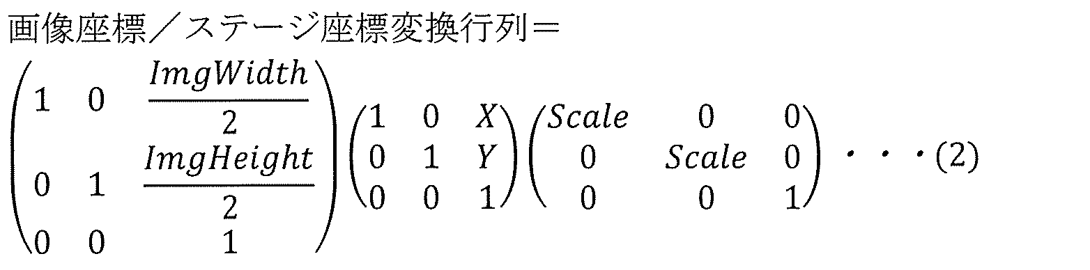
また、図6Bで示すように、マウスカーソル4A04のマウスオーバー時間が一定時間以上になると代表画像を所定のスケールで拡大するためには、上記変換行列に対して所定のスケール制御行列(拡大率:SetScale)を適用する必要がある。
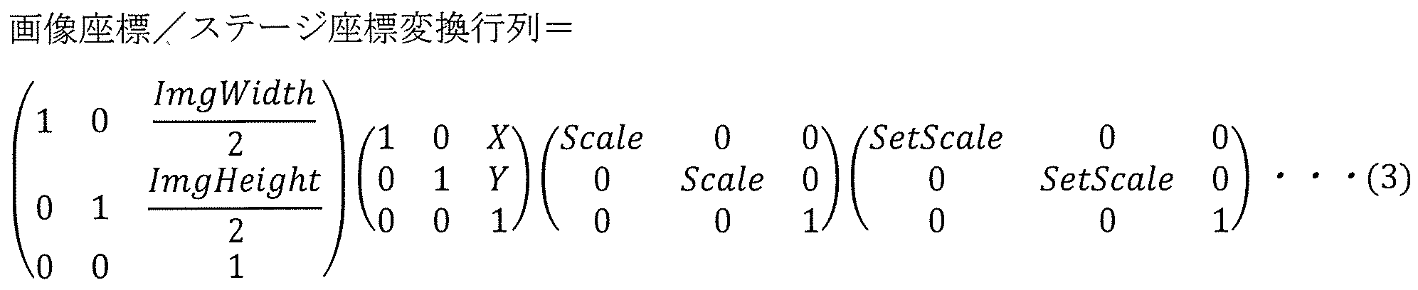
このように、上記式により観察画像座標領域7A01を代表画像表示領域7B01として、ステージ座標領域7A02への変換が可能となる。
図7Cは代表画像表示領域7B01から観察位置表示画面座標領域7C02へのアフィン変換処理を説明する概略図である。図7Cの例では、計算便宜上、観察位置表示画面座標領域7C02も、観察画像座標領域7A01と、ステージ座標領域7A02と同様に、座標系に関してはX軸右方向とY軸下方向を正とし、左上頂点を原点とする。
ステージ座標領域7A02で表示されている代表画像表示領域7B01を、観察位置表示画面座標領域7C02で表示するために、まず両者間のピクセル分解能を一致させる必要があるので、代表画像表示領域7B01に対してスケーリング(拡大率:DisplayScale)を適用する必要がある。
次に、観察位置表示画面2A01における表示位置をオフセット値として適用する必要がある。図7Cの例では、拡大代表画像6B01を観察位置表示画面座標領域7C02の座標(a,b)に表示するので、下記アフィン変換処理で紐づけることが可能である。

また、拡大代表画像6B01を囲む吹き出し枠の付け根は、拡大代表画像6B01の実際の撮像位置(c,d)を指しており、ステージ座標/画面座標変換点線7C01に沿って下記により求めることが可能である。

ここで、観察位置表示画面2A01で表示されている拡大代表画像6B01の表示領域内の位置がダブルクリックされた場合、ダブルクリックされた画面座標(ClickX,ClickY)に対して式(4)の逆変換行列を作用させることにより、対応するステージ座標を求めることが可能となる。

図7A~7Cの例は、ステージ104のx座標とy座標に関するアフィン変換処理例を示しているが、これらの座標に代えて、またはこれらの座標に加えて、R座標、Z座標、T座標、観察位置表示画面2A01の回転方向の座標、等に対して変換処理を行っても良く、この実施例に限るものではない。また、光学系制御装置により荷電粒子線のx座標とy座標におけるシフト及び、走査方向の回転(ラスターローテーション)などに対する変換処理を含めても良い。
(効果)
上記のように、観察位置表示画面2A01で表示されている拡大代表画像6B01の表示領域範囲における任意の位置を指定した場合、指定した位置に正確に移動できるようにステージ座標に変換され、そのステージ座標にステージ104が移動される。本実施例では、マウスオーバーで拡大された代表画像の表示領域に対する操作について記述しているが、代表画像を拡大しなくてもステージ座標の変換を可能とし、本実施例に限るものではない。
上記のように、観察位置表示画面2A01で表示されている拡大代表画像6B01の表示領域範囲における任意の位置を指定した場合、指定した位置に正確に移動できるようにステージ座標に変換され、そのステージ座標にステージ104が移動される。本実施例では、マウスオーバーで拡大された代表画像の表示領域に対する操作について記述しているが、代表画像を拡大しなくてもステージ座標の変換を可能とし、本実施例に限るものではない。
[実施例4]
主な参照図:図8A~8C、図9A~9B
主な内容:ステージの回転を考慮したナビゲーション処理を説明する
主な参照図:図8A~8C、図9A~9B
主な内容:ステージの回転を考慮したナビゲーション処理を説明する
以下、本発明の実施例4について説明する。実施例1~3と共通する部分については、説明を省略する場合がある。
図8A~8Cは、ステージ104の回転を考慮したナビゲーション処理を説明する概略図である。図8Aは、観察位置表示画面2A01のオペレーション操作部8A01とローテーションバー8A10を示している。
ステージ座標入力部8A02は、ステージ104のX、YとR座標に対する操作を可能とする。回転原点入力部8A03は、ステージ104の回転原点を設定することを可能とする。領域設定部8A04は、試料の範囲に対する撮像領域を設定する設定部であり、点指定及び範囲指定を行うことが可能である(図21A~26で後述する)。
制御設定ボタン8A09は、制御設定画面1900(図19参照)を呼出し、荷電粒子線装置100の操作時における各種設定を行う。ローテーションバー8A10は、表示中試料背景画像4A02の回転角度を表示するためのマーカーであり、ステージ104の回転角度に応じて表示角度が変化する。
異なるステージ104の回転角度で撮像された観察画像を代表画像として表示した場合、図8Aに示すように、各観察画像はそれぞれの回転角度に応じて表示される。この際、ステージの回転を考慮するために、以下のように式(3)と式(4)に対して回転変換行列を適用する。ここで、θはステージ104のR座標を表す。


図8Bでは、ステージ座標入力部8A02で、R座標を-45°で設定した場合、観察位置表示画面2A01の表示内容は画面に対して反時計回りに45°回転するため、その角度で撮像された代表画像8A11はまっすぐに表示される。
このように、座標変換処理部1225は、荷電粒子線装置100のステージ回転角度及び回転中心に基づいて座標系の前記相互変換を行う。
ここで、マウスカーソル4A04を代表画像8A11の表示領域範囲で一定時間以上マウスオーバーすると、図8Cに示すように代表画像8A11が拡大される。拡大代表画像8C01の表示領域範囲における任意の位置を指定した場合、指定した位置に選択位置マーカー6C01が表示され、その位置の画面座標が取得される。この場合、式(8)を式(6)に代入した式(9)より、取得された画面座標をステージ座標に変換することが可能になり、ステージ104を正確に位置移動することが可能になる。

図9A~9Bは、回転原点以外の場合におけるステージ104の回転を考慮したナビゲーション処理について説明する概略図である。図9Aに示すように、ステージ104の回転原点中心9A01が、ステージ座標領域7A02の中心以外、例えば(20,10)の位置にある場合、式(3)と式(4)に対して回転原点を考慮した変換行列を作成すれば、異なる回転角度で撮像された代表画像を表示することが可能となる。
ここで、ステージ104を回転すると、図9Bに示すように回転原点中心9A01を中心に観察位置表示画面2A01が回転する。同じように、回転原点を考慮した式(6)を使用すれば、拡大代表画像8C01の表示領域範囲における任意位置の画面座標をステージ座標に変換することが可能になり、ステージ104を正確に位置移動することが可能になる。
(効果)
上記のように、ステージ104の異なる回転角度で撮像された代表画像に対して、回転変換行列を適用することで、観察位置表示画面2A01で表示されている代表画像の表示領域範囲の任意位置を指定しても、実施例3と同様にステージ104をその位置に移動することができるので、試料のナビゲーションに使用することが可能である。さらに、ステージ104の回転原点が(0,0)以外の場合においても、その回転原点を考慮した変換式を作成すれば、同様に試料のナビゲーションが可能である。
上記のように、ステージ104の異なる回転角度で撮像された代表画像に対して、回転変換行列を適用することで、観察位置表示画面2A01で表示されている代表画像の表示領域範囲の任意位置を指定しても、実施例3と同様にステージ104をその位置に移動することができるので、試料のナビゲーションに使用することが可能である。さらに、ステージ104の回転原点が(0,0)以外の場合においても、その回転原点を考慮した変換式を作成すれば、同様に試料のナビゲーションが可能である。
[実施例5]
主な参照図:図10~11B
主な内容:代表画像の拡大表示サイズの消去処理を説明する
主な参照図:図10~11B
主な内容:代表画像の拡大表示サイズの消去処理を説明する
以下、本発明の実施例5について説明する。実施例1~4と共通する部分については、説明を省略する場合がある。
図10のフローチャートを参照し、マウスオーバーによる代表画像の拡大表示の消去処理について説明する。
まず、ステップS1001では、観察位置表示画面2A01において、所定のスケールで拡大された拡大代表画像6B01の表示領域範囲においてマウスカーソル4A04を移動する場合、ステップS1002において、マウスカーソル4A04のいる位置の画面座標を、入力デバイス監視処理部1224が取得し、拡大代表画像6B01の表示領域範囲内であるか否かを判定する。
もし、その画面座標が拡大代表画像6B01の表示領域範囲内であれば、ステップ1004において、拡大代表画像6B01の拡大表示を維持する。
ステップS1002において、もし、マウスカーソル4A04が拡大代表画像の表示領域範囲外に移動されたと判定された場合、ステップ1003において、表示処理部1223が拡大代表画像6B01の拡大表示を消去し、すなわち拡大代表画像6B01の表示サイズを元の代表画像の表示サイズに戻す。
図11A~11Bは、マウスオーバーによる代表画像の拡大表示の消去処理を説明する概略図である。
図11Aに示すように、観察位置表示画面2A01において、マウスカーソル4A04が拡大代表画像6B01の表示領域範囲外に移動された場合、図11Bに示すように表示処理部1223は拡大代表画像6B01の拡大表示を消去し、代表画像4A01となるように表示サイズを元通りに戻す。
このように、マウスカーソル4A04の位置が拡大代表画像6B01の表示領域範囲外であることを入力デバイス監視処理部1224が検知すると、表示処理部1223は、所定のスケールで拡大して表示されていた拡大代表画像6B01を、元のスケールで表示し直す。
(効果)
上記のように、代表画像4A01の表示領域範囲を一定時間以上にマウスオーバーすることにより、所定のスケールで拡大表示された拡大代表画像6B01は、観察位置表示画面2A01で大きく表示スペースを占有するため、試料の異なる範囲の情報確認の妨げになることがある。このようことを防ぐために、拡大表示された拡大代表画像6B01の表示領域範囲からマウスカーソル4A04が移動された場合、拡大代表画像6B01の拡大表示を消去することにより、観察位置表示画面2A01で確認できる情報が増える。
上記のように、代表画像4A01の表示領域範囲を一定時間以上にマウスオーバーすることにより、所定のスケールで拡大表示された拡大代表画像6B01は、観察位置表示画面2A01で大きく表示スペースを占有するため、試料の異なる範囲の情報確認の妨げになることがある。このようことを防ぐために、拡大表示された拡大代表画像6B01の表示領域範囲からマウスカーソル4A04が移動された場合、拡大代表画像6B01の拡大表示を消去することにより、観察位置表示画面2A01で確認できる情報が増える。
[実施例6]
主な参照図:図12~13B
主な内容:代表画像の表示領域内におけるマウスドラッグ操作によるナビゲーション処理
主な参照図:図12~13B
主な内容:代表画像の表示領域内におけるマウスドラッグ操作によるナビゲーション処理
以下、本発明の実施例6について説明する。実施例1~5と共通する部分については、説明を省略する場合がある。
図12のフローチャートを参照し、拡大代表画像6B01の表示領域範囲内におけるマウスドラッグ操作によるナビゲーション処理について説明する。
ステップS1201~ステップS1204は実施例3(図5参照)と同一で良いため、重複する説明は省略する。
ステップS1205では、ユーザは、拡大された拡大代表画像6B01の表示領域範囲内任意の位置を始点とし、その位置からマウスドラッグを行う。ステップ1206において、マウスドラッグ操作が終了した位置を終点とすると、入力デバイス監視処理部1224は、マウスドラッグの始点と終点の画面座標を取得し、表示処理部1223へ渡す。表示処理部1223は始点と終点の画面座標を使用し、拡大代表画像6B01の表示領域範囲で矩形マーカーを描画する。
ステップS1207では、表示処理部1223が矩形マーカー中心位置の画面座標を取得し、ステップS1208で座標変換処理部1225によりアフィン変換処理で対応するステージ座標へ変換され、情報処理部1221に送信される。
次に、ステップS1209において、情報処理部1221は、取得したステージ座標に基づいてステージ制御信号を生成し、それをステージ制御装置130に出力する。ステージ制御装置130は、ステージ制御信号に示される移動位置にステージ104を駆動する。
ステップS1210では、表示処理部1223が矩形マーカーの左上頂点と右上頂点の画面座標を取得し、座標変換処理部1225によりアフィン変換処理でそれぞれ対応するステージ座標へ変換され、情報処理部1221に送信される。
ステップS1211では、情報処理部1221において、左上頂点と右上頂点のステージ座標間の差分を求めた後、差分に対する所定の基準寸法の比率計算より倍率を求める。ステップS1212では、情報処理部1221は求まった倍率に基づいて光学制御信号を生成し、それを光学系制御装置170に出力する。光学系制御装置170は、光学制御信号に示される倍率を再現するように電子線の走査範囲を制御する。
このように、座標変換処理部1225は、左上頂点位置および右上頂点位置と、拡大代表画像6B01の中心位置との画面座標をステージ座標系へ変換し、左上頂点位置および右上頂点位置のステージ座標間差分に対する所定の基準寸法の比率から倍率を計算する。そして、座標変換処理部1225は、観察支援装置に、中心位置のステージ座標および倍率を再現させる。
図13A~13Bは、拡大代表画像6B01の表示領域範囲内におけるマウスドラッグ操作によるナビゲーション処理について説明する概略図である。
図13Aの例では、拡大代表画像6B01の表示領域範囲において、2個の円形構造物うち、右下の円形構造物を中心にマウスドラッグすると、マウスドラッグが開始される位置をマウスカーソル4A04のドラッグ始点座標13A01とし、マウスドラッグが終了した位置をドラッグ終点座標13A02とする。この場合、ドラッグ始点座標13A01とドラッグ終点座標13A02に基づいて、拡大代表画像6B01の表示領域範囲で矩形マーカー13A03が描画される。
図13Bに示すように、矩形マーカー13A03の中心位置の画面座標はアフィン変換処理によりステージ座標へ変換され、そのステージ座標に移動するようにステージ104が制御される。同様に、矩形マーカーの左上頂点位置および右上頂点位置の画面座標はアフィン変換でそれぞれ対応するステージ座標へ変換された後、ステージ座標間の差分が求められる。
この差分に対する所定の基準寸法の比率が求まると、倍率が算出され、観察画像表示画面4A07の画面倍率へ適用される。このように、矩形マーカー13A03と対応する位置と倍率で、観察画像表示画面4A07で視野が再現される。
このように、入力デバイス監視処理部1224は、拡大代表画像6B01の表示領域範囲内における入力操作の始点位置および終点位置を取得し、表示処理部1223は、拡大代表画像6B01の表示領域に、始点位置および終点位置に対応する矩形マーカーを表示する。
(効果)
上記のように、観察位置表示画面2A01で表示されている拡大代表画像6B01の表示領域範囲において任意のドラッグ始点位置とドラッグ終点位置により作成される矩形マーカーと対応する位置と倍率の視野を再現することが可能なため、直感的でかつ容易な操作で目的の視野へナビゲートすることができる。
上記のように、観察位置表示画面2A01で表示されている拡大代表画像6B01の表示領域範囲において任意のドラッグ始点位置とドラッグ終点位置により作成される矩形マーカーと対応する位置と倍率の視野を再現することが可能なため、直感的でかつ容易な操作で目的の視野へナビゲートすることができる。
本実施例では、マウスドラッグによる操作で矩形領域の作成について記述しているが、マウスドラッグ以外で始点と終点の座標を取得する手段があれば同じようなことを実現できるので、本実施例の手法に限るものではない。
[実施例7]
主な参照図:図14~15D
主な内容:代表画像の表示領域のデジタルズーム操作によるナビゲーション処理
主な参照図:図14~15D
主な内容:代表画像の表示領域のデジタルズーム操作によるナビゲーション処理
以下、本発明の実施例7について説明する。実施例1~6と共通する部分については、説明を省略する場合がある。
図14のフローチャートを参照し、拡大代表画像6B01の表示領域範囲におけるデジタルズーム操作によるナビゲーション処理を説明する。
入力デバイス(マウス等)は、回転部材(以下では例としてマウスホイール)を備える。
ステップS1401では、ユーザは、拡大代表画像6B01の表示領域範囲内においてマウスホイールの回転操作を行う。そうすると、入力デバイス監視処理部1224はマウスホイールの回転方向および回転量を取得し、それを座標変換処理部1225へ出力する。座標変換処理部1225において、マウスホイールの回転方向および回転量に応じ、適切なスケール変換行列を作成する。
このように、入力デバイス監視処理部1224は、マウスカーソル4A04の位置が、拡大代表画像6B01の表示領域範囲内にある場合に、マウスホイールの回転方向と回転量を取得する。そして、座標変換処理部1225は、マウスホイールの回転方向と回転量に応じ、スケール変換行列を作成する。
ステップS1402では、表示処理部1223は、このスケール変換行列を適用し、拡大代表画像6B01の表示領域範囲において、マウスカーソル4A04を中心にデジタルズームイン/アウトし、表示領域範囲を拡大/縮小する。このように、表示処理部1223は、マウスカーソル4A04の位置を中心に、スケール変換行列を適用することで拡大代表画像6B01をデジタルズームする。
次に、ステップS1403では、拡大代表画像6B01のデジタルズームされた表示領域範囲で任意の位置をユーザがマウスカーソル4A04でダブルクリックすると、ステップS1404において、その位置の画面座標を入力デバイス監視処理部1224が取得し、座標変換処理部1225に出力する。
ステップS1405において、座標変換処理部1225により画面座標が対応するステージ座標に変換され、情報処理部1221に送信される。次に、ステップS1406において、情報処理部1221は、取得したステージ座標に基づいてステージ制御信号を生成し、それをステージ制御装置130に出力する。ステージ制御装置130は、ステージ制御信号に示される移動位置にステージ104を駆動する。
続いて、ステップS1407では、表示処理部1223は拡大代表画像6B01のデジタルズームされた表示領域範囲における左上頂点及び右上頂点の画面座標を取得し、座標変換処理部1225へ出力する。これらは、アフィン変換でそれぞれ対応するステージ座標へ変換され、情報処理部1221に送信される。
ステップS1408では、情報処理部1221において、左上頂点と右上頂点のステージ座標間の差分を求めた後、差分に対する所定の基準寸法の比率計算から倍率を求める。ステップS1409では、情報処理部1221は求まった倍率に基づいて光学制御信号を生成し、それを光学系制御装置170に出力する。光学系制御装置170は、光学制御信号に示される倍率を再現するように電子線の走査範囲を制御する。
このように、入力デバイス監視処理部1224は、デジタルズームされた拡大代表画像6B01の表示領域範囲内においてマウスカーソル4A04の位置を取得する。座標変換処理部1225は、マウスカーソル4A04の位置をステージ座標系へ変換し、デジタルズームされた拡大代表画像6B01の表示領域範囲における左上頂点及び右上頂点の画面座標をそれぞれ対応するステージ座標系へ変換し、左上頂点と右上頂点のステージ座標間の差分を求めた後、当該差分に対する所定の基準寸法の比率から倍率を計算する。条件制御部1226は、荷電粒子線装置100のステージ104を、ステージ座標系に変換されたマウスカーソル4A04の位置に移動させるとともに、計算された前記倍率を再現する。
図15A~15Dは、拡大代表画像6B01の表示領域範囲におけるデジタルズーム操作によるナビゲーション処理を説明する概略図である。
図15Aの例では、拡大代表画像6B01の表示領域範囲において、マウスホイールの回転などで、マウスカーソルを中心にデジタルズームが行われる。また、拡大代表画像6B01のデジタルズームスケールが分かるように、その左側にデジタルズームスケールバー15A01が表示され、デジタルズーム率は元表示スケール(min)から所定の最大デジタルズームインスケール(max)までとする。
図15Bの例では、2個の円形構造物の間でマウスホイールが回転され、その回転量に応じて拡大代表画像6B01の表示領域範囲がデジタルズームされる。また、それとともに、デジタルズームスケールバー15A01のスライダもそれ応じたデジタルズーム率に移動される。
このように、表示処理部1223は、デジタルズームされた拡大代表画像6B01の左側に、デジタルズームスケールバーを表示し、デジタルズーム率に応じてデジタルズームスケールバーのスライダの位置を変更する。これによってユーザはデジタルズーム率を容易に変更できる。
さらに、図15Cに示すように、デジタルズームされた状態の拡大代表画像6B01の表示領域内でユーザがマウスカーソル4A04を上方向に移動させ、ダブルクリックする。そうすると、クリックされた位置の画面座標がステージ座標に変換され、その位置にステージ104が移動される。
また、拡大代表画像6B01のデジタルズームされた表示領域範囲における左上頂点及び右上頂点の画面座標がそれぞれ対応するステージ座標へ変換され、ステージ座標間の差分に対する所定の基準寸法の比率計算から倍率を求め、観察画像表示画面4A07の画面倍率へ適用される。
最後に、図15Dに示すように、代表画像の表示領域範囲に、デジタルズームされた範囲に相当する矩形マーカー13B01が描画される。
(効果)
上記のように、観察位置表示画面2A01で表示中の拡大代表画像6B01の表示領域範囲をさらにデジタルズームすることで、さらに精度良く試料のナビゲーションが可能となる。
上記のように、観察位置表示画面2A01で表示中の拡大代表画像6B01の表示領域範囲をさらにデジタルズームすることで、さらに精度良く試料のナビゲーションが可能となる。
また、デジタルズームした範囲に相当する倍率が適用されるため、ユーザの操作意図との一致性を維持できるため、直感的な操作が可能となる。
本実施例では、マウスホイールの回転によるデジタルズームについて記述しているが、マウスホイールの回転以外でデジタルズームスケールを変更する手段があれば同じようなことを実現できるので、本実施例の手法に限るものではない。
[実施例8]
主な参照図:図16A~16B
主な内容:観察位置表示部の表示倍率の変更を説明する
主な参照図:図16A~16B
主な内容:観察位置表示部の表示倍率の変更を説明する
以下、本発明の実施例8について説明する。実施例1~7と共通する部分については、説明を省略する場合がある。
図16A~16Bは、観察位置表示部1252(図1参照)の画面場率の変更に関する処理を説明する概略図である。
図16Aの例では、観察位置表示部1252の一例である観察位置表示画面2A01において、ユーザは、拡大代表画像6B01の表示領域範囲で表示されている2個の円形構造物のうち、左上の円形構造物の中心をダブルクリックする。そうすると、図16Bにおいて、前述した実施例2~実施例7で記載された内容と同じように、その中心の画面座標がアフィン変換処理によりステージ座標に変換され、ステージ104がそのステージ座標に移動するように制御される。また、拡大代表画像6B01の付帯情報ファイルから撮像倍率を取得し、観察画像表示画面4A07の画面倍率に適用する。
ここで、観察位置表示画面2A01の表示位置が、ダブルクリックされた画面座標に一致するように移動され、画面倍率も拡大代表画像6B01の撮像倍率と一致するように画面のスケール変換が行われる。図16Bの例では、左上の円形構造物中心が観察位置表示画面2A01の中心になり、画面倍率は代表画像の撮像倍率、例えば5000倍に切換わっている。
このように、マウスカーソル4A04の位置が、デジタルズームされた拡大代表画像6B01の表示領域範囲内にある場合に、表示処理部1223は、拡大代表画像6B01のうち表示領域範囲に対応する範囲を、マウスカーソル4A04の位置を中心とする範囲に切り換えるとともに、拡大代表画像6B01の撮像時の倍率を観察位置表示部1252の倍率として適用する。
(効果)
上記のように、観察位置表示画面2A01で表示されている拡大代表画像6B01の表示領域範囲における任意の位置をユーザが指定した場合、観察位置表示画面2A01がその位置や適切な画面倍率に切換わるため、観察位置表示画面2A01画面を操作する手間を省略でき、操作性の向上につながる。
上記のように、観察位置表示画面2A01で表示されている拡大代表画像6B01の表示領域範囲における任意の位置をユーザが指定した場合、観察位置表示画面2A01がその位置や適切な画面倍率に切換わるため、観察位置表示画面2A01画面を操作する手間を省略でき、操作性の向上につながる。
ただし、ユースケースにより観察位置表示画面2A01の自動切り換わりが逆に操作性を悪化させる場合があるので、制御設定ボタン8A09(図8A参照)から呼び出される、制御設定画面1900(図19参照)の画面表示制御部1903において、画面倍率と画面位置の連動を切り換えることを可能とする。
また、本実施例では、観察位置表示画面2A01の画面倍率を拡大代表画像6B01の撮像倍率に切り替えると記述しているが、それ以外の適切な画面倍率に切り替えて良く、本実施例に限定して解釈してはならない。
[実施例9]
主な参照図:図17~19
主な内容:荷電粒子線装置の観察条件の変更処理を説明する
主な参照図:図17~19
主な内容:荷電粒子線装置の観察条件の変更処理を説明する
以下、本発明の実施例9について説明する。実施例1~8と共通する部分については、説明を省略する場合がある。
図17のフローチャートを参照し、荷電粒子線装置100の観察条件の変更処理について説明する。
ステップS1701において、例えば、ステージ104の現在位置が代表画像Aの表示領域範囲にあり、観察条件Aで視野を観察しているとする。ステップS1702において、ユーザは、ステージ104を手動で操作するか、もしくは実施例2~8のナビゲーション処理を利用して、ステージ104を代表画像Aの表示領域範囲から代表画像Bの表示領域範囲内に移動する。
ステップS1703において、ステージ104の現在座標を情報処理部が常に管理しているため、ステージ104が代表画像Bの表示領域範囲に入っていることを検知した場合、代表画像Bの付帯情報ファイルから観察条件Bを取得し、ステップS1704において観察条件を荷電粒子線装置100に適用し、観察条件Aから観察条件Bへ切り替える。
このように、条件制御部1226は、荷電粒子線装置100に代表画像Bの観察条件を再現させる。
なお、本実施例で記載されている「観察条件」とは、荷電粒子線の加速電圧、ビーム強度(コンデンサに流す電流の強度)、ビーム走査範囲(倍率)、ビームのワーキングディスタンス(WD)、画質(コントラスト、ブライトネス)、試料から検出される信号種類(反射電子、2次電子、後方散乱電子、非弾性散乱電子、オージェ電子、カソードルミネッセンス、X線)、のうち少なくとも1つを含む。
図18A~18Cは、荷電粒子線装置100の観察条件の変更処理について説明する概略図である。
図18Aの例では、ステージ104の現在位置が代表画像A18A01の表示領域範囲にあり、荷電粒子線装置100に観察条件A18A03が適用されており、観察画像表示画面4A07に示すような視野が映っている。
ここで、代表画像B18A02にマウスカーソル4A04を一定時間以上マウスオーバーすると、図18Bに示すように、代表画像B18A02が所定のスケールで拡大表示される。拡大代表画像18B01で表示されている星形構造物の右上突出部の頂点をダブルクリックすると、実施例3のナビゲーション処理によりクリックした位置にステージ104が移動する。
ステージ104の現在位置が、代表画像B18A02または拡大代表画像18B01の表示領域範囲に入っていることが検知されたら、図18Cに示すように、荷電粒子線装置100の観察条件が観察条件A18A03から観察条件B18C01に切り換わり、観察画像表示画面4A07に示すように視野の見え方が変化する。
(効果)
上記のように、試料のナビゲーションを行っている際、観察部位により観察条件を自動的に切り換えると、観察条件の手動調整による手間を省略できるため、操作性の向上につながる。
上記のように、試料のナビゲーションを行っている際、観察部位により観察条件を自動的に切り換えると、観察条件の手動調整による手間を省略できるため、操作性の向上につながる。
ただし、ユースケースにより観察条件の自動切り換わりが逆に操作性を悪化させる場合があるので、制御設定ボタン8A09から呼び出される、制御設定画面1900(図19参照)の観察条件設定部1901において、検出信号の種類、加速電圧、強度、ワーキングディスタンスと倍率の再現実施を切り換えることを可能とする。また、座標条件設定部1902において、座標の再現条件を切り替えることを可能としてもよい。
また、本実施例では、観察位置表示画面2A01の観察条件からステージ104の現在位置を含んでいる代表画像の観察条件へと切り替えると記述しているが、本実施例で定義した観察条件以外の条件に切り替えて良く、本実施例に限定して解釈してはならない。
[実施例10]
主な参照図:図20~21B、図25
主な内容:代表画像を利用した連続撮像設定手順(点指定)を説明する
主な参照図:図20~21B、図25
主な内容:代表画像を利用した連続撮像設定手順(点指定)を説明する
以下、本発明の実施例10について説明する。実施例1~9と共通する部分については、説明を省略する場合がある。
図20のフローチャートを参照し、代表画像の表示領域範囲で指定した座標に基づく連続撮像設定手順について説明する。
ステップS2001において、拡大代表画像の表示領域範囲内で任意の位置をユーザがクリックすると、入力デバイス監視処理部1224がクリックした位置の画面座標を取得し、表示処理部1223に出力する。ステップS2002において、表示処理部1223は受け取った画面座標に基づき、拡大代表画像6B01の表示領域範囲の対応位置に選択位置マーカー6C01を表示する。
ステップS2003において、選択位置マーカー6C01の画面座標を中心に、連続撮像する画像群の倍率、画像間の重複量、X,Y方向におけるそれぞれの撮像枚数、を設定する。S2004において、情報処理部1221はこれらの設定情報を表示処理部1223に出力する。表示処理部1223は設定情報に基づき、連続撮像する画像のそれぞれを矩形シンボルとして表し、X,Y方向に一部重複させつつ撮像枚数だけ並べて拡大代表画像6B01の表示領域範囲内に表示する。
図21A~21Bは、代表画像の表示領域範囲で指定した座標に基づく連続撮像設定手順を説明する概略図である。
図21Aの例では、領域設定部8A04の座標指定実行ボタン8A05をユーザがクリックすると、観察位置表示画面2A01は座標指定による連続撮像領域の設定が可能なモードに切換わる。このモードで、拡大代表画像6B01の表示領域範囲において、2個の円形構造物のうち、左上の円形構造物の中心をユーザがマウスカーソル4A04で指定した場合、その位置に選択位置マーカー6C01が表示される。
次に、座標指定設定ボタン8A06のクリックにより、図25に示すような座標指定設定画面2500が呼び出される。座標指定設定画面2500において、選択位置マーカー6C01を中心に、倍率設定部2501で連続撮像する画像群の倍率を設定し、重複量設定部2502で画像間の重複量を設定し、枚数設定部2503でX,Y方向におけるそれぞれの撮像枚数を設定することが可能である。
図21Bに示すように、表示処理部1223はこれらの設定情報に基づき、選択位置マーカー6C01を中心に連続撮像する画像を矩形シンボルとし、X,Y方向において設定枚数分で拡大代表画像6B01の表示領域範囲にリアルタイムで表示する。
このように、表示処理部1223は、拡大代表画像6B01の表示領域範囲内において、マウスカーソル4A04を介して指定された指定位置を位置マーカーで表示する。情報処理部1221は、指定位置に応じて連続撮像の設定情報を生成する。設定情報は、倍率、画像間の重複量、X方向における撮像枚数、および、Y方向における撮像枚数を含む。表示処理部1223は、設定情報に基づき、連続撮像に係る画像群を矩形シンボル群として表示する。
とくに、表示処理部1223は、拡大代表画像6B01の表示領域範囲内において、マウスカーソル4A04を介して指定された指定中心位置を位置マーカーで表示する。情報処理部1221は、この指定中心位置を中心として設定情報を生成する。
図21Bの例では、連続撮像する画像を表すのに、矩形で半透明のシンボルを使用しているが、矩形でないシンボルまたは不透明なシンボルなどを使用してもよく、本実施例に限定して解釈してはならない。
また、本実施例では、指定座標を中心に連続撮像画像群21B01を設定すると記載しているが、指定座標を連続撮像画像群21B01の最も左上の一枚の画像の中心座標としてもよく、本実施例に限定して解釈してはならない。
(効果)
上記のように、拡大代表画像6B01を利用した連続撮像領域の設定の実現により、観察位置表示画面2A01の視野(画面倍率に対する観察位置表示画面2A01の寸法の比率から計算)が、連続撮像を設定したい試料対象領域の視野と極端に離れていても、観察位置表示画面2A01の視野と位置を手動で切り替えるなど、対象領域探しの手間を省略することができ、操作性の向上に貢献できる。
上記のように、拡大代表画像6B01を利用した連続撮像領域の設定の実現により、観察位置表示画面2A01の視野(画面倍率に対する観察位置表示画面2A01の寸法の比率から計算)が、連続撮像を設定したい試料対象領域の視野と極端に離れていても、観察位置表示画面2A01の視野と位置を手動で切り替えるなど、対象領域探しの手間を省略することができ、操作性の向上に貢献できる。
また、設定した連続撮像領域が指定座標に対してどのように撮像されるかを矩形シンボルとして視覚化されているため、試料の対象領域に対して直感的に設定を行うことでき、さらに操作性の向上につながる。
[実施例11]
主な参照図:図22~23E、図26
主な内容:代表画像を利用した連続撮像設定手順(範囲指定)を説明する
主な参照図:図22~23E、図26
主な内容:代表画像を利用した連続撮像設定手順(範囲指定)を説明する
以下、本発明の実施例11について説明する。実施例1~10と共通する部分については、説明を省略する場合がある。
図22のフローチャートを参照し、代表画像の表示領域範囲で指定した範囲における連続撮像設定手順について説明する。
ステップS2201において、拡大代表画像6B01の表示領域範囲内において、ユーザが複数任意の位置をクリックすると、入力デバイス監視処理部1224がそれぞれクリックした位置の画面座標を取得し、表示処理部1223に出力する。表示処理部1223は、受け取った画面座標に基づき、それぞれの位置に選択位置マーカー6C01を表示する。
ステップS2202において、クリック操作を完了した際に、表示処理部1223はそれぞれ複数の選択位置マーカー6C01を順番につなぎ、最終的には各位置を頂点とするポリゴンを作成し、拡大代表画像6B01の表示領域範囲に表示する。このようにして、ユーザは任意形状のポリゴンを形成することができる。
ステップS2203において、表示処理部1223はポリゴンの全体を含む最小の矩形(対角線の長さが最小となる矩形)を作成する。また、その矩形の4頂点の画面座標を計算し、情報処理部1221に出力する。
続いて、ステップS2204において、ユーザが撮像倍率、画像間重複量を設定する。ポリゴンを囲む矩形領域が埋まるように撮像枚数を情報処理部1221が計算し、連続撮像される画像を矩形シンボルとして表示する。なお、撮像倍率と画像間重複量が設定されれば、一枚の画像の視野を計算できる。
また、ポリゴンを囲む矩形の任意の2頂点(例えば左上頂点および右上頂点であるが、左上頂点および右下頂点、左下頂点および右下頂点、左上頂点および左下頂点、等であってもよい)の画面座標をアフィン変換でステージ座標に変換し、2頂点のステージ座標間の差分を求めれば、ポリゴンを囲む矩形のサイズが求まる。このように、ポリゴンを囲む矩形領域が埋まるように撮像枚数を計算することが可能である。
ステップS2205において、連続撮像画像群を左上から右下まで、一枚ずつポリゴンとの重なり判定を行う。なお、連続撮像画像群とポリゴンとの重なり判定精度を高めるために、画面座標系で実施するのではなく、任意形状のポリゴンの領域をステージ座標系に変換してから実施するものとする。
ステップS2206において、情報処理部1221はポリゴンと撮像画像との間で重なっている領域があるか否かの判定処理を実行する。もし、両者間に重なり領域があると判定された場合、ステップS2207において、情報処理部1221はその画像を連続撮像の対象画像と設定し、次の画像との重なり判定を繰り返す。
ステップS2206において、もし両者間に重なり領域がないと判定された場合、情報処理部1221はその画像を連続撮像の対象画像ではないと設定し、次の画像との重なり判定を繰り返す。
図23A~23Eは、代表画像の表示領域範囲で指定した範囲における連続撮像設定手順について説明する概略図である。
図23Aの例では、領域設定部8A04の範囲指定実行ボタン8A07をクリックすると、観察位置表示画面2A01は範囲指定による連続撮像領域の設定が可能なモードに切換わる。このモードで、拡大代表画像6B01の表示領域範囲において、2個の円形構造物のうち、左上の円形構造物の周辺で、複数任意の位置を順番に指定していくと、それぞれの位置に選択位置マーカー6C01が表示される。
図23Bでは、ユーザがクリック操作の完了を指示した際に、表示処理部1223はそれぞれ複数の選択位置マーカー6C01を順番につなぎ、最終的にはポリゴン23B01を作成し、拡大代表画像6B01の表示領域範囲に表示する。
このように、表示処理部1223は、各指定位置を線で接続してポリゴンを表示する。これによってユーザは容易にポリゴンの形状を指定することができる。
次に、範囲指定設定ボタン8A08のクリックにより、図26に示すように範囲指定設定画面2600が呼び出される。範囲指定設定画面2600において、倍率設定部2501で連続撮像する画像群の倍率を設定し、重複量設定部2502で画像間の重複量を設定すると、一枚の画像の視野を計算できる。
また、図23Dに示すように、ポリゴン23B01を囲む矩形23D01の頂点(例えばX方向の2頂点、または対角に位置する2頂点)の画面座標をアフィン変換でステージ座標に変換し、2頂点のステージ座標間の差分を求めれば、ポリゴンを囲む矩形のサイズが求まる。
次に、ポリゴンと撮像画像との間で重なっている領域があるか否かの判定処理を実行すれば、連続撮像の対象画像の自動設定を実現することができる。本実施例の場合であると、図23Eのような連続撮像画像群23C01が設定され、連続撮像画像の枚数は範囲指定設定画面2600の合計枚数表示部2601にて表示される。
このように、表示処理部1223は、拡大代表画像6B01の表示領域範囲内において、マウスカーソル4A04を介して指定された2以上の指定位置を位置マーカーで表示する。情報処理部1221は、各指定位置に応じて連続撮像の設定情報を生成する。表示処理部1223は、設定情報に基づき、連続撮像に係る画像群を矩形シンボル群として表示する。
また、情報処理部1221は、設定情報に含まれる倍率および画像間の重複量に基づき、一枚の画像の視野を計算する。次に、情報処理部1221は、ポリゴンを囲む矩形の2頂点のステージ座標間の差分から、ポリゴンを囲む矩形のサイズを計算する。次に、情報処理部1221は、一枚の画像の視野と、矩形のサイズとに基づき、矩形の領域が埋まるように画像の枚数を計算する。次に、情報処理部1221は、連続撮像に係る画像群と、ポリゴンとの間での重なり判定結果に基づき、連続撮像に係る画像群のうち1以上の画像を、撮像すべき画像として選択する。このような処理によれば、必要な領域のみを効率的に撮像することができる。
次に、連続撮像画像群23C01をアフィン変換で画面座標系に変換すると、図23Cに示すように、拡大代表画像6B01の表示領域範囲において対象画像が矩形シンボルとして表示される。
図23Cおよび23Dの例では、連続撮像する画像を表すのに、矩形で半透明のシンボルを使用しているが、矩形でないシンボルまたは不透明なシンボルを使用してもよく、本実施例に限定して解釈してはならない。
また、本実施例では、任意形状のポリゴンと画像を表す矩形シンボルとの領域重なり判定を、ステージ座標系で行っているが、観察位置表示画面2A01において画面座標系で判定を行っても良く、本実施例に限定して解釈してはならない。
また、本実施例では、X、Y座標の連続撮像領域の設定について記述しているが、設定した領域の回転角度を変えても良く、本実施例に限定して解釈してはならない。
例えば、図24Aに示すように、ポリゴン23B01をユーザが選択すると、ポリゴンを囲む矩形として、領域範囲矩形枠24A01が表示される。領域範囲矩形枠24A01は、回転操作部24A02を有する。ユーザが領域範囲矩形枠24A01の回転操作部24A02を掴んだまま回転操作(例えば時計回り)を実行すれば、図24Bに示すように、ポリゴン23B01が時計回りに回転する。すなわち、回転操作部24A02に対してマウスカーソル4A04を介した操作が行われると、当該操作に応じてポリゴンが回転する。このような処理によれば、ユーザは撮像対象領域をより自由に指定できる。
最後に、図24Cに示すように、連続撮像画像群22A03を表す画像矩形シンボルは回転した状態で設定される。
本実施例では、ポリゴンに対して回転操作を行うことについて記述しているが、ポリゴンに対してサイズと位置の変更などを行っても良く、本実施例に限定して解釈してはならない。
(効果)
上記のように、拡大代表画像6B01を利用した任意形状の連続撮像領域の設定の実現により、観察位置表示画面2A01の視野(画面倍率に対する観察位置表示画面2A01の寸法の比率から計算される)が、連続撮像を設定したい試料対象領域の視野と極端に異なっていても、観察位置表示画面2A01の視野と位置を手動で切り替えるなど、対象領域探しの手間を省略することができ、操作性の向上に貢献できる。
上記のように、拡大代表画像6B01を利用した任意形状の連続撮像領域の設定の実現により、観察位置表示画面2A01の視野(画面倍率に対する観察位置表示画面2A01の寸法の比率から計算される)が、連続撮像を設定したい試料対象領域の視野と極端に異なっていても、観察位置表示画面2A01の視野と位置を手動で切り替えるなど、対象領域探しの手間を省略することができ、操作性の向上に貢献できる。
また、設定した連続撮像領域が指定座標に対してどのように撮像されるかが矩形シンボルとして視覚化されているため、試料の対象領域に対して直感的に設定を行うことでき、さらに操作性の向上につながる。
100…荷電粒子線装置
101…試料室
102…荷電粒子線光学系
103…試料台
104…ステージ
105…検出器
106…光学カメラ
107…真空ポンプ
108…試料
110…荷電粒子線撮像装置
111…メモリ
120…演算制御部
121…CPU
122…主記憶装置
1221…情報処理部
1222…代表画像登録処理部
1223…表示処理部
1224…入力デバイス監視処理部
1225…座標変換処理部
1226…条件制御部
123…二次記憶装置
124…入力部
125…表示部
1251…観察画像表示部
1252…観察位置表示部
130…ステージ制御装置
131…座標記憶部
132…制御部
133…駆動部
140…真空制御装置
141…メモリ
150…光学撮像装置
151…メモリ
161…荷電粒子源
162…コンデンサーレンズ
163…偏向器
164…対物レンズ
170…光学系制御装置
171…メモリ
2A01…観察位置表示画面
2A02…倍率拡大ボタン
2A03…倍率縮小ボタン
2A04…倍率リセットボタン
2A05…倍率表示部
2A06…表示画像
2B01…代表画像
2E01…補助表示器
4A01…代表画像
4A02…表示中試料背景画像
4A03…吹き出し
4A04…マウスカーソル(カーソル)
4A05…中心部十字点線
4A06…観察視野破線枠
4A07…観察画像表示画面
4D01…付帯情報ファイル
4E01…注目画面座標領域
4E02…注目画面座標
4E03…座標配列
4F01…対応付けテーブル
6B01…拡大代表画像
6C01…選択位置マーカー
7A01…観察画像座標領域
7A02…ステージ座標領域
7A03…画像座標/ステージ座標変換点線
7B01…代表画像表示領域
7C01…ステージ座標/画面座標変換点線
7C02…観察位置表示画面座標領域
8A01…オペレーション操作部
8A02…ステージ座標入力部
8A03…回転原点入力部
8A04…領域設定部
8A05…座標指定実行ボタン
8A06…座標指定設定ボタン
8A07…範囲指定実行ボタン
8A08…範囲指定設定ボタン
8A09…制御設定ボタン
8A10…ローテーションバー
8A11…代表画像
8C01…拡大代表画像
9A01…回転原点中心
13A01…ドラッグ始点座標
13A02…ドラッグ終点座標
13A03…矩形マーカー
13B01…矩形マーカー
15A01…デジタルズームスケールバー
18A01…代表画像A
18A02…代表画像B
18A03…観察条件A
18B01…拡大代表画像
18C01…観察条件B
1900…制御設定画面
1901…観察条件設定部
1902…座標条件設定部
1903…画面表示制御部
21B01…連続撮像画像群
22A03…連続撮像画像群
23B01…ポリゴン
23C01…連続撮像画像群
23D01…ポリゴンを囲む矩形
24A01…領域範囲矩形枠
24A02…回転操作部
2500…座標指定設定画面
2501…倍率設定部
2502…重複量設定部
2503…枚数設定部
2600…範囲指定設定画面
2601…合計枚数表示部
101…試料室
102…荷電粒子線光学系
103…試料台
104…ステージ
105…検出器
106…光学カメラ
107…真空ポンプ
108…試料
110…荷電粒子線撮像装置
111…メモリ
120…演算制御部
121…CPU
122…主記憶装置
1221…情報処理部
1222…代表画像登録処理部
1223…表示処理部
1224…入力デバイス監視処理部
1225…座標変換処理部
1226…条件制御部
123…二次記憶装置
124…入力部
125…表示部
1251…観察画像表示部
1252…観察位置表示部
130…ステージ制御装置
131…座標記憶部
132…制御部
133…駆動部
140…真空制御装置
141…メモリ
150…光学撮像装置
151…メモリ
161…荷電粒子源
162…コンデンサーレンズ
163…偏向器
164…対物レンズ
170…光学系制御装置
171…メモリ
2A01…観察位置表示画面
2A02…倍率拡大ボタン
2A03…倍率縮小ボタン
2A04…倍率リセットボタン
2A05…倍率表示部
2A06…表示画像
2B01…代表画像
2E01…補助表示器
4A01…代表画像
4A02…表示中試料背景画像
4A03…吹き出し
4A04…マウスカーソル(カーソル)
4A05…中心部十字点線
4A06…観察視野破線枠
4A07…観察画像表示画面
4D01…付帯情報ファイル
4E01…注目画面座標領域
4E02…注目画面座標
4E03…座標配列
4F01…対応付けテーブル
6B01…拡大代表画像
6C01…選択位置マーカー
7A01…観察画像座標領域
7A02…ステージ座標領域
7A03…画像座標/ステージ座標変換点線
7B01…代表画像表示領域
7C01…ステージ座標/画面座標変換点線
7C02…観察位置表示画面座標領域
8A01…オペレーション操作部
8A02…ステージ座標入力部
8A03…回転原点入力部
8A04…領域設定部
8A05…座標指定実行ボタン
8A06…座標指定設定ボタン
8A07…範囲指定実行ボタン
8A08…範囲指定設定ボタン
8A09…制御設定ボタン
8A10…ローテーションバー
8A11…代表画像
8C01…拡大代表画像
9A01…回転原点中心
13A01…ドラッグ始点座標
13A02…ドラッグ終点座標
13A03…矩形マーカー
13B01…矩形マーカー
15A01…デジタルズームスケールバー
18A01…代表画像A
18A02…代表画像B
18A03…観察条件A
18B01…拡大代表画像
18C01…観察条件B
1900…制御設定画面
1901…観察条件設定部
1902…座標条件設定部
1903…画面表示制御部
21B01…連続撮像画像群
22A03…連続撮像画像群
23B01…ポリゴン
23C01…連続撮像画像群
23D01…ポリゴンを囲む矩形
24A01…領域範囲矩形枠
24A02…回転操作部
2500…座標指定設定画面
2501…倍率設定部
2502…重複量設定部
2503…枚数設定部
2600…範囲指定設定画面
2601…合計枚数表示部
Claims (18)
- 試料の観察支援装置であって、
荷電粒子線装置によって試料を撮像した複数の撮像画像の位置を、画像表示部に対応付けて表示する観察位置表示部と、
前記観察位置表示部を制御する表示処理部と、
前記複数の撮像画像に基づき代表画像を登録する代表画像登録処理部と、
前記観察位置表示部の座標系および前記荷電粒子線装置のステージ座標系の相互変換を処理する座標変換処理部と、
カーソルを介した入力デバイスの入力操作を監視する入力デバイス監視処理部と、
前記荷電粒子線装置の観察条件およびステージ座標を変更する条件制御部と、
を備え、
前記表示処理部は、前記画像表示部の倍率が変更されることに応じ、前記代表画像を視認しやすいサイズに制御して観察位置表示部に表示し、
前記入力デバイス監視処理部は、前記カーソルの位置を取得し、前記カーソルの位置に応じて前記代表画像に関連付けられたステージ座標を取得し、
前記条件制御部は、前記荷電粒子線装置のステージを前記代表画像に関連付けられたステージ座標に移動させるように処理を行う、
ことを特徴とする、観察支援装置。 - 請求項1に記載の観察支援装置において、
前記カーソルの位置が前記代表画像の表示領域範囲内にあると前記入力デバイス監視処理部が判定することに応じ、前記条件制御部は、前記荷電粒子線装置のステージを前記代表画像に関連付けられたステージ座標に移動させるように処理を行う、
ことを特徴とする、観察支援装置。 - 請求項2に記載の観察支援装置において、
前記条件制御部は、前記荷電粒子線装置に前記代表画像の観察条件を再現させる、
ことを特徴とする、観察支援装置。 - 請求項3に記載の観察支援装置において、
前記条件制御部は、前記荷電粒子線装置に前記代表画像の撮像時の倍率を再現させる、
ことを特徴とする、観察支援装置。 - 請求項1に記載の観察支援装置において、
前記座標変換処理部は、前記荷電粒子線装置のステージ回転角度及び回転中心に基づいて前記相互変換を行う、
ことを特徴とする、観察支援装置。 - 請求項1に記載の観察支援装置において、
前記カーソルの位置が、前記代表画像の表示領域範囲内に所定時間以上留まっていることを前記入力デバイス監視処理部が検知すると、前記表示処理部は、前記代表画像を所定のスケールで拡大して表示する、
ことを特徴とする、観察支援装置。 - 請求項6に記載の観察支援装置において、
前記カーソルの位置が前記代表画像の表示領域範囲外であることを前記入力デバイス監視処理部が検知すると、前記表示処理部は、前記所定のスケールで拡大して表示されていた前記代表画像を、元のスケールで表示し直す、
ことを特徴とする、観察支援装置。 - 請求項1に記載の観察支援装置において、
前記入力デバイス監視処理部は、前記代表画像の表示領域範囲内における入力操作の始点位置および終点位置を取得し、
前記表示処理部は、前記代表画像の表示領域に、前記始点位置および前記終点位置に対応する矩形マーカーを表示する、
ことを特徴とする、観察支援装置。 - 請求項8に記載の観察支援装置において、
前記座標変換処理部は、さらに前記代表画像の座標系との相互変換を処理し、
前記座標変換処理部は、
前記矩形マーカーの左上頂点及び右上頂点と、前記代表画像の中心位置との画面座標をステージ座標系へ変換し、前記左上頂点位置および前記右上頂点位置のステージ座標間差分に対する所定の基準寸法の比率から倍率を計算し、
前記観察支援装置に、前記中心位置のステージ座標および前記倍率を再現させる、
ことを特徴とする、観察支援装置。 - 請求項1に記載の観察支援装置において、
前記入力デバイスは回転部材を備え、
前記入力デバイス監視処理部は、前記カーソルの位置が、前記代表画像の表示領域範囲内にある場合に、前記回転部材の回転方向と回転量を取得し、
前記座標変換処理部は、前記回転部材の回転方向と回転量に応じ、スケール変換行列を作成し、
前記表示処理部は、前記カーソルの位置を中心に、前記スケール変換行列を適用することで前記代表画像をデジタルズームする、
ことを特徴とする、観察支援装置。 - 請求項10に記載の観察支援装置において、
前記入力デバイス監視処理部は、デジタルズームされた前記代表画像の表示領域範囲内において前記カーソルの位置を取得し、
前記座標変換処理部は、前記カーソルの位置をステージ座標系へ変換し、デジタルズームされた前記代表画像の表示領域範囲における左上頂点及び右上頂点の画面座標をそれぞれ対応するステージ座標系へ変換し、前記左上頂点と前記右上頂点のステージ座標間の差分を求めた後、前記差分に対する所定の基準寸法の比率から倍率を計算し、
前記条件制御部は、前記荷電粒子線装置のステージを、ステージ座標系に変換された前記カーソルの位置に移動させるとともに、計算された前記倍率を再現する、
ことを特徴とする、観察支援装置。 - 請求項11に記載の観察支援装置において、
前記表示処理部は、
デジタルズームされた前記代表画像の左側に、デジタルズームスケールバーを表示し、
デジタルズーム率に応じて前記デジタルズームスケールバーのスライダの位置を変更する、
ことを特徴とする、観察支援装置。 - 請求項12に記載の観察支援装置において、
前記カーソルの位置が、デジタルズームされた前記代表画像の表示領域範囲内にある場合に、前記表示処理部は、前記代表画像のうち前記表示領域範囲に対応する範囲を、前記カーソルの位置を中心とする範囲に切り換えるとともに、前記代表画像の撮像時の倍率を前記観察位置表示部の倍率として適用する、
ことを特徴とする、観察支援装置。 - 請求項1に記載の観察支援装置において、
前記観察支援装置は、前記荷電粒子線装置の制御情報を処理する情報処理部をさらに備え、
前記表示処理部は、前記代表画像の表示領域範囲内において、前記カーソルを介して指定された1以上の指定位置をそれぞれ位置マーカーで表示し、
前記情報処理部は、各前記指定位置に応じて連続撮像の設定情報を生成し、
前記表示処理部は、前記設定情報に基づき、前記連続撮像に係る画像群を矩形シンボル群としてさらに表示する、
ことを特徴とする、観察支援装置。 - 請求項14に記載の観察支援装置において、
前記表示処理部は、前記代表画像の表示領域範囲内において、前記カーソルを介して指定された指定中心位置を位置マーカーで表示し、
前記情報処理部は、前記指定中心位置を中心として前記設定情報を生成し、前記設定情報は、倍率、画像間の重複量、X方向における撮像枚数、および、Y方向における撮像枚数を含む、
ことを特徴とする、観察支援装置。 - 請求項15に記載の観察支援装置において、
前記表示処理部は、各前記指定位置を線で接続してポリゴンを表示する、
ことを特徴とする、観察支援装置。 - 請求項16に記載の観察支援装置において、
前記情報処理部は、前記設定情報に含まれる倍率および画像間の重複量に基づき、一枚の画像の視野を計算し、
前記ポリゴンを囲む矩形の2頂点のステージ座標間の差分から、前記ポリゴンを囲む前記矩形のサイズを計算し、
前記一枚の画像の視野と、前記ポリゴンを囲む前記矩形のサイズとに基づき、前記ポリゴンを囲む前記矩形の領域が埋まるように画像の枚数を計算し、
さらに、前記連続撮像に係る画像群と、前記ポリゴンとの間での重なり判定結果に基づき、前記連続撮像に係る画像群のうち1以上の画像を選択する、
ことを特徴とする、観察支援装置。 - 請求項17に記載の観察支援装置において、
前記ポリゴンを囲む前記矩形は、回転操作部を有し、
前記回転操作部に対して前記カーソルを介した操作が行われると、当該操作に応じて前記ポリゴンが回転する、
ことを特徴とする、観察支援装置。
Priority Applications (3)
| Application Number | Priority Date | Filing Date | Title |
|---|---|---|---|
| JP2025530911A JPWO2025009129A1 (ja) | 2023-07-05 | 2023-07-05 | |
| PCT/JP2023/025026 WO2025009129A1 (ja) | 2023-07-05 | 2023-07-05 | 観察支援装置 |
| CN202380099556.8A CN121359236A (zh) | 2023-07-05 | 2023-07-05 | 观察辅助装置 |
Applications Claiming Priority (1)
| Application Number | Priority Date | Filing Date | Title |
|---|---|---|---|
| PCT/JP2023/025026 WO2025009129A1 (ja) | 2023-07-05 | 2023-07-05 | 観察支援装置 |
Publications (1)
| Publication Number | Publication Date |
|---|---|
| WO2025009129A1 true WO2025009129A1 (ja) | 2025-01-09 |
Family
ID=94171758
Family Applications (1)
| Application Number | Title | Priority Date | Filing Date |
|---|---|---|---|
| PCT/JP2023/025026 Ceased WO2025009129A1 (ja) | 2023-07-05 | 2023-07-05 | 観察支援装置 |
Country Status (3)
| Country | Link |
|---|---|
| JP (1) | JPWO2025009129A1 (ja) |
| CN (1) | CN121359236A (ja) |
| WO (1) | WO2025009129A1 (ja) |
Citations (4)
| Publication number | Priority date | Publication date | Assignee | Title |
|---|---|---|---|---|
| JP2010073703A (ja) * | 2008-09-16 | 2010-04-02 | Hitachi High-Technologies Corp | パターンの検査装置、およびパターンの検査方法 |
| JP2014229587A (ja) * | 2013-05-27 | 2014-12-08 | 株式会社日立ハイテクノロジーズ | 電子顕微鏡および電子顕微鏡制御方法 |
| WO2017090100A1 (ja) * | 2015-11-25 | 2017-06-01 | 株式会社日立ハイテクノロジーズ | 荷電粒子線装置、荷電粒子線装置を用いた観察方法、及び、プログラム |
| JP2020087513A (ja) * | 2018-11-15 | 2020-06-04 | 日本電子株式会社 | 走査電子顕微鏡および画像処理方法 |
-
2023
- 2023-07-05 WO PCT/JP2023/025026 patent/WO2025009129A1/ja not_active Ceased
- 2023-07-05 JP JP2025530911A patent/JPWO2025009129A1/ja active Pending
- 2023-07-05 CN CN202380099556.8A patent/CN121359236A/zh active Pending
Patent Citations (4)
| Publication number | Priority date | Publication date | Assignee | Title |
|---|---|---|---|---|
| JP2010073703A (ja) * | 2008-09-16 | 2010-04-02 | Hitachi High-Technologies Corp | パターンの検査装置、およびパターンの検査方法 |
| JP2014229587A (ja) * | 2013-05-27 | 2014-12-08 | 株式会社日立ハイテクノロジーズ | 電子顕微鏡および電子顕微鏡制御方法 |
| WO2017090100A1 (ja) * | 2015-11-25 | 2017-06-01 | 株式会社日立ハイテクノロジーズ | 荷電粒子線装置、荷電粒子線装置を用いた観察方法、及び、プログラム |
| JP2020087513A (ja) * | 2018-11-15 | 2020-06-04 | 日本電子株式会社 | 走査電子顕微鏡および画像処理方法 |
Also Published As
| Publication number | Publication date |
|---|---|
| JPWO2025009129A1 (ja) | 2025-01-09 |
| CN121359236A (zh) | 2026-01-16 |
Similar Documents
| Publication | Publication Date | Title |
|---|---|---|
| JP5537737B2 (ja) | 荷電粒子線装置 | |
| JP6458898B1 (ja) | 荷電粒子線装置 | |
| JP5205306B2 (ja) | 走査型電子顕微鏡 | |
| US12169182B2 (en) | Charged particle beam apparatus | |
| CN109983767A (zh) | 图像处理装置、显微镜系统、图像处理方法及计算机程序 | |
| US20120057015A1 (en) | Scan method | |
| EP1061551B1 (en) | Scanning charged-particle beam instrument and method of observing specimen image therewith | |
| TWI847205B (zh) | 帶電粒子線裝置 | |
| WO2025009129A1 (ja) | 観察支援装置 | |
| JP4274869B2 (ja) | X線透視検査装置 | |
| CN108292578B (zh) | 带电粒子射线装置、使用带电粒子射线装置的观察方法及程序 | |
| JPWO2016157403A1 (ja) | 荷電粒子線装置、荷電粒子線装置のアライメント方法、アライメントプログラム、及び記憶媒体 | |
| JP3404208B2 (ja) | 走査電子顕微鏡 | |
| JP2002098897A (ja) | 顕微鏡 | |
| JP7807560B2 (ja) | 観察支援装置 | |
| JP3409961B2 (ja) | 走査電子顕微鏡 | |
| JP3041353B2 (ja) | 荷電粒子ビーム走査型画像表示装置 | |
| WO2021044544A1 (ja) | 試料画像表示システムおよび荷電粒子線装置 | |
| GB2086182A (en) | A charged particle beam scanning device | |
| JP2009176572A (ja) | 電子顕微鏡の制御装置及び制御方法 | |
| JP2000306538A (ja) | 荷電粒子ビーム走査型画像表示装置 | |
| JP2001015058A (ja) | 走査型荷電粒子ビーム装置における試料像観察方法及び装置 | |
| JPH05144399A (ja) | 走査電子顕微鏡 | |
| JPH01176643A (ja) | 電子ビーム偏向系の制御方式 | |
| JP2017188302A (ja) | 分析装置 |
Legal Events
| Date | Code | Title | Description |
|---|---|---|---|
| 121 | Ep: the epo has been informed by wipo that ep was designated in this application |
Ref document number: 23944377 Country of ref document: EP Kind code of ref document: A1 |
|
| ENP | Entry into the national phase |
Ref document number: 2025530911 Country of ref document: JP Kind code of ref document: A |
|
| NENP | Non-entry into the national phase |
Ref country code: DE |